EP3066264B1 - Pfahlschneider - Google Patents
Pfahlschneider Download PDFInfo
- Publication number
- EP3066264B1 EP3066264B1 EP14790259.7A EP14790259A EP3066264B1 EP 3066264 B1 EP3066264 B1 EP 3066264B1 EP 14790259 A EP14790259 A EP 14790259A EP 3066264 B1 EP3066264 B1 EP 3066264B1
- Authority
- EP
- European Patent Office
- Prior art keywords
- pile
- jaw
- point
- tooth
- teeth
- Prior art date
- Legal status (The legal status is an assumption and is not a legal conclusion. Google has not performed a legal analysis and makes no representation as to the accuracy of the status listed.)
- Active
Links
Images

Classifications
-
- B—PERFORMING OPERATIONS; TRANSPORTING
- B28—WORKING CEMENT, CLAY, OR STONE
- B28D—WORKING STONE OR STONE-LIKE MATERIALS
- B28D1/00—Working stone or stone-like materials, e.g. brick, concrete or glass, not provided for elsewhere; Machines, devices, tools therefor
- B28D1/22—Working stone or stone-like materials, e.g. brick, concrete or glass, not provided for elsewhere; Machines, devices, tools therefor by cutting, e.g. incising
-
- B—PERFORMING OPERATIONS; TRANSPORTING
- B28—WORKING CEMENT, CLAY, OR STONE
- B28D—WORKING STONE OR STONE-LIKE MATERIALS
- B28D1/00—Working stone or stone-like materials, e.g. brick, concrete or glass, not provided for elsewhere; Machines, devices, tools therefor
- B28D1/22—Working stone or stone-like materials, e.g. brick, concrete or glass, not provided for elsewhere; Machines, devices, tools therefor by cutting, e.g. incising
- B28D1/222—Working stone or stone-like materials, e.g. brick, concrete or glass, not provided for elsewhere; Machines, devices, tools therefor by cutting, e.g. incising by pressing, e.g. presses
-
- B—PERFORMING OPERATIONS; TRANSPORTING
- B28—WORKING CEMENT, CLAY, OR STONE
- B28D—WORKING STONE OR STONE-LIKE MATERIALS
- B28D7/00—Accessories specially adapted for use with machines or devices of the preceding groups
-
- E—FIXED CONSTRUCTIONS
- E02—HYDRAULIC ENGINEERING; FOUNDATIONS; SOIL SHIFTING
- E02D—FOUNDATIONS; EXCAVATIONS; EMBANKMENTS; UNDERGROUND OR UNDERWATER STRUCTURES
- E02D9/00—Removing sheet piles bulkheads, piles, mould-pipes or other moulds or parts thereof
-
- E—FIXED CONSTRUCTIONS
- E02—HYDRAULIC ENGINEERING; FOUNDATIONS; SOIL SHIFTING
- E02D—FOUNDATIONS; EXCAVATIONS; EMBANKMENTS; UNDERGROUND OR UNDERWATER STRUCTURES
- E02D9/00—Removing sheet piles bulkheads, piles, mould-pipes or other moulds or parts thereof
- E02D9/005—Removing sheet piles bulkheads, piles, mould-pipes or other moulds or parts thereof removing the top of placed piles of sheet piles
Definitions
- This invention relates generally to the cropping of concrete piles, such as generally known from GB 247 0 364 A and used in the construction of buildings, after they have been cast in order to reveal the internal reinforced steel rods set within the concrete cladding. More specifically, although not exclusively, this invention relates to an improvement in apparatus used in the cropping of concrete clad piles to reveal the said internal reinforcement steel rods set within.
- One type of foundation commonly used on areas of reclaimed land, is the well-known reinforced concrete pile.
- Two types of reinforced concrete pile prevail, namely those cast in situ or otherwise, pre-cast.
- Pre-cast concrete piles are made intentionally to protrude from the ground in which they are positioned to give satisfactory space for levelling to a required level. Levelling is done by cropping the top of the pile to a required height.
- the concrete piles also contain steel reinforcing rods which need to be exposed in order that further building works can be structurally tied to the foundations. The need for these reinforcing rods mean that any cropping to the concrete needs to avoid severing the pile all the way through. Devices to crop need to fracture the concrete at a localised point and then remove the waste, or facilitate its removal to reveal a section of reinforcing rod.
- Cropping devices are well known in the industry, such as that disclosed in EP0339261 , a device lowered over the concrete pile to a desired height and whose cutting teeth fracture the concrete.
- This device and many like it, has hydraulically driven jaws that pivot about a point close to the body of the device. This drives the cutting teeth in a circular motion about said point.
- the concrete piles to be cropped are of varying thicknesses, heights and tolerances; so any given cropping device ideally need to be able to crop a variety of concrete piles of varying size such as of varying thicknesses. If the pile is thicker than average, the jaws need to be wider whereby pressure is therefore applied in a downwards direction, i.e.
- a disadvantage of this type of known system is that the pressure from the cutting teeth may be applied at an angle not parallel to the required fracture through the concrete, therefore wasting power.
- a second disadvantage of this is that the direction of applied hydraulic cutting force may not be parallel to the direction of the cutting teeth throughout the extent of their cutting engagement with the pile; this decreases the life span of the teeth which are consumable items.
- the method that current cropping devices use to counteract this disadvantage is to lengthen the distance between the centre of rotation and the cutting teeth. The problem with this is that the mechanical force decreases due to the pivot effect created between the pneumatic piston, the centre of rotation and the cutting tooth. The current cropper design therefore makes a compromise between these disadvantages.
- a pile cropping device comprising a body locatable around and/or in the region of a pile to be cropped, the body having one or more pile cropping teeth adapted, in use, to engage with and disengage from cladding and/or reinforcement of said pile, wherein at the point of engagement between the cropping tooth or teeth and the pile to be cropped, the planar orientation of the tooth or teeth relative to the axis of the pile remaining generally unaffected by variation in the thickness of said reinforcement and/or cladding to be cropped from the pile.
- Preferred and optional features are to be found amongst the sub claims herewith.
- the device for cropping concrete pile foundations comprises a body for receiving the exposed top of the concrete pile, means for attachment to lifting apparatus, at least one cutting tooth in a hydraulically powered jaw including a parallel linkage to maintain the position of the tooth generally parallel to a desired plane of fracture in the concrete pile.
- the device for cropping concrete pile foundations comprises one cutting tooth for which there is provided a surface, oppositely located relative to the tooth to provide a contact point for the tooth to push upon when in operation.
- the device for cropping concrete pile foundations comprises more than one cutting tooth in which an array of similar teeth and mountings therefor is arranged at even spacing around the body to provide even cutting or cropping power distribution into the concrete pile when in operation.
- the device for cropping concrete piles comprises, a body, at least one hydraulically actuated jaw rotationally connected to a pivot point on the body, comprising at least one cutting tooth, the jaws of the pile cropping device containing a parallel linkage between a centre of rotation of the jaw, and a cutting tooth.
- the pivot point on the body, rotationally connected to the jaw is rigidly connected to a second point, independent of the jaw, with the line that joins the two being parallel to a desired cutting plane, these two said points being rotationally connected to the cutting tooth by a central linkage and the jaw, the jaw being rotationally connected to the pivot point and to the front of the cutting tooth and the central linkage being rotationally connected to the said second point and to a point at the back of the cutting tooth.
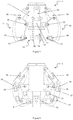
- figure 1 is an image of one embodiment of the pile cropper device (1).
- the figure shows the device from the side and shows the body of the cropper (11) rotationally connected to jaws (12) at a pivot point (15).
- the jaws comprise of a jaw assembly (12) and cutting teeth (13).
- the jaws are driven by hydraulic arms (14) and the internal parallel mechanism holds the tip of the teeth parallel to the desired plane of fracture of the concrete pile (not shown) and the rotation point (16) allows the tip to rotate.
- the jaw assembly comprises outer plates (18) and support elements (17).
- Figure 2 is a cross-sectional view of the device in figure 1 and shows the internal mechanism of the parallel linkage.
- FIG. 3 shows a detail view of the jaw assembly (12) and demonstrates one form of preferred parallel linkage.
- the top link (31) between the pivot point of the jaw (15) and the rotational connection (34) is, in this case, parallel to the plane of the desired fracture of the concrete pile.
- the tooth (13) is held by the tooth linkage (32) which is held parallel to the top link (31) by the jaw assembly (12) and the rotating link (33).
- the rotating link (33) between the rotational connection (34) at the top of the linkage and the rotational connection (35) at the bottom of the linkage is rotationally connected to both the top linkage (31) and the tooth linkage (32). This causes the tooth to remain parallel when the jaw actuates.
- Figure 4 shows another embodiment of the invention, the figure shows the body of the cropper (41) rotationally connected to jaws (42) at a pivot point (45).
- the jaws comprise of a jaw assembly (42) and cutting teeth (43).
- the jaws are driven by hydraulic arms (44) and the internal parallel mechanism holds the tip of the teeth parallel to the desired plane of fracture of the concrete pile (not shown),
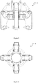
- Figure 5 shows the cropping device of figure 4 from a side view. The cropper is in its open position.
- Figure 6 shows the cropping device of figure 4 from the top. The cropper is in its open position.
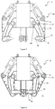
- Figure 7 shows a cross-section of the cropping device of figure 5 and demonstrates the internal parallel mechanism for this embodiment.
- the jaw assembly (42) contains a similar arrangement of linkages as figure 2 , however, the top linkage (71) connects the pivot point (74) directly to the body of the device.
- the top linkage (71) positions centre of the pivot point (74) onto the same plane as the centre of the jaw pivot point (45).
- Figure 8 shows the same cross-section of the apparatus as figure 7 but it is in a closed position and demonstrates the way with which the parallel mechanism causes the tooth to remain parallel.
- the principal advantage of devices according to this invention result from maintaining the orientation of the tooth relative to the pile to be, or being, cropped generally constant throughout its engagement with the pile, its cladding or its projecting reinforcement as the pile reduces in thickness by removal of a portion of mainly the concrete surround.
- This advantage follows through in the ability to deal similarly with piles of different thickness.
Landscapes
- Engineering & Computer Science (AREA)
- Mining & Mineral Resources (AREA)
- Life Sciences & Earth Sciences (AREA)
- General Life Sciences & Earth Sciences (AREA)
- Paleontology (AREA)
- Civil Engineering (AREA)
- General Engineering & Computer Science (AREA)
- Structural Engineering (AREA)
- Mechanical Engineering (AREA)
- Placing Or Removing Of Piles Or Sheet Piles, Or Accessories Thereof (AREA)
Claims (15)
- Pfahlschneidevorrichtung (1), beinhaltend ein Gehäuse (11, 41) welches um und/oder im Bereich eines zu schneidenden Pfahls angeordnet werden kann, wobei das Gehäuse eine oder mehrere Pfahlschneideklaue(n) (12, 42) besitzt, welche schwenkbar am Gehäuse befestigt ist/sind, wobei die Klauen einen oder mehrere Pfahlschneidezahn/Pfahlschneidezähne (13, 43) besitzen, welche schwenkbar an der/den Klaue(n) befestigt sind und schwenkbar am Gehäuse in der Weise befestigt sind, dass im Gebrauch der eine Zahn oder die mehreren Zähne (13, 43) mit einer Umhüllung und/oder Verstärkung des Pfahls in Eingriff gehen oder sich davon lösen, wobei am Eingriffspunkt zwischen dem Schneidezahn bzw. den Schneidezähnen (13,43) und dem zu schneidenden Pfahl die planare Ausrichtung des Zahns oder der Zähne in Bezug auf die Achse des Pfahls allgemein durch die Position der Klaue (12, 42) in Verbindung zum Gehäuse (11,41) und folglich durch die Schwankung in der Dicke der Verstärkung und/oder Umhüllung, welche vom Pfahl geschnitten werden soll, unberührt bleibt.
- Vorrichtung (1) nach Anspruch 1, bei welcher das Mittel, mit welchem die Pfahlschneidezähne (13, 43) mit dem Gehäuse (11, 41) verbunden sind, ein oder mehrere Schwenkzapfen (15, 34; 16,35) ist/sind.
- Vorrichtung (1) nach einem der vorhergehenden Ansprüche, bei welcher der oder jeder Schneidzahn (13, 42) mit zwei voneinander entfernten Schwenkpunkten (16, 35) zur schwenkbaren Montage an dem Gehäuse versehen ist.
- Vorrichtung (1) nach Anspruch 3, bei welcher einer der voneinander entfernten Schwenkpunkte (16) mit einem Gestänge (33, 73) verbunden ist, welches mit dem Gehäuse verbunden ist.
- Vorrichtung (1) nach Anspruch 4, bei welcher das Gestänge (33, 73) ein Drehgestänge ist.
- Vorrichtung (1) nach einem der vorhergehenden Ansprüche, bei welcher die Klaue (12, 42) ein paralleles Gestänge (31, 32; 71, 72) beinhaltet, um den oder die Zähne (13, 43) in einer planaren Ausrichtung zu halten.
- Vorrichtung (1) nach Anspruch 1, bei welcher die planare Ausrichtung des Zahns oder der Zähne (13,43) im Gebrauch im Allgemeinen konstant über eine Spanne seiner/ihrer Bewegung bleibt, vom Eingriff mit der Umhüllung und/oder Verstärkung bis zum Lösen hiervon.
- Vorrichtung (1) nach einem der vorhergehenden Ansprüche, bei welcher die planare Ausrichtung im Allgemeinen konstant bleibt und von der Dicke des zu schneidenden Pfahls unabhängig ist.
- Vorrichtung (1) nach einem der vorhergehenden Ansprüche, bei welcher die Klaue (12, 42) für angetriebene Bewegung durch einen Hydraulikzylinder (14, 44) bereitgestellt und montiert ist, und wobei die Klaue (12, 42) mehr als drei Schwenkpunkte (15, 16, 34, 35) für bewegliche Komponenten der Vorrichtung beinhaltet.
- Vorrichtung (1) nach Anspruch 9, bei welcher fünf solche Schwenkpunkte (15, 16, 34, 35; 45, 74, 75) bereitgestellt sind.
- Vorrichtung (1) nach einem der vorhergehenden Ansprüche, bei welcher das Gehäuse (11, 41) mit einem Erweiterungsarm (71) assoziiert ist, welcher einen Schwenkpunkt (74) an oder in dem Bereich seines von diesem Gehäuse (11,41) entfernten Endes für eine bewegliche Komponente (42) der Vorrichtung enthält.
- Vorrichtung (1) nach einem der vorhergehenden Ansprüche, bei welcher der oder jeder Schneidezahn (13, 43) mit zwei voneinander entfernten Schwenkpunkten (16, 35; 75) zur schwenkbaren Montage an dem Gehäuse versehen ist.
- Vorrichtung (1) nach einem der vorhergehenden Ansprüche, beinhaltend mindestens eine hydraulisch betätigte Klaue (12, 42), welche drehbar mit einem Schwenkpunkt (15, 45) am Gehäuse verbunden ist, wobei die Vorrichtung mit solchen Klauen versehen ist, welche geeignet sind, mit einem parallelen Gestänge (13, 32) zwischen einem Drehmittelpunkt der Klaue und einem Schneidezahn (13) betrieben zu werden.
- Vorrichtung (1) nach einem der vorhergehenden Ansprüche, bei welcher ein Schwenkpunkt (15) am Gehäuse (11, 41), welcher drehbar mit einer Klaue (12) verbunden ist, starr mit einem zweiten Punkt (34) verbunden ist, welcher unabhängig von der Klaue ist, wobei eine gedachte Linie, welche die beiden Punkte (15, 34) verbindet, parallel zu einer gewünschten Schneidebene ist, wobei die beiden Punkte drehbar mit einem Schneidezahn (13) durch ein mittleres Gestänge (32, 33) und die Klaue verbunden sind, wobei die Klaue drehbar mit dem Schwenkpunkt und der Vorderseite des Schneidezahns (13) verbunden ist, und das mittlere Gestänge (32, 33) drehbar von dem zweiten Punkt (34) mit einem sekundären Schwenkpunkt (35) des Schneidezahns (13) verbunden ist.
- Vorrichtung (1) nach Anspruch 14, bei welcher der Abstand zwischen dem zweiten Punkt (34) und dem sekundären Schwenkpunkt (35) des Schneidezahns (13) derselbe ist wie der Abstand zwischen dem Drehmittelpunkt und dem Punkt, mit welchem dieser an einem primären Schwenkpunkt (16) des Schneidezahns verbunden ist, wobei der Abstand zwischen dem Drehmittelpunkt und dem zweiten Punkt (34) derselbe ist wie der Abstand zwischen dem primären (16) und dem sekundären Schwenkpunkt (35) des Schneidezahns (13).
Applications Claiming Priority (2)
| Application Number | Priority Date | Filing Date | Title |
|---|---|---|---|
| GB1318599.6A GB2519380B (en) | 2013-10-21 | 2013-10-21 | Pile cropping device |
| PCT/GB2014/053108 WO2015059451A1 (en) | 2013-10-21 | 2014-10-16 | Pile cropping device |
Publications (3)
| Publication Number | Publication Date |
|---|---|
| EP3066264A1 EP3066264A1 (de) | 2016-09-14 |
| EP3066264B1 true EP3066264B1 (de) | 2018-10-03 |
| EP3066264B8 EP3066264B8 (de) | 2019-05-29 |
Family
ID=49727113
Family Applications (1)
| Application Number | Title | Priority Date | Filing Date |
|---|---|---|---|
| EP14790259.7A Active EP3066264B8 (de) | 2013-10-21 | 2014-10-16 | Pfahlschneider |
Country Status (3)
| Country | Link |
|---|---|
| EP (1) | EP3066264B8 (de) |
| GB (1) | GB2519380B (de) |
| WO (1) | WO2015059451A1 (de) |
Families Citing this family (3)
| Publication number | Priority date | Publication date | Assignee | Title |
|---|---|---|---|---|
| CN104912077A (zh) * | 2015-06-29 | 2015-09-16 | 上海胜真珊机械科技有限公司 | 全自动液压截桩机 |
| US11408140B2 (en) | 2016-03-18 | 2022-08-09 | Creative Crushers Ltd | Pile croppers and methods for cutting piles |
| RU198971U1 (ru) * | 2019-12-04 | 2020-08-05 | Федеральное государственное бюджетное образовательное учреждение высшего образования "Ярославский государственный технический университет" ФГБОУВО "ЯГТУ" | Устройство для срезания железобетонных свай |
Family Cites Families (10)
| Publication number | Priority date | Publication date | Assignee | Title |
|---|---|---|---|---|
| GB1394355A (en) * | 1972-08-25 | 1975-05-14 | Japan National Railway | Crusher head for breaking concrete structures |
| DE3618191A1 (de) * | 1986-05-30 | 1987-12-03 | Michael Barnsteiner | Betonbrechzange |
| DE58903074D1 (de) | 1988-04-27 | 1993-02-04 | Diaber Ag | Einrichtung zur freilegung der armierungseisen von betonpfaehlen. |
| JP2540210B2 (ja) * | 1989-06-19 | 1996-10-02 | 株式会社坂戸工作所 | 破砕機 |
| DE19812454C1 (de) * | 1998-03-23 | 1999-07-22 | Darda Systemtechnik Gmbh | Abbruchzange |
| GB9822265D0 (en) * | 1998-10-14 | 1998-12-09 | Roxbury Ltd | Improvements in or relating to pile cutters |
| IT1310857B1 (it) * | 1999-10-18 | 2002-02-22 | Mantovanibenne S R L | Dispositivo per la scapitozzatura di pali |
| CN201400892Y (zh) * | 2009-02-27 | 2010-02-10 | 荣成市龙河金属加工厂 | 液压桩头破碎装置 |
| CN101487259A (zh) * | 2009-02-27 | 2009-07-22 | 荣成市龙河金属加工厂 | 液压桩头破碎装置 |
| GB2470364A (en) * | 2009-05-19 | 2010-11-24 | Michael J Williams | Hydraulic tool to crush above ground extension of a concrete pile. |
-
2013
- 2013-10-21 GB GB1318599.6A patent/GB2519380B/en not_active Expired - Fee Related
-
2014
- 2014-10-16 EP EP14790259.7A patent/EP3066264B8/de active Active
- 2014-10-16 WO PCT/GB2014/053108 patent/WO2015059451A1/en not_active Ceased
Non-Patent Citations (1)
| Title |
|---|
| None * |
Also Published As
| Publication number | Publication date |
|---|---|
| EP3066264B8 (de) | 2019-05-29 |
| WO2015059451A1 (en) | 2015-04-30 |
| GB201318599D0 (en) | 2013-12-04 |
| GB2519380B (en) | 2015-12-23 |
| GB2519380A (en) | 2015-04-22 |
| EP3066264A1 (de) | 2016-09-14 |
Similar Documents
| Publication | Publication Date | Title |
|---|---|---|
| EP2171271B1 (de) | Windgenerator mit zusammenklappbarem mast | |
| EP3066264B1 (de) | Pfahlschneider | |
| CN106522071B (zh) | 电磁式钢板铺设车 | |
| US20180058029A1 (en) | Device for cutting concrete piles | |
| WO1993005923A1 (en) | Apparatus for cutting an article into sheets | |
| EP0367805A1 (de) | Blechschereneinheit für den auslegerarn einer baggers | |
| WO2010133862A2 (en) | Pile cropping apparatus | |
| JP2017031681A (ja) | 煙突解体用足場および煙突解体工法 | |
| CN104192577B (zh) | 一种斗轮堆取料机的斗轮挡料装置 | |
| US10450715B2 (en) | Powered lifting station for and method for lifting a slab foundation | |
| JP2022030188A (ja) | グラブバケット | |
| CN202877438U (zh) | 便携式钢筋弯曲机 | |
| KR102440806B1 (ko) | 승하강식 풍력 발전기 | |
| CN111619420B (zh) | 一种建筑施工用便捷泥沙车 | |
| JP6247457B2 (ja) | 建設機械 | |
| KR20220146259A (ko) | 굴삭기용 집게장치 | |
| CN210857330U (zh) | 一种cfg桩用环形挖土器 | |
| JP4671987B2 (ja) | 笠コンクリートブロックの施工用移動型枠 | |
| CN211775870U (zh) | 一种建筑工地用的混凝土抹平机 | |
| CN111021680B (zh) | 一种铲灰浆抹墙机及使用方法 | |
| JP2021119273A (ja) | 建て起こし装置、保護部材及び建て起こし装置の設置構造 | |
| JP7553253B2 (ja) | 排気筒解体方法 | |
| CN210066870U (zh) | 一种带剪切装置的破碎锤 | |
| CN213062356U (zh) | 市政工程用管道疏通器 | |
| WO2018158493A1 (en) | Device for cutting a metal profile |
Legal Events
| Date | Code | Title | Description |
|---|---|---|---|
| PUAI | Public reference made under article 153(3) epc to a published international application that has entered the european phase |
Free format text: ORIGINAL CODE: 0009012 |
|
| 17P | Request for examination filed |
Effective date: 20160510 |
|
| AK | Designated contracting states |
Kind code of ref document: A1 Designated state(s): AL AT BE BG CH CY CZ DE DK EE ES FI FR GB GR HR HU IE IS IT LI LT LU LV MC MK MT NL NO PL PT RO RS SE SI SK SM TR |
|
| AX | Request for extension of the european patent |
Extension state: BA ME |
|
| DAX | Request for extension of the european patent (deleted) | ||
| GRAP | Despatch of communication of intention to grant a patent |
Free format text: ORIGINAL CODE: EPIDOSNIGR1 |
|
| INTG | Intention to grant announced |
Effective date: 20180103 |
|
| GRAS | Grant fee paid |
Free format text: ORIGINAL CODE: EPIDOSNIGR3 |
|
| GRAA | (expected) grant |
Free format text: ORIGINAL CODE: 0009210 |
|
| AK | Designated contracting states |
Kind code of ref document: B1 Designated state(s): AL AT BE BG CH CY CZ DE DK EE ES FI FR GB GR HR HU IE IS IT LI LT LU LV MC MK MT NL NO PL PT RO RS SE SI SK SM TR |
|
| REG | Reference to a national code |
Ref country code: GB Ref legal event code: FG4D |
|
| REG | Reference to a national code |
Ref country code: CH Ref legal event code: EP Ref country code: AT Ref legal event code: REF Ref document number: 1048739 Country of ref document: AT Kind code of ref document: T Effective date: 20181015 |
|
| REG | Reference to a national code |
Ref country code: IE Ref legal event code: FG4D Ref country code: DE Ref legal event code: R096 Ref document number: 602014033441 Country of ref document: DE |
|
| REG | Reference to a national code |
Ref country code: DE Ref legal event code: R081 Ref document number: 602014033441 Country of ref document: DE Owner name: SUNBELT RENTALS LIMITED, GB Free format text: FORMER OWNER: ASTRA SITE SERVICES LTD., BATHGATE, LOTHIAN, GB Ref country code: NL Ref legal event code: FP |
|
| RAP2 | Party data changed (patent owner data changed or rights of a patent transferred) |
Owner name: ASHTEAD PLANT HIRE LIMITED |
|
| REG | Reference to a national code |
Ref country code: LT Ref legal event code: MG4D |
|
| REG | Reference to a national code |
Ref country code: DE Ref legal event code: R081 Ref document number: 602014033441 Country of ref document: DE Owner name: SUNBELT RENTALS LIMITED, GB Free format text: FORMER OWNER: ASHTEAD PLANT HIRE LIMITED, BIRCHWOOD, WARRINGTON, GB |
|
| REG | Reference to a national code |
Ref country code: AT Ref legal event code: MK05 Ref document number: 1048739 Country of ref document: AT Kind code of ref document: T Effective date: 20181003 |
|
| PG25 | Lapsed in a contracting state [announced via postgrant information from national office to epo] |
Ref country code: HR Free format text: LAPSE BECAUSE OF FAILURE TO SUBMIT A TRANSLATION OF THE DESCRIPTION OR TO PAY THE FEE WITHIN THE PRESCRIBED TIME-LIMIT Effective date: 20181003 Ref country code: PL Free format text: LAPSE BECAUSE OF FAILURE TO SUBMIT A TRANSLATION OF THE DESCRIPTION OR TO PAY THE FEE WITHIN THE PRESCRIBED TIME-LIMIT Effective date: 20181003 Ref country code: LT Free format text: LAPSE BECAUSE OF FAILURE TO SUBMIT A TRANSLATION OF THE DESCRIPTION OR TO PAY THE FEE WITHIN THE PRESCRIBED TIME-LIMIT Effective date: 20181003 Ref country code: NO Free format text: LAPSE BECAUSE OF FAILURE TO SUBMIT A TRANSLATION OF THE DESCRIPTION OR TO PAY THE FEE WITHIN THE PRESCRIBED TIME-LIMIT Effective date: 20190103 Ref country code: ES Free format text: LAPSE BECAUSE OF FAILURE TO SUBMIT A TRANSLATION OF THE DESCRIPTION OR TO PAY THE FEE WITHIN THE PRESCRIBED TIME-LIMIT Effective date: 20181003 Ref country code: LV Free format text: LAPSE BECAUSE OF FAILURE TO SUBMIT A TRANSLATION OF THE DESCRIPTION OR TO PAY THE FEE WITHIN THE PRESCRIBED TIME-LIMIT Effective date: 20181003 Ref country code: BG Free format text: LAPSE BECAUSE OF FAILURE TO SUBMIT A TRANSLATION OF THE DESCRIPTION OR TO PAY THE FEE WITHIN THE PRESCRIBED TIME-LIMIT Effective date: 20190103 Ref country code: CZ Free format text: LAPSE BECAUSE OF FAILURE TO SUBMIT A TRANSLATION OF THE DESCRIPTION OR TO PAY THE FEE WITHIN THE PRESCRIBED TIME-LIMIT Effective date: 20181003 Ref country code: FI Free format text: LAPSE BECAUSE OF FAILURE TO SUBMIT A TRANSLATION OF THE DESCRIPTION OR TO PAY THE FEE WITHIN THE PRESCRIBED TIME-LIMIT Effective date: 20181003 Ref country code: IS Free format text: LAPSE BECAUSE OF FAILURE TO SUBMIT A TRANSLATION OF THE DESCRIPTION OR TO PAY THE FEE WITHIN THE PRESCRIBED TIME-LIMIT Effective date: 20190203 Ref country code: AT Free format text: LAPSE BECAUSE OF FAILURE TO SUBMIT A TRANSLATION OF THE DESCRIPTION OR TO PAY THE FEE WITHIN THE PRESCRIBED TIME-LIMIT Effective date: 20181003 |
|
| REG | Reference to a national code |
Ref country code: CH Ref legal event code: PK Free format text: BERICHTIGUNG B8 |
|
| PG25 | Lapsed in a contracting state [announced via postgrant information from national office to epo] |
Ref country code: RS Free format text: LAPSE BECAUSE OF FAILURE TO SUBMIT A TRANSLATION OF THE DESCRIPTION OR TO PAY THE FEE WITHIN THE PRESCRIBED TIME-LIMIT Effective date: 20181003 Ref country code: GR Free format text: LAPSE BECAUSE OF FAILURE TO SUBMIT A TRANSLATION OF THE DESCRIPTION OR TO PAY THE FEE WITHIN THE PRESCRIBED TIME-LIMIT Effective date: 20190104 Ref country code: PT Free format text: LAPSE BECAUSE OF FAILURE TO SUBMIT A TRANSLATION OF THE DESCRIPTION OR TO PAY THE FEE WITHIN THE PRESCRIBED TIME-LIMIT Effective date: 20190203 Ref country code: SE Free format text: LAPSE BECAUSE OF FAILURE TO SUBMIT A TRANSLATION OF THE DESCRIPTION OR TO PAY THE FEE WITHIN THE PRESCRIBED TIME-LIMIT Effective date: 20181003 Ref country code: AL Free format text: LAPSE BECAUSE OF FAILURE TO SUBMIT A TRANSLATION OF THE DESCRIPTION OR TO PAY THE FEE WITHIN THE PRESCRIBED TIME-LIMIT Effective date: 20181003 |
|
| REG | Reference to a national code |
Ref country code: CH Ref legal event code: PL |
|
| REG | Reference to a national code |
Ref country code: BE Ref legal event code: MM Effective date: 20181031 |
|
| PG25 | Lapsed in a contracting state [announced via postgrant information from national office to epo] |
Ref country code: LU Free format text: LAPSE BECAUSE OF NON-PAYMENT OF DUE FEES Effective date: 20181016 |
|
| REG | Reference to a national code |
Ref country code: DE Ref legal event code: R097 Ref document number: 602014033441 Country of ref document: DE |
|
| PG25 | Lapsed in a contracting state [announced via postgrant information from national office to epo] |
Ref country code: DK Free format text: LAPSE BECAUSE OF FAILURE TO SUBMIT A TRANSLATION OF THE DESCRIPTION OR TO PAY THE FEE WITHIN THE PRESCRIBED TIME-LIMIT Effective date: 20181003 Ref country code: IT Free format text: LAPSE BECAUSE OF FAILURE TO SUBMIT A TRANSLATION OF THE DESCRIPTION OR TO PAY THE FEE WITHIN THE PRESCRIBED TIME-LIMIT Effective date: 20181003 |
|
| PLBE | No opposition filed within time limit |
Free format text: ORIGINAL CODE: 0009261 |
|
| STAA | Information on the status of an ep patent application or granted ep patent |
Free format text: STATUS: NO OPPOSITION FILED WITHIN TIME LIMIT |
|
| PG25 | Lapsed in a contracting state [announced via postgrant information from national office to epo] |
Ref country code: CH Free format text: LAPSE BECAUSE OF NON-PAYMENT OF DUE FEES Effective date: 20181031 Ref country code: LI Free format text: LAPSE BECAUSE OF NON-PAYMENT OF DUE FEES Effective date: 20181031 Ref country code: SK Free format text: LAPSE BECAUSE OF FAILURE TO SUBMIT A TRANSLATION OF THE DESCRIPTION OR TO PAY THE FEE WITHIN THE PRESCRIBED TIME-LIMIT Effective date: 20181003 Ref country code: MC Free format text: LAPSE BECAUSE OF FAILURE TO SUBMIT A TRANSLATION OF THE DESCRIPTION OR TO PAY THE FEE WITHIN THE PRESCRIBED TIME-LIMIT Effective date: 20181003 Ref country code: SM Free format text: LAPSE BECAUSE OF FAILURE TO SUBMIT A TRANSLATION OF THE DESCRIPTION OR TO PAY THE FEE WITHIN THE PRESCRIBED TIME-LIMIT Effective date: 20181003 Ref country code: RO Free format text: LAPSE BECAUSE OF FAILURE TO SUBMIT A TRANSLATION OF THE DESCRIPTION OR TO PAY THE FEE WITHIN THE PRESCRIBED TIME-LIMIT Effective date: 20181003 Ref country code: BE Free format text: LAPSE BECAUSE OF NON-PAYMENT OF DUE FEES Effective date: 20181031 Ref country code: EE Free format text: LAPSE BECAUSE OF FAILURE TO SUBMIT A TRANSLATION OF THE DESCRIPTION OR TO PAY THE FEE WITHIN THE PRESCRIBED TIME-LIMIT Effective date: 20181003 |
|
| 26N | No opposition filed |
Effective date: 20190704 |
|
| PG25 | Lapsed in a contracting state [announced via postgrant information from national office to epo] |
Ref country code: SI Free format text: LAPSE BECAUSE OF FAILURE TO SUBMIT A TRANSLATION OF THE DESCRIPTION OR TO PAY THE FEE WITHIN THE PRESCRIBED TIME-LIMIT Effective date: 20181003 |
|
| PG25 | Lapsed in a contracting state [announced via postgrant information from national office to epo] |
Ref country code: MT Free format text: LAPSE BECAUSE OF NON-PAYMENT OF DUE FEES Effective date: 20181016 |
|
| PG25 | Lapsed in a contracting state [announced via postgrant information from national office to epo] |
Ref country code: TR Free format text: LAPSE BECAUSE OF FAILURE TO SUBMIT A TRANSLATION OF THE DESCRIPTION OR TO PAY THE FEE WITHIN THE PRESCRIBED TIME-LIMIT Effective date: 20181003 |
|
| PG25 | Lapsed in a contracting state [announced via postgrant information from national office to epo] |
Ref country code: CY Free format text: LAPSE BECAUSE OF FAILURE TO SUBMIT A TRANSLATION OF THE DESCRIPTION OR TO PAY THE FEE WITHIN THE PRESCRIBED TIME-LIMIT Effective date: 20181003 Ref country code: HU Free format text: LAPSE BECAUSE OF FAILURE TO SUBMIT A TRANSLATION OF THE DESCRIPTION OR TO PAY THE FEE WITHIN THE PRESCRIBED TIME-LIMIT; INVALID AB INITIO Effective date: 20141016 Ref country code: MK Free format text: LAPSE BECAUSE OF NON-PAYMENT OF DUE FEES Effective date: 20181003 |
|
| REG | Reference to a national code |
Ref country code: DE Ref legal event code: R081 Ref document number: 602014033441 Country of ref document: DE Owner name: SUNBELT RENTALS LIMITED, GB Free format text: FORMER OWNER: ASHTEAD PLANT HIRE COMPANY LIMITED, LONDON, GB Ref country code: DE Ref legal event code: R081 Ref document number: 602014033441 Country of ref document: DE Owner name: SUNBELT RENTALS LIMITED, GB Free format text: FORMER OWNER: ASHTEAD PLANT HIRE COMPANY LIMITED, BIRCHWOOD, WARRINGTON, GB |
|
| REG | Reference to a national code |
Ref country code: NL Ref legal event code: HC Owner name: SUNBELT RENTALS LIMITED; GB Free format text: DETAILS ASSIGNMENT: CHANGE OF OWNER(S), CHANGE OF OWNER(S) NAME; FORMER OWNER NAME: ASHTEAD PLANT HIRE COMPANY LIMITED Effective date: 20230328 |
|
| PGFP | Annual fee paid to national office [announced via postgrant information from national office to epo] |
Ref country code: NL Payment date: 20250912 Year of fee payment: 12 |
|
| PGFP | Annual fee paid to national office [announced via postgrant information from national office to epo] |
Ref country code: GB Payment date: 20250828 Year of fee payment: 12 |
|
| PGFP | Annual fee paid to national office [announced via postgrant information from national office to epo] |
Ref country code: FR Payment date: 20250908 Year of fee payment: 12 |
|
| PGFP | Annual fee paid to national office [announced via postgrant information from national office to epo] |
Ref country code: IE Payment date: 20250909 Year of fee payment: 12 |
|
| PGFP | Annual fee paid to national office [announced via postgrant information from national office to epo] |
Ref country code: DE Payment date: 20250902 Year of fee payment: 12 |