EP3064374A1 - Tire - Google Patents
Tire Download PDFInfo
- Publication number
- EP3064374A1 EP3064374A1 EP14857781.0A EP14857781A EP3064374A1 EP 3064374 A1 EP3064374 A1 EP 3064374A1 EP 14857781 A EP14857781 A EP 14857781A EP 3064374 A1 EP3064374 A1 EP 3064374A1
- Authority
- EP
- European Patent Office
- Prior art keywords
- tire
- circumferential
- belt
- circumferential direction
- tread
- Prior art date
- Legal status (The legal status is an assumption and is not a legal conclusion. Google has not performed a legal analysis and makes no representation as to the accuracy of the status listed.)
- Granted
Links
Images


Classifications
-
- B—PERFORMING OPERATIONS; TRANSPORTING
- B60—VEHICLES IN GENERAL
- B60C—VEHICLE TYRES; TYRE INFLATION; TYRE CHANGING; CONNECTING VALVES TO INFLATABLE ELASTIC BODIES IN GENERAL; DEVICES OR ARRANGEMENTS RELATED TO TYRES
- B60C9/00—Reinforcements or ply arrangement of pneumatic tyres
- B60C9/18—Structure or arrangement of belts or breakers, crown-reinforcing or cushioning layers
- B60C9/20—Structure or arrangement of belts or breakers, crown-reinforcing or cushioning layers built-up from rubberised plies each having all cords arranged substantially parallel
- B60C9/22—Structure or arrangement of belts or breakers, crown-reinforcing or cushioning layers built-up from rubberised plies each having all cords arranged substantially parallel the plies being arranged with all cords disposed along the circumference of the tyre
-
- B—PERFORMING OPERATIONS; TRANSPORTING
- B60—VEHICLES IN GENERAL
- B60C—VEHICLE TYRES; TYRE INFLATION; TYRE CHANGING; CONNECTING VALVES TO INFLATABLE ELASTIC BODIES IN GENERAL; DEVICES OR ARRANGEMENTS RELATED TO TYRES
- B60C11/00—Tyre tread bands; Tread patterns; Anti-skid inserts
- B60C11/03—Tread patterns
- B60C11/0306—Patterns comprising block rows or discontinuous ribs
-
- B—PERFORMING OPERATIONS; TRANSPORTING
- B60—VEHICLES IN GENERAL
- B60C—VEHICLE TYRES; TYRE INFLATION; TYRE CHANGING; CONNECTING VALVES TO INFLATABLE ELASTIC BODIES IN GENERAL; DEVICES OR ARRANGEMENTS RELATED TO TYRES
- B60C11/00—Tyre tread bands; Tread patterns; Anti-skid inserts
- B60C11/03—Tread patterns
- B60C11/04—Tread patterns in which the raised area of the pattern consists only of continuous circumferential ribs, e.g. zig-zag
-
- B—PERFORMING OPERATIONS; TRANSPORTING
- B60—VEHICLES IN GENERAL
- B60C—VEHICLE TYRES; TYRE INFLATION; TYRE CHANGING; CONNECTING VALVES TO INFLATABLE ELASTIC BODIES IN GENERAL; DEVICES OR ARRANGEMENTS RELATED TO TYRES
- B60C9/00—Reinforcements or ply arrangement of pneumatic tyres
- B60C9/02—Carcasses
-
- B—PERFORMING OPERATIONS; TRANSPORTING
- B60—VEHICLES IN GENERAL
- B60C—VEHICLE TYRES; TYRE INFLATION; TYRE CHANGING; CONNECTING VALVES TO INFLATABLE ELASTIC BODIES IN GENERAL; DEVICES OR ARRANGEMENTS RELATED TO TYRES
- B60C9/00—Reinforcements or ply arrangement of pneumatic tyres
- B60C9/18—Structure or arrangement of belts or breakers, crown-reinforcing or cushioning layers
- B60C9/20—Structure or arrangement of belts or breakers, crown-reinforcing or cushioning layers built-up from rubberised plies each having all cords arranged substantially parallel
- B60C9/2003—Structure or arrangement of belts or breakers, crown-reinforcing or cushioning layers built-up from rubberised plies each having all cords arranged substantially parallel characterised by the materials of the belt cords
- B60C9/2009—Structure or arrangement of belts or breakers, crown-reinforcing or cushioning layers built-up from rubberised plies each having all cords arranged substantially parallel characterised by the materials of the belt cords comprising plies of different materials
-
- B—PERFORMING OPERATIONS; TRANSPORTING
- B60—VEHICLES IN GENERAL
- B60C—VEHICLE TYRES; TYRE INFLATION; TYRE CHANGING; CONNECTING VALVES TO INFLATABLE ELASTIC BODIES IN GENERAL; DEVICES OR ARRANGEMENTS RELATED TO TYRES
- B60C9/00—Reinforcements or ply arrangement of pneumatic tyres
- B60C9/18—Structure or arrangement of belts or breakers, crown-reinforcing or cushioning layers
- B60C9/20—Structure or arrangement of belts or breakers, crown-reinforcing or cushioning layers built-up from rubberised plies each having all cords arranged substantially parallel
- B60C2009/2012—Structure or arrangement of belts or breakers, crown-reinforcing or cushioning layers built-up from rubberised plies each having all cords arranged substantially parallel with particular configuration of the belt cords in the respective belt layers
- B60C2009/2019—Structure or arrangement of belts or breakers, crown-reinforcing or cushioning layers built-up from rubberised plies each having all cords arranged substantially parallel with particular configuration of the belt cords in the respective belt layers comprising cords at an angle of 30 to 60 degrees to the circumferential direction
-
- B—PERFORMING OPERATIONS; TRANSPORTING
- B60—VEHICLES IN GENERAL
- B60C—VEHICLE TYRES; TYRE INFLATION; TYRE CHANGING; CONNECTING VALVES TO INFLATABLE ELASTIC BODIES IN GENERAL; DEVICES OR ARRANGEMENTS RELATED TO TYRES
- B60C9/00—Reinforcements or ply arrangement of pneumatic tyres
- B60C9/18—Structure or arrangement of belts or breakers, crown-reinforcing or cushioning layers
- B60C9/20—Structure or arrangement of belts or breakers, crown-reinforcing or cushioning layers built-up from rubberised plies each having all cords arranged substantially parallel
- B60C2009/2048—Structure or arrangement of belts or breakers, crown-reinforcing or cushioning layers built-up from rubberised plies each having all cords arranged substantially parallel characterised by special physical properties of the belt plies
-
- B—PERFORMING OPERATIONS; TRANSPORTING
- B60—VEHICLES IN GENERAL
- B60C—VEHICLE TYRES; TYRE INFLATION; TYRE CHANGING; CONNECTING VALVES TO INFLATABLE ELASTIC BODIES IN GENERAL; DEVICES OR ARRANGEMENTS RELATED TO TYRES
- B60C9/00—Reinforcements or ply arrangement of pneumatic tyres
- B60C9/18—Structure or arrangement of belts or breakers, crown-reinforcing or cushioning layers
- B60C9/20—Structure or arrangement of belts or breakers, crown-reinforcing or cushioning layers built-up from rubberised plies each having all cords arranged substantially parallel
- B60C9/22—Structure or arrangement of belts or breakers, crown-reinforcing or cushioning layers built-up from rubberised plies each having all cords arranged substantially parallel the plies being arranged with all cords disposed along the circumference of the tyre
- B60C2009/2223—Structure or arrangement of belts or breakers, crown-reinforcing or cushioning layers built-up from rubberised plies each having all cords arranged substantially parallel the plies being arranged with all cords disposed along the circumference of the tyre with an interrupted zero degree ply, e.g. using two or more portions for the same ply
-
- B—PERFORMING OPERATIONS; TRANSPORTING
- B60—VEHICLES IN GENERAL
- B60C—VEHICLE TYRES; TYRE INFLATION; TYRE CHANGING; CONNECTING VALVES TO INFLATABLE ELASTIC BODIES IN GENERAL; DEVICES OR ARRANGEMENTS RELATED TO TYRES
- B60C11/00—Tyre tread bands; Tread patterns; Anti-skid inserts
- B60C11/03—Tread patterns
- B60C2011/0337—Tread patterns characterised by particular design features of the pattern
- B60C2011/0339—Grooves
- B60C2011/0341—Circumferential grooves
-
- B—PERFORMING OPERATIONS; TRANSPORTING
- B60—VEHICLES IN GENERAL
- B60C—VEHICLE TYRES; TYRE INFLATION; TYRE CHANGING; CONNECTING VALVES TO INFLATABLE ELASTIC BODIES IN GENERAL; DEVICES OR ARRANGEMENTS RELATED TO TYRES
- B60C11/00—Tyre tread bands; Tread patterns; Anti-skid inserts
- B60C11/03—Tread patterns
- B60C2011/0337—Tread patterns characterised by particular design features of the pattern
- B60C2011/0386—Continuous ribs
-
- B—PERFORMING OPERATIONS; TRANSPORTING
- B60—VEHICLES IN GENERAL
- B60C—VEHICLE TYRES; TYRE INFLATION; TYRE CHANGING; CONNECTING VALVES TO INFLATABLE ELASTIC BODIES IN GENERAL; DEVICES OR ARRANGEMENTS RELATED TO TYRES
- B60C3/00—Tyres characterised by the transverse section
- B60C3/04—Tyres characterised by the transverse section characterised by the relative dimensions of the section, e.g. low profile
-
- Y—GENERAL TAGGING OF NEW TECHNOLOGICAL DEVELOPMENTS; GENERAL TAGGING OF CROSS-SECTIONAL TECHNOLOGIES SPANNING OVER SEVERAL SECTIONS OF THE IPC; TECHNICAL SUBJECTS COVERED BY FORMER USPC CROSS-REFERENCE ART COLLECTIONS [XRACs] AND DIGESTS
- Y02—TECHNOLOGIES OR APPLICATIONS FOR MITIGATION OR ADAPTATION AGAINST CLIMATE CHANGE
- Y02T—CLIMATE CHANGE MITIGATION TECHNOLOGIES RELATED TO TRANSPORTATION
- Y02T10/00—Road transport of goods or passengers
- Y02T10/80—Technologies aiming to reduce greenhouse gasses emissions common to all road transportation technologies
- Y02T10/86—Optimisation of rolling resistance, e.g. weight reduction
Definitions
- This disclosure relates to a pneumatic tire that has improved steering stability without causing noise performance to deteriorate.
- One known way of reinforcing a pneumatic tire is to dispose, at the outer side in the tire radial direction of the crown portion of the carcass extending between bead portions, an inclined belt layer including cords extending at an inclination relative to the tire circumferential direction and a circumferential belt layer including cords extending along the tire circumferential direction.
- the tire is reinforced for example by using the inclined belt layer to ensure rigidity in the tire width direction and to yield cornering power, which is one important index of steering stability, and by using the circumferential belt layer to ensure rigidity in the tire circumferential direction and suppress radial growth of the tire when driving at high speed.
- a pneumatic tire that has improved steering stability without causing noise performance to deteriorate can be provided.
- FIG. 1 is a schematic plan view of a tread 6 in a tire according to one of the embodiments, in this example a pneumatic radial tire for passenger vehicles.
- three land portions 5 are defined by a plurality (two in the illustrated example) of circumferential grooves 1 extending in the tire circumferential direction on either side of the tire equator CL and the ground contact edges TE of the tread 6.
- the circumferential grooves 1 are linear in the illustrated example but may be a non-linear shape, such as zigzag-shaped, serrated-shaped, wavy-shaped, or the like. While not illustrated, lateral grooves, sipes, or the like extending at an angle of 0° or more to less than 90° relative to the tire width direction may be provided on the tread 6 in addition to the circumferential grooves 1.
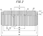
- FIG. 2 illustrates the belt structure of the tire illustrated in FIG. 1 .
- the disclosed tire includes a carcass 12 toroidally extending between a pair of bead portions, an inclined belt 3 formed by at least one inclined belt layer (in FIG. 4 , a wide inclined belt layer 3a with a width of W 1 and a narrow inclined belt layer 3b with a width of W 2 in the tire width direction) including cords that extend at an inclination relative to the tire circumferential direction and a circumferential belt 4 formed by at least one circumferential belt layer (in the example in FIG.
- the belt layers are layered in the order of the inclined belt layers 3a, 3b and the circumferential belt layers 4a, 4b from the inner side in the tire radial direction towards the outer side.
- the inclination angles ⁇ 1 and ⁇ 2 of the inclined belt layers 3a and 3b relative to the tire circumferential direction be 35° or more to 90° or less.
- the rigidity of the inclined belt layer in the tire width direction can be increased, and the cornering power, which is one important index of steering stability, can be increased. If the inclination angles ⁇ 1 and ⁇ 2 of the inclined belt layers 3a and 3b are less than 35°, then the rigidity relative to the tire width direction decreases. As a result, sufficient steering stability cannot be obtained, especially when cornering, and furthermore the shear deformation of rubber between layers increases, which tends to make the rolling resistance degrade.
- the inclination angles ⁇ 1 and ⁇ 2 are more preferably 55° or more to 85° or less. In this case, the cornering power can more reliably be increased.
- the circumferential belts 4a and 4b disposed on the outer side of the inclined belt layers 3a and 3b in the tire radial direction are split up in the tire width direction.
- the circumferential belt layers 4a and 4b overlap by a width W 3 in the tire width direction in a certain region (central region C) that includes the tire equator CL.
- the tread 6 include a land portion R (rib-like land portion) continuous in the tire circumferential direction in a region of the surface of the tread 6 including at least the tire equator CL.
- the land portion R continuous in the tire circumferential direction is defined by a pair of circumferential grooves 1 disposed on either side of the tire equator CL.
- the ground contact length is preferably greater than the outer sides of the tread in the tire width direction.
- the ground contact length of the tread becomes shorter near the tire equator CL than at the outer sides in the tire width direction.
- the width Wr of the land portion R in the tire width direction is too small, the amount of increase in the cornering power also reduces.
- the width Wr is therefore preferably 20 mm or greater.
- the upper limit on the width Wr is preferably 40 mm.
- the number of circumferential belt layers 4 in the tire radial direction is preferably greater in the central region C than in other regions, as in the embodiment illustrated in FIG. 2 . According to such a structure, the circumferential rigidity of the central region C can be reliably increased.
- the tire circumferential direction rigidity of the circumferential belt 4 illustrated in FIG. 2 does not change continuously from the central region C towards the other regions at the outer side in the tire width direction but rather changes at the boundary between regions.
- a configuration may be adopted wherein the tire circumferential direction rigidity per unit width in the other regions increases towards the central region C, for example by the rigidity decreasing gradually or in a stepwise manner from the inside towards the outside in the tire width direction.
- the tread 6 preferably includes a plurality of circumferential grooves 1 extending along the tire circumferential direction, and edges CE of the central region C in the tire width direction are preferably positioned within an opening width of the circumferential grooves 1.
- the edges CE of the central region C in the tire width direction are disposed in the tread 6 at the positions of the circumferential grooves 1 that have relatively low rigidity.
- the gauge distribution and rigidity of the central region C can be made uniform at the positions of the circumferential grooves 1. Therefore, the ground contact length near the tire equator CL can be more sufficiently ensured, and the cornering power can be further increased.
- the disclosed tire preferably includes one or two of the inclined belt layers 3 and includes two of the circumferential belt layers 4 in the central region C and one circumferential belt layer 4 in the other regions. According to this structure, sufficient durability can be obtained while avoiding an excessive increase in production costs and tire weight.
- the width W 3 of the central region C in the tire width direction, centered on the tire equator CL, is preferably between 0.2 and 0.6 times the width W 4 of the circumferential belt 4 in the tire width direction.
- the relationship 0.2 ⁇ W 4 ⁇ W 3 ⁇ 0.6 ⁇ W 4 is preferably satisfied.
- the disclosed tire is particularly preferably used as a pneumatic radial tire for passenger vehicles in which, when the internal pressure of the disclosed tire is set to 250 kPa or higher, an SW/OD ratio of the sectional width SW to the outer diameter OD of the tire is 0.26 or less if the tire has a sectional width SW of less than 165 (mm), whereas the sectional width SW and the outer diameter OD of the tire satisfy the relational expression OD ⁇ 2.135 ⁇ SW + 282.3 if the tire has a sectional width SW of 165 (mm) or greater.
- sectional width SW of the tire is defined as the direct distance between sidewalls that include patterns, characters, or the like on the side surface of the tire, i.e. the width obtained by subtracting the thickness of patterns or characters on the side surface of the tire from the total width, when the tire is mounted on an applicable rim, filled to a predetermined air pressure, and placed under no load.
- outer diameter OD of the tire refers to the outer diameter in the tire radial direction when the tire is mounted on an applicable rim, filled to a predetermined air pressure, and placed under no load.
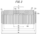
- the belt structure illustrated in FIG. 2 has been used as an example of the belt structure in this disclosure, but the belt structure in FIG. 3 , for example, may be adopted.
- a narrow circumferential belt layer 34a may be disposed at the outer side of the inclined belt layers 33a and 33b in the tire radial direction, and a wide circumferential belt layer 34b may be disposed so as to cover the circumferential belt layer 34a.
- the number of circumferential belt layers in the tire radial direction is preferably larger than in other regions, as described above.
- Another approach that can be taken in some cases, however, is to adjust the number of cords implanted in the circumferential belt layer or the strength per cord.
- Example Tires and Comparative Tires (all having a tire size of 165/60R19) according to the specifications listed in Table 1 were prepared, and the cornering power, rolling resistance performance, and noise performance were evaluated.
- Each sample tire had a carcass toroidally extending between a pair of bead portions, two inclined belt layers and one or more circumferential belt layers on the outer side of the crown portion of the carcass in the tire radial direction, and a tread.
- Steel cords were used as the cords forming the inclined belt layer, and aramid was used in the cords forming the circumferential belt layer(s).
- each sample tire was mounted on a vehicle and measured in a flat-belt cornering tester.
- the cornering power obtained under the conditions of a belt speed of 100 km/h and a load condition corresponding to the maximum load capability for the applicable size / ply rating was measured.
- each sample tire was mounted on a vehicle and placed on a running test drum, which was rotated at a speed of 100 km/h to measure the rolling resistance.
- the results are listed in Table 1. The results were evaluated as an index, with the rolling resistance of Comparative Example Tire 1 being 100. A lower value for the index indicates better rolling resistance performance.
- each sample tire was mounted on a vehicle and placed on a running test drum, which was rotated at a speed of 100 km/h to measure the noise level with a traveling microphone method.
- the results are listed in Table 1. The results were evaluated as the difference from the noise level of Comparative Example Tire 1. A lower value indicates a better effect of reducing noise.
- Example Tires 1 to 11 exhibited improved cornering power along with better rolling resistance performance and noise performance
Abstract
Description
- This disclosure relates to a pneumatic tire that has improved steering stability without causing noise performance to deteriorate.
- One known way of reinforcing a pneumatic tire is to dispose, at the outer side in the tire radial direction of the crown portion of the carcass extending between bead portions, an inclined belt layer including cords extending at an inclination relative to the tire circumferential direction and a circumferential belt layer including cords extending along the tire circumferential direction.
- In other words, the tire is reinforced for example by using the inclined belt layer to ensure rigidity in the tire width direction and to yield cornering power, which is one important index of steering stability, and by using the circumferential belt layer to ensure rigidity in the tire circumferential direction and suppress radial growth of the tire when driving at high speed.
- In general, since a tire with larger cornering power has excellent steering stability, it is desirable to increase cornering power. Increasing the rigidity of the inclined belt layer in the tire width direction is an effective way of increasing cornering power. Specifically, steeply inclining the cords in the inclined belt layer relative to the tire circumferential direction is one possible approach.
- It has been discovered, however, that increasing the cord inclination angle of the inclined belt layer changes the vibration mode of the tire and causes large noise emission from the tread surface, thereby causing the noise performance to deteriorate.
- It would therefore be helpful to provide a pneumatic tire that has improved steering stability without causing noise performance to deteriorate.
- Upon diligently studying how to solve the above-mentioned problem, we discovered that in a tire in which the cord inclination angle of the inclined belt layer is increased, the occurrence of noise emission can be suppressed by increasing the rigidity of the circumferential belt layer across a predetermined region that includes the tire equator. In this case, however, we discovered that the cornering power sometimes actually decreases. By studying the cause, we discovered that the cornering power decreases as a result of the ground contact length of the tread surface corresponding to the region in which the circumferential belt layer has high rigidity being shorter than in other portions.
- We carefully studied how to make steering stability, represented by cornering power, compatible with noise performance, thereby completing this disclosure.
- We provide the following:
- (1) A pneumatic tire according to this disclosure comprises a carcass toroidally extending between a pair of bead portions; an inclined belt formed by one or more inclined belt layers including cords that extend at an inclination relative to a tire circumferential direction and a circumferential belt formed by one or more circumferential belt layers including cords that extend along the tire circumferential direction, the inclined belt and the circumferential belt being provided at an outer side of a crown portion of the carcass in a tire radial direction; and a tread disposed at an outer side of the circumferential belt in the tire radial direction; wherein an inclination angle of the cords in the one or more inclined belt layers relative to the tire circumferential direction is 35° or more to 90° or less; the circumferential belt has a higher tire circumferential direction rigidity per unit width in a central region including a tire equator than in other regions; and in a region of a surface of the tread including at least the tire equator, the tread includes a land portion continuous in the tire circumferential direction.
Our pneumatic tire with this structure can improve steering stability without causing noise performance to deteriorate.
As used herein, the phrase "cords extending along the tire circumferential direction" includes not only the case of the cords being parallel to the tire circumferential direction, but also the case of the cords being slightly inclined relative to the tire circumferential direction (at an inclination angle of 5° or less) for example due to forming the belt layer by spirally winding strips of rubber-coated cords.
The phrase "land portion continuous in the tire circumferential direction" refers to a land portion that extends in the tire circumferential direction without being crossed by a groove. In other words, when the land portion is cut along the tire circumferential direction, no groove (excluding sipes or the like) is present at any position along the surface of the cut. For example, in the case of a rib-shaped land portion defined by two zigzag-shaped circumferential grooves, the land portion continuous in the tire circumferential direction refers to the portion within the rib-like land portion that, in planar view of the tread, has the shortest width between the innermost point of one circumferential groove and the innermost point of the other circumferential groove in the tire width direction.
The tire of this disclosure is used by being attached to an applicable rim. The "applicable rim" is an industrial standard effective in the region where the tire is manufactured and used and refers to a standard rim at an applicable size as described in the JATMA YEAR BOOK in Japan, the ETRTO STANDARDS MANUAL in Europe, the TRA YEAR BOOK in the United States of America, or the like (specifically the Measuring Rim in the ETRTO STANDARDS MANUAL and the Design Rim in the TRA YEAR BOOK).
In this disclosure, measurements such as the width in the tire width direction of the inclined belt layer and the circumferential belt layer are taken when the tire is mounted on the applicable rim, air pressure corresponding to the maximum load capability in the applicable size / ply rating described in JATMA or the like ("predetermined air pressure") is applied, and no load is applied. - (2) In the pneumatic tire according to this disclosure, a width, in a tire width direction, of the land portion continuous in the tire circumferential direction is preferably 20 mm or more to 40 mm or less. According to this structure, the cornering power can reliably be increased while maintaining the drainage performance of the tire.
- (3) In the pneumatic tire according to this disclosure, the number of the circumferential belt layers in the tire radial direction is preferably greater in the central region than in the other regions. According to this structure, the rolling resistance performance and the noise performance can more reliably be improved.
- (4) In the pneumatic tire according to this disclosure, the tread preferably comprises a plurality of circumferential grooves extending along the tire circumferential direction, and edges of the central region in the tire width direction are preferably positioned within an opening width of the circumferential grooves. According to this structure, the cornering power can more reliably be increased.
- (5) The pneumatic tire according to this disclosure preferably comprises one or two of the inclined belt layers and comprises two of the circumferential belt layers in the central region and one of the circumferential belt layers in the other regions. According to this structure, an excessive increase in production costs and tire weight can be avoided.
- According to this disclosure, a pneumatic tire that has improved steering stability without causing noise performance to deteriorate can be provided.
- In the accompanying drawings:
-
FIG. 1 is a schematic plan view of the tread in the tire according to one of the embodiments; -
FIG. 2 is a plan view of the belt structure in the tire illustrated inFIG. 1 ; -
FIG. 3 is a plan view of the belt structure in the tire according to another one of the embodiments; -
FIG. 4 illustrates the effects of a preferred structure in this disclosure; -
FIG. 5 is a schematic plan view of the tread in a tire of a Comparative Example; -
FIG. 6 is a plan view of the belt structure in the tire illustrated inFIG. 5 ; and -
FIGS. 7A, 7B, and 7C illustrate the placement position of circumferential grooves in the tread of the disclosed tire. - The following describes, in detail, exemplary embodiments of our pneumatic tire (also referred to below simply as a "tire") with reference to the drawings.
-
FIG. 1 is a schematic plan view of a tread 6 in a tire according to one of the embodiments, in this example a pneumatic radial tire for passenger vehicles. On the tread 6 of this tire, threeland portions 5 are defined by a plurality (two in the illustrated example) ofcircumferential grooves 1 extending in the tire circumferential direction on either side of the tire equator CL and the ground contact edges TE of the tread 6. Thecircumferential grooves 1 are linear in the illustrated example but may be a non-linear shape, such as zigzag-shaped, serrated-shaped, wavy-shaped, or the like. While not illustrated, lateral grooves, sipes, or the like extending at an angle of 0° or more to less than 90° relative to the tire width direction may be provided on the tread 6 in addition to thecircumferential grooves 1. -
FIG. 2 illustrates the belt structure of the tire illustrated inFIG. 1 . As illustrated inFIG. 4 , the disclosed tire includes acarcass 12 toroidally extending between a pair of bead portions, aninclined belt 3 formed by at least one inclined belt layer (inFIG. 4 , a wideinclined belt layer 3a with a width of W1 and a narrowinclined belt layer 3b with a width of W2 in the tire width direction) including cords that extend at an inclination relative to the tire circumferential direction and acircumferential belt 4 formed by at least one circumferential belt layer (in the example inFIG. 4 , twocircumferential belt layers inclined belt 3 and thecircumferential belt 4 being provided at the outer side of a crown portion of the carcass in the tire radial direction, and a tread 6 (seeFIG. 1 ) disposed at the outer side of thecircumferential belt 4 in the tire radial direction. In this embodiment, relative to the tire circumferential direction, the cords in theinclined belt layer 3a extend at an inclination angle of θ1, and the cords in theinclined belt layer 3b extend at an inclination angle of θ2 in the opposite direction from the cords in theinclined belt layer 3a, so as to sandwich the tire equator CL therebetween. In this embodiment, the belt layers are layered in the order of theinclined belt layers circumferential belt layers - In the disclosed tire, it is crucial that the inclination angles θ1 and θ2 of the
inclined belt layers - According to the disclosed tire with such a structure, the rigidity of the inclined belt layer in the tire width direction can be increased, and the cornering power, which is one important index of steering stability, can be increased. If the inclination angles θ1 and θ2 of the
inclined belt layers - The inclination angles θ1 and θ2 are more preferably 55° or more to 85° or less. In this case, the cornering power can more reliably be increased.
- In the Embodiment illustrated in
FIG. 2 , thecircumferential belts inclined belt layers circumferential belt layer 4b on the outer side of thecircumferential belt layer 4a in the tire radial direction, thecircumferential belt layers - In this way, in the disclosed tire, not only is it crucial to restrict the inclination angle of the cords in the
inclined belt layers circumferential belt 4 above the tire circumferential direction rigidity per unit width of other regions in thecircumferential belt 4. - Many tires in which the cords in the inclined belt layers 3a and 3b are inclined relative to the tire circumferential direction within the scope of this disclosure (35° or more to 90° or less) have a shape as indicated by the dash-double dot line in
FIG. 4 , such that the tread surface uniformly undergoes significant vibration in the high frequency range of 400 Hz to 2 kHz in the primary, secondary or ternary vibration modes in the cross-sectional direction, thereby causing a large noise emission. Therefore, locally increasing the tire circumferential rigidity of the central portion of the tread 6 in the tire width direction makes the central portion of the tread in the tire width direction less prone to expansion in the tire circumferential direction, thereby suppressing expansion of the tread surface in the tire circumferential direction (indicated with the dashed line inFIG. 4 ). As a result, noise emission can be reduced. - Furthermore, locally increasing the rigidity of the region including the tire equator CL makes the local shear strain of the top rubber (the rubber forming the tread surface layer) larger, thereby also increasing the attenuation of the vibration mode. Improvements to change the rigidity in the tire circumferential direction, as in this disclosure, correspond to an increase in the ring rigidity of the tire and to a change in the direction that suppresses the eccentricity of the tire. Hence, the rolling resistance performance does not deteriorate easily.
- Furthermore, in the disclosed tire, it is crucial that the tread 6 include a land portion R (rib-like land portion) continuous in the tire circumferential direction in a region of the surface of the tread 6 including at least the tire equator CL. For example, in the embodiment illustrated in
FIG. 1 , the land portion R continuous in the tire circumferential direction is defined by a pair ofcircumferential grooves 1 disposed on either side of the tire equator CL. - The reason for such a structure is described below. The region near the tire equator CL of the tread is naturally always in ground contact when the vehicle is driven. In terms of steering stability, the ground contact length is preferably greater than the outer sides of the tread in the tire width direction. As described above, however, in a tire in which the tire circumferential direction rigidity of the region that includes the tire equator CL has been increased, the ground contact length of the tread becomes shorter near the tire equator CL than at the outer sides in the tire width direction. We learned that the cornering power reduces, and that sometimes the desired steering stability cannot be obtained, depending on the tread pattern. In particular, when disposing a circumferential groove on or near the tire equator CL (see
FIG. 5 ), we discovered that the rigidity of the tread in this region decreases, drastically shortening the ground contact length in the land portion defined by the circumferential groove. - Therefore, in order to improve noise performance without reducing cornering power in a tire that has increased rigidity in the tire circumferential direction near the tire equator CL, it is essential to provide the land portion R (rib-like land portion) that is continuous in the tire circumferential direction across a certain region that includes the tire equator CL.
- In this case, if the width Wr of the land portion R in the tire width direction is too small, the amount of increase in the cornering power also reduces. The width Wr is therefore preferably 20 mm or greater. In order to ensure drainage performance, the upper limit on the width Wr is preferably 40 mm.
- On the other hand, with regard to tire circumferential direction rigidity in the central region C of the
circumferential belt 4, the number ofcircumferential belt layers 4 in the tire radial direction is preferably greater in the central region C than in other regions, as in the embodiment illustrated inFIG. 2 . According to such a structure, the circumferential rigidity of the central region C can be reliably increased. - The tire circumferential direction rigidity of the
circumferential belt 4 illustrated inFIG. 2 does not change continuously from the central region C towards the other regions at the outer side in the tire width direction but rather changes at the boundary between regions. In another embodiment, however, a configuration may be adopted wherein the tire circumferential direction rigidity per unit width in the other regions increases towards the central region C, for example by the rigidity decreasing gradually or in a stepwise manner from the inside towards the outside in the tire width direction. - In the disclosed tire, as illustrated in
FIG. 7B , the tread 6 preferably includes a plurality ofcircumferential grooves 1 extending along the tire circumferential direction, and edges CE of the central region C in the tire width direction are preferably positioned within an opening width of thecircumferential grooves 1. In other words, the edges CE of the central region C in the tire width direction are disposed in the tread 6 at the positions of thecircumferential grooves 1 that have relatively low rigidity. - According to this structure, when the tire rolls under a load, the gauge distribution and rigidity of the central region C can be made uniform at the positions of the
circumferential grooves 1. Therefore, the ground contact length near the tire equator CL can be more sufficiently ensured, and the cornering power can be further increased. - Furthermore, the disclosed tire preferably includes one or two of the
inclined belt layers 3 and includes two of thecircumferential belt layers 4 in the central region C and onecircumferential belt layer 4 in the other regions. According to this structure, sufficient durability can be obtained while avoiding an excessive increase in production costs and tire weight. - In the disclosed tire, the width W3 of the central region C in the tire width direction, centered on the tire equator CL, is preferably between 0.2 and 0.6 times the width W4 of the
circumferential belt 4 in the tire width direction. In other words, the relationship 0.2 × W4 ≤ W3 ≤ 0.6 × W4 is preferably satisfied. - If W3 < 0.2 × W4, then the central region C is too narrow, and the effect of improving noise performance might not be sufficiently obtained. On the other hand, if 0.6 × W4 < W3, then the width W3 of the high-rigidity central region C is too large, which tends to induce a mode in which the entire tread vibrates. As a result, the effect of reducing noise emission might not be sufficiently obtained, and there is also a risk of deterioration of rolling resistance due to an increase in tire weight.
- The disclosed tire is particularly preferably used as a pneumatic radial tire for passenger vehicles in which, when the internal pressure of the disclosed tire is set to 250 kPa or higher, an SW/OD ratio of the sectional width SW to the outer diameter OD of the tire is 0.26 or less if the tire has a sectional width SW of less than 165 (mm), whereas the sectional width SW and the outer diameter OD of the tire satisfy the relational expression OD ≥ 2.135 × SW + 282.3 if the tire has a sectional width SW of 165 (mm) or greater.
- In a tire that satisfies the above ratio and relational expression, i.e. in a tire that has a smaller width and larger diameter than a conventional pneumatic tire for passenger vehicles, the rolling resistance greatly improves, but the cornering power tends to be insufficient due to the narrow tread. Hence, adopting the structure of this disclosure suitably increases the cornering power.
- The phrase "sectional width SW of the tire" as used herein is defined as the direct distance between sidewalls that include patterns, characters, or the like on the side surface of the tire, i.e. the width obtained by subtracting the thickness of patterns or characters on the side surface of the tire from the total width, when the tire is mounted on an applicable rim, filled to a predetermined air pressure, and placed under no load. Similarly, the phrase "outer diameter OD of the tire" as used herein refers to the outer diameter in the tire radial direction when the tire is mounted on an applicable rim, filled to a predetermined air pressure, and placed under no load.
- The belt structure illustrated in
FIG. 2 has been used as an example of the belt structure in this disclosure, but the belt structure inFIG. 3 , for example, may be adopted. In other words, a narrowcircumferential belt layer 34a may be disposed at the outer side of the inclined belt layers 33a and 33b in the tire radial direction, and a widecircumferential belt layer 34b may be disposed so as to cover thecircumferential belt layer 34a. - Furthermore, in order to increase the tire circumferential direction rigidity of the central region C of the
circumferential belt 4, the number of circumferential belt layers in the tire radial direction is preferably larger than in other regions, as described above. Another approach that can be taken in some cases, however, is to adjust the number of cords implanted in the circumferential belt layer or the strength per cord. - The following describes examples according to this disclosure.
- Example Tires and Comparative Tires (all having a tire size of 165/60R19) according to the specifications listed in Table 1 were prepared, and the cornering power, rolling resistance performance, and noise performance were evaluated.
- Each sample tire had a carcass toroidally extending between a pair of bead portions, two inclined belt layers and one or more circumferential belt layers on the outer side of the crown portion of the carcass in the tire radial direction, and a tread. Steel cords were used as the cords forming the inclined belt layer, and aramid was used in the cords forming the circumferential belt layer(s).
- After attaching each sample tire on a rim (size of 5.5J-19) and applying an internal pressure of 300 kPa, each sample tire was mounted on a vehicle and measured in a flat-belt cornering tester. The cornering power obtained under the conditions of a belt speed of 100 km/h and a load condition corresponding to the maximum load capability for the applicable size / ply rating was measured.
- The results are listed in Table 1. The results were evaluated as an index, with the cornering power of
Comparative Example Tire 1 being 100. A higher value for the index indicates larger cornering power. - Under the same conditions as above, each sample tire was mounted on a vehicle and placed on a running test drum, which was rotated at a speed of 100 km/h to measure the rolling resistance. The results are listed in Table 1. The results were evaluated as an index, with the rolling resistance of
Comparative Example Tire 1 being 100. A lower value for the index indicates better rolling resistance performance. - Under the same conditions as above, each sample tire was mounted on a vehicle and placed on a running test drum, which was rotated at a speed of 100 km/h to measure the noise level with a traveling microphone method. The results are listed in Table 1. The results were evaluated as the difference from the noise level of
Comparative Example Tire 1. A lower value indicates a better effect of reducing noise.[Table 1] Comparative Example 1 Comparative Example 2 Comparative Example 3 Example 1 Example 2 Example 3 Example 4 Example 5 Example 6 Example 7 Example 8 Example 9 Example 10 Example 11 Belt structure FIG. 6 FIG. 6 FIG. 2 FIG. 2 FIG. 2 FIG. 2 FIG. 2 FIG. 2 FIG. 2 FIG. 2 FIG. 3 FIG. 2 FIG. 2 - Inclined belt layer 3aθ1 (°) 28 60 60 35 60 80 60 60 60 60 60 60 60 60 W1 (mm) 135 135 135 135 135 135 135 135 135 135 135 135 135 135 Inclined belt layer 3bθ2 (°) 28 60 60 60 60 60 60 60 60 60 60 60 60 - W2 (mm) 130 130 130 130 130 130 130 130 130 130 130 130 130 - Circumferential belt 4Number of layers 1 1 2 2 2 2 2 2 2 2 2 2 2 2 W3 (mm) - - 24 24 24 24 24 24 24 24 24 36 48 24 Tread Pattern FIG. 5 FIG. 5 FIG. 5 FIG. 1 FIG. 1 FIG. 1 FIG. 1 FIG. 1 FIG. 1 FIG. 1 FIG. 1 FIG. 1 FIG. 1 FIG. 1 Width of land portion R (mm) 0 0 28 28 28 28 15 20 40 45 28 28 28 28 Position of circumferential groove - - - FIG. 7A FIG. 7A FIG. 7A FIG. 7A FIG. 7A FIG. 7A FIG. 7A FIG. 7A FIG. 7B FIG. 7C FIG. 7A Cornering power (INDEX) 100 110 105 108 110 109 106 113 115 107 110 114 112 106 RRC (INDEX) 100 95 96 97 94 92 96 94 94 93 94 93 94 89 Noise performance (dB) 0 +3.0 +1.5 +0.5 +1.0 +1.5 +1.0 +1.0 +1.0 +1.0 +1.0 +1.5 +1.5 +2.0 - All of the
Example Tires 1 to 11 exhibited improved cornering power along with better rolling resistance performance and noise performance -
- 1, 51 Circumferential groove
- 3 Inclined belt
- 3a, 3b, 33a, 33b, 63a, 63b Inclined belt layer
- 4 Circumferential belt
- 4a, 4b, 34a, 34b, 64a Circumferential belt layer
- 5, 55 Land portion
- 6, 56 Tread
- 12 Carcass
- C Central region
- CL Tire equator
- R Land portion continuous in tire circumferential direction
- TE Ground contact edge of tread
Claims (5)
- A pneumatic tire comprising:a carcass toroidally extending between a pair of bead portions;an inclined belt formed by one or more inclined belt layers including cords that extend at an inclination relative to a tire circumferential direction and a circumferential belt formed by one or more circumferential belt layers including cords that extend along the tire circumferential direction, the inclined belt and the circumferential belt being provided at an outer side of a crown portion of the carcass in a tire radial direction; anda tread disposed at an outer side of the circumferential belt in the tire radial direction; whereinan inclination angle of the cords in the one or more inclined belt layers relative to the tire circumferential direction is 35° or more to 90° or less;the circumferential belt has a higher tire circumferential direction rigidity per unit width in a central region including a tire equator than in other regions; andin a region of a surface of the tread including at least the tire equator, the tread includes a land portion continuous in the tire circumferential direction.
- The pneumatic tire of claim 1, wherein a width, in a tire width direction, of the land portion continuous in the tire circumferential direction is 20 mm or more to 40 mm or less.
- The pneumatic tire of claim 1 or 2, wherein the number of the circumferential belt layers in the tire radial direction is greater in the central region than in the other regions.
- The pneumatic tire of any one of claims 1 to 3, wherein the tread comprises a plurality of circumferential grooves extending along the tire circumferential direction, and edges of the central region in the tire width direction are positioned within an opening width of the circumferential grooves.
- The pneumatic tire of any one of claims 1 to 4, comprising one or two of the inclined belt layers and comprising two of the circumferential belt layers in the central region and one of the circumferential belt layers in the other regions.
Applications Claiming Priority (2)
| Application Number | Priority Date | Filing Date | Title |
|---|---|---|---|
| JP2013224537A JP6138663B2 (en) | 2013-10-29 | 2013-10-29 | tire |
| PCT/JP2014/003360 WO2015063972A1 (en) | 2013-10-29 | 2014-06-23 | Tire |
Publications (3)
| Publication Number | Publication Date |
|---|---|
| EP3064374A1 true EP3064374A1 (en) | 2016-09-07 |
| EP3064374A4 EP3064374A4 (en) | 2016-11-02 |
| EP3064374B1 EP3064374B1 (en) | 2018-05-30 |
Family
ID=53003610
Family Applications (1)
| Application Number | Title | Priority Date | Filing Date |
|---|---|---|---|
| EP14857781.0A Active EP3064374B1 (en) | 2013-10-29 | 2014-06-23 | Tire |
Country Status (5)
| Country | Link |
|---|---|
| US (1) | US10189312B2 (en) |
| EP (1) | EP3064374B1 (en) |
| JP (1) | JP6138663B2 (en) |
| CN (1) | CN105682942B (en) |
| WO (1) | WO2015063972A1 (en) |
Cited By (4)
| Publication number | Priority date | Publication date | Assignee | Title |
|---|---|---|---|---|
| EP3636452A4 (en) * | 2017-06-05 | 2021-01-20 | Bridgestone Corporation | Tire |
| US11633983B2 (en) * | 2017-05-08 | 2023-04-25 | Pirelli Tyre S.P.A. | Tyre for bicycle wheels |
| US11752801B2 (en) | 2018-09-06 | 2023-09-12 | The Yokohama Rubber Co., Ltd. | Pneumatic tire and method of manufacturing pneumatic tire |
| US11858300B2 (en) | 2017-03-24 | 2024-01-02 | Camso Inc. | Wheel comprising a tire |
Families Citing this family (9)
| Publication number | Priority date | Publication date | Assignee | Title |
|---|---|---|---|---|
| JP6710068B2 (en) * | 2016-03-08 | 2020-06-17 | 株式会社ブリヂストン | Pneumatic tire |
| JP6807263B2 (en) * | 2016-03-30 | 2021-01-06 | 株式会社ブリヂストン | Pneumatic tires |
| JP6930262B2 (en) | 2017-07-18 | 2021-09-01 | 横浜ゴム株式会社 | Pneumatic tires and manufacturing methods for pneumatic tires |
| JP6540915B1 (en) * | 2017-11-20 | 2019-07-10 | 横浜ゴム株式会社 | Pneumatic tire |
| CN111542441B (en) * | 2017-12-22 | 2022-05-06 | 横滨橡胶株式会社 | Runflat tire |
| JP6720997B2 (en) * | 2018-04-10 | 2020-07-08 | 横浜ゴム株式会社 | Run flat tires |
| JP7155768B2 (en) * | 2018-09-06 | 2022-10-19 | 横浜ゴム株式会社 | Pneumatic tire and method for manufacturing pneumatic tire |
| JP7340999B2 (en) * | 2019-09-06 | 2023-09-08 | Toyo Tire株式会社 | non pneumatic tires |
| JP2024023083A (en) * | 2022-08-08 | 2024-02-21 | 株式会社ブリヂストン | Pneumatic radial tires for passenger cars |
Family Cites Families (27)
| Publication number | Priority date | Publication date | Assignee | Title |
|---|---|---|---|---|
| DE1072194B (en) * | 1958-07-05 | |||
| GB1259455A (en) * | 1968-06-20 | 1972-01-05 | ||
| BE754927A (en) * | 1969-08-19 | 1971-02-17 | Uniroyal Englebert France | BELTS TIRES |
| JP2538858B2 (en) * | 1984-06-26 | 1996-10-02 | 株式会社ブリヂストン | Pneumatic radial tires for track vehicles for new urban transportation systems |
| US5228933A (en) * | 1989-08-24 | 1993-07-20 | Bridgestone Corporation | High performance pneumatic radial tires |
| JP2721412B2 (en) | 1989-12-28 | 1998-03-04 | 株式会社ブリヂストン | Pneumatic radial tires for passenger cars |
| US6668889B1 (en) * | 1999-12-21 | 2003-12-30 | The Goodyear Tire & Rubber Company | Reinforcement package for tires |
| DE60127741T2 (en) * | 2000-02-17 | 2007-12-27 | Sumitomo Electric Industries, Ltd. | tire |
| JP4837813B2 (en) * | 2000-02-22 | 2011-12-14 | 株式会社ブリヂストン | Pneumatic radial tire |
| JP2004148954A (en) * | 2002-10-30 | 2004-05-27 | Bridgestone Corp | Pneumatic tire and its mounting method |
| JP4568540B2 (en) * | 2004-06-11 | 2010-10-27 | 株式会社ブリヂストン | Pneumatic tire |
| JP4184349B2 (en) | 2005-01-24 | 2008-11-19 | 住友ゴム工業株式会社 | Run flat tire |
| JP4312736B2 (en) * | 2005-05-10 | 2009-08-12 | 株式会社ブリヂストン | Pneumatic radial tire |
| JP4711740B2 (en) * | 2005-05-20 | 2011-06-29 | 株式会社ブリヂストン | Pneumatic tire |
| JP2008001248A (en) | 2006-06-23 | 2008-01-10 | Yokohama Rubber Co Ltd:The | Pneumatic radial tire |
| JP4548534B2 (en) * | 2008-09-01 | 2010-09-22 | 横浜ゴム株式会社 | Pneumatic tire |
| JP5321103B2 (en) | 2009-02-05 | 2013-10-23 | 横浜ゴム株式会社 | Pneumatic tire |
| JP2010179777A (en) * | 2009-02-05 | 2010-08-19 | Yokohama Rubber Co Ltd:The | Pneumatic tire |
| JP2010254249A (en) * | 2009-04-28 | 2010-11-11 | Bridgestone Corp | Pneumatic tire |
| JP5312233B2 (en) * | 2009-07-03 | 2013-10-09 | 東洋ゴム工業株式会社 | Pneumatic tire |
| JP2011016338A (en) * | 2009-07-10 | 2011-01-27 | Sumitomo Rubber Ind Ltd | Method for producing radial tire for heavy load |
| JP2011126339A (en) * | 2009-12-15 | 2011-06-30 | Bridgestone Corp | Pneumatic tire |
| JP5389687B2 (en) | 2010-02-16 | 2014-01-15 | 東洋ゴム工業株式会社 | Pneumatic tire |
| CN103764410B (en) | 2011-06-22 | 2017-12-05 | 株式会社普利司通 | Pneumatic radial tire for car, the application method of the tire and the tyre rim component including the tire |
| US10207542B2 (en) | 2011-11-02 | 2019-02-19 | Bridgestone Corporation | Pneumatic radial tire for passenger vehicle |
| EP2781372B1 (en) * | 2011-11-02 | 2017-04-26 | Bridgestone Corporation | Pneumatic radial tire for passenger car and method for use thereof |
| JP5391262B2 (en) * | 2011-12-29 | 2014-01-15 | 住友ゴム工業株式会社 | Pneumatic tire |
-
2013
- 2013-10-29 JP JP2013224537A patent/JP6138663B2/en not_active Expired - Fee Related
-
2014
- 2014-06-23 CN CN201480059452.5A patent/CN105682942B/en active Active
- 2014-06-23 EP EP14857781.0A patent/EP3064374B1/en active Active
- 2014-06-23 US US15/029,350 patent/US10189312B2/en active Active
- 2014-06-23 WO PCT/JP2014/003360 patent/WO2015063972A1/en active Application Filing
Cited By (4)
| Publication number | Priority date | Publication date | Assignee | Title |
|---|---|---|---|---|
| US11858300B2 (en) | 2017-03-24 | 2024-01-02 | Camso Inc. | Wheel comprising a tire |
| US11633983B2 (en) * | 2017-05-08 | 2023-04-25 | Pirelli Tyre S.P.A. | Tyre for bicycle wheels |
| EP3636452A4 (en) * | 2017-06-05 | 2021-01-20 | Bridgestone Corporation | Tire |
| US11752801B2 (en) | 2018-09-06 | 2023-09-12 | The Yokohama Rubber Co., Ltd. | Pneumatic tire and method of manufacturing pneumatic tire |
Also Published As
| Publication number | Publication date |
|---|---|
| WO2015063972A1 (en) | 2015-05-07 |
| EP3064374A4 (en) | 2016-11-02 |
| JP2015085754A (en) | 2015-05-07 |
| US10189312B2 (en) | 2019-01-29 |
| EP3064374B1 (en) | 2018-05-30 |
| CN105682942A (en) | 2016-06-15 |
| JP6138663B2 (en) | 2017-05-31 |
| US20160257169A1 (en) | 2016-09-08 |
| CN105682942B (en) | 2018-11-02 |
Similar Documents
| Publication | Publication Date | Title |
|---|---|---|
| EP3064374B1 (en) | Tire | |
| US10166817B2 (en) | Pneumatic tire | |
| EP3115227B1 (en) | Pneumatic tire | |
| US20150165822A1 (en) | Pneumatic Tire | |
| EP2842765B1 (en) | Pneumatic tire | |
| US9027617B2 (en) | Pneumatic tire | |
| US20210370723A1 (en) | Pneumatic Tire | |
| EP3919294A1 (en) | Pneumatic tire | |
| US10421321B2 (en) | Heavy duty pneumatic tire | |
| EP3064373B1 (en) | Pneumatic tire | |
| WO2015063977A1 (en) | Tire | |
| EP2979900A1 (en) | Heavy duty pneumatic tire | |
| EP1712377A1 (en) | Pneumatic tire | |
| US11760130B2 (en) | Run-flat tire | |
| US11179970B2 (en) | Pneumatic tire | |
| JP2013154765A (en) | Pneumatic tire | |
| WO2016024390A1 (en) | Pneumatic tire | |
| EP3501848B1 (en) | Pneumatic tire | |
| US20240042802A1 (en) | Pneumatic Radial Tire for Passenger Vehicles | |
| US20240042804A1 (en) | Pneumatic Radial Tire for Passenger Vehicles | |
| JP2012056326A (en) | Pneumatic radial tire | |
| JP6185610B2 (en) | tire | |
| JP2019162912A (en) | Pneumatic tire |
Legal Events
| Date | Code | Title | Description |
|---|---|---|---|
| PUAI | Public reference made under article 153(3) epc to a published international application that has entered the european phase |
Free format text: ORIGINAL CODE: 0009012 |
|
| 17P | Request for examination filed |
Effective date: 20160421 |
|
| AK | Designated contracting states |
Kind code of ref document: A1 Designated state(s): AL AT BE BG CH CY CZ DE DK EE ES FI FR GB GR HR HU IE IS IT LI LT LU LV MC MK MT NL NO PL PT RO RS SE SI SK SM TR |
|
| AX | Request for extension of the european patent |
Extension state: BA ME |
|
| A4 | Supplementary search report drawn up and despatched |
Effective date: 20160930 |
|
| RIC1 | Information provided on ipc code assigned before grant |
Ipc: B60C 11/04 20060101ALI20160926BHEP Ipc: B60C 9/18 20060101AFI20160926BHEP Ipc: B60C 9/22 20060101ALI20160926BHEP |
|
| DAX | Request for extension of the european patent (deleted) | ||
| REG | Reference to a national code |
Ref country code: DE Ref legal event code: R079 Ref document number: 602014026502 Country of ref document: DE Free format text: PREVIOUS MAIN CLASS: B60C0009180000 Ipc: B60C0009200000 |
|
| GRAJ | Information related to disapproval of communication of intention to grant by the applicant or resumption of examination proceedings by the epo deleted |
Free format text: ORIGINAL CODE: EPIDOSDIGR1 |
|
| GRAP | Despatch of communication of intention to grant a patent |
Free format text: ORIGINAL CODE: EPIDOSNIGR1 |
|
| RIC1 | Information provided on ipc code assigned before grant |
Ipc: B60C 9/20 20060101AFI20171120BHEP Ipc: B60C 11/03 20060101ALI20171120BHEP Ipc: B60C 11/04 20060101ALI20171120BHEP Ipc: B60C 9/22 20060101ALI20171120BHEP |
|
| INTG | Intention to grant announced |
Effective date: 20171213 |
|
| INTG | Intention to grant announced |
Effective date: 20171218 |
|
| GRAS | Grant fee paid |
Free format text: ORIGINAL CODE: EPIDOSNIGR3 |
|
| GRAA | (expected) grant |
Free format text: ORIGINAL CODE: 0009210 |
|
| AK | Designated contracting states |
Kind code of ref document: B1 Designated state(s): AL AT BE BG CH CY CZ DE DK EE ES FI FR GB GR HR HU IE IS IT LI LT LU LV MC MK MT NL NO PL PT RO RS SE SI SK SM TR |
|
| REG | Reference to a national code |
Ref country code: GB Ref legal event code: FG4D |
|
| REG | Reference to a national code |
Ref country code: CH Ref legal event code: EP |
|
| REG | Reference to a national code |
Ref country code: AT Ref legal event code: REF Ref document number: 1003218 Country of ref document: AT Kind code of ref document: T Effective date: 20180615 |
|
| REG | Reference to a national code |
Ref country code: FR Ref legal event code: PLFP Year of fee payment: 5 |
|
| REG | Reference to a national code |
Ref country code: IE Ref legal event code: FG4D |
|
| REG | Reference to a national code |
Ref country code: DE Ref legal event code: R096 Ref document number: 602014026502 Country of ref document: DE |
|
| REG | Reference to a national code |
Ref country code: NL Ref legal event code: MP Effective date: 20180530 |
|
| REG | Reference to a national code |
Ref country code: LT Ref legal event code: MG4D |
|
| PG25 | Lapsed in a contracting state [announced via postgrant information from national office to epo] |
Ref country code: SE Free format text: LAPSE BECAUSE OF FAILURE TO SUBMIT A TRANSLATION OF THE DESCRIPTION OR TO PAY THE FEE WITHIN THE PRESCRIBED TIME-LIMIT Effective date: 20180530 Ref country code: LT Free format text: LAPSE BECAUSE OF FAILURE TO SUBMIT A TRANSLATION OF THE DESCRIPTION OR TO PAY THE FEE WITHIN THE PRESCRIBED TIME-LIMIT Effective date: 20180530 Ref country code: ES Free format text: LAPSE BECAUSE OF FAILURE TO SUBMIT A TRANSLATION OF THE DESCRIPTION OR TO PAY THE FEE WITHIN THE PRESCRIBED TIME-LIMIT Effective date: 20180530 Ref country code: FI Free format text: LAPSE BECAUSE OF FAILURE TO SUBMIT A TRANSLATION OF THE DESCRIPTION OR TO PAY THE FEE WITHIN THE PRESCRIBED TIME-LIMIT Effective date: 20180530 Ref country code: CY Free format text: LAPSE BECAUSE OF FAILURE TO SUBMIT A TRANSLATION OF THE DESCRIPTION OR TO PAY THE FEE WITHIN THE PRESCRIBED TIME-LIMIT Effective date: 20180530 Ref country code: NO Free format text: LAPSE BECAUSE OF FAILURE TO SUBMIT A TRANSLATION OF THE DESCRIPTION OR TO PAY THE FEE WITHIN THE PRESCRIBED TIME-LIMIT Effective date: 20180830 Ref country code: BG Free format text: LAPSE BECAUSE OF FAILURE TO SUBMIT A TRANSLATION OF THE DESCRIPTION OR TO PAY THE FEE WITHIN THE PRESCRIBED TIME-LIMIT Effective date: 20180830 |
|
| PG25 | Lapsed in a contracting state [announced via postgrant information from national office to epo] |
Ref country code: GR Free format text: LAPSE BECAUSE OF FAILURE TO SUBMIT A TRANSLATION OF THE DESCRIPTION OR TO PAY THE FEE WITHIN THE PRESCRIBED TIME-LIMIT Effective date: 20180831 Ref country code: RS Free format text: LAPSE BECAUSE OF FAILURE TO SUBMIT A TRANSLATION OF THE DESCRIPTION OR TO PAY THE FEE WITHIN THE PRESCRIBED TIME-LIMIT Effective date: 20180530 Ref country code: LV Free format text: LAPSE BECAUSE OF FAILURE TO SUBMIT A TRANSLATION OF THE DESCRIPTION OR TO PAY THE FEE WITHIN THE PRESCRIBED TIME-LIMIT Effective date: 20180530 Ref country code: HR Free format text: LAPSE BECAUSE OF FAILURE TO SUBMIT A TRANSLATION OF THE DESCRIPTION OR TO PAY THE FEE WITHIN THE PRESCRIBED TIME-LIMIT Effective date: 20180530 |
|
| REG | Reference to a national code |
Ref country code: AT Ref legal event code: MK05 Ref document number: 1003218 Country of ref document: AT Kind code of ref document: T Effective date: 20180530 |
|
| PG25 | Lapsed in a contracting state [announced via postgrant information from national office to epo] |
Ref country code: NL Free format text: LAPSE BECAUSE OF FAILURE TO SUBMIT A TRANSLATION OF THE DESCRIPTION OR TO PAY THE FEE WITHIN THE PRESCRIBED TIME-LIMIT Effective date: 20180530 |
|
| PG25 | Lapsed in a contracting state [announced via postgrant information from national office to epo] |
Ref country code: SK Free format text: LAPSE BECAUSE OF FAILURE TO SUBMIT A TRANSLATION OF THE DESCRIPTION OR TO PAY THE FEE WITHIN THE PRESCRIBED TIME-LIMIT Effective date: 20180530 Ref country code: AT Free format text: LAPSE BECAUSE OF FAILURE TO SUBMIT A TRANSLATION OF THE DESCRIPTION OR TO PAY THE FEE WITHIN THE PRESCRIBED TIME-LIMIT Effective date: 20180530 Ref country code: DK Free format text: LAPSE BECAUSE OF FAILURE TO SUBMIT A TRANSLATION OF THE DESCRIPTION OR TO PAY THE FEE WITHIN THE PRESCRIBED TIME-LIMIT Effective date: 20180530 Ref country code: EE Free format text: LAPSE BECAUSE OF FAILURE TO SUBMIT A TRANSLATION OF THE DESCRIPTION OR TO PAY THE FEE WITHIN THE PRESCRIBED TIME-LIMIT Effective date: 20180530 Ref country code: PL Free format text: LAPSE BECAUSE OF FAILURE TO SUBMIT A TRANSLATION OF THE DESCRIPTION OR TO PAY THE FEE WITHIN THE PRESCRIBED TIME-LIMIT Effective date: 20180530 Ref country code: RO Free format text: LAPSE BECAUSE OF FAILURE TO SUBMIT A TRANSLATION OF THE DESCRIPTION OR TO PAY THE FEE WITHIN THE PRESCRIBED TIME-LIMIT Effective date: 20180530 Ref country code: CZ Free format text: LAPSE BECAUSE OF FAILURE TO SUBMIT A TRANSLATION OF THE DESCRIPTION OR TO PAY THE FEE WITHIN THE PRESCRIBED TIME-LIMIT Effective date: 20180530 |
|
| REG | Reference to a national code |
Ref country code: CH Ref legal event code: PL |
|
| PG25 | Lapsed in a contracting state [announced via postgrant information from national office to epo] |
Ref country code: SM Free format text: LAPSE BECAUSE OF FAILURE TO SUBMIT A TRANSLATION OF THE DESCRIPTION OR TO PAY THE FEE WITHIN THE PRESCRIBED TIME-LIMIT Effective date: 20180530 |
|
| REG | Reference to a national code |
Ref country code: DE Ref legal event code: R097 Ref document number: 602014026502 Country of ref document: DE |
|
| REG | Reference to a national code |
Ref country code: BE Ref legal event code: MM Effective date: 20180630 |
|
| REG | Reference to a national code |
Ref country code: IE Ref legal event code: MM4A |
|
| PG25 | Lapsed in a contracting state [announced via postgrant information from national office to epo] |
Ref country code: MC Free format text: LAPSE BECAUSE OF FAILURE TO SUBMIT A TRANSLATION OF THE DESCRIPTION OR TO PAY THE FEE WITHIN THE PRESCRIBED TIME-LIMIT Effective date: 20180530 Ref country code: LU Free format text: LAPSE BECAUSE OF NON-PAYMENT OF DUE FEES Effective date: 20180623 |
|
| PLBE | No opposition filed within time limit |
Free format text: ORIGINAL CODE: 0009261 |
|
| STAA | Information on the status of an ep patent application or granted ep patent |
Free format text: STATUS: NO OPPOSITION FILED WITHIN TIME LIMIT |
|
| GBPC | Gb: european patent ceased through non-payment of renewal fee |
Effective date: 20180830 |
|
| PG25 | Lapsed in a contracting state [announced via postgrant information from national office to epo] |
Ref country code: IE Free format text: LAPSE BECAUSE OF NON-PAYMENT OF DUE FEES Effective date: 20180623 Ref country code: CH Free format text: LAPSE BECAUSE OF NON-PAYMENT OF DUE FEES Effective date: 20180630 Ref country code: LI Free format text: LAPSE BECAUSE OF NON-PAYMENT OF DUE FEES Effective date: 20180630 |
|
| 26N | No opposition filed |
Effective date: 20190301 |
|
| PG25 | Lapsed in a contracting state [announced via postgrant information from national office to epo] |
Ref country code: SI Free format text: LAPSE BECAUSE OF FAILURE TO SUBMIT A TRANSLATION OF THE DESCRIPTION OR TO PAY THE FEE WITHIN THE PRESCRIBED TIME-LIMIT Effective date: 20180530 Ref country code: BE Free format text: LAPSE BECAUSE OF NON-PAYMENT OF DUE FEES Effective date: 20180630 |
|
| PG25 | Lapsed in a contracting state [announced via postgrant information from national office to epo] |
Ref country code: GB Free format text: LAPSE BECAUSE OF NON-PAYMENT OF DUE FEES Effective date: 20180830 |
|
| PG25 | Lapsed in a contracting state [announced via postgrant information from national office to epo] |
Ref country code: AL Free format text: LAPSE BECAUSE OF FAILURE TO SUBMIT A TRANSLATION OF THE DESCRIPTION OR TO PAY THE FEE WITHIN THE PRESCRIBED TIME-LIMIT Effective date: 20180530 |
|
| PG25 | Lapsed in a contracting state [announced via postgrant information from national office to epo] |
Ref country code: MT Free format text: LAPSE BECAUSE OF NON-PAYMENT OF DUE FEES Effective date: 20180623 |
|
| PG25 | Lapsed in a contracting state [announced via postgrant information from national office to epo] |
Ref country code: TR Free format text: LAPSE BECAUSE OF FAILURE TO SUBMIT A TRANSLATION OF THE DESCRIPTION OR TO PAY THE FEE WITHIN THE PRESCRIBED TIME-LIMIT Effective date: 20180530 |
|
| PG25 | Lapsed in a contracting state [announced via postgrant information from national office to epo] |
Ref country code: PT Free format text: LAPSE BECAUSE OF FAILURE TO SUBMIT A TRANSLATION OF THE DESCRIPTION OR TO PAY THE FEE WITHIN THE PRESCRIBED TIME-LIMIT Effective date: 20180530 |
|
| PG25 | Lapsed in a contracting state [announced via postgrant information from national office to epo] |
Ref country code: MK Free format text: LAPSE BECAUSE OF NON-PAYMENT OF DUE FEES Effective date: 20180530 Ref country code: HU Free format text: LAPSE BECAUSE OF FAILURE TO SUBMIT A TRANSLATION OF THE DESCRIPTION OR TO PAY THE FEE WITHIN THE PRESCRIBED TIME-LIMIT; INVALID AB INITIO Effective date: 20140623 |
|
| PG25 | Lapsed in a contracting state [announced via postgrant information from national office to epo] |
Ref country code: IS Free format text: LAPSE BECAUSE OF FAILURE TO SUBMIT A TRANSLATION OF THE DESCRIPTION OR TO PAY THE FEE WITHIN THE PRESCRIBED TIME-LIMIT Effective date: 20180930 |
|
| P01 | Opt-out of the competence of the unified patent court (upc) registered |
Effective date: 20230531 |
|
| PGFP | Annual fee paid to national office [announced via postgrant information from national office to epo] |
Ref country code: FR Payment date: 20230628 Year of fee payment: 10 Ref country code: DE Payment date: 20230620 Year of fee payment: 10 |
|
| PGFP | Annual fee paid to national office [announced via postgrant information from national office to epo] |
Ref country code: IT Payment date: 20230623 Year of fee payment: 10 |