WO2015063977A1 - Tire - Google Patents
Tire Download PDFInfo
- Publication number
- WO2015063977A1 WO2015063977A1 PCT/JP2014/003595 JP2014003595W WO2015063977A1 WO 2015063977 A1 WO2015063977 A1 WO 2015063977A1 JP 2014003595 W JP2014003595 W JP 2014003595W WO 2015063977 A1 WO2015063977 A1 WO 2015063977A1
- Authority
- WO
- WIPO (PCT)
- Prior art keywords
- tire
- belt layer
- width
- inclined belt
- circumferential
- Prior art date
Links
Images


Classifications
-
- B—PERFORMING OPERATIONS; TRANSPORTING
- B60—VEHICLES IN GENERAL
- B60C—VEHICLE TYRES; TYRE INFLATION; TYRE CHANGING; CONNECTING VALVES TO INFLATABLE ELASTIC BODIES IN GENERAL; DEVICES OR ARRANGEMENTS RELATED TO TYRES
- B60C9/00—Reinforcements or ply arrangement of pneumatic tyres
- B60C9/18—Structure or arrangement of belts or breakers, crown-reinforcing or cushioning layers
- B60C9/20—Structure or arrangement of belts or breakers, crown-reinforcing or cushioning layers built-up from rubberised plies each having all cords arranged substantially parallel
-
- B—PERFORMING OPERATIONS; TRANSPORTING
- B60—VEHICLES IN GENERAL
- B60C—VEHICLE TYRES; TYRE INFLATION; TYRE CHANGING; CONNECTING VALVES TO INFLATABLE ELASTIC BODIES IN GENERAL; DEVICES OR ARRANGEMENTS RELATED TO TYRES
- B60C9/00—Reinforcements or ply arrangement of pneumatic tyres
- B60C9/02—Carcasses
-
- B—PERFORMING OPERATIONS; TRANSPORTING
- B60—VEHICLES IN GENERAL
- B60C—VEHICLE TYRES; TYRE INFLATION; TYRE CHANGING; CONNECTING VALVES TO INFLATABLE ELASTIC BODIES IN GENERAL; DEVICES OR ARRANGEMENTS RELATED TO TYRES
- B60C9/00—Reinforcements or ply arrangement of pneumatic tyres
- B60C9/18—Structure or arrangement of belts or breakers, crown-reinforcing or cushioning layers
- B60C9/20—Structure or arrangement of belts or breakers, crown-reinforcing or cushioning layers built-up from rubberised plies each having all cords arranged substantially parallel
- B60C9/22—Structure or arrangement of belts or breakers, crown-reinforcing or cushioning layers built-up from rubberised plies each having all cords arranged substantially parallel the plies being arranged with all cords disposed along the circumference of the tyre
-
- B—PERFORMING OPERATIONS; TRANSPORTING
- B60—VEHICLES IN GENERAL
- B60C—VEHICLE TYRES; TYRE INFLATION; TYRE CHANGING; CONNECTING VALVES TO INFLATABLE ELASTIC BODIES IN GENERAL; DEVICES OR ARRANGEMENTS RELATED TO TYRES
- B60C9/00—Reinforcements or ply arrangement of pneumatic tyres
- B60C9/18—Structure or arrangement of belts or breakers, crown-reinforcing or cushioning layers
- B60C9/20—Structure or arrangement of belts or breakers, crown-reinforcing or cushioning layers built-up from rubberised plies each having all cords arranged substantially parallel
- B60C2009/2012—Structure or arrangement of belts or breakers, crown-reinforcing or cushioning layers built-up from rubberised plies each having all cords arranged substantially parallel with particular configuration of the belt cords in the respective belt layers
- B60C2009/2016—Structure or arrangement of belts or breakers, crown-reinforcing or cushioning layers built-up from rubberised plies each having all cords arranged substantially parallel with particular configuration of the belt cords in the respective belt layers comprising cords at an angle of 10 to 30 degrees to the circumferential direction
-
- B—PERFORMING OPERATIONS; TRANSPORTING
- B60—VEHICLES IN GENERAL
- B60C—VEHICLE TYRES; TYRE INFLATION; TYRE CHANGING; CONNECTING VALVES TO INFLATABLE ELASTIC BODIES IN GENERAL; DEVICES OR ARRANGEMENTS RELATED TO TYRES
- B60C9/00—Reinforcements or ply arrangement of pneumatic tyres
- B60C9/18—Structure or arrangement of belts or breakers, crown-reinforcing or cushioning layers
- B60C9/20—Structure or arrangement of belts or breakers, crown-reinforcing or cushioning layers built-up from rubberised plies each having all cords arranged substantially parallel
- B60C2009/2012—Structure or arrangement of belts or breakers, crown-reinforcing or cushioning layers built-up from rubberised plies each having all cords arranged substantially parallel with particular configuration of the belt cords in the respective belt layers
- B60C2009/2019—Structure or arrangement of belts or breakers, crown-reinforcing or cushioning layers built-up from rubberised plies each having all cords arranged substantially parallel with particular configuration of the belt cords in the respective belt layers comprising cords at an angle of 30 to 60 degrees to the circumferential direction
-
- B—PERFORMING OPERATIONS; TRANSPORTING
- B60—VEHICLES IN GENERAL
- B60C—VEHICLE TYRES; TYRE INFLATION; TYRE CHANGING; CONNECTING VALVES TO INFLATABLE ELASTIC BODIES IN GENERAL; DEVICES OR ARRANGEMENTS RELATED TO TYRES
- B60C9/00—Reinforcements or ply arrangement of pneumatic tyres
- B60C9/18—Structure or arrangement of belts or breakers, crown-reinforcing or cushioning layers
- B60C9/20—Structure or arrangement of belts or breakers, crown-reinforcing or cushioning layers built-up from rubberised plies each having all cords arranged substantially parallel
- B60C2009/2074—Physical properties or dimension of the belt cord
- B60C2009/208—Modulus of the cords
-
- B—PERFORMING OPERATIONS; TRANSPORTING
- B60—VEHICLES IN GENERAL
- B60C—VEHICLE TYRES; TYRE INFLATION; TYRE CHANGING; CONNECTING VALVES TO INFLATABLE ELASTIC BODIES IN GENERAL; DEVICES OR ARRANGEMENTS RELATED TO TYRES
- B60C9/00—Reinforcements or ply arrangement of pneumatic tyres
- B60C9/18—Structure or arrangement of belts or breakers, crown-reinforcing or cushioning layers
- B60C9/20—Structure or arrangement of belts or breakers, crown-reinforcing or cushioning layers built-up from rubberised plies each having all cords arranged substantially parallel
- B60C2009/2074—Physical properties or dimension of the belt cord
- B60C2009/2083—Density in width direction
-
- B—PERFORMING OPERATIONS; TRANSPORTING
- B60—VEHICLES IN GENERAL
- B60C—VEHICLE TYRES; TYRE INFLATION; TYRE CHANGING; CONNECTING VALVES TO INFLATABLE ELASTIC BODIES IN GENERAL; DEVICES OR ARRANGEMENTS RELATED TO TYRES
- B60C9/00—Reinforcements or ply arrangement of pneumatic tyres
- B60C9/18—Structure or arrangement of belts or breakers, crown-reinforcing or cushioning layers
- B60C9/20—Structure or arrangement of belts or breakers, crown-reinforcing or cushioning layers built-up from rubberised plies each having all cords arranged substantially parallel
- B60C9/22—Structure or arrangement of belts or breakers, crown-reinforcing or cushioning layers built-up from rubberised plies each having all cords arranged substantially parallel the plies being arranged with all cords disposed along the circumference of the tyre
- B60C2009/2223—Structure or arrangement of belts or breakers, crown-reinforcing or cushioning layers built-up from rubberised plies each having all cords arranged substantially parallel the plies being arranged with all cords disposed along the circumference of the tyre with an interrupted zero degree ply, e.g. using two or more portions for the same ply
-
- B—PERFORMING OPERATIONS; TRANSPORTING
- B60—VEHICLES IN GENERAL
- B60C—VEHICLE TYRES; TYRE INFLATION; TYRE CHANGING; CONNECTING VALVES TO INFLATABLE ELASTIC BODIES IN GENERAL; DEVICES OR ARRANGEMENTS RELATED TO TYRES
- B60C9/00—Reinforcements or ply arrangement of pneumatic tyres
- B60C9/18—Structure or arrangement of belts or breakers, crown-reinforcing or cushioning layers
- B60C9/20—Structure or arrangement of belts or breakers, crown-reinforcing or cushioning layers built-up from rubberised plies each having all cords arranged substantially parallel
- B60C9/22—Structure or arrangement of belts or breakers, crown-reinforcing or cushioning layers built-up from rubberised plies each having all cords arranged substantially parallel the plies being arranged with all cords disposed along the circumference of the tyre
- B60C2009/2252—Physical properties or dimension of the zero degree ply cords
- B60C2009/2261—Modulus of the cords
-
- B—PERFORMING OPERATIONS; TRANSPORTING
- B60—VEHICLES IN GENERAL
- B60C—VEHICLE TYRES; TYRE INFLATION; TYRE CHANGING; CONNECTING VALVES TO INFLATABLE ELASTIC BODIES IN GENERAL; DEVICES OR ARRANGEMENTS RELATED TO TYRES
- B60C9/00—Reinforcements or ply arrangement of pneumatic tyres
- B60C9/18—Structure or arrangement of belts or breakers, crown-reinforcing or cushioning layers
- B60C9/20—Structure or arrangement of belts or breakers, crown-reinforcing or cushioning layers built-up from rubberised plies each having all cords arranged substantially parallel
- B60C9/22—Structure or arrangement of belts or breakers, crown-reinforcing or cushioning layers built-up from rubberised plies each having all cords arranged substantially parallel the plies being arranged with all cords disposed along the circumference of the tyre
- B60C2009/2252—Physical properties or dimension of the zero degree ply cords
- B60C2009/2266—Density of the cords in width direction
Definitions
- This invention relates to a tire with increased cornering power.
- an inclined belt layer having a cord extending obliquely with respect to the tire circumferential direction on the outer side in the tire radial direction of the crown portion of the carcass straddling between the bead portions, and a cord extending along the tire circumferential direction It is known to dispose a circumferential belt layer.
- the magnitude of the cornering power that is expressed when the vehicle is turning is one of the indicators of the steering stability of the vehicle, and it is generally known that a tire with a large tire is superior in steering stability.
- an object of the present invention is to provide a tire that has reduced cornering power and reduced load dependency.
- the inventor has eagerly investigated the means for solving the above problems.
- a tire with increased ring rigidity when the load applied to the tire is small, a part of the tread surface is on the road surface when the vehicle turns. It has been newly found that the phenomenon of rising from the point of view occurs, and this phenomenon has caused the load dependency on the expression of cornering power.
- the inventor has completed the present invention in order to avoid the phenomenon of lifting on the tread surface.
- the gist of the present invention is as follows. (1)
- the tire of the present invention has a carcass straddling in a toroidal shape between a pair of bead portions, and a cord provided on the outer side in the tire radial direction of the crown portion of the carcass and extending obliquely with respect to the tire circumferential direction.
- the inclined belt layer includes at least two inclined belt layers having different widths in the tire width direction, the tire width direction width W 1 of the widest inclined belt layer, and the tire width direction width W 2 of the narrowest inclined belt layer; But W 2 ⁇ 0.6W 1 It is characterized by satisfying.
- the tire of the present invention having such a configuration, it is possible to reduce the load dependency of the cornering power while increasing the cornering power by increasing the circumferential rigidity of the circumferential belt layer and increasing the ring rigidity of the tire.
- “extends along the tire circumferential direction” means that the cord is tire circumferential depending on the case where the cord is parallel to the tire circumferential direction or the result of forming a belt layer by spirally winding a strip coated with rubber on the cord.
- the case where it is slightly inclined with respect to the direction is included.
- the Young's modulus means the Young's modulus with respect to the tire circumferential direction, and is obtained in accordance with JIS L1017 8.8 (2002) after testing according to JIS L1017 8.5 a) (2002).
- the Young's modulus may be measured by cutting the cord from the molded and vulcanized tire.
- the tire of the present invention is mounted on an applicable rim for use.
- “Applicable rim” is an industrial standard that is valid for the region where tires are produced and used. Standard rim in size (Measuring Rim for STANDARDDS MANUAL of ETRTO, Design Rim for YEAR BOOK of TRA).
- the width in the tire width direction of the inclined belt layer and the circumferential belt layer is the air pressure (hereinafter referred to as the maximum load capacity in the applied size / ply rating described in JATMA, etc., when the tire is mounted on the applied rim. , Referred to as “predetermined air pressure”), and measurement is performed under no load.
- the tire of the present invention preferably satisfies W2 ⁇ 0.25W1. According to this configuration, the cornering power can be sufficiently increased.
- the inclination angle ⁇ 1 with respect to the tire circumferential direction of the cord forming the widest inclined belt layer and the inclination angle ⁇ 2 with respect to the tire circumferential direction of the cord forming the narrowest inclined belt layer are preferably 30 ° ⁇ ⁇ 1 ⁇ 85 °, 10 ° ⁇ ⁇ 2 ⁇ 30 °, and ⁇ 1 > ⁇ 2 . According to this configuration, the out-of-plane bending rigidity of the tire is appropriately reduced and the contact length of the tread surface is increased, so that the cornering power can be further increased.
- the inclined belt layer is preferably composed of only two layers, a wide inclined belt layer and a narrow inclined belt layer. According to this configuration, it is possible to reduce the weight of the tire while ensuring sufficient durability.
- FIG. 6A is a diagram for explaining a tread lift phenomenon in a comparative example tire
- FIG. 6B is a diagram showing a belt structure of the comparative example tire. It is a figure which illustrates the other form of the belt structure of the tire of FIG.
- FIG. 1 shows a cross section in the width direction of a tire according to an embodiment of the present invention.
- the tire 10 extends at an angle with respect to the tire circumferential direction on the outer side in the tire radial direction of a carcass 2 straddling a toroid between a pair of bead portions 11 each having a bead core 1 and a crown portion of the carcass 2.
- a belt B composed of an inclined belt layer 3 (in the drawing, two inclined belt layers 3w, 3n) having a cord and a circumferential belt layer 4 (in the drawing, one layer) having a cord extending along the tire circumferential direction; Tread 6 is provided.
- the widths in the tire width direction of the two inclined belt layers 3 are different from each other, and the narrowest having the width W2 in the tire width direction on the outer peripheral side of the widest inclined belt layer 3w having the width W1 in the tire width.
- An inclined belt layer 3n having a width is located.
- the Young's modulus (GPa) of the cord in the circumferential belt layer 4 is Y
- the number of cords driven per 50 mm in the width direction of the tire is n
- the number of layers is m
- X When defining Y ⁇ n ⁇ m, it is important to satisfy X ⁇ 750.
- the in-plane bending rigidity of the circumferential belt layer 4 and thus the ring rigidity of the tire are increased, so that the cornering power can be increased.
- the tire width direction width has at least an inclined belt layers of mutually different two layers, tilt the tire width direction width W 1 of the widest of the slant belt layer 3w narrowest width It is important that the width W 2 in the tire width direction of the belt layer 3n satisfies W 2 ⁇ 0.6W 1 .
- the lateral force generated when the vehicle turns is absorbed by the tread rubber portion of the tread 6, and cornering power is obtained by strongly pressing the tread surface of the tread 6 against the road surface. Therefore, when the load applied to the tire is not sufficient with respect to the rigidity of the tire in the circumferential direction of the tire, the tread 6 is not sufficiently pressed against the road surface, and as shown in FIG. A phenomenon that the tread surface of the tread 6 floats in the shoulder area of the tire, and the cornering power is reduced.
- the width in the tire width direction of one inclined belt layer is set to be 60% or less of the width in the tire width direction of the other inclined belt layer among the two inclined belt layers having different widths in the tire width direction.
- the rigidity in the shoulder region of the tread 6 can be appropriately reduced.
- the entire tread 6 tread surface including the shoulder area of the tread 6 is easily pressed against the road surface. Can be partially suppressed from the road surface. That is, the load dependency of the cornering power can be reduced.
- the range of W 2 ⁇ 0.6W 1 is that the tire width direction width W2 of the narrowest inclined belt layer 3n is 60% of the tire width direction width W 1 of the widest inclined belt layer 3w. This is because the effect of reducing the rigidity in the shoulder region of the tread 6 is not sufficient, so that it is difficult to suppress the lifting phenomenon in the shoulder region of the tread 6 when the load applied to the tire is small. Further, if W 2 ⁇ 0.6W 1 , the tire weight is reduced, so that the rolling resistance of the tire can be reduced.
- the width in the tire width direction of the inclined belt layer on the outer side in the tire radial direction is made smaller than that on the inclined belt layer on the inner side.
- the width in the tire width direction of the radially outer inclined belt layer can also be made larger than that of the inner inclined belt layer.
- the inclined belt layer may be three or more layers. In this case, if the width W 1 of the widest inclined belt layer in the tire width direction and the width W 2 of the narrowest inclined belt layer satisfy the relationship of W 2 ⁇ 0.6W 1 , the same width is obtained.
- the inclined belt layer may be included.
- a tire width direction width W 1 of the widest of the slant belt layer 3w the tire width direction width W 2 of the slant belt layer 3n of the narrowest width satisfy W 2 ⁇ 0.25 W 1 It is preferable.
- the width W2 in the tire width direction of the narrowest inclined belt layer 3n is too narrow, sufficient belt rigidity cannot be secured, and the effect of increasing cornering power is reduced. Accordingly, if the inclined belt layer 3n having the narrowest width is provided so as to satisfy W 2 ⁇ 0.25W 1 , the lifting phenomenon of the tread 6 can be reduced without reducing the cornering power that is increased by increasing the ring rigidity of the tire. Can be suppressed.
- a tire width direction width W 1 of the widest of the slant belt layer 3w the tire width direction width W 2 of the slant belt layer 3n of the narrowest width satisfying 0.25W 1 ⁇ W 2 ⁇ 0.6W 1
- the cornering power can be sufficiently increased, and the lifting phenomenon of the tread 6 can be reliably suppressed, and the load dependency of the cornering power can be reduced.
- a W 2 ⁇ 0.4 W 1 is more preferable from the viewpoint of not inhibiting the effect of increasing the cornering power, that is W 2 ⁇ 0.55 W 1, to reduce the load dependency of cornering power More preferred.
- FIG. 2 is a plan view showing the structure of the belt B of the tire 10 shown in FIG. As described above, on the outer peripheral side of the carcass 2 (not shown), the widest inclined belt layer 3w and the narrowest inclined belt layer 3n and the circumferential belt layer 4 are in the tire width direction of these belt layers. The center lines are overlapped so as to be positioned on the tire equatorial plane CL.
- the inclination angle ⁇ 1 with respect to the tire circumferential direction of the cord in the widest inclined belt layer 3w is 30 ° ⁇ ⁇ 1 ⁇ 85 °
- the tire circumferential direction of the cord in the narrowest inclined belt layer the inclination angle theta 2 is 10 ° ⁇ ⁇ 2 ⁇ 30 ° , and preferably satisfies ⁇ 1> ⁇ 2 against.
- the inclination angle ⁇ 1 of the cord in the widest inclined belt layer 3w with respect to the tire circumferential direction is 30 ° or more, the elongation in the circumferential direction of the rubber when the tread surface of the tread 6 is deformed increases. As a result, the cornering power is further increased.
- the upper limit of the inclination angle ⁇ 1 is set to 85 ° from the viewpoint of securing circumferential bending rigidity.
- the noise performance outside the vehicle tends to deteriorate due to the change in the vibration mode of the tire.
- the tread surface has a shape that vibrates uniformly (indicated by a two-dot chain line in FIG. 5), so that a large radiated sound is generated.
- Such a radiated sound can be a problem particularly in a tire for a passenger car that is expected to be used at a high speed of 60 km or more and has a high demand for noise performance from customers.
- the inclination angle ⁇ 2 of the cord of the narrowest inclined belt layer 3n with respect to the tire circumferential direction is smaller than the inclination angle ⁇ 1 of the cord of the widest inclined belt layer 3w. If set and within the range of 10 ° to 30 °, the out-of-plane bending rigidity in the tire circumferential direction in the vicinity of the tire equatorial plane is appropriately maintained. Deterioration of noise performance can be suppressed. That is, as a result of suppressing the spread of the tread 6 in the tire circumferential direction in the vicinity of the tire equatorial plane, such radiated sound can be reduced (indicated by a broken line in FIG. 5).
- the inclination angle ⁇ 2 By setting the inclination angle ⁇ 2 to 10 ° or more, the out-of-plane bending rigidity in the tire circumferential direction can be maintained without hindering the effect of ensuring the contact length in the widest inclined belt layer 3w. . Further, by setting the inclination angle ⁇ 2 to 30 ° or less, it is possible to reliably suppress the above-described deterioration of the outside noise performance.
- the inclined belt layer 3 may consist of only two layers, a wide inclined belt layer (3w in the example of FIG. 2) and a narrow inclined belt layer (3n in the example of FIG. 2). preferable.
- a wide inclined belt layer (3w in the example of FIG. 2)
- a narrow inclined belt layer (3n in the example of FIG. 2).
- the required level of durability is not as high as that of, for example, a heavy-duty tire. Therefore, even a belt structure having two inclined belt layers can ensure sufficient durability. Furthermore, the tire can be reduced in weight.
- the extending direction of the cords of the inclined belt layers 3n and 3w is opposite (that is, the cord of the inclined belt layer 3n extends in the direction of rising to the right on the paper surface of FIG.
- the inclined belt layer 3w extends in the direction of rising to the left), but as shown in FIG. 7, the extending direction of the cords of both inclined belt layers (two layers in the example of FIG. 2)
- the same direction in the example of FIG. 7, an upward direction on the paper surface) can be used.
- the cord extending direction is the same” does not mean that the inclination angle of the cord with respect to the tire equatorial plane CL is the same, and when the tread is viewed in plan, a plurality of inclined belts are used. It means that any of the codes in the layer goes up to the right, or any of the codes goes up to the left.
- the tire 20 includes an inclined belt layer 3 (in the drawing, two inclined belt layers 3w and 3n) and a circumferential belt layer 4 (in the drawing, on the outer side in the tire radial direction of the carcass 2 straddling the toroidal shape between the bead portions 11.
- a belt B composed of circumferential belt layers 4a, 4b divided in the tire width direction and a tread 6 are provided.
- the tire 20 extends from the vicinity of one tread end TE toward the tire equatorial plane CL, and the tire equatorial plane CL.
- the circumferential belt layer 4a that terminates across the belt, and extends from the vicinity of the other tread end TE toward the tire equatorial plane, and ends in the vicinity of the tire equatorial plane and overlaps with the end of the circumferential belt layer 4a in the tire radial direction.
- the circumferential belt layer 4 b is disposed on the outer peripheral side of the inclined belt layer 3.
- the circumferential belt layers 4a and 4b are arranged symmetrically with respect to the tire equator plane, but can also be arranged asymmetrically.
- the number of circumferential belt layers in the vicinity of the tire equatorial plane can be made larger than the number of layers in other regions as necessary. This is mainly based on tire manufacturing advantages.
- the tire width direction length A of the overlapping portion is within 30 mm from the viewpoint of suppressing the reduction of the contact length. preferable.
- increasing the circumferential belt layer in the vicinity of the tire equatorial plane can suppress the vibration mode that deteriorates the noise performance by promoting circumferential rigidity, so the circumferential belt layer is placed in the tire width direction.
- the length A may be 30 mm or more as long as it does not overlap almost completely.
- the circumferential belt layer is overlapped within the range of 30 mm or less at the outer end portion of the circumferential belt layer 4 in the tire width direction. You may let them.
- the width W 3 in the tire width direction of the circumferential belt layer 4 is preferably narrower than the width W 1 in the tire width direction of the widest inclined belt layer 3w. .
- the tire width direction width W3 of the highly rigid circumferential belt layer is larger than the same width W1 of the widest inclined belt layer, the circumferential belt layer 4 and the carcass 2 are adjacent to each other in the tire radial direction.
- the tread 6 is grounded, distortion occurs between the carcass that tries to extend in the tire circumferential direction and the circumferential belt layer that tries to suppress the extension in the tire circumferential direction, and the rolling resistance tends to deteriorate. Because there is.
- the width W 3 in the tire width direction of the circumferential belt layer 4 is preferably 90% or more and 115% or less of the tread width TW from the viewpoint of maintaining the contact shape, and the tire width of the widest inclined belt layer 3w.
- the direction width W 1 is preferably 90% to 115% of the tread width TW from the viewpoint of durability.
- the tread width TW refers to the contact width when a tire is mounted on an applicable rim, filled with a predetermined air pressure, and a load corresponding to the maximum load capacity is applied thereto.
- a cord made of aramid, a hybrid cord of aramid and nylon, or the like can be used for the circumferential belt layer 4, and a steel cord or the like can be used for the inclined belt layer 3.
- the extending direction of the cords of the inclined belt layers 3n and 3w is opposite (that is, the cord of the inclined belt layer 3n is on the right side in the direction of FIG. 4).
- the inclined belt layer 3w extends in the direction in which the inclined belt layer 3w rises to the left).
- the extending direction of the cords in the layer) may be the same. The effect mentioned above is acquired by making the extension direction of the code
- the tire of the present invention is preferably used as a pneumatic tire for passenger cars from the viewpoint of suppressing the diameter growth during high speed running by the circumferential belt layer.
- the ratio SW / OD of the tire cross-sectional width SW to the outer shape OD is 0.26.
- the tire cross-sectional width SW is 165 mm or more, the tire cross-sectional width SW and the outer diameter OD are applied to a pneumatic radial tire for a passenger car that satisfies the relational expression, OD ⁇ 2.135 ⁇ SW + 282.3. Is particularly preferred.
- a tire that satisfies the above ratio and relational formula that is, a tire having a narrower diameter and a larger diameter than conventional pneumatic tires for passenger cars, greatly improves rolling resistance, but the tread is also narrower, so cornering power is insufficient.
- the cornering power can be preferably increased by applying the configuration of the present invention.
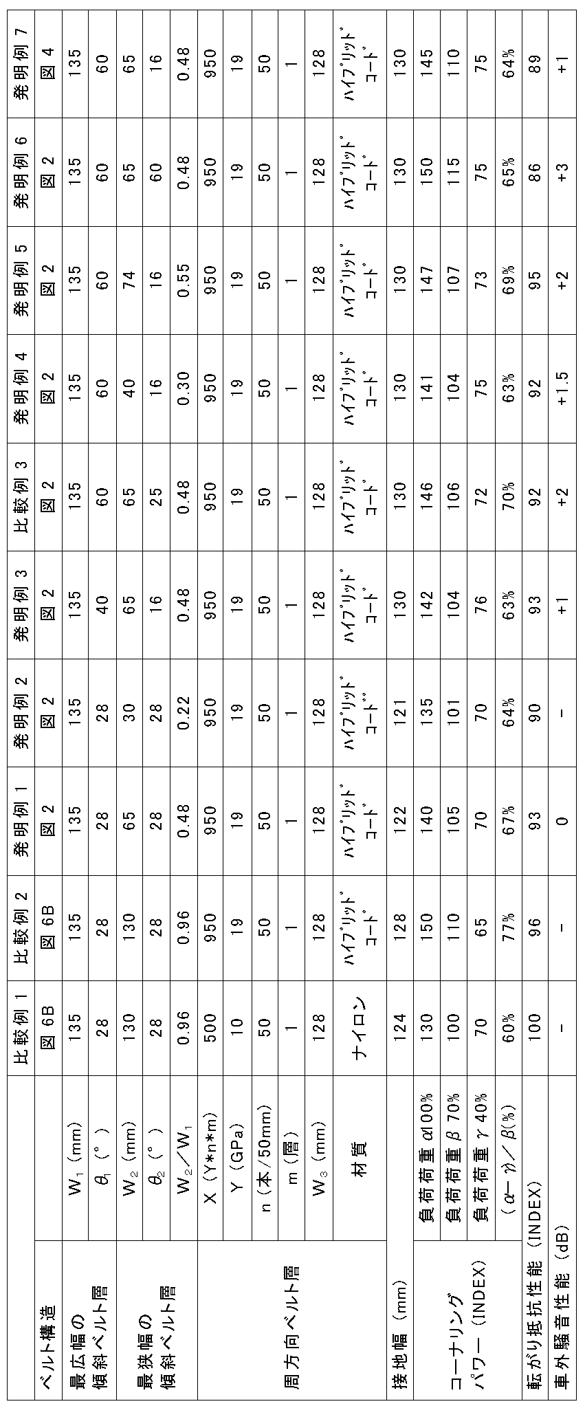
- invention tires and comparative tires (both tire sizes are 165 / 60R19) were prototyped under the specifications shown in Table 1, and the cornering power, rolling resistance performance, and noise resistance performance were evaluated.
- Each test tire has a carcass straddling a toroid between a pair of bead portions, and two inclined belt layers and one or more circumferential belt layers are provided on the outer side in the tire radial direction of the crown portion of the carcass.
- a tire including a belt having a tread and a tread.
Abstract
Description
(1)本発明のタイヤは、1対のビード部間にトロイド状に跨るカーカスと、該カーカスのクラウン部のタイヤ径方向外側に設けられた、タイヤ周方向に対し傾斜して延びるコードを有する傾斜ベルト層及び、タイヤ周方向に沿って延びるコードを有する周方向ベルト層と、を具えるタイヤであって、前記周方向ベルト層は、該周方向ベルト層をなすコードのヤング率(GPa)をY、幅50mmあたりの該コードの打ち込み本数をn、及び、該周方向ベルト層の層数をmとして、X=Y×n×mと定義するとき、X≧750を満たし、且つ、前記傾斜ベルト層は、タイヤ幅方向幅の異なる2層の傾斜ベルト層を少なくとも含み、最広幅の傾斜ベルト層のタイヤ幅方向幅W1と最狭幅の傾斜ベルト層のタイヤ幅方向幅W2とが、W2≦0.6W1を満たすことを特徴とする。 The gist of the present invention is as follows.
(1) The tire of the present invention has a carcass straddling in a toroidal shape between a pair of bead portions, and a cord provided on the outer side in the tire radial direction of the crown portion of the carcass and extending obliquely with respect to the tire circumferential direction. A tire comprising an inclined belt layer and a circumferential belt layer having a cord extending along a tire circumferential direction, wherein the circumferential belt layer is a Young's modulus (GPa) of a cord forming the circumferential belt layer Is defined as X = Y × n × m where Y is Y, the number of cords to be driven per width of 50 mm is n, and the number of layers of the circumferential belt layer is m, X ≧ 750 is satisfied, and The inclined belt layer includes at least two inclined belt layers having different widths in the tire width direction, the tire width direction width W 1 of the widest inclined belt layer, and the tire width direction width W 2 of the narrowest inclined belt layer; But W 2 ≦ 0.6W 1 It is characterized by satisfying.
また、ヤング率は、タイヤ周方向に対するヤング率を意味し、JIS L1017 8.5 a)(2002)にて試験を行い、JIS L1017 8.8(2002)に準拠して求めるものである。なお、ヤング率の測定は成形・加硫後のタイヤからコードを切りだし測定すればよい。 Note that “extends along the tire circumferential direction” means that the cord is tire circumferential depending on the case where the cord is parallel to the tire circumferential direction or the result of forming a belt layer by spirally winding a strip coated with rubber on the cord. The case where it is slightly inclined with respect to the direction (the inclination angle with respect to the tire circumferential direction is 5 ° or less) is included.
The Young's modulus means the Young's modulus with respect to the tire circumferential direction, and is obtained in accordance with JIS L1017 8.8 (2002) after testing according to JIS L1017 8.5 a) (2002). The Young's modulus may be measured by cutting the cord from the molded and vulcanized tire.
本発明における、傾斜ベルト層及び周方向ベルト層のタイヤ幅方向幅等は、タイヤを適用リムに装着し、JATMA等に記載されている適用サイズ・プライレーティングにおける最大負荷能力に対応する空気圧(以下、「所定空気圧」という)が充填され、無負荷の状態で測定するものとする。 Further, the tire of the present invention is mounted on an applicable rim for use. "Applicable rim" is an industrial standard that is valid for the region where tires are produced and used. Standard rim in size (Measuring Rim for STANDARDDS MANUAL of ETRTO, Design Rim for YEAR BOOK of TRA).
In the present invention, the width in the tire width direction of the inclined belt layer and the circumferential belt layer is the air pressure (hereinafter referred to as the maximum load capacity in the applied size / ply rating described in JATMA, etc., when the tire is mounted on the applied rim. , Referred to as “predetermined air pressure”), and measurement is performed under no load.
図1は、本発明の一実施形態に係るタイヤの幅方向断面を示す。このタイヤ10は、それぞれがビードコア1を具える1対のビード部11間にトロイド状に跨るカーカス2と、該カーカス2のクラウン部のタイヤ径方向外側に、タイヤ周方向に対し傾斜して延びるコードを有する傾斜ベルト層3(図示では、2層の傾斜ベルト層3w、3n)及び、タイヤ周方向に沿って延びるコードを有する周方向ベルト層4(図示では1層)からなるベルトBと、トレッド6と、を具える。より詳細には、2層の傾斜ベルト層3のタイヤ幅方向幅は相互に異なり、タイヤ幅方向幅W1を有する最広幅の傾斜ベルト層3wの外周側に、タイヤ幅方向幅W2を有する最狭幅の傾斜ベルト層3nが位置している。 Hereinafter, the tire of the present invention will be described in detail by exemplifying an embodiment thereof with reference to the drawings.
FIG. 1 shows a cross section in the width direction of a tire according to an embodiment of the present invention. The
X≧750を満たすよう上記要素を調整することにより、周方向ベルト層4の面内曲げ剛性、ひいてはタイヤのリング剛性が高まるため、コーナリングパワーを増大させることができる。 Here, in the tire of the present invention, when the Young's modulus (GPa) of the cord in the
By adjusting the above elements so as to satisfy X ≧ 750, the in-plane bending rigidity of the
そのため、上記関係式を満たした上で、タイヤ幅方向幅が相互に異なる2層の傾斜ベルト層を少なくとも有し、最広幅の傾斜ベルト層3wのタイヤ幅方向幅W1と最狭幅の傾斜ベルト層3nのタイヤ幅方向幅W2とが、W2≦0.6W1を満たすことが肝要である。 However, as described above, in the tire in which the ring rigidity is increased and the cornering power is increased as described above, the magnitude of the cornering power that is developed tends to depend on the load applied to the tire.
Therefore, while satisfying the above relationship, the tire width direction width has at least an inclined belt layers of mutually different two layers, tilt the tire width direction width W 1 of the widest of the
また、W2≦0.6W1とすれば、タイヤ重量が軽量化されるので、タイヤの転がり抵抗を低減することもできる。 The range of W 2 ≦ 0.6W 1 is that the tire width direction width W2 of the narrowest
Further, if W 2 ≦ 0.6W 1 , the tire weight is reduced, so that the rolling resistance of the tire can be reduced.
このような放射音は、60km以上の高速走行での使用も想定され、かつ顧客からの騒音性能の要求も高い乗用車用タイヤで特に課題となりうる。 However, when the inclination angle θ 1 of the cord of the widest
Such a radiated sound can be a problem particularly in a tire for a passenger car that is expected to be used at a high speed of 60 km or more and has a high demand for noise performance from customers.
また、図7に示すように、傾斜ベルト層3n、3wのコードの延在方向を同一方向にすると、2層の傾斜ベルト層間に働くせん断力が小さくなるため、転がり抵抗性能を特に良好にすることができる。 As shown in FIG. 2, when the extending directions of the cords of the
Further, as shown in FIG. 7, when the extending directions of the cords of the
このタイヤ20は、ビード部11間にトロイド状に跨るカーカス2のタイヤ径方向外側に、傾斜ベルト層3(図示では、2層の傾斜ベルト層3w、3n)、及び、周方向ベルト層4(図示では、タイヤ幅方向に分断された周方向ベルト層4a、4b)とからなるベルトBと、トレッド6とを具える。 Next, the tire width direction cross section of the tire which concerns on other embodiment of this invention is shown in FIG. Note that the description of the same points as in the above-described embodiment is omitted.
The
なお、複数層の周方向ベルト層が、図3に示すように相互に重複する場合、その重複部分のタイヤ幅方向長さAは30mm以内であることが、接地長の低減を抑制する観点から好ましい。ただし、タイヤ赤道面付近における周方向ベルト層を増やすと、周方向剛性を助長することで騒音性能を悪化させるもととなる振動モードを抑制することができるため、周方向ベルト層をタイヤ幅方向にわたってほぼ完全に重複させない範囲であれば、長さAを30mm以上としてもよい。 Thus, in the tire of the present invention, the number of circumferential belt layers in the vicinity of the tire equatorial plane can be made larger than the number of layers in other regions as necessary. This is mainly based on tire manufacturing advantages.
In addition, when a plurality of circumferential belt layers overlap each other as shown in FIG. 3, the tire width direction length A of the overlapping portion is within 30 mm from the viewpoint of suppressing the reduction of the contact length. preferable. However, increasing the circumferential belt layer in the vicinity of the tire equatorial plane can suppress the vibration mode that deteriorates the noise performance by promoting circumferential rigidity, so the circumferential belt layer is placed in the tire width direction. The length A may be 30 mm or more as long as it does not overlap almost completely.
なお、トレッド幅TWとは、タイヤを適用リムに装着し、所定空気圧を充填し、そこに最大負荷能力に対応する荷重を負荷したときの接地幅をいうものとする。 Further, the width W 3 in the tire width direction of the
The tread width TW refers to the contact width when a tire is mounted on an applicable rim, filled with a predetermined air pressure, and a load corresponding to the maximum load capacity is applied thereto.
上記の比および関係式を満たすタイヤ、すなわち従来通例の乗用車用空気入りタイヤよりも狭幅大径としたタイヤでは転がり抵抗が大幅に向上するものの、トレッドも狭幅であるためにコーナリングパワーが不足する傾向にあるところ、本発明の構成を適用することにより、好適に、コーナリングパワーを増大させることができる。 In the belt structure of the present invention, when the internal pressure is 250 kPa or more and the tire cross-sectional width SW is less than 165 mm, the ratio SW / OD of the tire cross-sectional width SW to the outer shape OD is 0.26. Yes, when the tire cross-sectional width SW is 165 mm or more, the tire cross-sectional width SW and the outer diameter OD are applied to a pneumatic radial tire for a passenger car that satisfies the relational expression, OD ≧ 2.135 × SW + 282.3. Is particularly preferred.
A tire that satisfies the above ratio and relational formula, that is, a tire having a narrower diameter and a larger diameter than conventional pneumatic tires for passenger cars, greatly improves rolling resistance, but the tread is also narrower, so cornering power is insufficient. However, the cornering power can be preferably increased by applying the configuration of the present invention.
発明例タイヤ及び比較例タイヤ(ともに、タイヤサイズは165/60R19)を表1に示す仕様のもと試作し、コーナリングパワー、転がり抵抗性能、及び耐騒音性能を評価した。
各供試タイヤは、1対のビード部間にトロイド状に跨るカーカスを有し、該カーカスのクラウン部のタイヤ径方向外側に、2層の傾斜ベルト層及び1層以上の周方向ベルト層を有するベルトと、トレッドとを具えるタイヤである。 Examples of the present invention will be described below.
Invention tires and comparative tires (both tire sizes are 165 / 60R19) were prototyped under the specifications shown in Table 1, and the cornering power, rolling resistance performance, and noise resistance performance were evaluated.
Each test tire has a carcass straddling a toroid between a pair of bead portions, and two inclined belt layers and one or more circumferential belt layers are provided on the outer side in the tire radial direction of the crown portion of the carcass. A tire including a belt having a tread and a tread.
各供試タイヤをリム(サイズは5.5J-19)に組み付け、内圧300kPaを付与した後、車両に装着し、フラットベルト式コーナリング試験機において測定を行った。なお、ベルト速度を100km/hとし、3つの異なる荷重条件下、すなわち、適用サイズ・プライレーティングにおける最大負荷能力に対応する荷重条件下、その70%にあたる荷重条件下、及び、同じく40%にあたる荷重条件下において得られるコーナリングパワーを測定した。
結果を表1に示す。結果は、比較例タイヤ1の負荷荷重70%における、タイヤのコーナリングパワーを100として指数評価したものである。なお、指数が大きいほど、コーナリングパワーが大きいことを示している。なお、表中の(α-γ)/β(%)を参照することで、コーナリングパワーの荷重依存性の高低が分かる。数値の小さい方が、荷重依存性が低いことを示している。 (Cornering power)
Each test tire was assembled on a rim (size 5.5J-19), applied with an internal pressure of 300 kPa, mounted on the vehicle, and measured with a flat belt cornering tester. The belt speed is set to 100 km / h, three different load conditions, that is, a load condition corresponding to the maximum load capacity in the application size / ply rating, a load condition corresponding to 70%, and a load corresponding to 40%. The cornering power obtained under the conditions was measured.
The results are shown in Table 1. The result is an index evaluation in which the cornering power of the tire at the load 70% of the
各供試タイヤを、上記と同様の条件のもと車両に装着し、走行試験用ドラム上で、該ドラムを100km/hの速度で回転させて転がり抵抗を測定した。結果を表1に示す。結果は、比較例タイヤ1の転がり抵抗を100として指数評価したものである。なお、指数が小さいほど、転がり抵抗性能に優れていることを示している。 (Rolling resistance performance)
Each test tire was mounted on a vehicle under the same conditions as described above, and the rolling resistance was measured by rotating the drum at a speed of 100 km / h on a running test drum. The results are shown in Table 1. The result is an index evaluation with the rolling resistance of
各供試タイヤを、上記と同様の条件のもと車両に装着し、走行試験用ドラム上で、該ドラムを100km/hの速度で回転させるとともに、マイク移動式でノイズ(騒音)レベルを測定した。結果を表1に示す。結果は、比較例タイヤ1とのノイズレベルの差をもって評価している。数値が小さい方が、騒音の低減効果に優れていることを意味する。 (External vehicle noise performance)
Each test tire is mounted on a vehicle under the same conditions as described above, and the drum is rotated at a speed of 100 km / h on the running test drum, and the noise level is measured by moving the microphone. did. The results are shown in Table 1. The result is evaluated based on the difference in noise level from the
2:カーカス
3、3´:傾斜ベルト層
3w:最広幅の傾斜ベルト層
3n:最狭幅の傾斜ベルト層
4、4´、4a、4b:周方向ベルト層
6:トレッド
10、20:タイヤ
11:ビード部
B:ベルト
CL:タイヤ赤道面
TE:トレッド端
TW:トレッド幅 1: Bead core 2:
Claims (4)
- 1対のビード部間にトロイド状に跨るカーカスと、該カーカスのクラウン部のタイヤ径方向外側に設けられた、タイヤ周方向に対し傾斜して延びるコードを有する傾斜ベルト層及び、タイヤ周方向に沿って延びるコードを有する周方向ベルト層と、を具えるタイヤであって、
前記周方向ベルト層は、該周方向ベルト層をなすコードのヤング率(GPa)をY、幅50mmあたりの該コードの打ち込み本数をn、及び、該周方向ベルト層の層数をmとして、
X=Y×n×m
と定義するとき、
X≧750
を満たし、
且つ、前記傾斜ベルト層は、タイヤ幅方向幅の異なる2層の傾斜ベルト層を少なくとも含み、最広幅の傾斜ベルト層のタイヤ幅方向幅W1と最狭幅の傾斜ベルト層のタイヤ幅方向幅W2とが、
W2≦0.6W1
を満たすことを特徴とするタイヤ。 A carcass straddling a toroid between a pair of bead portions, an inclined belt layer provided on the outer side in the tire radial direction of the crown portion of the carcass and having a cord extending inclined with respect to the tire circumferential direction; A tire comprising a circumferential belt layer having a cord extending therethrough,
In the circumferential belt layer, the Young's modulus (GPa) of the cord forming the circumferential belt layer is Y, the number of cords driven per width of 50 mm is n, and the number of layers of the circumferential belt layer is m.
X = Y × n × m
When defining
X ≧ 750
The filling,
And, wherein the inclined belt layer comprises at least a slant belt layers of different two layers of the tire width direction width, tire width direction width of the slant belt layer in the tire width direction width W 1 and the narrowest width of the widest of the slant belt layer W 2
W 2 ≦ 0.6W 1
A tire characterized by satisfying - W2≧0.25W1を満たす、請求項1に記載のタイヤ。 The tire according to claim 1 , wherein W 2 ≧ 0.25 W 1 is satisfied.
- 前記最広幅の傾斜ベルト層をなすコードのタイヤ周方向に対する傾斜角度θ1と、前記最狭幅の傾斜ベルト層におけるコードのタイヤ周方向に対する傾斜角度θ2とが、
30°≦θ1≦85°、
10°≦θ2≦30°、及び、
θ1>θ2
を満たす、請求項1または2に記載のタイヤ。 The inclination angle θ 1 with respect to the tire circumferential direction of the cord forming the widest inclined belt layer, and the inclination angle θ 2 with respect to the tire circumferential direction of the cord in the narrowest inclined belt layer,
30 ° ≦ θ 1 ≦ 85 °,
10 ° ≦ θ 2 ≦ 30 °, and
θ 1 > θ 2
The tire according to claim 1 or 2, satisfying - 前記傾斜ベルト層が、広幅の傾斜ベルト層と狭幅の傾斜ベルト層の2層のみからなる、請求項1~3のいずれか1項に記載のタイヤ。 The tire according to any one of claims 1 to 3, wherein the inclined belt layer comprises only two layers, a wide inclined belt layer and a narrow inclined belt layer.
Priority Applications (4)
| Application Number | Priority Date | Filing Date | Title |
|---|---|---|---|
| CN201480058993.6A CN105682939B (en) | 2013-10-29 | 2014-07-07 | Tire |
| US15/029,340 US10556466B2 (en) | 2013-10-29 | 2014-07-07 | Tire |
| EP14858143.2A EP3064376B1 (en) | 2013-10-29 | 2014-07-07 | Tire |
| JP2015544763A JP6393690B2 (en) | 2013-10-29 | 2014-07-07 | tire |
Applications Claiming Priority (2)
| Application Number | Priority Date | Filing Date | Title |
|---|---|---|---|
| JP2013-224530 | 2013-10-29 | ||
| JP2013224530 | 2013-10-29 |
Publications (1)
| Publication Number | Publication Date |
|---|---|
| WO2015063977A1 true WO2015063977A1 (en) | 2015-05-07 |
Family
ID=53003615
Family Applications (1)
| Application Number | Title | Priority Date | Filing Date |
|---|---|---|---|
| PCT/JP2014/003595 WO2015063977A1 (en) | 2013-10-29 | 2014-07-07 | Tire |
Country Status (5)
| Country | Link |
|---|---|
| US (1) | US10556466B2 (en) |
| EP (1) | EP3064376B1 (en) |
| JP (1) | JP6393690B2 (en) |
| CN (1) | CN105682939B (en) |
| WO (1) | WO2015063977A1 (en) |
Cited By (2)
| Publication number | Priority date | Publication date | Assignee | Title |
|---|---|---|---|---|
| JP2019162912A (en) * | 2018-03-19 | 2019-09-26 | 横浜ゴム株式会社 | Pneumatic tire |
| JP2020032888A (en) * | 2018-08-30 | 2020-03-05 | 横浜ゴム株式会社 | Pneumatic tire |
Families Citing this family (7)
| Publication number | Priority date | Publication date | Assignee | Title |
|---|---|---|---|---|
| CN105682940B (en) * | 2013-10-29 | 2018-03-06 | 株式会社普利司通 | Tire |
| WO2018125181A1 (en) * | 2016-12-30 | 2018-07-05 | Compagnie Generale Des Etablissements Michelin | Improved tire belt construction |
| JP6911513B2 (en) * | 2017-05-17 | 2021-07-28 | 住友ゴム工業株式会社 | Pneumatic tires |
| JP6989356B2 (en) * | 2017-11-09 | 2022-01-05 | Toyo Tire株式会社 | Pneumatic tires |
| JP7135867B2 (en) | 2017-12-22 | 2022-09-13 | 横浜ゴム株式会社 | run flat tires |
| JP6720997B2 (en) * | 2018-04-10 | 2020-07-08 | 横浜ゴム株式会社 | Run flat tires |
| CN108407551A (en) * | 2018-04-16 | 2018-08-17 | 中策橡胶集团有限公司 | A kind of low section all-steel radial tyre with 0 degree of winding of strips layer |
Citations (6)
| Publication number | Priority date | Publication date | Assignee | Title |
|---|---|---|---|---|
| JP2001301421A (en) * | 2000-04-21 | 2001-10-31 | Bridgestone Corp | Pneumatic tire |
| JP2003154808A (en) * | 2001-11-20 | 2003-05-27 | Bridgestone Corp | Pneumatic radial tire |
| JP2006193032A (en) * | 2005-01-13 | 2006-07-27 | Bridgestone Corp | Pneumatic tire |
| JP2007045334A (en) * | 2005-08-10 | 2007-02-22 | Yokohama Rubber Co Ltd:The | Flat pneumatic radial tire for heavy load |
| JP2009154685A (en) * | 2007-12-26 | 2009-07-16 | Bridgestone Corp | Tire |
| JP2012171423A (en) * | 2011-02-18 | 2012-09-10 | Bridgestone Corp | Pneumatic radial tire |
Family Cites Families (65)
| Publication number | Priority date | Publication date | Assignee | Title |
|---|---|---|---|---|
| NL253806A (en) * | 1959-11-10 | |||
| US3339610A (en) * | 1965-04-14 | 1967-09-05 | Pirelli | Pneumatic tires having asymmetrical structure |
| BE743656A (en) * | 1969-01-04 | 1970-05-28 | ||
| CH518192A (en) * | 1970-03-12 | 1972-01-31 | Pirelli | Tread ring for tread tire separated from the carcass |
| CA1014061A (en) * | 1974-12-28 | 1977-07-19 | Bridgestone Tire Company Limited | Pneumatic tires for off-road vehicles |
| JPS52131303A (en) * | 1976-04-28 | 1977-11-04 | Bridgestone Corp | Pneumatic radial tire having belts of coiled filament reinforcement layer |
| IT1081053B (en) * | 1976-05-17 | 1985-05-16 | Pirelli | IMPROVEMENT OF THE RESISTANT STRUCTURE OF TIRES FOR VEHICLE WHEELS |
| SE7807695L (en) * | 1978-07-10 | 1980-01-11 | Ifm Akustikbyran Ab | VEHICLE DECK |
| JPS60143106A (en) * | 1983-12-29 | 1985-07-29 | Bridgestone Corp | Pneumatic radial tire for heavy load |
| US5154217A (en) * | 1986-11-21 | 1992-10-13 | The Yokohama Rubber Co., Ltd. | Heavy-duty pneumatic tire preventing belt separation |
| JPS63235587A (en) * | 1986-11-25 | 1988-09-30 | 横浜ゴム株式会社 | Pneumatic tire for heavy load |
| US4869307A (en) * | 1988-03-17 | 1989-09-26 | The Goodyear Tire & Rubber Company | Pneumatic tire and method for making same |
| DE69004376T2 (en) * | 1989-08-10 | 1994-03-24 | Sumitomo Rubber Ind | Tire. |
| US5188685A (en) * | 1989-11-07 | 1993-02-23 | The Goodyear Tire & Rubber Company | Pneumatic radial tire including steel belt cords of 2+2x.30ht construction |
| JP2702835B2 (en) * | 1990-10-29 | 1998-01-26 | 住友ゴム工業株式会社 | Radial tires for motorcycles |
| JP3180166B2 (en) * | 1992-06-05 | 2001-06-25 | 横浜ゴム株式会社 | Pneumatic radial tire |
| JP2799322B2 (en) * | 1993-06-07 | 1998-09-17 | 住友ゴム工業株式会社 | Pneumatic tires for motorcycles |
| IT1273973B (en) * | 1995-02-27 | 1997-07-11 | Pirelli | TIRE WITH REINFORCED BELT BAND |
| IT1277400B1 (en) * | 1995-08-01 | 1997-11-10 | Pirelli | TIRE WITH HIGH TRANSVERSAL CURVATURE PARTICULARLY FOR TWO WHEEL VEHICLES |
| IT1283051B1 (en) * | 1996-05-22 | 1998-04-07 | Pirelli | PAIR OF HIGH TRANSVERSAL CURVATURE TIRES, ESPECIALLY FOR TWO-WHEELED VEHICLES AND METHOD FOR BEHAVIORAL CONTROL |
| IT1283351B1 (en) * | 1996-07-29 | 1998-04-17 | Pirelli | TIRE WITH HIGH TRANSVERSAL CURVATURE IN PARTICULAR FOR FRONT WHEELS |
| EP0908329B1 (en) * | 1997-10-06 | 2003-04-02 | PIRELLI PNEUMATICI Società per Azioni | Reinforcing fabric for an article made from elastometric material and corresponding article comprising this fabric |
| JP4264154B2 (en) | 1999-01-12 | 2009-05-13 | 株式会社ブリヂストン | Radial tire |
| FR2796005A1 (en) * | 1999-07-07 | 2001-01-12 | Michelin Soc Tech | Pneumatic tyre has tread with reinforcing fabric(s) having parallel reinforcement members at angle to circumferential direction and layer(s) of spirally wound textile reinforcements in circumferential direction |
| JP2002012004A (en) * | 2000-06-28 | 2002-01-15 | Sumitomo Rubber Ind Ltd | Pneumatic tire |
| JP4635366B2 (en) * | 2001-04-12 | 2011-02-23 | 横浜ゴム株式会社 | Pneumatic radial tire |
| WO2003061991A1 (en) * | 2002-01-24 | 2003-07-31 | Bridgestone Corporation | Pneumatic radial tire, and method of producing the same |
| WO2004076205A1 (en) * | 2003-02-17 | 2004-09-10 | Societe De Technologie Michelin | Crown reinforcement for a radial tyre |
| FR2857621B1 (en) * | 2003-07-18 | 2005-08-19 | Michelin Soc Tech | PNEUMATIC FOR HEAVY VEHICLES |
| JP4315820B2 (en) | 2004-01-07 | 2009-08-19 | 株式会社ブリヂストン | Pneumatic tires for motorcycles |
| US20090008017A1 (en) * | 2005-01-13 | 2009-01-08 | Bridgestone Corporation | Pneumatic Tire |
| JP2007168711A (en) * | 2005-12-26 | 2007-07-05 | Bridgestone Corp | Pneumatic radial tire for heavy load |
| US20070221309A1 (en) * | 2006-03-27 | 2007-09-27 | Cohen Martin P | Tire having belt ply edge protector |
| JP4771923B2 (en) * | 2006-11-24 | 2011-09-14 | 株式会社ブリヂストン | Pneumatic tire |
| JP2008149990A (en) * | 2006-12-20 | 2008-07-03 | Bridgestone Corp | Pneumatic tire for two-wheeler |
| JP2008149992A (en) * | 2006-12-20 | 2008-07-03 | Bridgestone Corp | Pneumatic tire for two-wheeler |
| JP5164453B2 (en) * | 2007-07-03 | 2013-03-21 | 株式会社ブリヂストン | Pneumatic tire |
| FR2921863B1 (en) * | 2007-10-05 | 2009-12-18 | Michelin Soc Tech | PNEUMATIC USING A FIBER REINFORCING STRUCTURE OF APLATIE SECTION |
| JP4316641B2 (en) * | 2007-11-30 | 2009-08-19 | 横浜ゴム株式会社 | Pneumatic radial tire |
| JP4335278B2 (en) * | 2007-12-14 | 2009-09-30 | 住友ゴム工業株式会社 | Pneumatic tire manufacturing method and pneumatic tire |
| WO2011016215A1 (en) | 2009-08-05 | 2011-02-10 | 株式会社ブリヂストン | Pneumatic tire |
| IT1394572B1 (en) * | 2009-07-03 | 2012-07-05 | Pirellityre Spa | TIRE FOR MOTOR VEHICLES OFF-ROAD |
| US8813804B2 (en) * | 2009-07-30 | 2014-08-26 | Compagnie Generale Des Etablissements Michelin | Tire for heavy goods vehicle having a reinforced bead |
| JP6042719B2 (en) | 2010-06-21 | 2016-12-14 | 株式会社ブリヂストン | Pneumatic radial tire for passenger cars |
| JP5735810B2 (en) * | 2011-01-14 | 2015-06-17 | 株式会社ブリヂストン | Pneumatic tire and method for forming circumferential belt layer in pneumatic tire |
| JPWO2012176476A1 (en) * | 2011-06-22 | 2015-02-23 | 株式会社ブリヂストン | Pneumatic radial tire for passenger cars, method of using the tire, and tire / rim assembly including the tire |
| JP4911267B1 (en) | 2011-08-10 | 2012-04-04 | 横浜ゴム株式会社 | Pneumatic tire |
| JP5045852B1 (en) * | 2011-09-02 | 2012-10-10 | 横浜ゴム株式会社 | Pneumatic tire |
| DE112011105654B4 (en) * | 2011-09-22 | 2018-07-19 | The Yokohama Rubber Co., Ltd. | tire |
| KR101258195B1 (en) * | 2011-09-22 | 2013-04-25 | 요코하마 고무 가부시키가이샤 | Pneumatic tire |
| US9045004B2 (en) * | 2011-09-22 | 2015-06-02 | The Yokohama Rubber Co., Ltd. | Pneumatic tire |
| EP2774780B1 (en) | 2011-11-02 | 2016-04-27 | Bridgestone Corporation | Pneumatic radial tire for passenger car |
| FR2983778B1 (en) * | 2011-12-09 | 2014-08-01 | Michelin Soc Tech | PNEUMATIC COMPRISING A LAYER OF CIRCUMFERENTIAL REINFORCING ELEMENTS |
| WO2013125117A1 (en) * | 2012-02-22 | 2013-08-29 | 住友ゴム工業株式会社 | Pneumatic tire |
| US9849730B2 (en) * | 2012-07-13 | 2017-12-26 | The Yokohama Rubber Co., Ltd. | Pneumatic tire |
| US10369845B2 (en) * | 2012-10-10 | 2019-08-06 | The Yokohama Rubber Co., Ltd. | Pneumatic tire |
| KR20150074024A (en) * | 2012-10-18 | 2015-07-01 | 코드사 글로벌 엔두스트리옐 이플릭 베 코드 베지 사나위 베 티카레트 아노님 시르케티 | A reinforcing belt package for radial vehicle tires |
| WO2014103063A1 (en) * | 2012-12-28 | 2014-07-03 | 横浜ゴム株式会社 | Pneumatic tire |
| JP5525073B1 (en) * | 2013-02-06 | 2014-06-18 | 株式会社ブリヂストン | Heavy duty tire |
| JP5756486B2 (en) * | 2013-03-12 | 2015-07-29 | 住友ゴム工業株式会社 | Pneumatic tire |
| JP5486109B1 (en) * | 2013-05-10 | 2014-05-07 | 株式会社ブリヂストン | Tire and manufacturing method thereof |
| CN105682941B (en) * | 2013-10-29 | 2018-10-12 | 株式会社普利司通 | Pneumatic tire |
| CN105682940B (en) * | 2013-10-29 | 2018-03-06 | 株式会社普利司通 | Tire |
| JP6442228B2 (en) * | 2014-10-29 | 2018-12-19 | 株式会社ブリヂストン | Pneumatic tires for passenger cars |
| FR3033287B1 (en) * | 2015-03-05 | 2017-03-10 | Michelin & Cie | PNEUMATIC TOP REINFORCING FOR HEAVY VEHICLE TYPE GENIE CIVIL |
-
2014
- 2014-07-07 EP EP14858143.2A patent/EP3064376B1/en active Active
- 2014-07-07 CN CN201480058993.6A patent/CN105682939B/en active Active
- 2014-07-07 US US15/029,340 patent/US10556466B2/en active Active
- 2014-07-07 JP JP2015544763A patent/JP6393690B2/en active Active
- 2014-07-07 WO PCT/JP2014/003595 patent/WO2015063977A1/en active Application Filing
Patent Citations (6)
| Publication number | Priority date | Publication date | Assignee | Title |
|---|---|---|---|---|
| JP2001301421A (en) * | 2000-04-21 | 2001-10-31 | Bridgestone Corp | Pneumatic tire |
| JP2003154808A (en) * | 2001-11-20 | 2003-05-27 | Bridgestone Corp | Pneumatic radial tire |
| JP2006193032A (en) * | 2005-01-13 | 2006-07-27 | Bridgestone Corp | Pneumatic tire |
| JP2007045334A (en) * | 2005-08-10 | 2007-02-22 | Yokohama Rubber Co Ltd:The | Flat pneumatic radial tire for heavy load |
| JP2009154685A (en) * | 2007-12-26 | 2009-07-16 | Bridgestone Corp | Tire |
| JP2012171423A (en) * | 2011-02-18 | 2012-09-10 | Bridgestone Corp | Pneumatic radial tire |
Non-Patent Citations (1)
| Title |
|---|
| See also references of EP3064376A4 * |
Cited By (4)
| Publication number | Priority date | Publication date | Assignee | Title |
|---|---|---|---|---|
| JP2019162912A (en) * | 2018-03-19 | 2019-09-26 | 横浜ゴム株式会社 | Pneumatic tire |
| JP7031401B2 (en) | 2018-03-19 | 2022-03-08 | 横浜ゴム株式会社 | Pneumatic tires |
| JP2020032888A (en) * | 2018-08-30 | 2020-03-05 | 横浜ゴム株式会社 | Pneumatic tire |
| JP7107104B2 (en) | 2018-08-30 | 2022-07-27 | 横浜ゴム株式会社 | pneumatic tire |
Also Published As
| Publication number | Publication date |
|---|---|
| JP6393690B2 (en) | 2018-09-19 |
| EP3064376A4 (en) | 2016-11-09 |
| EP3064376B1 (en) | 2018-10-24 |
| US10556466B2 (en) | 2020-02-11 |
| JPWO2015063977A1 (en) | 2017-03-09 |
| CN105682939A (en) | 2016-06-15 |
| CN105682939B (en) | 2018-10-19 |
| US20160257168A1 (en) | 2016-09-08 |
| EP3064376A1 (en) | 2016-09-07 |
Similar Documents
| Publication | Publication Date | Title |
|---|---|---|
| JP6393690B2 (en) | tire | |
| JP6537496B2 (en) | Pneumatic tire | |
| JP6138663B2 (en) | tire | |
| JP6175427B2 (en) | Pneumatic tire | |
| JP5702421B2 (en) | Heavy duty pneumatic tire | |
| JP6450321B2 (en) | tire | |
| JP6450320B2 (en) | Pneumatic tire | |
| JP5628946B2 (en) | Heavy duty tire | |
| JP5257185B2 (en) | Pneumatic tire | |
| JP6450111B2 (en) | Pneumatic tire | |
| WO2016051685A1 (en) | Pneumatic tire for heavy loads | |
| JP2014168976A (en) | Pneumatic tire | |
| WO2023105830A1 (en) | Pneumatic radial tire for passenger vehicle | |
| WO2023105828A1 (en) | Pneumatic radial tire for passenger vehicle | |
| WO2023105831A1 (en) | Pneumatic radial tire for passenger car | |
| WO2023105829A1 (en) | Pneumatic radial tire for passenger car | |
| WO2023105832A1 (en) | Pneumatic radial tire for passenger vehicle | |
| JP2012056326A (en) | Pneumatic radial tire | |
| JP5823795B2 (en) | Heavy duty pneumatic radial tire | |
| WO2023105827A1 (en) | Pneumatic radial tire for passenger vehicle | |
| JP2011111006A (en) | Pneumatic radial tire for heavy load | |
| JP6185610B2 (en) | tire | |
| JP6489917B2 (en) | Pneumatic tire | |
| JP6204938B2 (en) | Pneumatic tire | |
| JP2011110998A (en) | Pneumatic radial tire for heavy load |
Legal Events
| Date | Code | Title | Description |
|---|---|---|---|
| 121 | Ep: the epo has been informed by wipo that ep was designated in this application |
Ref document number: 14858143 Country of ref document: EP Kind code of ref document: A1 |
|
| ENP | Entry into the national phase |
Ref document number: 2015544763 Country of ref document: JP Kind code of ref document: A |
|
| WWE | Wipo information: entry into national phase |
Ref document number: 15029340 Country of ref document: US |
|
| REEP | Request for entry into the european phase |
Ref document number: 2014858143 Country of ref document: EP |
|
| WWE | Wipo information: entry into national phase |
Ref document number: 2014858143 Country of ref document: EP |
|
| NENP | Non-entry into the national phase |
Ref country code: DE |