JP6450320B2 - Pneumatic tire - Google Patents
Pneumatic tire Download PDFInfo
- Publication number
- JP6450320B2 JP6450320B2 JP2015544762A JP2015544762A JP6450320B2 JP 6450320 B2 JP6450320 B2 JP 6450320B2 JP 2015544762 A JP2015544762 A JP 2015544762A JP 2015544762 A JP2015544762 A JP 2015544762A JP 6450320 B2 JP6450320 B2 JP 6450320B2
- Authority
- JP
- Japan
- Prior art keywords
- tire
- belt layer
- circumferential
- inclined belt
- width direction
- Prior art date
- Legal status (The legal status is an assumption and is not a legal conclusion. Google has not performed a legal analysis and makes no representation as to the accuracy of the status listed.)
- Expired - Fee Related
Links
Images


Classifications
-
- B—PERFORMING OPERATIONS; TRANSPORTING
- B60—VEHICLES IN GENERAL
- B60C—VEHICLE TYRES; TYRE INFLATION; TYRE CHANGING; CONNECTING VALVES TO INFLATABLE ELASTIC BODIES IN GENERAL; DEVICES OR ARRANGEMENTS RELATED TO TYRES
- B60C9/00—Reinforcements or ply arrangement of pneumatic tyres
- B60C9/18—Structure or arrangement of belts or breakers, crown-reinforcing or cushioning layers
- B60C9/20—Structure or arrangement of belts or breakers, crown-reinforcing or cushioning layers built-up from rubberised plies each having all cords arranged substantially parallel
-
- B—PERFORMING OPERATIONS; TRANSPORTING
- B60—VEHICLES IN GENERAL
- B60C—VEHICLE TYRES; TYRE INFLATION; TYRE CHANGING; CONNECTING VALVES TO INFLATABLE ELASTIC BODIES IN GENERAL; DEVICES OR ARRANGEMENTS RELATED TO TYRES
- B60C11/00—Tyre tread bands; Tread patterns; Anti-skid inserts
- B60C11/02—Replaceable treads
-
- B—PERFORMING OPERATIONS; TRANSPORTING
- B60—VEHICLES IN GENERAL
- B60C—VEHICLE TYRES; TYRE INFLATION; TYRE CHANGING; CONNECTING VALVES TO INFLATABLE ELASTIC BODIES IN GENERAL; DEVICES OR ARRANGEMENTS RELATED TO TYRES
- B60C11/00—Tyre tread bands; Tread patterns; Anti-skid inserts
- B60C11/03—Tread patterns
-
- B—PERFORMING OPERATIONS; TRANSPORTING
- B60—VEHICLES IN GENERAL
- B60C—VEHICLE TYRES; TYRE INFLATION; TYRE CHANGING; CONNECTING VALVES TO INFLATABLE ELASTIC BODIES IN GENERAL; DEVICES OR ARRANGEMENTS RELATED TO TYRES
- B60C15/00—Tyre beads, e.g. ply turn-up or overlap
-
- B—PERFORMING OPERATIONS; TRANSPORTING
- B60—VEHICLES IN GENERAL
- B60C—VEHICLE TYRES; TYRE INFLATION; TYRE CHANGING; CONNECTING VALVES TO INFLATABLE ELASTIC BODIES IN GENERAL; DEVICES OR ARRANGEMENTS RELATED TO TYRES
- B60C15/00—Tyre beads, e.g. ply turn-up or overlap
- B60C15/0009—Tyre beads, e.g. ply turn-up or overlap features of the carcass terminal portion
- B60C15/0036—Tyre beads, e.g. ply turn-up or overlap features of the carcass terminal portion with high ply turn-up, i.e. folded around the bead core and terminating radially above the point of maximum section width
- B60C15/0045—Tyre beads, e.g. ply turn-up or overlap features of the carcass terminal portion with high ply turn-up, i.e. folded around the bead core and terminating radially above the point of maximum section width with ply turn-up up to the belt edges, i.e. folded around the bead core and extending to the belt edges
-
- B—PERFORMING OPERATIONS; TRANSPORTING
- B60—VEHICLES IN GENERAL
- B60C—VEHICLE TYRES; TYRE INFLATION; TYRE CHANGING; CONNECTING VALVES TO INFLATABLE ELASTIC BODIES IN GENERAL; DEVICES OR ARRANGEMENTS RELATED TO TYRES
- B60C9/00—Reinforcements or ply arrangement of pneumatic tyres
- B60C9/02—Carcasses
-
- B—PERFORMING OPERATIONS; TRANSPORTING
- B60—VEHICLES IN GENERAL
- B60C—VEHICLE TYRES; TYRE INFLATION; TYRE CHANGING; CONNECTING VALVES TO INFLATABLE ELASTIC BODIES IN GENERAL; DEVICES OR ARRANGEMENTS RELATED TO TYRES
- B60C9/00—Reinforcements or ply arrangement of pneumatic tyres
- B60C9/18—Structure or arrangement of belts or breakers, crown-reinforcing or cushioning layers
- B60C9/20—Structure or arrangement of belts or breakers, crown-reinforcing or cushioning layers built-up from rubberised plies each having all cords arranged substantially parallel
- B60C9/2003—Structure or arrangement of belts or breakers, crown-reinforcing or cushioning layers built-up from rubberised plies each having all cords arranged substantially parallel characterised by the materials of the belt cords
- B60C9/2009—Structure or arrangement of belts or breakers, crown-reinforcing or cushioning layers built-up from rubberised plies each having all cords arranged substantially parallel characterised by the materials of the belt cords comprising plies of different materials
-
- B—PERFORMING OPERATIONS; TRANSPORTING
- B60—VEHICLES IN GENERAL
- B60C—VEHICLE TYRES; TYRE INFLATION; TYRE CHANGING; CONNECTING VALVES TO INFLATABLE ELASTIC BODIES IN GENERAL; DEVICES OR ARRANGEMENTS RELATED TO TYRES
- B60C9/00—Reinforcements or ply arrangement of pneumatic tyres
- B60C9/18—Structure or arrangement of belts or breakers, crown-reinforcing or cushioning layers
- B60C9/28—Structure or arrangement of belts or breakers, crown-reinforcing or cushioning layers characterised by the belt or breaker dimensions or curvature relative to carcass
-
- B—PERFORMING OPERATIONS; TRANSPORTING
- B60—VEHICLES IN GENERAL
- B60C—VEHICLE TYRES; TYRE INFLATION; TYRE CHANGING; CONNECTING VALVES TO INFLATABLE ELASTIC BODIES IN GENERAL; DEVICES OR ARRANGEMENTS RELATED TO TYRES
- B60C11/00—Tyre tread bands; Tread patterns; Anti-skid inserts
- B60C11/03—Tread patterns
- B60C11/04—Tread patterns in which the raised area of the pattern consists only of continuous circumferential ribs, e.g. zig-zag
-
- B—PERFORMING OPERATIONS; TRANSPORTING
- B60—VEHICLES IN GENERAL
- B60C—VEHICLE TYRES; TYRE INFLATION; TYRE CHANGING; CONNECTING VALVES TO INFLATABLE ELASTIC BODIES IN GENERAL; DEVICES OR ARRANGEMENTS RELATED TO TYRES
- B60C9/00—Reinforcements or ply arrangement of pneumatic tyres
- B60C9/18—Structure or arrangement of belts or breakers, crown-reinforcing or cushioning layers
- B60C9/20—Structure or arrangement of belts or breakers, crown-reinforcing or cushioning layers built-up from rubberised plies each having all cords arranged substantially parallel
- B60C2009/2012—Structure or arrangement of belts or breakers, crown-reinforcing or cushioning layers built-up from rubberised plies each having all cords arranged substantially parallel with particular configuration of the belt cords in the respective belt layers
- B60C2009/2016—Structure or arrangement of belts or breakers, crown-reinforcing or cushioning layers built-up from rubberised plies each having all cords arranged substantially parallel with particular configuration of the belt cords in the respective belt layers comprising cords at an angle of 10 to 30 degrees to the circumferential direction
-
- B—PERFORMING OPERATIONS; TRANSPORTING
- B60—VEHICLES IN GENERAL
- B60C—VEHICLE TYRES; TYRE INFLATION; TYRE CHANGING; CONNECTING VALVES TO INFLATABLE ELASTIC BODIES IN GENERAL; DEVICES OR ARRANGEMENTS RELATED TO TYRES
- B60C9/00—Reinforcements or ply arrangement of pneumatic tyres
- B60C9/18—Structure or arrangement of belts or breakers, crown-reinforcing or cushioning layers
- B60C9/20—Structure or arrangement of belts or breakers, crown-reinforcing or cushioning layers built-up from rubberised plies each having all cords arranged substantially parallel
- B60C2009/2012—Structure or arrangement of belts or breakers, crown-reinforcing or cushioning layers built-up from rubberised plies each having all cords arranged substantially parallel with particular configuration of the belt cords in the respective belt layers
- B60C2009/2019—Structure or arrangement of belts or breakers, crown-reinforcing or cushioning layers built-up from rubberised plies each having all cords arranged substantially parallel with particular configuration of the belt cords in the respective belt layers comprising cords at an angle of 30 to 60 degrees to the circumferential direction
-
- B—PERFORMING OPERATIONS; TRANSPORTING
- B60—VEHICLES IN GENERAL
- B60C—VEHICLE TYRES; TYRE INFLATION; TYRE CHANGING; CONNECTING VALVES TO INFLATABLE ELASTIC BODIES IN GENERAL; DEVICES OR ARRANGEMENTS RELATED TO TYRES
- B60C9/00—Reinforcements or ply arrangement of pneumatic tyres
- B60C9/18—Structure or arrangement of belts or breakers, crown-reinforcing or cushioning layers
- B60C9/20—Structure or arrangement of belts or breakers, crown-reinforcing or cushioning layers built-up from rubberised plies each having all cords arranged substantially parallel
- B60C2009/2012—Structure or arrangement of belts or breakers, crown-reinforcing or cushioning layers built-up from rubberised plies each having all cords arranged substantially parallel with particular configuration of the belt cords in the respective belt layers
- B60C2009/2022—Structure or arrangement of belts or breakers, crown-reinforcing or cushioning layers built-up from rubberised plies each having all cords arranged substantially parallel with particular configuration of the belt cords in the respective belt layers comprising cords at an angle of 60 to 90 degrees to the circumferential direction
-
- B—PERFORMING OPERATIONS; TRANSPORTING
- B60—VEHICLES IN GENERAL
- B60C—VEHICLE TYRES; TYRE INFLATION; TYRE CHANGING; CONNECTING VALVES TO INFLATABLE ELASTIC BODIES IN GENERAL; DEVICES OR ARRANGEMENTS RELATED TO TYRES
- B60C9/00—Reinforcements or ply arrangement of pneumatic tyres
- B60C9/18—Structure or arrangement of belts or breakers, crown-reinforcing or cushioning layers
- B60C9/20—Structure or arrangement of belts or breakers, crown-reinforcing or cushioning layers built-up from rubberised plies each having all cords arranged substantially parallel
- B60C9/22—Structure or arrangement of belts or breakers, crown-reinforcing or cushioning layers built-up from rubberised plies each having all cords arranged substantially parallel the plies being arranged with all cords disposed along the circumference of the tyre
- B60C2009/2228—Structure or arrangement of belts or breakers, crown-reinforcing or cushioning layers built-up from rubberised plies each having all cords arranged substantially parallel the plies being arranged with all cords disposed along the circumference of the tyre characterised by special physical properties of the zero degree plies
- B60C2009/2233—Modulus of the zero degree ply
-
- B—PERFORMING OPERATIONS; TRANSPORTING
- B60—VEHICLES IN GENERAL
- B60C—VEHICLE TYRES; TYRE INFLATION; TYRE CHANGING; CONNECTING VALVES TO INFLATABLE ELASTIC BODIES IN GENERAL; DEVICES OR ARRANGEMENTS RELATED TO TYRES
- B60C9/00—Reinforcements or ply arrangement of pneumatic tyres
- B60C9/18—Structure or arrangement of belts or breakers, crown-reinforcing or cushioning layers
- B60C9/20—Structure or arrangement of belts or breakers, crown-reinforcing or cushioning layers built-up from rubberised plies each having all cords arranged substantially parallel
- B60C9/22—Structure or arrangement of belts or breakers, crown-reinforcing or cushioning layers built-up from rubberised plies each having all cords arranged substantially parallel the plies being arranged with all cords disposed along the circumference of the tyre
- B60C2009/2252—Physical properties or dimension of the zero degree ply cords
- B60C2009/2261—Modulus of the cords
-
- B—PERFORMING OPERATIONS; TRANSPORTING
- B60—VEHICLES IN GENERAL
- B60C—VEHICLE TYRES; TYRE INFLATION; TYRE CHANGING; CONNECTING VALVES TO INFLATABLE ELASTIC BODIES IN GENERAL; DEVICES OR ARRANGEMENTS RELATED TO TYRES
- B60C9/00—Reinforcements or ply arrangement of pneumatic tyres
- B60C9/18—Structure or arrangement of belts or breakers, crown-reinforcing or cushioning layers
- B60C9/20—Structure or arrangement of belts or breakers, crown-reinforcing or cushioning layers built-up from rubberised plies each having all cords arranged substantially parallel
- B60C9/22—Structure or arrangement of belts or breakers, crown-reinforcing or cushioning layers built-up from rubberised plies each having all cords arranged substantially parallel the plies being arranged with all cords disposed along the circumference of the tyre
- B60C2009/2252—Physical properties or dimension of the zero degree ply cords
- B60C2009/2266—Density of the cords in width direction
-
- B—PERFORMING OPERATIONS; TRANSPORTING
- B60—VEHICLES IN GENERAL
- B60C—VEHICLE TYRES; TYRE INFLATION; TYRE CHANGING; CONNECTING VALVES TO INFLATABLE ELASTIC BODIES IN GENERAL; DEVICES OR ARRANGEMENTS RELATED TO TYRES
- B60C11/00—Tyre tread bands; Tread patterns; Anti-skid inserts
- B60C11/03—Tread patterns
- B60C2011/0337—Tread patterns characterised by particular design features of the pattern
- B60C2011/0339—Grooves
- B60C2011/0341—Circumferential grooves
- B60C2011/0353—Circumferential grooves characterised by width
-
- B—PERFORMING OPERATIONS; TRANSPORTING
- B60—VEHICLES IN GENERAL
- B60C—VEHICLE TYRES; TYRE INFLATION; TYRE CHANGING; CONNECTING VALVES TO INFLATABLE ELASTIC BODIES IN GENERAL; DEVICES OR ARRANGEMENTS RELATED TO TYRES
- B60C9/00—Reinforcements or ply arrangement of pneumatic tyres
- B60C9/18—Structure or arrangement of belts or breakers, crown-reinforcing or cushioning layers
- B60C9/20—Structure or arrangement of belts or breakers, crown-reinforcing or cushioning layers built-up from rubberised plies each having all cords arranged substantially parallel
- B60C9/22—Structure or arrangement of belts or breakers, crown-reinforcing or cushioning layers built-up from rubberised plies each having all cords arranged substantially parallel the plies being arranged with all cords disposed along the circumference of the tyre
Landscapes
- Engineering & Computer Science (AREA)
- Mechanical Engineering (AREA)
- Tires In General (AREA)
Description
本出願は、2013年10月29日に日本国に特許出願された特願2013−224539の優先権を主張するものであり、この先の出願の開示全体をここに参照のために取り込む。 This application claims the priority of Japanese Patent Application No. 2013-224539 filed in Japan on October 29, 2013, the entire disclosure of which is incorporated herein by reference.
本発明は、空気入りタイヤに関するものである。 The present invention relates to a pneumatic tire.
従来、空気入りタイヤの補強として、ビード部間に跨るカーカスのクラウン部のタイヤ径方向外側に、タイヤ周方向に対して傾斜して延びるコードを有する傾斜ベルト層と、タイヤ周方向に沿って延びるコードを有する周方向ベルト層と、を配設することが知られている。 Conventionally, as a reinforcement of a pneumatic tire, an inclined belt layer having a cord extending obliquely with respect to the tire circumferential direction on the outer side in the tire radial direction of the crown portion of the carcass straddling between the bead portions, and extending along the tire circumferential direction It is known to provide a circumferential belt layer having a cord.
すなわち、傾斜ベルト層によりタイヤ幅方向の剛性を確保して、操縦安定性の重要な指標の1つであるコーナリングパワーを得るとともに、周方向ベルト層によりタイヤ周方向の剛性を確保して、高速走行時のタイヤの径成長を抑えることなどが行われている。 That is, the rigidity in the tire width direction is ensured by the inclined belt layer to obtain cornering power which is one of the important indicators of steering stability, and the rigidity in the tire circumferential direction is ensured by the circumferential belt layer to achieve high speed. It has been done to suppress the tire diameter growth during driving.
一般に、コーナリングパワーの大きいタイヤの方が操縦安定性にすぐれることから、その増大が望まれている。コーナリングパワーを増大させるには、傾斜ベルト層のタイヤ幅方向の剛性を高めることが有効であり、具体的には、傾斜ベルト層のコードをタイヤ周方向に対して大きく傾斜させることが考えられる。 In general, a tire having a large cornering power is superior in handling stability, and therefore, an increase in the tire is desired. In order to increase the cornering power, it is effective to increase the rigidity of the inclined belt layer in the tire width direction. Specifically, it is conceivable that the cord of the inclined belt layer is greatly inclined with respect to the tire circumferential direction.
タイヤ周方向に対して大きく傾斜させたコードを有する傾斜ベルト層を配設したタイヤでは、タイヤのスリップアングルが比較的大きい走行条件下では大きなコーナリングパワーが発生する。一方で、スリップアングルが比較的小さい走行条件ではコーナリングパワーの増大量が、スリップアングルが大きいときに比べて、少ないところに改善が要求されていた。 In a tire provided with an inclined belt layer having a cord that is largely inclined with respect to the tire circumferential direction, a large cornering power is generated under traveling conditions in which the tire slip angle is relatively large. On the other hand, the improvement of the cornering power is required to be small in the driving condition where the slip angle is relatively small compared to when the slip angle is large.
したがって、かかる事情に鑑みてなされた本発明は、タイヤのスリップアングルが変化する様々な走行条件下において確実にコーナリングパワーを向上させる空気入りタイヤを提供することを目的とする。 Accordingly, an object of the present invention made in view of such circumstances is to provide a pneumatic tire that reliably improves cornering power under various traveling conditions in which the slip angle of the tire changes.
上述した諸課題を解決すべく、本発明の空気入りタイヤは、1対のビード部およびトレッド部を含んで構成され、前記1対のビード部間に跨るカーカスと、カーカスのクラウン部のタイヤ径方向外側に配置されるとともにタイヤ周方向に対して傾斜するコードを有する少なくとも1層の傾斜ベルト層からなる傾斜ベルトと、カーカスのクラウン部のタイヤ径方向外側に配置されるとともにタイヤ周方向に沿って延びるコードを有する少なくとも1層の周方向ベルト層からなる周方向ベルトとを備える空気入りタイヤであって、トレッド部踏面には、タイヤ周方向に沿って延びる少なくとも1本の周方向主溝が設けられ、傾斜ベルトは、少なくとも1層の傾斜ベルト層として、コードのタイヤ周方向に対する傾斜角度が35°以上90°以下である高角度傾斜ベルト層を含み、少なくとも一方のトレッド半部において、最もタイヤ幅方向外側に配置された周方向主溝よりも高角度傾斜ベルト層のタイヤ幅方向端縁がタイヤ幅方向外側に位置し、該周方向主溝の中心から該端縁までのタイヤ幅方向間隔が、高角度傾斜ベルト層のタイヤ幅方向幅をW1として、0.2W1以上0.35W1以下であることを特徴とする。このような構成によれば、タイヤのスリップアングルが変化する様々な走行条件下においてコーナリングパワーを向上可能である。なお、トレッド半部とは、タイヤ赤道とトレッド端とにより区画される一対の領域である。In order to solve the above-described problems, the pneumatic tire of the present invention includes a pair of bead portions and a tread portion, and a tire diameter of a carcass straddling between the pair of bead portions and a crown portion of the carcass. An inclined belt comprising at least one inclined belt layer having a cord that is disposed on the outer side in the tire direction and inclined with respect to the tire circumferential direction, and disposed on the outer side in the tire radial direction of the crown portion of the carcass and along the tire circumferential direction A pneumatic tire comprising at least one circumferential belt layer having a cord extending in the tread portion, wherein at least one circumferential main groove extending along the tire circumferential direction is formed on the tread surface. The inclined belt is provided as at least one inclined belt layer, and the inclination angle of the cord with respect to the tire circumferential direction is 35 ° or more and 90 ° or less In the at least one half of the tread, the edge in the tire width direction of the high angle tilt belt layer is located on the outer side in the tire width direction than the circumferential main groove arranged on the outermost side in the tire width direction. and, the tire width direction distance from the center of the peripheral direction main groove to the said end edge, a tire width direction width of the high angle slant belt layer as W 1, is 0.2 W 1 or 0.35 W 1 or less Features. According to such a configuration, cornering power can be improved under various traveling conditions in which the tire slip angle changes. The tread half is a pair of regions defined by the tire equator and the tread end.
また、本発明のタイヤは、適用リムに装着されて使用に供される。「適用リム」とは、タイヤが生産され、使用される地域に有効な産業規格であって、日本ではJATMA YEAR BOOK、欧州ではETRTO STANDARDS MANUAL、米国ではTRA YEAR BOOK等に記載されている、適用サイズにおける標準リム(ETRTOのSTANDARDS MANUALではMeasuring Rim、TRAのYEAR BOOKではDesign Rim)を指す。
本発明における、傾斜ベルト層および周方向ベルト層のタイヤ幅方向などは、タイヤを適用リムに装着し、JATMAなどに記載されている適用サイズ・プライレーティングにおける最大付加能力に対応する空気圧(以下、所定空気圧)が充填され、無負荷の状態で測定するものとする。Further, the tire of the present invention is mounted on an applicable rim for use. “Applicable rim” is an industrial standard effective in the area where tires are produced and used, and is described in JATMA YEAR BOOK in Japan, ETRTO STANDARDDS MANUAL in Europe, TRA YEAR BOOK in the US, etc. Standard rim in size (Measuring Rim for STANDARDDS MANUAL of ETRTO, Design Rim for YEAR BOOK of TRA).
In the present invention, for example, the tire width direction of the inclined belt layer and the circumferential belt layer is the air pressure (hereinafter referred to as the maximum additional capacity in the application size / ply rating described in JATMA, etc., when the tire is mounted on the application rim. It shall be measured in the state of being filled with (predetermined air pressure) and no load.
また、本発明の空気入りタイヤでは、周方向ベルトは、タイヤ赤道を含む領域である中央領域における単位幅あたりのタイヤ周方向剛性が、中央領域のタイヤ幅方向外側の領域における単位幅あたりのタイヤ周方向剛性よりも高いことが好ましい。なお、「タイヤ周方向に沿って延びる」とは、コードがタイヤ周方向に平行である場合、およびコードをゴム被覆したストリップを螺旋巻回して当該ベルト層を形成した結果などにより、コードがタイヤ周方向に対して僅かに傾斜している場合(タイヤ周方向に対する傾斜角度が5°未満)を含むものとする。この構成によれば、コーナリングパワーを向上させ且つ転がり抵抗性能を維持しながら騒音性能を向上可能である。 In the pneumatic tire of the present invention, the circumferential belt has a tire circumferential rigidity per unit width in a central region that is a region including the tire equator, and a tire per unit width in an outer region in the tire width direction of the central region. It is preferably higher than the circumferential rigidity. The term “extends along the tire circumferential direction” means that the cord is tired depending on the case where the cord is parallel to the tire circumferential direction and the result of forming the belt layer by spirally winding a strip coated with rubber on the cord. The case where it is slightly inclined with respect to the circumferential direction (the inclination angle with respect to the tire circumferential direction is less than 5 °) is included. According to this configuration, it is possible to improve the noise performance while improving the cornering power and maintaining the rolling resistance performance.
また、本発明の空気入りタイヤでは、周方向ベルト層の層数は、中央領域において2層であり、中央領域のタイヤ幅方向外側の領域において1層であることが好ましい。この構成によれば、騒音性能を維持しながら、製造コストおよびタイヤ重量の増加を抑制可能である。 In the pneumatic tire of the present invention, the number of circumferential belt layers is preferably two in the central region and one in the region outside the central region in the tire width direction. According to this configuration, it is possible to suppress an increase in manufacturing cost and tire weight while maintaining noise performance.
また、本発明の空気入りタイヤでは、傾斜ベルトは、少なくとも1層の傾斜ベルト層として、コードのタイヤ周方向に対する傾斜角度が高角度傾斜ベルト層のコードよりも小さく且つ30°以下である低角度傾斜ベルト層を、更に含み、低角度傾斜ベルト層のタイヤ幅方向幅が、0.6W以下であることが好ましい。この構成によれば、コーナリングパワーを向上しながら騒音性能を向上可能である。 In the pneumatic tire of the present invention, the inclined belt is at least one inclined belt layer, and the inclination angle of the cord with respect to the tire circumferential direction is smaller than that of the high-angle inclined belt layer and is a low angle of 30 ° or less. It is preferable that an inclined belt layer is further included, and the width in the tire width direction of the low-angle inclined belt layer is 0.6 W or less. According to this configuration, it is possible to improve noise performance while improving cornering power.
また、本発明の空気入りタイヤでは、傾斜ベルトは、傾斜ベルト層として、1層の高角度傾斜ベルト層と、1層の低角度傾斜ベルト層とのみを含むことが好ましい。この構成によれば、騒音性能を維持しながら、製造コストの増大および重量の増加を抑制可能である。 In the pneumatic tire of the present invention, it is preferable that the inclined belt includes only one high-angle inclined belt layer and one low-angle inclined belt layer as the inclined belt layer. According to this configuration, it is possible to suppress an increase in manufacturing cost and an increase in weight while maintaining noise performance.
また、本発明の空気入りタイヤでは、周方向ベルト層のコードのヤング率をY(GPa)、該周方向ベルト層の層数をm、および50mmあたりの該コードの打ち込み本数をnとして、X=Ymnと定義するとき、Xが700以下であることが好ましい。この構成によれば、タイヤのスリップアングルが変化する様々な走行条件下におけるコーナリングパワーの向上効果に寄与し、且つ製造コストを低減化可能である。 In the pneumatic tire of the present invention, the Young's modulus of the cord of the circumferential belt layer is Y (GPa), the number of layers of the circumferential belt layer is m, and the number of cords driven per 50 mm is n. When it is defined as = Ymn, X is preferably 700 or less. According to this configuration, the cornering power can be improved under various driving conditions in which the tire slip angle changes, and the manufacturing cost can be reduced.
本発明によれば、多様なスリップアングルにおいてコーナリングパワーを向上させた空気入りタイヤを提供可能である。 According to the present invention, it is possible to provide a pneumatic tire with improved cornering power at various slip angles.
以下、本発明の実施形態について、図面を参照して例示説明する。 Hereinafter, embodiments of the present invention will be described with reference to the drawings.
まず、本発明の第1の実施形態に係る空気入りタイヤについて説明する。図1は、本実施形態に係る空気入りタイヤのタイヤ幅方向断面図である。空気入りタイヤ10は、適用リムRに装着されて使用に供される。 First, a pneumatic tire according to a first embodiment of the present invention will be described. FIG. 1 is a sectional view in the tire width direction of a pneumatic tire according to the present embodiment. The
図1に示すように、空気入りタイヤ10は、トレッド部11と、トレッド部11の側部からタイヤ径方向内方に延びるサイドウォール部12と、各サイドウォール部12のタイヤ径方向内方に連なるビード部13とを含んで構成される。トレッド部11踏面には、タイヤ赤道CLに沿って延びる少なくとも1本の周方向主溝14が設けられている。なお、周方向主溝14はタイヤ赤道CLを境とするトレッド半部のいずれか一方に設けられていればよいが、両方に各々1本で計2本設けられていてもよく、さらには、3本以上であってもよい。
また、空気入りタイヤ10は、1対のビード部13間に跨るカーカス15、傾斜ベルト16および周方向ベルト17を備えている。As shown in FIG. 1, the
The
傾斜ベルト16は、カーカス15のクラウン部におけるタイヤ径方向外側に配置されている。傾斜ベルト16は、タイヤ周方向に対して傾斜するコードを有する、少なくとも1層の傾斜ベルト層からなる。本実施形態においては、傾斜ベルト16は、傾斜ベルト層として、第1の高角度傾斜ベルト層16aを含む。第1の高角度傾斜ベルト層16aのコードのタイヤ周方向に対する傾斜角度は、35°以上90°以下である。さらに好ましくは、傾斜角度は50°以上である。
当該コードの傾斜角度が35°以上であることより、トレッド部11の踏面が変形する際のゴムの周方向の伸びが増大するため、タイヤの接地長が十分に確保される。その結果、コーナリングパワーが向上し、高い旋回性が得られる。さらに、傾斜角度が50°以上であれば、さらにコーナリングパワーを向上可能である。The
Since the inclination angle of the cord is 35 ° or more, the rubber in the circumferential direction increases when the tread surface of the
さらに、傾斜ベルト16においては、第1の高角度傾斜ベルト層16aのタイヤ幅方向端縁は、タイヤ赤道CLを境とするトレッド半部において、タイヤ幅方向最も外側に配置された周方向主溝14よりも、タイヤ幅方向外側に位置している。また、第1の高角度傾斜ベルト層16aのタイヤ幅方向端縁から当該周方向主溝14の中心までのタイヤ幅方向間隔W5が、第1の高角度傾斜ベルトのタイヤ幅方向幅をW1として、0.2W1以上0.35W1以下である。当該間隔W5がこのような条件を満たすことにより、トレッド部11の踏面に広幅のショルダー陸部18が形成される。傾斜ベルト16が、複数の高角度傾斜ベルト層を有するときには、全高角度傾斜ベルト層を重ねた全体の高角度傾斜ベルトのタイヤ幅方向端縁がタイヤ赤道CLを境とするトレッド半部において、最も外側に配置された周方向主溝14よりも、タイヤ幅方向外側に位置し、当該端縁から当該周方向主溝14の中心までのタイヤ幅方向間隔W5が、全体の高角度傾斜ベルトのタイヤ幅方向幅をW1として、0.2W1以上0.35W1以下である。
トレッド部11の踏面に前述のような広幅のショルダー陸部18を形成することにより、比較的小さなスリップアングルの走行条件下においても、コーナリングパワーが向上し、高い旋回性が得られる。当該作用について、以下に説明する。
スリップアングルが比較的小さい走行条件下では、第1の高角度傾斜ベルト層16aが前述のような傾斜角度のコードを有することにより、第1の高角度傾斜ベルト層16aのタイヤ幅方向の面内曲げ剛性が小さくなる。それゆえ、トレッドゴムおよび傾斜ベルト16間に発生するせん断力が小さくなり、スリップアングルが比較的小さい走行条件においては前述のような傾斜角度を有することによるコーナリングパワーの向上効果が低減する。そこで、前述のように広幅のショルダー陸部18を形成することにより、ショルダー陸部18のタイヤ幅方向の剛性を増大させ、傾斜ベルト16の面内曲げが低減化する。したがって、トレッドゴムおよび傾斜ベルト16間に発生するせん断力が大きくなり、コーナリングパワーが向上する。
特に、第1の高角度傾斜ベルト層16aの端縁から周方向主溝17の中心までの間隔W 5が0.2W1以上であることにより、スリップアングルの比較的小さな走行条件において十分にコーナリングパワーを向上し得るタイヤ幅方向の剛性を得ることが可能である。また、当該間隔W5が0.35W1以下であることにより、バックリングが生じてタイヤの接地長が短くなることによるコーナリングパワーの低化を抑制可能である。 Further, in the
By forming the wide
Under traveling conditions where the slip angle is relatively small, the first high-angle
In particular, the distance W from the edge of the first high-angle
また、傾斜ベルト16においては、第1の高角度傾斜ベルト層16aのタイヤ幅方向幅がカーカス15のタイヤ幅方向幅の60%以上であることが、タイヤの耐久性を向上させる観点から好ましい。さらには、第1の高角度傾斜ベルト層16aのタイヤ幅方向幅がトレッド部11の接地幅よりも広幅であることが、タイヤの耐久性をより一層向上させる観点から好ましい。 Further, in the
また、好ましくは、図1に示すこの実施形態のように、傾斜ベルト16は、傾斜ベルト層として、第2の高角度傾斜ベルト層16bを含む。第2の高角度傾斜ベルト層16bは、第1の高角度傾斜ベルト層16aよりもタイヤ径方向外側に配置されている。なお、第2の高角度傾斜ベルト層16bは、カーカス15と第1の高角度傾斜ベルト層16aとの間に配置されていてもよい。この実施形態では、第2の高角度傾斜ベルト層16bのコードの、タイヤ周方向に対する傾斜角度は35°以上90°以下である。
図2に示すように、第2の高角度傾斜ベルト層16bのコードは、第1の高角度傾斜ベルト層16aのコードに対してタイヤ赤道CLを挟んで交差している。このような構成により、車両の旋回時に2層の高角度傾斜ベルト層16a、16bの層間でせん断力が働き、コーナリングパワーをいっそう向上可能である。
または、図3に示すように、第2の高角度傾斜ベルト層16bのコードは、タイヤ赤道CLに対して、第1の高角度傾斜ベルト層16bのコードと同じ方向に傾斜している。このような構成により、2層の高角度傾斜ベルト層16a、16bの層間で働くせん断力が小さくなるので、転がり抵抗を低減可能となる。Further, preferably, as in this embodiment shown in FIG. 1, the
As shown in FIG. 2, the cord of the second high-angle
Alternatively, as shown in FIG. 3, the cord of the second high-angle
周方向ベルト17は、カーカス15のクラウン部におけるタイヤ径方向外側に、好ましくは、傾斜ベルト16のタイヤ径方向外側に、配置される。周方向ベルト17は、タイヤ周方向沿って延びるコードを有する、少なくとも1層の周方向ベルト層からなる。周方向ベルト層のコードのヤング率をY(GPa)、周方向ベルト層の層数をm、および50mmあたりの当該子ウードの打ち込み本数をnとして、X=Ymnを定義するとき、好ましくは、Xが700以下である。
Xが700以下であることにより、周方向ベルト層の引張り強度が適度に小さくなり、タイヤのスリップアングルが変化する様々な走行条件下におけるコーナリングパワーの向上効果に寄与可能である。また、引張り強度の小さな周方向ベルトを適用することにより製造コストが低減化可能である。The
When X is 700 or less, the tensile strength of the circumferential belt layer is moderately reduced, which can contribute to the effect of improving cornering power under various running conditions in which the tire slip angle changes. In addition, the manufacturing cost can be reduced by applying a circumferential belt having a small tensile strength.
カーカス15、傾斜ベルト16および周方向ベルト17のコードには、例えば、アラミド、ポリエチレンテレフタラートまたはポリエチレンナフタレートなどの有機繊維コードおよびスチールコードを適用可能である。 For the cords of the
次に、本発明の第2の実施形態を説明する。第2の実施形態では周方向ベルトの構成が第1の実施形態と異なっている。以下に、第1の実施形態と異なる点を中心に第2の実施形態について説明する。なお、第1の実施形態と同じ構成を有する部位には同じ符号を付す。 Next, a second embodiment of the present invention will be described. In the second embodiment, the configuration of the circumferential belt is different from that of the first embodiment. The second embodiment will be described below with a focus on differences from the first embodiment. In addition, the same code | symbol is attached | subjected to the site | part which has the same structure as 1st Embodiment.
第2の実施形態における空気入りタイヤ100(図4参照)では、トレッド部11、サイドウォール部12、ビード部13、カーカス15、および傾斜ベルト16の構成ならびに周方向主溝14の配設位置は、第1の実施形態と同じである。
したがって、第1の実施形態と同様に、タイヤのスリップアングルが変化する様々な走行条件下において、コーナリングパワーが向上し、高い旋回性が得られる。In the pneumatic tire 100 (see FIG. 4) according to the second embodiment, the configuration of the
Therefore, similarly to the first embodiment, cornering power is improved and high turning performance is obtained under various traveling conditions in which the tire slip angle changes.
空気入りタイヤ100では、周方向ベルト170は、周方向ベルト層として、広幅の周方向ベルト層170aおよび狭幅の周方向ベルト層170bを含む。好ましくは、狭幅の周方向ベルト層170bは、広幅の周方向ベルト層170aよりもタイヤ径方向外側に配置される。 In the
タイヤ幅方向におけるタイヤ赤道CLを含む中央領域Cに、広幅の周方向ベルト層170aおよび狭幅の周方向ベルト層170bが2層に重ねられることにより、高剛性領域が形成される。中央領域Cに配設される周方向ベルト層は2層である一方で、中央領域Cのタイヤ幅方向外側の領域で配設される周方向ベルト層は1層なので、中央領域Cではタイヤ幅方向外側の領域よりも単位幅あたりのタイヤ周方向剛性が高い。高剛性領域が形成される中央領域Cのタイヤ幅方向幅W4は、周方向ベルト170のタイヤ幅方向幅、すなわちこの例では広幅の周方向ベルト層170aのタイヤ幅方向幅をW3とすると、の0.2W3以上0.6W3以下である。
高剛性領域を形成することにより、騒音性能を向上可能である。当該作用について、以下に説明する。
傾斜ベルト層のコードのタイヤ周方向に対する傾斜角度を大きく、例えば本実施形態のように35°以上であるタイヤは、400Hzから2kHzの高周波域において、断面方向の1次、2次および3次などの振動モードにてトレッド面が一律に大きく振動する形状(図5、2点鎖線参照)となるため、大きな放射音が生じる。そこで、高剛性領域を形成し、中央領域Cの周方向剛性を局所的に増加させると、トレッド部11の幅方向中央部がタイヤ径方向に広がり難くなる。その結果、トレッド面のタイヤ径方向への広がりが抑制され(図5、破線参照)、放射音が低減化される。特に、中央領域Cのタイヤ幅方向幅W 4が0.2W3以上であることにより、要求される騒音性能を満たすことが可能になる。
また、中央領域Cのタイヤ幅方向幅W4が0.6W3以下であることにより、高剛性領域が広過ぎることによるトレッド部11全体が振動するモードの発生を抑制し、全体の振動モードによる放射音の発生を抑制可能であり、且つタイヤ重量の増加を抑制可能である。
また、周方向ベルト層の層数を、中央領域Cにおいて2層とし、中央領域Cのタイヤ幅方向外側の領域において1層として高剛性領域を形成することにより、騒音性能を維持しながら、製造コストおよびタイヤ重量の増加を抑制可能である。 In the center region C including the tire equator CL in the tire width direction, a wide
Noise performance can be improved by forming a high rigidity region. The operation will be described below.
The inclination angle of the cord of the inclined belt layer with respect to the tire circumferential direction is large. For example, a tire that is 35 ° or more as in this embodiment has a primary, secondary, and tertiary in the cross-sectional direction in a high frequency range of 400 Hz to 2 kHz. Since the tread surface vibrates uniformly and uniformly in this vibration mode (see FIG. 5, two-dot chain line), a large radiated sound is generated. Therefore, if a high-rigidity region is formed and the circumferential rigidity of the central region C is locally increased, the central portion in the width direction of the
Further, the width W in the tire width direction of the central region CFourIs 0.6WThreeBy suppressing the generation of a mode in which the
In addition, the number of circumferential belt layers is two in the central region C, and a high rigidity region is formed as one layer in the region outside the central region C in the tire width direction. Increase in cost and tire weight can be suppressed.
また、好ましくは、広幅の周方向ベルト層170aは、高角度傾斜ベルト層の幅、この例では、より広幅の第1の高角度傾斜ベルト層16aよりもタイヤ幅方向幅が小さい。このような構成により、広幅の周方向ベルト層170aとカーカス15とがタイヤ径方向に隣接することが防がれ、トレッド部11の接地時にタイヤ径方向に延びようとするカーカス15とタイヤ周方向への伸びを抑えようとする広幅の周方向ベルト層170aとの間の歪が抑制される。カーカス15と広幅の周方向ベルト層170aとの間の歪の抑制により、転がり抵抗の悪化が抑制される。
あるいは、広幅の周方向ベルト層170aは、第1の高角度傾斜ベルト層16aよりもタイヤ幅方向幅が大きく、広幅の周方向ベルト層170aのタイヤ幅方向端縁から第1の高角度傾斜ベルト層16aのタイヤ幅方向端縁までの間隔が5mm以上であってもよい。
広幅の周方向ベルト層170aおよび第1の高角度傾斜ベルト層16aが上述の関係を満たすことにより、傾斜ベルトのベルト端セパレーションが抑制される。Preferably, the wide
Alternatively, the wide
When the wide
次に、本発明の第3の実施形態を説明する。第3の実施形態では周方向ベルトの構成が第1の実施形態と異なっている。以下に、第1の実施形態と異なる点を中心に第3の実施形態について説明する。なお、第1、2の実施形態または第2の実施形態と同じ構成を有する部位には同じ符号を付す。 Next, a third embodiment of the present invention will be described. In the third embodiment, the configuration of the circumferential belt is different from that of the first embodiment. The third embodiment will be described below with a focus on differences from the first embodiment. In addition, the same code | symbol is attached | subjected to the site | part which has the same structure as 1st, 2nd embodiment or 2nd Embodiment.
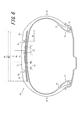
第3の実施形態における空気入りタイヤ101(図6参照)では、トレッド部11、サイドウォール部12、ビード部13、カーカス15、および傾斜ベルト16の構成ならびに周方向主溝14の配設位置は、第1の実施形態と同じである。
したがって、第1の実施形態と同様に、タイヤのスリップアングルが変化する様々な走行条件下において、確実にコーナリングパワーが向上し、高い旋回性が得られる。In the pneumatic tire 101 (see FIG. 6) according to the third embodiment, the configuration of the
Therefore, as in the first embodiment, the cornering power is reliably improved and high turning performance can be obtained under various traveling conditions in which the tire slip angle changes.
空気入りタイヤ101では、周方向ベルト171は、周方向ベルト層として、タイヤ幅方向に分割された第1の周方向ベルト層171cおよび第2の周方向ベルト層171dを有する。第1の周方向ベルト層171cおよび第2の周方向ベルト層171dが中央領域Cにおいて重ねられることにより、高剛性領域が形成される。中央領域Cに配設される周方向ベルト層は2層である一方で、中央領域Cのタイヤ幅方向外側の領域で配設される周方向ベルト層は1層なので、中央領域Cではタイヤ幅方向外側の領域よりも単位幅あたりのタイヤ周方向剛性が高い。また、第2の実施形態と同様に、中央領域Cのタイヤ幅方向幅W4は、周方向ベルト171のタイヤ幅方向幅をW3とすると、好ましくは、0.2W3以上0.6W3以下である。
したがって、第2の実施形態と同様に、高剛性領域を形成することにより騒音性能を向上可能である。
また、周方向ベルト層の層数を、中央領域Cにおいて2層とし、中央領域Cのタイヤ幅方向外側の領域において1層として高剛性領域を形成することにより、騒音性能を維持しながら、製造コストおよびタイヤ重量の増加を抑制可能である。In the
Therefore, as in the second embodiment, noise performance can be improved by forming a highly rigid region.
In addition, the number of circumferential belt layers is two in the central region C, and a high rigidity region is formed as one layer in the region outside the central region C in the tire width direction. Increase in cost and tire weight can be suppressed.
次に、本発明の第4の実施形態を説明する。第4の実施形態では周方向ベルトの構成が第1の実施形態と異なっている。以下に、第1の実施形態と異なる点を中心に第4の実施形態について説明する。なお、第1から3の実施形態と同じ構成を有する部位には同じ符号を付す。 Next, a fourth embodiment of the present invention will be described. In the fourth embodiment, the configuration of the circumferential belt is different from that of the first embodiment. The fourth embodiment will be described below with a focus on differences from the first embodiment. In addition, the same code | symbol is attached | subjected to the site | part which has the same structure as 1st-3rd embodiment.
第4の実施形態における空気入りタイヤ102(図7参照)では、トレッド部11、サイドウォール部12、ビード部13、カーカス15、傾斜ベルト16の構成ならびに周方向主溝14の配設位置は、第1の実施形態と同じである。
したがって、第1の実施形態と同様に、タイヤのスリップアングルが変化する様々な走行条件下において、コーナリングパワーが向上し、高い旋回性が得られる。In the pneumatic tire 102 (see FIG. 7) according to the fourth embodiment, the configuration of the
Therefore, similarly to the first embodiment, cornering power is improved and high turning performance is obtained under various traveling conditions in which the tire slip angle changes.
空気入りタイヤ102では、周方向ベルト172は、周方向ベルト層として、1層の周方向ベルト層を有する。この周方向ベルト層では、中央領域Cにおいて、中央領域Cよりタイヤ幅方向外側の領域のコードより高い剛性のコードを設けることにより、高剛性領域が形成される。コードのヤング率および打ち込み本数の少なくとも一方を局所的に増加させることにより、中央領域における周方向剛性を増加可能である。なお、ヤング率はコードの材質の変更、撚り構造の変更などにより調整可能である。このような構成により、中央領域Cにおいては、中央領域Cよりもタイヤ幅方向外側の領域よりもタイヤ周方向の剛性が増大する。第2の実施形態と同様に、中央領域Cのタイヤ幅方向幅W4は、周方向ベルト171のタイヤ幅方向幅をW3とすると、好ましくは、0.2W3以上0.6W3以下である。
したがって、第2の実施形態と同様に、高剛性領域を形成することにより騒音性能を向上可能である。In the
Therefore, as in the second embodiment, noise performance can be improved by forming a highly rigid region.
次に、本発明の第5の実施形態を説明する。第5の実施形態では傾斜ベルトの構成が第1の実施形態と異なっている。以下に、第1の実施形態と異なる点を中心に第5の実施形態について説明する。なお、第1から4の実施形態と同じ構成を有する部位には同じ符号を付す。 Next, a fifth embodiment of the present invention will be described. In the fifth embodiment, the configuration of the inclined belt is different from that of the first embodiment. The fifth embodiment will be described below with a focus on differences from the first embodiment. In addition, the same code | symbol is attached | subjected to the site | part which has the same structure as 1st-4th embodiment.
第5の実施形態における空気入りタイヤ103(図8参照)では、トレッド部11、サイドウォール部12、ビード部13、カーカス15、周方向ベルト17の構成ならびに周方向主溝14の配設位置は、第1の実施形態と同じである。 In the pneumatic tire 103 (see FIG. 8) in the fifth embodiment, the configuration of the
空気入りタイヤ103では、傾斜ベルト163は、傾斜ベルト層として、少なくとも1層の高角度傾斜ベルト層163cおよび少なくとも1層の低角度傾斜ベルト層163dからなる。好ましくは、傾斜ベルト層は1層の高角度傾斜ベルト層および1層の低角度傾斜ベルト層のみによって構成される。
傾斜ベルト層が1層の高角度傾斜ベルト層および1層の低角度傾斜ベルト層のみによって構成されることにより、騒音性能を維持しながら、製造コストおよびタイヤ重量の増加を抑制可能である。In the
By constituting the inclined belt layer by only one high-angle inclined belt layer and one low-angle inclined belt layer, it is possible to suppress an increase in manufacturing cost and tire weight while maintaining noise performance.
本実施形態においては、低角度傾斜ベルト層163dが高角度傾斜ベルト層163cよりタイヤ径方向外側に設けられている。あるいは、低角度傾斜ベルト層163dが高角度傾斜ベルト層163cよりタイヤ径方向内側に設けられていてもよい。 In the present embodiment, the low-angle
高角度傾斜ベルト層163cのコードのタイヤ周方向に対する傾斜角度は、35°以上90°以下である。さらに好ましくは、高角度傾斜ベルト層163cのコードのタイヤ周方向に対する傾斜角度は50°以上である。高角度傾斜ベルト層163cでは、第1の実施形態における第1の高角度傾斜ベルト層16aと同様に、タイヤ幅方向端縁は、タイヤ赤道CLを境とするトレッド半部において、タイヤ幅方向最も外側に配置された周方向主溝14よりも、タイヤ幅方向外側に位置している。また、第1の実施形態における第1の高角度傾斜ベルト層16aと同様に、高角度傾斜ベルト層163cのタイヤ幅方向端縁からタイヤ幅方向の最も外側に配置された周方向主溝14の中心までのタイヤ幅方向間隔W 5が、高角度傾斜ベルト層163cのタイヤ幅方向幅をW1として、0.2W1以上0.35W1以下である。
したがって、第1の実施形態と同様に、タイヤのスリップアングルが変化する様々な走行条件下において、コーナリングパワーが増大し、高い旋回性が得られる。 The inclination angle of the cord of the high-angle
Therefore, as in the first embodiment, cornering power is increased and high turning performance is obtained under various traveling conditions in which the tire slip angle changes.
低角度傾斜ベルト層163dのコードのタイヤ周方向に対する傾斜角度は、高角度傾斜ベルト層163cのコードの傾斜角度よりも小さく、且つ30°以下である。低角度傾斜ベルト層163dのコードは、高角度傾斜ベルト層163cのコードに対してタイヤ赤道CLを挟んで交差している。
低角度傾斜ベルト層163dを設けることにより、騒音性能を向上可能である。当該作用について、以下に説明する。
前述のように、高角度傾斜ベルト層163cのコードのタイヤ周方向に対する傾斜角度が大きなタイヤは、400Hzから2kHzの高周波域において、断面方向の1次、2次および3次などの振動モードにてトレッド面が一律に大きく振動する形状(図5、2点鎖線参照)となるため、大きな放射音が生じる。そこで、低角度傾斜ベルト層163dにおけるコードのタイヤ周方向に対する傾斜角度が、高角度傾斜ベルト層163cのコードの傾斜角度より小さく且つ30°以下であることにより、タイヤ赤道CL付近における、タイヤ周方向の面外曲げ剛性が適度に保持される。その結果、トレッド面のタイヤ径方向への広がりが抑制され(図5、破線参照)、放射音が低減化される。The inclination angle of the cord of the low-angle
The noise performance can be improved by providing the low-angle
As described above, a tire having a large inclination angle with respect to the tire circumferential direction of the cord of the high-angle
また、好ましくは、低角度傾斜ベルト層163dのコードのタイヤ周方向に対する傾斜角度は10°以上である。
低角度傾斜ベルト層163dのコードのタイヤ周方向に対する傾斜角度が10°以上であることにより、高角度傾斜ベルト層163cによる接地長を確保する作用を阻害すること無く、タイヤ周方向の面外曲げ剛性を確保可能である。Preferably, the inclination angle of the cord of the low-angle
When the inclination angle of the cord of the low-angle
また、好ましくは、低角度傾斜ベルト層163dのタイヤ幅方向幅W2は、高角度傾斜ベルト層163cのタイヤ幅方向幅をW1として0.6W1以下である。
低角度傾斜ベルト層163dのタイヤ幅方向幅W2が0.6W1以下であることにより、騒音性能を向上可能であり、コーナリングパワーの向上効果を維持可能であり、また転がり抵抗を低減可能である。当該作用について、以下に説明する。
タイヤ周方向の面外曲げ剛性が大きい領域のタイヤ幅方向幅が大きくなり過ぎると、トレッド部11が一律に振動し易くなるため、放射音の低減化効果が低下する。そこで、低角度傾斜ベルト層163dのタイヤ幅方向幅W2が0.6W1以下であることにより、トレッド部11全体が振動するモードの誘発を抑制するので、騒音性能を向上可能である。
さらに、車両の旋回時においては、トレッド部11の踏面が路面に強く押付けられることによりコーナリングパワーが得られる。それゆえ、タイヤ周方向の剛性に対してタイヤに負荷される荷重が不十分である場合、トレッド部11の踏面の路面への押し付けが不十分となる。その結果、トレッド部11のショルダー域が路面から浮き上がる現象が生じ得、コーナリングパワーの向上効果が低下する。そこで、低角度傾斜ベルト層163dのタイヤ幅方向幅W2が0.6W1以下であることにより、トレッド部11のショルダー域におけるタイヤ周方向の剛性が適度に低減化し、トレッド部11の浮き上がりの発生を抑制できる。その結果、コーナリングパワーの向上効果が維持される。
さらに、低角度傾斜ベルト層163dのタイヤ幅方向幅W2が0.6W1以下であることにより、タイヤ重量が軽量化されるので、空気入りタイヤ103の転がり抵抗を低減化可能である。Preferably, the width W 2 in the tire width direction of the low-angle
When the width W 2 in the tire width direction of the low-angle
If the width in the tire width direction of the region where the out-of-plane bending rigidity in the tire circumferential direction is large becomes too large, the
Further, when the vehicle is turning, cornering power is obtained by strongly pressing the
Furthermore, since the tire weight is reduced when the width W 2 in the tire width direction of the low-angle
また、好ましくは、低角度傾斜ベルト層163dのタイヤ幅方向幅W2は、0.25W1以上である。
このような構成によれば、タイヤ赤道CL付近におけるベルト剛性が十分に確保されるため、トレッド部11のタイヤ周方向への広がりを抑制して放射音を低減化させるとともに、コーナリングパワーを確実に増大可能である。Preferably, the width W 2 in the tire width direction of the low-angle
According to such a configuration, the belt rigidity in the vicinity of the tire equator CL is sufficiently ensured, so that the spread of the
次に本発明に従うタイヤおよび比較例のタイヤについて、コーナリングパワー、騒音性能、転がり抵抗に関する評価を行ったので、以下に説明する。評価においては、比較例1から4と、実施例1から4とを比較した。 Next, the tire according to the present invention and the tire of the comparative example were evaluated for cornering power, noise performance, and rolling resistance, and will be described below. In evaluation, Comparative Examples 1 to 4 and Examples 1 to 4 were compared.
比較例1〜3は、第1の実施形態の空気入りタイヤ(図1参照)に似た構成を有している。ただし、比較例1では、傾斜ベルト層のコードのタイヤ周方向に対する傾斜角度が小さく、且つ広幅傾斜ベルト層(第1の実施形態における第1の高角度傾斜ベルト層)の端縁から周方向主溝までの間隔が広幅傾斜ベルト層のタイヤ幅方向幅の0.2倍未満である点において第1の実施形態の空気入りタイヤの構成と異なる。比較例2では、広幅傾斜ベルト層の端縁から周方向主溝までの間隔が広幅傾斜ベルト層のタイヤ幅方向幅の0.2倍未満である点において第1の実施形態の空気入りタイヤの構成と異なる。比較例3では、広幅傾斜ベルト層の端縁から周方向主溝までの間隔が広幅傾斜ベルト層のタイヤ幅方向幅の0.35倍を越える点において第1の実施形態の空気入りタイヤの構成と異なる。
実施例1は第1の実施形態の空気入りタイヤ(図1参照)に対応する。実施例2は第2の実施形態の空気入りタイヤ(図4参照)に対応する。実施例3は第3の実施形態の空気入りタイヤ(図6参照)に対応する。実施例4は第5の実施形態の空気入りタイヤ(図8参照)に対応する。実施例5は、第5の実施形態の空気入りタイヤ(図8参照)に似た構成を有している。ただし、実施例5では、狭幅傾斜ベルト層(第5の実施形態における低角度傾斜ベルト層)のタイヤ幅方向幅が広幅傾斜ベルト層(第5の実施形態における高角度傾斜ベルト層)のタイヤ幅方向幅の0.6倍を超える点において第5の実施形態の空気入りタイヤの構成と異なる。
比較例1から3および実施例1から5の空気入りタイヤの諸元を表1に示す。Comparative Examples 1 to 3 have a configuration similar to the pneumatic tire (see FIG. 1) of the first embodiment. However, in Comparative Example 1, the inclination angle of the cord of the inclined belt layer with respect to the tire circumferential direction is small, and the circumferential main line extends from the edge of the wide inclined belt layer (the first high-angle inclined belt layer in the first embodiment). It differs from the configuration of the pneumatic tire of the first embodiment in that the distance to the groove is less than 0.2 times the width in the tire width direction of the wide inclined belt layer. In Comparative Example 2, the pneumatic tire of the first embodiment is different in that the distance from the edge of the wide inclined belt layer to the circumferential main groove is less than 0.2 times the width in the tire width direction of the wide inclined belt layer. Different from the configuration. In Comparative Example 3, the configuration of the pneumatic tire of the first embodiment in that the distance from the edge of the wide inclined belt layer to the circumferential main groove exceeds 0.35 times the width in the tire width direction of the wide inclined belt layer. And different.
Example 1 corresponds to the pneumatic tire of the first embodiment (see FIG. 1). Example 2 corresponds to the pneumatic tire of the second embodiment (see FIG. 4). Example 3 corresponds to the pneumatic tire of the third embodiment (see FIG. 6). Example 4 corresponds to the pneumatic tire of the fifth embodiment (see FIG. 8). Example 5 has a configuration similar to the pneumatic tire of the fifth embodiment (see FIG. 8). However, in Example 5, the tire in which the width in the tire width direction of the narrow inclined belt layer (low angle inclined belt layer in the fifth embodiment) is a wide inclined belt layer (high angle inclined belt layer in the fifth embodiment) is used. It differs from the configuration of the pneumatic tire of the fifth embodiment in that it exceeds 0.6 times the width in the width direction.
Table 1 shows the specifications of the pneumatic tires of Comparative Examples 1 to 3 and Examples 1 to 5.

表1において、
※1は、タイヤ周方向に対するコードの傾斜角度である。
※2は、ヤング率、層数、および打ち込み本数の積であるパラメータXである。
※3は、タイヤ幅方向の最も外側に配置された周方向主溝の位置を、広幅傾斜ベルト層のタイヤ幅方向端縁から当該周方向主溝のタイヤ幅方向中心までのタイヤ幅方向間隔として表わしたものである。In Table 1,
* 1 is the inclination angle of the cord with respect to the tire circumferential direction.
* 2 is a parameter X that is a product of Young's modulus, the number of layers, and the number of driving.
* 3: The position of the circumferential main groove arranged on the outermost side in the tire width direction is the distance in the tire width direction from the tire width direction edge of the wide inclined belt layer to the center of the circumferential main groove in the tire width direction. It is a representation.
<コーナリングパワー評価試験>
表1に示した諸元の、比較例1から3および実施例1から5のタイヤを試作し、適用リムに組付け、車両に装着し、フラットベルト式コーナリング試験機において測定を行った。ベルト速度を100km/hとして、タイヤの転動方向ドラムの円周方向との間のスリップアングル(SA)を1°、3°の状態でコーナリングフォースを測定した。結果を表2に示す。
結果は、比較例1のコーナリングフォースを100として指数化したものである。当該指数が大きくなる程、各スリップアングルにおけるコーナリングフォース、すなわち各スリップアングルにおけるコーナリングパワーが良好であることを示す。<Cornering power evaluation test>
Tires of Comparative Examples 1 to 3 and Examples 1 to 5 having the specifications shown in Table 1 were made as trial products, assembled to the applicable rim, mounted on a vehicle, and measured with a flat belt cornering tester. The cornering force was measured with a belt speed of 100 km / h and a slip angle (SA) between the circumferential direction of the rolling direction drum of the tire being 1 ° and 3 °. The results are shown in Table 2.
The results are obtained by indexing the cornering force of Comparative Example 1 as 100. The larger the index, the better the cornering force at each slip angle, that is, the cornering power at each slip angle.
<騒音性能評価試験>
表1に示した諸元の、比較例1から3および実施例1から5のタイヤを試作し、適用リムに組付け、車両に装着し、走行試験用ドラム上で、当該ドラムを100km/hの速度で回転させるとともに、マイク移動式でノイズレベルを測定した。結果を表2に示す。
結果は、比較例1のノイズレベルを基準としたノイズレベルの差を評価した。数値が低いほど、騒音の低減効果が良好であることを示す。<Noise performance evaluation test>
The tires of Comparative Examples 1 to 3 and Examples 1 to 5 having the specifications shown in Table 1 are made as trial products, assembled to the applicable rim, mounted on the vehicle, and the drum is set to 100 km / h on the running test drum. The noise level was measured with a microphone moving type. The results are shown in Table 2.
As a result, the difference in noise level with respect to the noise level of Comparative Example 1 was evaluated. The lower the value, the better the noise reduction effect.
<転がり抵抗評価試験>
表1に示した諸元の、比較例1から3および実施例1から5のタイヤを試作し、適用リムに組付け、車両に装着し、走行試験用ドラム上で、当該ドラムを100km/hの速度で回転させて転がり抵抗を測定し、転がり抵抗係数(RRC)を算出した。結果を表2に示す。
結果は、比較例1の転がり抵抗係数の逆数を指数化したものである。数値が高いほど、転がり抵抗が良好であることを示す。<Rolling resistance evaluation test>
The tires of Comparative Examples 1 to 3 and Examples 1 to 5 having the specifications shown in Table 1 are made as trial products, assembled to the applicable rim, mounted on the vehicle, and the drum is set to 100 km / h on the running test drum. The rolling resistance was measured by rotating at a speed of 5 to calculate the rolling resistance coefficient (RRC). The results are shown in Table 2.
The result is an index of the reciprocal of the rolling resistance coefficient of Comparative Example 1. It shows that rolling resistance is so favorable that a numerical value is high.
<コーナリングパワー評価結果>
表2のコーナリングフォースの行に示すように、実施例1から5と比較例2、3とを比べると、スリップアングルが1°のときも3°のときも、比較例1に比べてコーナリングフォースが向上している。したがって、タイヤ周方向に対する傾斜角度が35°以上90°未満であって、0.2W1≦W5≦0.35W1であれば、スリップアングルが1°または3°においてもコーナリングパワーが向上することが分かる。<Cornering power evaluation results>
As shown in the row of cornering force in Table 2, when Examples 1 to 5 are compared with Comparative Examples 2 and 3, the cornering force is compared to Comparative Example 1 when the slip angle is 1 ° or 3 °. Has improved. Therefore, it is less than the inclination angle of 35 ° or more 90 ° to the tire circumferential direction, if 0.2W 1 ≦ W 5 ≦ 0.35W 1 , the slip angle is also improved cornering power at 1 ° or 3 ° I understand that.
<騒音評価結果>
表2の騒音性能の行に示すように、実施例1と実施例2、3とを比べると、実施例2、3の方が実施例1よりも騒音性能が良好である。したがって、周方向ベルトによって高剛性領域を形成することにより、騒音性能が向上することが分かる。また、実施例1と実施例4とを比べると、実施例4の方が実施例1よりも騒音性能が良好である。したがって、コードのタイヤ周方向に対する傾斜角度が高角度傾斜ベルト層のコードの傾斜角度より小さく且つ30°以下である低角度傾斜ベルト層を設けることにより、騒音性能が向上することが分かる。<Noise evaluation results>
As shown in the row of noise performance in Table 2, when Example 1 and Examples 2 and 3 are compared, Examples 2 and 3 have better noise performance than Example 1. Therefore, it can be seen that the noise performance is improved by forming the high rigidity region by the circumferential belt. Further, comparing Example 1 and Example 4, Example 4 has better noise performance than Example 1. Therefore, it can be seen that the noise performance is improved by providing the low-angle inclined belt layer in which the inclination angle of the cord with respect to the tire circumferential direction is smaller than the inclination angle of the cord of the high-angle inclined belt layer and 30 ° or less.
<転がり抵抗評価結果>
表2のRRCの行に示すように、実施例5と実施例4とを比べると、実施例4の方が実施例5よりも転がり抵抗性能が良好である。したがって、W2≦0.6W1であれば、転がり抵抗性能が向上することが分かる。<Rolling resistance evaluation results>
As shown in the RRC row of Table 2, when Example 5 and Example 4 are compared, Example 4 has better rolling resistance performance than Example 5. Therefore, it can be seen that rolling resistance performance is improved when W 2 ≦ 0.6W 1 .
10、100、101、102、103:空気入りタイヤ 11:トレッド部 12:サイドウォール部 13:ビード部 14:周方向主溝 15:カーカス 16、163:傾斜ベルト 16a:第1の高角度傾斜ベルト層 16b:第2の高角度傾斜ベルト層
163c:高角度傾斜ベルト層 163d:低角度傾斜ベルト層 17、170、171、172:周方向ベルト 170a:広幅の周方向ベルト層 170b:狭幅の周方向ベルト層 171c:第1の周方向ベルト層 171d:第2の周方向ベルト層 18:ショルダー陸部 C:中央領域 CL:タイヤ赤道 R:適用リム10, 100, 101, 102, 103: Pneumatic tire 11: Tread portion 12: Side wall portion 13: Bead portion 14: Circumferential main groove 15:
Claims (9)
前記トレッド部踏面には、タイヤ周方向に沿って延びる少なくとも1本の周方向主溝が設けられ、
前記傾斜ベルトは、前記少なくとも2層の傾斜ベルト層として、前記コードのタイヤ周方向に対する傾斜角度が35°以上90°以下である高角度傾斜ベルト層を含み、
少なくとも一方のトレッド半部において、最もタイヤ幅方向外側に配置された周方向主溝よりも前記高角度傾斜ベルト層のタイヤ幅方向端縁がタイヤ幅方向外側に位置し、該端縁から該周方向主溝の中心までのタイヤ幅方向間隔が、前記高角度傾斜ベルト層のタイヤ幅方向幅をW1として、0.2W1以上0.35W 1 以下であり、
前記高角度傾斜ベルト層として、第1の高角度傾斜ベルト層と、前記第1の高角度傾斜ベルト層よりもタイヤ径方向外側に配置された第2の高角度傾斜ベルト層と、が設けられており、
前記第2の高角度傾斜ベルト層のコードは、タイヤ赤道に対して、前記第1の高角度傾斜ベルト層のコードと同じ方向に傾斜している
ことを特徴とする空気入りタイヤ。 A carcass that includes a pair of bead portions and a tread portion, and is disposed on the outer side in the tire radial direction of the crown portion of the carcass and inclined with respect to the tire circumferential direction And an inclined belt composed of at least two inclined belt layers, and at least one circumferential belt layer having a cord disposed on the outer side in the tire radial direction of the crown portion of the carcass and extending along the tire circumferential direction. A pneumatic tire comprising a circumferential belt,
The tread portion tread is provided with at least one circumferential main groove extending along the tire circumferential direction,
The inclined belt includes, as the at least two inclined belt layers, a high-angle inclined belt layer in which an inclination angle of the cord with respect to a tire circumferential direction is not less than 35 ° and not more than 90 °,
In at least one half of the tread, an edge in the tire width direction of the high-angle inclined belt layer is located on the outer side in the tire width direction from the circumferential main groove arranged on the outermost side in the tire width direction. tire width direction distance to the center of the direction main grooves, the tire width direction width of the high-angle inclined belt layer as W 1, and at 0.2 W 1 or 0.35 W 1 or less,
As the high-angle inclined belt layer, a first high-angle inclined belt layer and a second high-angle inclined belt layer disposed on the outer side in the tire radial direction than the first high-angle inclined belt layer are provided. And
The cord of the second high-angle inclined belt layer is inclined in the same direction as the cord of the first high-angle inclined belt layer with respect to the tire equator .
前記低角度傾斜ベルト層のタイヤ幅方向幅W 2 が、0.6W1以下である、請求項1に記載の空気入りタイヤ。 The inclined belt is a low-angle inclined belt layer in which the inclination angle of the cord with respect to the tire circumferential direction is smaller than that of the high-angle inclined belt layer and 30 ° or less as the at least two inclined belt layers, Including
The low angle inclined belt layer tire width direction width W 2 of, at 0.6 W 1 or less, pneumatic tire according to claim 1.
前記狭幅の周方向ベルト層は、前記広幅の周方向ベルト層よりもタイヤ径方向外側に配置されている、請求項1〜5のいずれか1項に記載の空気入りタイヤ。The pneumatic tire according to any one of claims 1 to 5, wherein the narrow circumferential belt layer is disposed more radially outward than the wide circumferential belt layer.
前記第1の周方向ベルト層および前記第2の周方向ベルト層が、前記中央領域において、タイヤ径方向に重ねられている、請求項2又は3に記載の空気入りタイヤ。The pneumatic tire according to claim 2 or 3, wherein the first circumferential belt layer and the second circumferential belt layer are overlapped in the tire radial direction in the central region.
Applications Claiming Priority (3)
| Application Number | Priority Date | Filing Date | Title |
|---|---|---|---|
| JP2013224539 | 2013-10-29 | ||
| JP2013224539 | 2013-10-29 | ||
| PCT/JP2014/003510 WO2015063974A1 (en) | 2013-10-29 | 2014-07-01 | Pneumatic tire |
Publications (2)
| Publication Number | Publication Date |
|---|---|
| JPWO2015063974A1 JPWO2015063974A1 (en) | 2017-03-09 |
| JP6450320B2 true JP6450320B2 (en) | 2019-01-09 |
Family
ID=53003612
Family Applications (1)
| Application Number | Title | Priority Date | Filing Date |
|---|---|---|---|
| JP2015544762A Expired - Fee Related JP6450320B2 (en) | 2013-10-29 | 2014-07-01 | Pneumatic tire |
Country Status (5)
| Country | Link |
|---|---|
| US (1) | US10179481B2 (en) |
| EP (1) | EP3064373B1 (en) |
| JP (1) | JP6450320B2 (en) |
| CN (1) | CN105682941B (en) |
| WO (1) | WO2015063974A1 (en) |
Families Citing this family (7)
| Publication number | Priority date | Publication date | Assignee | Title |
|---|---|---|---|---|
| JP6450321B2 (en) * | 2013-10-29 | 2019-01-09 | 株式会社ブリヂストン | tire |
| JP6393690B2 (en) * | 2013-10-29 | 2018-09-19 | 株式会社ブリヂストン | tire |
| JP6907552B2 (en) * | 2017-01-20 | 2021-07-21 | 横浜ゴム株式会社 | Pneumatic tires |
| WO2019048762A1 (en) * | 2017-09-06 | 2019-03-14 | Compagnie Generale Des Etablissements Michelin | Lightweight tyre |
| JP6720997B2 (en) * | 2018-04-10 | 2020-07-08 | 横浜ゴム株式会社 | Run flat tires |
| CN108515813A (en) * | 2018-04-16 | 2018-09-11 | 中策橡胶集团有限公司 | A kind of low flat pneumatic radial tire of load-carrying |
| CN109835123B (en) * | 2019-01-29 | 2021-09-03 | 安徽佳通乘用子午线轮胎有限公司 | Pneumatic tire capable of reducing rolling resistance |
Family Cites Families (17)
| Publication number | Priority date | Publication date | Assignee | Title |
|---|---|---|---|---|
| JPS52111104A (en) * | 1976-03-15 | 1977-09-17 | Bridgestone Corp | Pneumatic tire for heavy vehicle |
| JPH02286404A (en) * | 1989-04-26 | 1990-11-26 | Toyo Tire & Rubber Co Ltd | Radial tire |
| JP3059539B2 (en) * | 1991-09-05 | 2000-07-04 | 株式会社ブリヂストン | High performance pneumatic radial tire |
| JP2001301421A (en) * | 2000-04-21 | 2001-10-31 | Bridgestone Corp | Pneumatic tire |
| JP4540487B2 (en) * | 2005-01-13 | 2010-09-08 | 株式会社ブリヂストン | Pneumatic tire |
| EP1852276B1 (en) | 2005-01-13 | 2010-08-11 | Bridgestone Corporation | Pneumatic tire |
| US7575031B2 (en) * | 2005-11-22 | 2009-08-18 | Sumitomo Rubber Industries, Ltd. | Heavy duty radial tire with belt reinforcing rubber layer having axially inner and outer rubber portions |
| JP5164453B2 (en) * | 2007-07-03 | 2013-03-21 | 株式会社ブリヂストン | Pneumatic tire |
| JP2012020673A (en) * | 2010-07-15 | 2012-02-02 | Bridgestone Corp | Pneumatic tire |
| JP2011016338A (en) * | 2009-07-10 | 2011-01-27 | Sumitomo Rubber Ind Ltd | Method for producing radial tire for heavy load |
| EP2463119B1 (en) * | 2009-08-05 | 2017-05-03 | Bridgestone Corporation | Pneumatic tire |
| CN103068594B (en) | 2010-06-21 | 2015-11-25 | 株式会社普利司通 | Pneumatic radial tire for car |
| CN103298631B (en) | 2010-11-15 | 2016-03-16 | 株式会社普利司通 | Pneumatic radial tire for car |
| JP2012171423A (en) * | 2011-02-18 | 2012-09-10 | Bridgestone Corp | Pneumatic radial tire |
| WO2013042256A1 (en) | 2011-09-22 | 2013-03-28 | 横浜ゴム株式会社 | Pneumatic tire |
| JP5993863B2 (en) | 2011-11-02 | 2016-09-14 | 株式会社ブリヂストン | Pneumatic radial tire for passenger cars |
| JP5620537B2 (en) * | 2013-04-03 | 2014-11-05 | 株式会社ブリヂストン | Pneumatic tire |
-
2014
- 2014-07-01 US US15/029,333 patent/US10179481B2/en active Active
- 2014-07-01 CN CN201480059168.8A patent/CN105682941B/en active Active
- 2014-07-01 EP EP14857635.8A patent/EP3064373B1/en active Active
- 2014-07-01 WO PCT/JP2014/003510 patent/WO2015063974A1/en active Application Filing
- 2014-07-01 JP JP2015544762A patent/JP6450320B2/en not_active Expired - Fee Related
Also Published As
| Publication number | Publication date |
|---|---|
| CN105682941B (en) | 2018-10-12 |
| US20160272007A1 (en) | 2016-09-22 |
| CN105682941A (en) | 2016-06-15 |
| JPWO2015063974A1 (en) | 2017-03-09 |
| EP3064373A4 (en) | 2016-11-09 |
| EP3064373A1 (en) | 2016-09-07 |
| EP3064373B1 (en) | 2019-04-10 |
| WO2015063974A1 (en) | 2015-05-07 |
| US10179481B2 (en) | 2019-01-15 |
Similar Documents
| Publication | Publication Date | Title |
|---|---|---|
| JP6450320B2 (en) | Pneumatic tire | |
| JP4570526B2 (en) | Heavy duty pneumatic tire | |
| JP6175427B2 (en) | Pneumatic tire | |
| JP6393690B2 (en) | tire | |
| JP5525073B1 (en) | Heavy duty tire | |
| JP6450321B2 (en) | tire | |
| JP5628946B2 (en) | Heavy duty tire | |
| JP4555873B2 (en) | Heavy duty tire | |
| JP6450111B2 (en) | Pneumatic tire | |
| JP6555998B2 (en) | Pneumatic tire | |
| JP6129724B2 (en) | Pneumatic tire | |
| JP6245003B2 (en) | Pneumatic tire | |
| JP6294792B2 (en) | Pneumatic tire | |
| CN108463358B (en) | Pneumatic tire | |
| JP2011245938A (en) | Pneumatic tire | |
| JP5405992B2 (en) | Heavy duty pneumatic radial tire | |
| JP5331535B2 (en) | Heavy duty pneumatic radial tire | |
| JP2014168976A (en) | Pneumatic tire | |
| JP6517612B2 (en) | Pneumatic tire | |
| JP6294791B2 (en) | Pneumatic tire | |
| JP6129691B2 (en) | Pneumatic tire | |
| JP2015037943A (en) | Pneumatic tire | |
| JP6362967B2 (en) | Pneumatic tire | |
| JP6185610B2 (en) | tire | |
| WO2017204353A1 (en) | Heavy load tire |
Legal Events
| Date | Code | Title | Description |
|---|---|---|---|
| A621 | Written request for application examination |
Free format text: JAPANESE INTERMEDIATE CODE: A621 Effective date: 20170623 |
|
| A131 | Notification of reasons for refusal |
Free format text: JAPANESE INTERMEDIATE CODE: A131 Effective date: 20180821 |
|
| A521 | Request for written amendment filed |
Free format text: JAPANESE INTERMEDIATE CODE: A523 Effective date: 20181005 |
|
| TRDD | Decision of grant or rejection written | ||
| A01 | Written decision to grant a patent or to grant a registration (utility model) |
Free format text: JAPANESE INTERMEDIATE CODE: A01 Effective date: 20181113 |
|
| A61 | First payment of annual fees (during grant procedure) |
Free format text: JAPANESE INTERMEDIATE CODE: A61 Effective date: 20181207 |
|
| R150 | Certificate of patent or registration of utility model |
Ref document number: 6450320 Country of ref document: JP Free format text: JAPANESE INTERMEDIATE CODE: R150 |
|
| R250 | Receipt of annual fees |
Free format text: JAPANESE INTERMEDIATE CODE: R250 |
|
| LAPS | Cancellation because of no payment of annual fees |