US10207542B2 - Pneumatic radial tire for passenger vehicle - Google Patents
Pneumatic radial tire for passenger vehicle Download PDFInfo
- Publication number
- US10207542B2 US10207542B2 US14/355,597 US201214355597A US10207542B2 US 10207542 B2 US10207542 B2 US 10207542B2 US 201214355597 A US201214355597 A US 201214355597A US 10207542 B2 US10207542 B2 US 10207542B2
- Authority
- US
- United States
- Prior art keywords
- tire
- width
- belt
- reinforcing layer
- region
- Prior art date
- Legal status (The legal status is an assumption and is not a legal conclusion. Google has not performed a legal analysis and makes no representation as to the accuracy of the status listed.)
- Expired - Fee Related
Links
Images


Classifications
-
- B—PERFORMING OPERATIONS; TRANSPORTING
- B60—VEHICLES IN GENERAL
- B60C—VEHICLE TYRES; TYRE INFLATION; TYRE CHANGING; CONNECTING VALVES TO INFLATABLE ELASTIC BODIES IN GENERAL; DEVICES OR ARRANGEMENTS RELATED TO TYRES
- B60C3/00—Tyres characterised by the transverse section
- B60C3/04—Tyres characterised by the transverse section characterised by the relative dimensions of the section, e.g. low profile
-
- B—PERFORMING OPERATIONS; TRANSPORTING
- B60—VEHICLES IN GENERAL
- B60C—VEHICLE TYRES; TYRE INFLATION; TYRE CHANGING; CONNECTING VALVES TO INFLATABLE ELASTIC BODIES IN GENERAL; DEVICES OR ARRANGEMENTS RELATED TO TYRES
- B60C9/00—Reinforcements or ply arrangement of pneumatic tyres
- B60C9/18—Structure or arrangement of belts or breakers, crown-reinforcing or cushioning layers
- B60C9/20—Structure or arrangement of belts or breakers, crown-reinforcing or cushioning layers built-up from rubberised plies each having all cords arranged substantially parallel
- B60C9/22—Structure or arrangement of belts or breakers, crown-reinforcing or cushioning layers built-up from rubberised plies each having all cords arranged substantially parallel the plies being arranged with all cords disposed along the circumference of the tyre
- B60C2009/2223—Structure or arrangement of belts or breakers, crown-reinforcing or cushioning layers built-up from rubberised plies each having all cords arranged substantially parallel the plies being arranged with all cords disposed along the circumference of the tyre with an interrupted zero degree ply, e.g. using two or more portions for the same ply
-
- B—PERFORMING OPERATIONS; TRANSPORTING
- B60—VEHICLES IN GENERAL
- B60C—VEHICLE TYRES; TYRE INFLATION; TYRE CHANGING; CONNECTING VALVES TO INFLATABLE ELASTIC BODIES IN GENERAL; DEVICES OR ARRANGEMENTS RELATED TO TYRES
- B60C9/00—Reinforcements or ply arrangement of pneumatic tyres
- B60C9/18—Structure or arrangement of belts or breakers, crown-reinforcing or cushioning layers
- B60C9/20—Structure or arrangement of belts or breakers, crown-reinforcing or cushioning layers built-up from rubberised plies each having all cords arranged substantially parallel
- B60C9/22—Structure or arrangement of belts or breakers, crown-reinforcing or cushioning layers built-up from rubberised plies each having all cords arranged substantially parallel the plies being arranged with all cords disposed along the circumference of the tyre
- B60C2009/2228—Structure or arrangement of belts or breakers, crown-reinforcing or cushioning layers built-up from rubberised plies each having all cords arranged substantially parallel the plies being arranged with all cords disposed along the circumference of the tyre characterised by special physical properties of the zero degree plies
- B60C2009/2233—Modulus of the zero degree ply
-
- B—PERFORMING OPERATIONS; TRANSPORTING
- B60—VEHICLES IN GENERAL
- B60C—VEHICLE TYRES; TYRE INFLATION; TYRE CHANGING; CONNECTING VALVES TO INFLATABLE ELASTIC BODIES IN GENERAL; DEVICES OR ARRANGEMENTS RELATED TO TYRES
- B60C9/00—Reinforcements or ply arrangement of pneumatic tyres
- B60C9/18—Structure or arrangement of belts or breakers, crown-reinforcing or cushioning layers
- B60C9/20—Structure or arrangement of belts or breakers, crown-reinforcing or cushioning layers built-up from rubberised plies each having all cords arranged substantially parallel
- B60C9/22—Structure or arrangement of belts or breakers, crown-reinforcing or cushioning layers built-up from rubberised plies each having all cords arranged substantially parallel the plies being arranged with all cords disposed along the circumference of the tyre
- B60C2009/2252—Physical properties or dimension of the zero degree ply cords
- B60C2009/2261—Modulus of the cords
-
- B—PERFORMING OPERATIONS; TRANSPORTING
- B60—VEHICLES IN GENERAL
- B60C—VEHICLE TYRES; TYRE INFLATION; TYRE CHANGING; CONNECTING VALVES TO INFLATABLE ELASTIC BODIES IN GENERAL; DEVICES OR ARRANGEMENTS RELATED TO TYRES
- B60C9/00—Reinforcements or ply arrangement of pneumatic tyres
- B60C9/18—Structure or arrangement of belts or breakers, crown-reinforcing or cushioning layers
- B60C9/20—Structure or arrangement of belts or breakers, crown-reinforcing or cushioning layers built-up from rubberised plies each having all cords arranged substantially parallel
- B60C9/22—Structure or arrangement of belts or breakers, crown-reinforcing or cushioning layers built-up from rubberised plies each having all cords arranged substantially parallel the plies being arranged with all cords disposed along the circumference of the tyre
- B60C2009/2252—Physical properties or dimension of the zero degree ply cords
- B60C2009/2266—Density of the cords in width direction
- B60C2009/2271—Density of the cords in width direction with variable density
-
- B—PERFORMING OPERATIONS; TRANSPORTING
- B60—VEHICLES IN GENERAL
- B60C—VEHICLE TYRES; TYRE INFLATION; TYRE CHANGING; CONNECTING VALVES TO INFLATABLE ELASTIC BODIES IN GENERAL; DEVICES OR ARRANGEMENTS RELATED TO TYRES
- B60C9/00—Reinforcements or ply arrangement of pneumatic tyres
- B60C9/18—Structure or arrangement of belts or breakers, crown-reinforcing or cushioning layers
- B60C9/20—Structure or arrangement of belts or breakers, crown-reinforcing or cushioning layers built-up from rubberised plies each having all cords arranged substantially parallel
- B60C9/22—Structure or arrangement of belts or breakers, crown-reinforcing or cushioning layers built-up from rubberised plies each having all cords arranged substantially parallel the plies being arranged with all cords disposed along the circumference of the tyre
- B60C2009/2252—Physical properties or dimension of the zero degree ply cords
- B60C2009/2295—Physical properties or dimension of the zero degree ply cords with different cords in the same layer
Definitions
- the present invention relates to a pneumatic radial tire for a passenger vehicle.
- Bias tires having relatively narrow cross sectional widths were predominantly used in vehicles up to around 1960 because vehicles in those days were relatively lightweight, had relatively low cruising speed required thereof and thus did not put so much stress on the tires.
- radial tires having wide and flat structures are predominant these days because good driving stability in high speed running, as well as good wear resistance, is required of tires as highway networks are developed and vehicle speed increases (e.g. PTL 1).
- the present invention aims at solving the problems described above and an object thereof is to provide a pneumatic radial tire for a passenger vehicle where low-noise properties of the tire have been improved with ensuring high fuel efficiency and wide free space in a vehicle.
- the inventors first discovered that reducing a tire width and increasing a tire diameter or, more specifically, controlling a cross sectional width SW and an outer diameter OD of a radial tire under an appropriate SW-OD relationship is very effective in terms of ensuring good fuel efficiency and wide free space of a vehicle using the radial tire. Further, the inventors newly discovered that it is effective in a radial tire having small width and large diameter to appropriately control distribution, in the tire width direction, of rigidity in the circumferential direction of a belt reinforcing layer in terms of improving low-noise properties of the tire.
- the present invention has been contrived based on the aforementioned discoveries and main structural features are as follows.
- a pneumatic radial tire for a passenger vehicle having a carcass constituted of plies as radially-disposed carcass cords and provided in a toroidal shape across a pair of bead portions, a belt constituted of one or two belt layers, and at least one belt reinforcing layer as a rubber-coated cord layer extending in the tire circumferential direction, the belt and the belt reinforcing layer being provided on the outer side in the tire radial direction of the carcass, characterized in that:
- SW and OD represent cross sectional width and outer diameter of the tire, respectively, SW/OD ⁇ 0.26 when SW ⁇ 165 (mm) and
- SW and OD satisfy a formula shown below when SW ⁇ 165 (mm) OD ⁇ 2.135 ⁇ SW+ 282.3;
- each half portion in the tire width direction of a ground contact surface of the tire is divided in the tire width direction into three equal portions including a tire-width-direction center portion, a tire-width-direction intermediate portion and a tire-width-direction outer portion from the tire-width-direction center side, rigidity in the tire circumferential direction of the belt reinforcing layer in a region in the tire width direction thereof corresponding to the tire-width-direction outer side portion is lower than rigidity in the tire circumferential direction of the belt reinforcing layer in a region in the tire width direction thereof corresponding to the tire-width-direction center portion.
- a “ground contact surface” of a tire represents a tread surface of the tire in contact with a road surface when the tire is assembled with a rim and inflated at the air pressure under the maximum load respectively prescribed for each vehicle on which the tire is to be mounted.
- the maximum load prescribed for each vehicle represents the largest load value among respective four load values exerted on four tires of the vehicle when the prescribed upper limit number of occupants ride in the vehicle.
- the cord implantation number of the belt reinforcing layer in a region in the tire width direction thereof corresponding to the tire-width-direction center portion is to be calculated as the average cord implantation number over the region in the tire width direction.
- the cord implantation number of the belt reinforcing layer in a region in the tire width direction thereof corresponding to the tire-width-direction outer portion is to be calculated in the same manner in this connection.
- a pneumatic radial tire for a passenger vehicle having a carcass constituted of plies as radially-disposed carcass cords and provided in a toroidal shape across a pair of bead portions, a belt constituted of one or two belt layers, and at least one belt reinforcing layer as a rubber-coated cord layer extending in the tire circumferential direction, the belt and the belt reinforcing layer being provided on the outer side in the tire radial direction of the carcass, characterized in that:
- SW and OD represent cross sectional width and outer diameter of the tire, respectively, SW and OD satisfy a formula shown below OD ⁇ 0.0187 ⁇ SW 2 +9.15 ⁇ SW ⁇ 380;
- each half portion in the tire width direction of a ground contact surface of the tire is divided into three equal portions including a tire-width-direction center portion, a tire-width-direction intermediate portion and a tire-width-direction outer portion from the tire-width-direction center side, rigidity in the tire circumferential direction of the belt reinforcing layer in a region in the tire width direction thereof corresponding to the tire-width-direction outer side portion is lower than rigidity in the tire circumferential direction of the belt reinforcing layer in a region in the tire width direction thereof corresponding to the tire-width-direction center portion.
- FIG. 1 is a view showing a cross sectional width SW and an outer diameter OD of a tire.
- FIG. 2A is a view showing a vehicle having the tires of the present invention with large diameters and narrow widths mounted thereon.
- FIG. 2B is a view showing a vehicle having the conventional tires mounted thereon.
- FIG. 3 is a schematic cross sectional view of a half portion of a radial tire used in a test in the present invention.
- FIG. 4A is a graph showing relationships between SW and OD observed in the test tires of the present invention and the conventional test tires.
- FIG. 4B is a graph showing a relationship between SW and OD observed in the test tires of the present invention and the conventional test tires.
- FIG. 5 is a graph showing a relationship between rolling resistance value and air resistance value in each of the test tires.
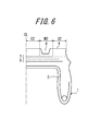
- FIG. 6 is a schematic cross sectional view of a half portion of a radial tire according to one embodiment of the present invention.
- FIG. 7 is an explanatory diagram of tire-width-direction center portions C 1 , C 2 , tire-width-direction intermediate portions M 1 , M 2 , and tire-width-direction outer portions S 1 , S 2 .
- a tire cross sectional width SW (see FIG. 1 ) of a radial tire smaller than that of the conventional radial tire ensures a wide free space in a vehicle, a wide space for accommodating a driving member in vicinities on the vehicle-inner side of the tire in particular (see FIGS. 2A and 2B ).
- a tire cross sectional width SW of a radial tire smaller than that of the conventional radial tire also causes a good effect of reducing an air resistance value (Cd value) of the vehicle because an area of the tire viewed from the front thereof decreases.
- a rolling resistance value (RR value) of the tire increases due to an increase in magnitude of deformation of a ground contact portion of a tread when the internal air pressure of the tire remains the same.
- the inventors of the present invention in view of the aforementioned situation, discovered that the problem can be solved by utilizing the characteristics inherent to a radial tire. Specifically, the inventors of the present invention realized that, in the case of a radial tire having a smaller magnitude of tread deformation than a bias tire, it is possible to make the radial tire be less affected by a rough road surface and thus reduce a rolling resistance value (RR value) thereof when the internal air pressure remains the same by increasing the outer diameter OD (see FIG. 1 ) of the radial tire as compared with the conventional radial tire. Further, the inventors of the present invention also realized that an increase in outer diameter OD of a radial tire enhances the loading capacity of the tire.
- an increase in outer diameter of a radial tire increases height of drive shafts to enlarge an under-chassis space, as shown in FIG. 2A , thereby allowing the vehicle to keep wide spaces for a car boot, driving units and the like.
- reducing width and increasing outer diameter of a tire effectively ensure a wide space in a vehicle, respectively, although they are in a trade-off relationship in terms of a rolling resistance value (RR value).
- Reducing tire width also successfully decreases an air resistance value (Cd value) of a vehicle.
- the inventors of the present invention keenly studied optimizing a relationship between a tire cross sectional width and an outer diameter of a tire such that an air resistance value (Cd value) and a rolling resistance value (RR value) of a vehicle improve as compared with the conventional radial tire.
- the inventors of the present invention paying their attention to a relationship between a tire cross sectional width SW and an outer diameter OD of a tire, carried out a test including mounting test tires of various tire sizes (some of them were non-standard products) on a vehicle and measuring an air resistance value (Cd value) and a rolling resistance value (RR value) for each type or size of the test tires.
- Cd value air resistance value
- RR value rolling resistance value
- FIG. 3 is a schematic cross sectional view, in the tire width direction, of a tire used in the aforementioned test.
- FIG. 3 shows only one half portion with respect to the tire equatorial plane CL of the tire.
- the other half portion of the tire shares basically the same structure as the one half portion and therefore illustration thereof will be omitted.
- FIG. 3 shows a tire in a state where the tire has been assembled with a rim and inflated at the air pressure under the maximum load respectively prescribed for each vehicle on which the tire is to be mounted.
- the tire exemplarily shown in FIG. 3 has the carcass 2 constituted of organic fibers, a belt 3 constituted of a plurality of belt layers (two belt layers in FIG. 3 ) and a tread 4 such that the belt 3 and the tread 4 are provided on the outer side in the tire radial direction of a crown portion of the carcass 2 in this order.
- the tire exemplarily shown in FIG. 3 has one belt reinforcing layer 5 as a rubber-coated cord layer in which cords are spirally wound along the tire equatorial plane to extend substantially in the tire circumferential direction such that the belt reinforcing layer 5 is disposed on the outer side in the tire radial direction of the belt layer 3 .
- Young's modulus represents Young's modulus in the tire circumferential direction to be determined by a test according to JIS L1017 8.5 a) (2002) and calculated according to JIS L1017 8.8 (2002) in the present invention.
- a plurality of main grooves 6 each extending in the tire circumferential direction are formed in the tread 4 (one main groove in each half portion of the tire exemplarily shown in FIG. 3 ).
- test tires having various cross sectional widths and outer diameters were prepared based on the tire structures described above.
- Reference tire 1 a tire having tire size: 195/65R15, which tire size is used in vehicles of the most common types and thus suitable for comparison of tire performances.
- Reference tire 2 a tire having tire size: 225/45R17, which is what is called an “inch-up” version of Reference tire 1.
- test tires 1 to 52 and conventional test tires 1 to 9 of various tire sizes. These test tires were each assembled with a rim, inflated at internal pressure of 220 kPa and subjected to the tests described below. Table 1 shows relevant characteristics of the respective test tires.
- tire sizes a variety of tire sizes including the conventional sizes prescribed in JATMA (The Japan Automobile Tyre Manufacturers Association, Inc.) in Japan, TRA (THE TIRE and RIM ASSOCIATION INC.) in the United States, ETRTO (European Tyre and Rim Technical Organisation) in Europe and the like and those beyond these conventional sizes were widely studied.
- JATMA The Japan Automobile Tyre Manufacturers Association, Inc.
- TRA TIRE and RIM ASSOCIATION INC.
- ETRTO European Tyre and Rim Technical Organisation
- Rolling resistance was measured by: assembling each of the test tires described above with a rim to obtain a tire-rim assembly inflated at internal pressure as shown in Tables 2-1 and 2-2; excreting on the tire-rim assembly the maximum load prescribed for a vehicle on which the tire is mounted; and running the tire at drum rotation speed of 100 km/hour to measure a rolling resistance thereof.
- the evaluation results are shown as index values relative to “100” of Reference tire 1. The smaller index value represents the smaller rolling resistance.
- borderlines borderlines according to linear equations
- RR value rolling resistance value
- Cd value air resistance value
- test tires 1 to 18 were tested for each of test tires 1 to 18 in order to evaluate fuel efficiency and comfortability (degree of free space) of a vehicle on which the tire was mounted.
- test tires 1 to 7, 12 and 17 (see FIGS. 4A and 4B ) satisfying at least one of relationship formulae (1) and relationship formula (2) unanimously exhibited better results than Reference tire 1 in both fuel efficiency and comfortability.
- the inventors of the present invention revealed from the findings described above that it is possible to reduce both air resistance value and rolling resistance value of a pneumatic radial tire in a state where the tire is mounted on a vehicle and also enhance fuel efficiency and comfortability of the vehicle by setting cross sectional width SW and outer diameter OD of the tire to satisfy the aforementioned relationship formulae (1) and/or relationship formula (2).
- the inventors of the present invention also realized that the tire satisfying the aforementioned relationship formulae (1) and/or relationship formula (2) exhibits increases in belt tension and ring rigidity thereof due to a relatively large outer diameter and experiences higher ground contact pressure in the vicinities of ground contact ends than in other portions thereof due to a relatively narrow width, thereby becoming sensitive to force inputted from a road surface to exhibit deteriorated low-noise properties, i.e. causing a problem which typically occurs in a tire having narrow width and large outer diameter.
- the inventors therefore keenly studied to solve the problem and discovered a tire structure which can successfully solve the problem.
- the tire structure for improving low-noise properties of a pneumatic radial tire for a passenger vehicle satisfying the aforementioned relationship formulae (1) and/or relationship formula (2) thus discovered will be described hereinafter.
- FIG. 6 is a schematic cross sectional view, in the tire width direction, of a tire according to one embodiment of the present invention.
- FIG. 6 shows only one half portion with respect to the tire equatorial plane CL of the tire.
- the other half portion of the tire shares basically the same structure as the one half portion and therefore illustration thereof will be omitted.
- FIG. 6 shows a tire in a state where the tire has been assembled with a rim and inflated at the air pressure under the maximum load respectively prescribed for each vehicle on which the tire is to be mounted.
- the tire shown in FIG. 6 has a pair of bead portions 1 , a carcass 2 provided to extend in a toroidal shape across the pair of bead portions 1 , and a belt 8 constituted of a plurality of belt layers (two belt layers in FIG. 6 ) and a belt reinforcing layer 7 (a single layer in FIG. 6 ) and a tread 4 such that the belt 8 , the belt reinforcing layer 7 and the tread 4 are provided on the outer side in the tire radial direction of the carcass 2 in this order.
- the number of belt layers constituting the belt 8 preferably does not exceed two and the belt reinforcing layer 7 is constituted of at least one layer, preferably one or two layers (a single layer in the embodiment shown in FIG. 6 ).
- the tire shown in FIG. 6 is different from the tire shown in FIG. 3 in that rigidity in the tire circumferential direction of the belt reinforcing layer 7 varies depending on positions in the tire width direction thereof in the former.
- each half portion in the tire width direction of a ground contact surface of the tire is divided in the tire width direction into three equal portions including a tire-width-direction center portion C 1 (C 2 ), a tire-width-direction intermediate portion M 1 (M 2 ) and a tire-width-direction outer portion S 1 (S 2 ) from the tire-width-direction center side, as shown in FIG. 7 , rigidity in the tire circumferential direction of the belt reinforcing layer 7 in a region in the tire width direction thereof corresponding to the tire-width-direction outer side portion S 1 (S 2 ) (see FIG.
- the cord implantation number of the belt reinforcing layer in a region in the tire width direction thereof corresponding to the tire-width-direction outer side portion S 1 (S 2 ) may be smaller than that in a region in the tire width direction thereof corresponding to the tire-width-direction center portion C 1 (C 2 ).
- the number of the belt reinforcing layers in a region in the tire width direction thereof corresponding to the tire-width-direction outer side portion S 1 (S 2 ) may be smaller than that in a region in the tire width direction thereof corresponding to the tire-width-direction center portion C 1 (C 2 ).
- rigidity in the tire circumferential direction of the tread at a position in the tire width direction thereof corresponding to the tire-width-direction outer side portion S 1 , S 2 is lower than rigidity in the tire circumferential direction of the tread at a position in the tire width direction thereof corresponding to the tire-width-direction center portion C 1 , C 2 .
- occurrence of slips in the vicinities of ground contact ends of the tire is suppressed when lateral force is exerted thereon and thus cornering power of a vehicle enhances, as a result of the mitigation of concentration of ground contact pressure on vicinities of ground contact ends of the tire according to the present invention, although the enhancement of cornering power is not the primary object of the present invention.
- wear resistance of the tire improves because occurrence of slips in the vicinities of ground contact ends of the tire is suppressed as described above and rotations per minute of the tire in running decrease due to an increase in outer diameter, i.e. an increase in ground contact length, of the tire.
- Rigidity X 1 in the tire circumferential direction of the belt reinforcing layer 7 in a region in the tire width direction thereof corresponding to the tire-width-direction outer side portion S 1 , S 2 is preferably 75% of rigidity X 2 in the tire circumferential direction of the belt reinforcing layer 7 in a region in the tire width direction thereof corresponding to the tire-width-direction center portion C 1 , C 2 because then a distribution in the tire width direction of ground contact pressure can be effectively made even.
- rigidity X 1 in the tire circumferential direction of the belt reinforcing layer 7 in a region in the tire width direction thereof corresponding to the tire-width-direction outer side portion S 1 , S 2 is preferably ⁇ 30% of rigidity X 2 in the tire circumferential direction of the belt reinforcing layer 7 in a region in the tire width direction thereof corresponding to the tire-width-direction center portion C 1 , C 2 because too low rigidities in the tire circumferential direction of belt end portions increase interlayer shearing strains at steel belt ends and decrease durability thereof.
- Rigidity in the tire circumferential direction of the belt reinforcing layer in a region in the tire width direction thereof corresponding to the tire-width-direction intermediate portion may be either: equal to rigidity in the tire circumferential direction of the belt reinforcing layer in a region in the tire width direction thereof corresponding to the tire-width-direction center portion; or equal to rigidity in the tire circumferential direction of the belt reinforcing layer in a region in the tire width direction thereof corresponding to the tire-width-direction outer side portion; or around the intermediate value between these two rigidities.
- the total (average) rigidity of the belt reinforcing layer in the regions thereof corresponding to the tire-width-direction intermediate portion M 1 (M 2 ) and the tire-width-direction outer side portion S 1 (S 2 ) in each half portion in the tire width direction of a ground contact surface of the tire is preferably ⁇ 87.5% of the total (average) rigidity of the belt reinforcing layer in the regions thereof corresponding to the two tire-width-direction center portions C 1 , C 2 in terms of making a distribution of ground contact pressure uniform.
- the cord implantation number n (number of cords/50 mm) of the belt reinforcing layer 7 in a region in the tire width direction thereof corresponding to the tire-width-direction outer side portion S 1 , S 2 is preferably 0.3 to 0.75 times as large as the cord implantation number n (number of cords/50 mm) of the belt reinforcing layer 7 in a region in the tire width direction thereof corresponding to the tire-width-direction center portion C 1 , C 2 .
- the cord implantation number n of the belt reinforcing layer 7 in a region in the tire width direction thereof corresponding to the tire-width-direction outer side portion S 1 , S 2 is preferably ⁇ 0.75 ⁇ the cord implantation number n of the belt reinforcing layer 7 in a region in the tire width direction thereof corresponding to the tire-width-direction center portion C 1 , C 2 because then a distribution in the tire width direction of ground contact pressure can be effectively made even.
- the former cord implantation number is preferably ⁇ 0.3 ⁇ the latter cord implantation number because then good durability of belt ends can be ensured.
- a ratio W/TW of a width W in the tire width direction of the belt reinforcing layer with respect to a tread width TW preferably satisfies the formula below in the present invention.
- the belt reinforcing layer as a reinforcing member can adequately suppress deformation of the tread between a ground contact surface and the steel belt and thus well suppress an increase in rolling resistance of the tire when the ratio W/TW is ⁇ 0.9. Further, it is possible to mitigate uneven distributions of ground contact pressure and shearing force in vicinities of the ground contact ends caused by excessive constraint in the tire circumferential direction by the belt reinforcing layer, so that good wear resistance is ensured, by setting the ratio W/TW to be ⁇ 1.1.
- Young's modulus of the cords for use in the belt reinforcing layer is preferably in the range of 3 GPa to 20 GPa in the present invention so that the cords as reinforcing members in the tire circumferential direction having Young's modulus corresponding to desired rigidity in the tire circumferential direction can be effectively disposed in the tire width direction.
- the cords are preferably formed by using organic fibers or the like such as Kevlar® having fineness: 1000 to 1800 dtex so that a wide range of rigidity distribution can be realized by changing high rigidity cords and varying the implantation number thereof in the belt reinforcing layer.
- the belt layer is preferably constituted of belt cords extending to be inclined at an angle ⁇ 45° with respect to the tire circumferential direction such that belt cords of one layer intersect belt cords of the other layer alternately. That is, the belt layer is preferably formed as a two-layered slant belt layer.
- the belt layer preferably has the structure described above because the belt cords disposed to be inclined at a large angel with respect to the tire circumferential direction decrease out-of-plane bending rigidity in the tire circumferential direction of the tread, increases elongation in the tire circumferential direction of rubber when a ground contact surface of the tread is deformed and thus successfully suppresses a decrease in ground contact length of the tire, thereby well improving cornering power and partial wear resistance of the tire.
- the inclination angle of the belt cords of the belt layer with respect to the tire circumferential direction is preferably ⁇ 75° in terms of avoiding an increase in rolling resistance and deterioration of wear resistance caused by a too long ground contact length in the tire circumferential direction.
- the tire of the present invention preferably has air volume ⁇ 15,000 cm 3 because a tire for a passenger vehicle must have an air volume ⁇ 15,000 cm 3 in order to reliably have the minimum loading capacity essentially required of a passenger car running on public roads.
- Test tires of Examples 1 to 13 and test tires of Comparative Examples 1, 2 were prepared and subjected to tests for evaluating various performances of the tires in order to confirm an effect of the present invention.
- Each of the test tires has basically the same structure as the tire shown in FIG. 6 .
- the belt reinforcing layer 7 of each test tire is a slant belt layer where belt cords of one layer intersect belt cords of the other layer alternately.
- An angle at which the belt cords of each belt cord layer are inclined with respect to the tire circumferential direction (the same angle value in the one layer and the other layer described above) is shown in Tables 4 and 5 for each of the test tires.
- Each test tire has the belt 8 made of steel cords. Type of a material, Young's modulus and the cord implantation number of the belt reinforcing layer 7 , as well as other detailed characteristics, of each of the test tires are also shown in Tables 4 and 5.
- “Position corresponding to the center portion” represents a region in the tire width direction, of the belt reinforcing layer 7 , corresponding to the tire-width-direction center portion C 1 , C 2 and “Position corresponding to the outer side portion” represents a region in the tire width direction, of the belt reinforcing layer 7 , corresponding to the tire-width-direction outer side portion S 1 , S 2 in Tables 4 and 5.
- “Ratio of rigidity in the circumferential direction” represents a ratio of rigidity in the tire circumferential direction of the belt reinforcing layer in a region in the tire width direction thereof corresponding to the tire-width-direction outer side portion with respect to rigidity in the tire circumferential direction of the belt reinforcing layer in a region in the tire width direction thereof corresponding to the tire-width-direction center portion in Tables 4 and 5.
- “Belt cord inclination angle” represents an angle formed by the belt cords with respect to the tire circumferential direction in Tables 4 and 5.
- Example 12 Example 13 Relationship formulae (1) Satisfied Satisfied Satisfied Satisfied Satisfied Satisfied Satisfied Relationship formula (2) Satisfied Satisfied Satisfied Satisfied Satisfied Satisfied Satisfied Satisfied Tire size 155/55R21 155/55R21 155/55R21 155/55R21 155/55R21 155/55R21 155/60R17 185/50R20 SW/OD 0.22 0.22 0.22 0.22 0.22 0.22 0.25 0.27 Belt Material Nylon Nylon Nylon Nylon Nylon Nylon Nylon Nylon Nylon Nylon Nylon reinforcing Young's 3.4 3.4 3.4 3.4 3.4 3.4 3.4 3.4 3.4 3.4 3.4 3.4 3.4 3.4 3.4 3.4 3.4 3.4 3.4 3.4 3.4 3.4 3.4 3.4 3.4 3.4 3.4 3.4 3.4 3.4 3.4 3.4 3.4 3.4 3.4 3.4 3.4 3.4 3.4 3.4
- Cornering power of each test tire was measured by using a flat belt type tire testing apparatus for measuring the cornering characteristics thereof under the conditions of tire internal pressure: 220 kPa, load exerted on the tire: 3.5 kN and speed: 100 km/hour.
- the cornering power values thus measured were converted to index values relative to the cornering power value “100” of Comparative Example 2 tire for evaluation.
- the larger index value represents the larger and thus more preferable cornering power.
- Wear resistance of each test tire was determined by: running the tire 30,000 km on a drum testing machine under the conditions of tire internal pressure: 220 kPa, load exerted on the tire: 3.5 kN and speed: 80 km/hour; and measuring a remaining groove depth after the running on the drum as a wear resistance value.
- the wear resistance values thus measured were converted to index values relative to the wear resistance value “100” of Comparative Example 2 tire for evaluation. The larger index value represents the better wear resistance.
- Partial wear resistance of each test tire was determined by: running the tire 30,000 km on a drum testing machine under the conditions of tire internal pressure: 220 kPa, load exerted on the tire: 3.5 kN and speed: 80 km/hour; and measuring difference in amount of wear between a tread center portion and a tread end portion after the running on the drum as a partial wear resistance value.
- the partial wear resistance values thus measured were converted to index values relative to the partial wear resistance value “100” of Comparative Example 2 tire for evaluation. The smaller index value represents the better partial wear resistance.
- ⁇ In-Use Fuel Economy> A fuel efficiency test was carried out as described above and the fuel efficiency values thus measured were expressed as index values relative to the fuel efficiency value “100” of Comp. Example 2 for evaluation.
- the larger index value represents the better fuel efficiency.
- ⁇ Comfortability> Comfortability or space availability in a vehicle was determined as described above and the comfortability values thus determined were expressed as index values relative to the comfortability value “100” of Comp. Example 2 for evaluation.
- the larger index value represents the better comfortability or space availability.
- Example 11 Example 12
- Example 13 Low-noise 83 84 86 87 90 88 89 90 properties Cornering power 106 105 104 104 110 112 102 102 Wear resistance 105 105 102 104 106 108 102 102 Partial 94 94 97 98 93 90 98 97 wear resistance In-use fuel 104 102 108 109 108 110 104 103 economy
- Example 2 in which the ratio of rigidity in the tire circumferential direction of the belt reinforcing layer in the tire-width-direction outer side portion thereof with respect to that in the tire-width-direction center portion thereof has been optimized by setting preferable cord implantation numbers of the belt reinforcing layer in the tire-width-direction center portion and the tire-width-direction outer side portion thereof, respectively, exhibits better low-noise properties, cornering power, wear resistance and partial wear resistance than the tire of Example 3.
- Example 11 having a more preferable angle between the belt cords and the tire circumferential direction exhibits better cornering power and wear resistance than the tire of Example 10.
Abstract
Description
Further, the inventors newly discovered that it is effective in a radial tire having small width and large diameter to appropriately control distribution, in the tire width direction, of rigidity in the circumferential direction of a belt reinforcing layer in terms of improving low-noise properties of the tire.
OD≥2.135×SW+282.3; and
X=Y×n×W×m
The cord implantation number of the belt reinforcing layer in a region in the tire width direction thereof corresponding to the tire-width-direction center portion is to be calculated as the average cord implantation number over the region in the tire width direction. The cord implantation number of the belt reinforcing layer in a region in the tire width direction thereof corresponding to the tire-width-direction outer portion is to be calculated in the same manner in this connection.
OD≥−0.0187×SW 2+9.15×SW−380; and
A tire cross sectional width SW of a radial tire smaller than that of the conventional radial tire also causes a good effect of reducing an air resistance value (Cd value) of the vehicle because an area of the tire viewed from the front thereof decreases.
However, there is a demerit in this case in that a rolling resistance value (RR value) of the tire increases due to an increase in magnitude of deformation of a ground contact portion of a tread when the internal air pressure of the tire remains the same.
The tire exemplarily shown in
“Young's modulus” represents Young's modulus in the tire circumferential direction to be determined by a test according to JIS L1017 8.5 a) (2002) and calculated according to JIS L1017 8.8 (2002) in the present invention.
A plurality of
A number of test tires having various cross sectional widths and outer diameters were prepared based on the tire structures described above.
First, there was prepared as Reference tire 1 a tire having tire size: 195/65R15, which tire size is used in vehicles of the most common types and thus suitable for comparison of tire performances. There was also prepared as Reference tire 2 a tire having tire size: 225/45R17, which is what is called an “inch-up” version of
Further, there were also prepared other test tires (
Table 1 shows relevant characteristics of the respective test tires.
With regard to tire sizes, a variety of tire sizes including the conventional sizes prescribed in JATMA (The Japan Automobile Tyre Manufacturers Association, Inc.) in Japan, TRA (THE TIRE and RIM ASSOCIATION INC.) in the United States, ETRTO (European Tyre and Rim Technical Organisation) in Europe and the like and those beyond these conventional sizes were widely studied.
| TABLE 1-1 | |||||
| Tire size | SW (mm) | OD (mm) | SW/OD | ||
| Conventional tire 1 | 145/70R12 | 145 | 507.8 | 0.29 |
| Conventional tire 2 | 155/55R14 | 155 | 526.1 | 0.29 |
| Conventional tire 3 | 165/60R14 | 165 | 553.6 | 0.30 |
| Conventional tire 4 | 175/65R14 | 175 | 583.1 | 0.30 |
| Conventional tire 5 | 185/60R15 | 185 | 603 | 0.31 |
| Conventional tire 6 | 205/55R16 | 205 | 631.9 | 0.32 |
| Conventional tire 7 | 215/60R16 | 215 | 664.4 | 0.32 |
| Conventional tire 8 | 225/55R17 | 225 | 679.3 | 0.33 |
| Conventional tire 9 | 245/45R18 | 245 | 677.7 | 0.36 |
| Reference tire 1 | 195/65R15 | 195 | 634.5 | 0.31 |
| Reference tire 2 | 225/45R17 | 225 | 634.3 | 0.35 |
| Test tire 1 | 155/55R21 | 155 | 704.5 | 0.22 |
| Test tire 2 | 165/55R21 | 165 | 717.4 | 0.23 |
| Test tire 3 | 155/55R19 | 155 | 653.1 | 0.24 |
| Test tire 4 | 155/70R17 | 155 | 645.8 | 0.24 |
| Test tire 5 | 165/55R20 | 165 | 689.5 | 0.24 |
| Test tire 6 | 165/65R19 | 165 | 697.1 | 0.24 |
| Test tire 7 | 165/70R18 | 165 | 687.5 | 0.24 |
| Test tire 8 | 165/55R16 | 165 | 589.3 | 0.28 |
| Test tire 9 | 175/65R15 | 175 | 625.0 | 0.28 |
| Test tire 10 | 185/60R17 | 185 | 660.7 | 0.28 |
| Test tire 11 | 195/65R17 | 195 | 696.4 | 0.28 |
| Test tire 12 | 205/60R18 | 205 | 732.1 | 0.28 |
| Test tire 13 | 185/50R16 | 185 | 596.8 | 0.31 |
| Test tire 14 | 205/60R16 | 205 | 661.3 | 0.31 |
| Test tire 15 | 215/60R17 | 215 | 693.5 | 0.31 |
| Test tire 16 | 225/65R17 | 225 | 725.8 | 0.31 |
| Test tire 17 | 155/45R21 | 155 | 672.9 | 0.23 |
| Test tire 18 | 205/55R16 | 205 | 631.9 | 0.32 |
| Test tire 19 | 165/65R19 | 165 | 697.1 | 0.24 |
| Test tire 20 | 155/65R18 | 155 | 658.7 | 0.24 |
| TABLE 1-2 | |||||
| Tire size | SW (mm) | OD (mm) | SW/OD | ||
| Test tire 21 | 145/65R19 | 145 | 671.1 | 0.22 |
| Test tire 22 | 135/65R19 | 135 | 658.1 | 0.21 |
| Test tire 23 | 125/65R19 | 125 | 645.1 | 0.19 |
| Test tire 24 | 175/55R22 | 175 | 751.3 | 0.23 |
| Test tire 25 | 165/55R20 | 165 | 689.5 | 0.24 |
| Test tire 26 | 155/55R19 | 155 | 653.1 | 0.24 |
| Test tire 27 | 145/55R20 | 145 | 667.5 | 0.22 |
| Test tire 28 | 135/55R20 | 135 | 656.5 | 0.21 |
| Test tire 29 | 125/55R20 | 125 | 645.5 | 0.19 |
| Test tire 30 | 175/45R23 | 175 | 741.7 | 0.24 |
| Test tire 31 | 165/45R22 | 165 | 707.3 | 0.23 |
| Test tire 32 | 155/45R21 | 155 | 672.9 | 0.23 |
| Test tire 33 | 145/45R21 | 145 | 663.9 | 0.22 |
| Test tire 34 | 135/45R21 | 135 | 654.9 | 0.21 |
| Test tire 35 | 145/60R16 | 145 | 580.4 | 0.25 |
| Test tire 36 | 155/60R17 | 155 | 617.8 | 0.25 |
| Test tire 37 | 165/55R19 | 165 | 664.1 | 0.25 |
| Test tire 38 | 155/45R18 | 155 | 596.7 | 0.26 |
| Test tire 39 | 165/55R18 | 165 | 638.7 | 0.26 |
| Test tire 40 | 175/55R19 | 175 | 675.1 | 0.26 |
| Test tire 41 | 115/50R17 | 115 | 546.8 | 0.21 |
| Test tire 42 | 105/50R16 | 105 | 511.4 | 0.21 |
| Test tire 43 | 135/60R17 | 135 | 593.8 | 0.23 |
| Test tire 44 | 185/60R20 | 185 | 730 | 0.25 |
| Test tire 45 | 185/50R20 | 185 | 693.0 | 0.27 |
| Test tire 46 | 195/60R19 | 195 | 716.6 | 0.27 |
| Test tire 47 | 175/60R18 | 175 | 667.2 | 0.26 |
| Test tire 48 | 195/55R20 | 195 | 722.5 | 0.27 |
| Test tire 49 | 215/50R21 | 215 | 748.4 | 0.29 |
| Test tire 50 | 205/55R20 | 205 | 733.5 | 0.28 |
| Test tire 51 | 185/45R22 | 185 | 716.3 | 0.26 |
| Test tire 52 | 155/65R13 | 155 | 634.3 | 0.29 |
The evaluation results are shown as index values relative to “100” of
The smaller index value represents the smaller rolling resistance.
<Air Resistance (Cd) Value of Vehicle>
Air resistance was determined by: assembling each of the test tires described above with a rim to obtain a tire-rim assembly inflated at internal pressure as shown in Tables 2-1 and 2-2; mounting the tire-rim assembly on a vehicle of 1500 cc displacement; and blasting air on the tire at speed corresponding to 100 km/hour and measuring an air pressure value experienced by the tire by a balance installed on the floor under the tire. The results were converted to index values relative to “100” of
The evaluation results are shown in Tables 2-1, 2-2 and
| TABLE 2-1 | |||||
| Internal | |||||
| pressure | RR value | Cd value | |||
| Tire size | (kPa) | (INDEX) | (INDEX) | ||
| Conventional tire 1 | 145/70R12 | 295 | 108 | 94 |
| Conventional tire 2 | 155/55R14 | 275 | 111.3 | 91 |
| Conventional tire 3 | 165/60R14 | 260 | 108.6 | 93 |
| Conventional tire 4 | 175/65R14 | 245 | 103.6 | 101 |
| Conventional tire 5 | 185/60R15 | 230 | 103.9 | 98 |
| Conventional tire 6 | 205/55R16 | 220 | 101 | 102 |
| Conventional tire 7 | 215/60R16 | 220 | 93 | 104 |
| Conventional tire 8 | 225/55R17 | 220 | 85 | 106 |
| Conventional tire 9 | 245/45R18 | 220 | 80 | 111 |
| Reference tire 1 | 195/65R15 | 220 | 100 | 100 |
| Reference tire 2 | 225/45R17 | 220 | 83 | 106 |
| Test tire 1 | 155/55R21 | 220 | 60 | 90 |
| Test tire 2 | 165/55R21 | 220 | 55 | 94 |
| Test tire 3 | 155/55R19 | 220 | 90 | 90 |
| Test tire 4 | 155/70R17 | 220 | 85 | 95 |
| Test tire 5 | 165/55R20 | 220 | 72 | 97 |
| Test tire 6 | 165/65R19 | 220 | 65 | 97 |
| Test tire 7 | 165/70R18 | 220 | 61 | 98 |
| Test tire 8 | 165/55R16 | 220 | 102 | 92 |
| Test tire 9 | 175/65R15 | 220 | 98 | 97 |
| Test tire 10 | 185/60R17 | 220 | 85 | 99 |
| Test tire 11 | 195/65R17 | 220 | 78 | 100 |
| Test tire 12 | 205/60R18 | 220 | 69 | 102 |
| Test tire 13 | 185/50R16 | 220 | 108 | 97 |
| Test tire 14 | 205/60R16 | 220 | 98 | 102 |
| Test tire 15 | 215/60R17 | 220 | 91 | 103 |
| Test tire 16 | 225/65R17 | 220 | 85 | 105 |
| Test tire 17 | 155/45R21 | 220 | 70 | 90 |
| Test tire 18 | 205/55R16 | 220 | 99 | 102 |
| Test tire 19 | 165/65R19 | 260 | 92.2 | 98 |
| Test tire 20 | 155/65R18 | 275 | 96 | 91 |
| TABLE 2-2 | |||||
| Internal | |||||
| pressure | RR value | Cd value | |||
| Tire size | (kPa) | (INDEX) | (INDEX) | ||
| Test tire 21 | 145/65R19 | 295 | 92.4 | 89 |
| Test tire 22 | 135/65R19 | 315 | 91.6 | 87 |
| Test tire 23 | 125/65R19 | 340 | 88.2 | 85 |
| Test tire 24 | 175/55R22 | 345 | 84.8 | 96 |
| Test tire 25 | 165/55R20 | 260 | 92.6 | 93 |
| Test tire 26 | 155/55R19 | 275 | 96.2 | 91 |
| Test tire 27 | 145/55R20 | 290 | 92.3 | 89 |
| Test tire 28 | 135/55R20 | 310 | 92.4 | 87 |
| Test tire 29 | 125/55R20 | 340 | 87.7 | 85 |
| Test tire 30 | 175/45R23 | 250 | 85.5 | 96 |
| Test tire 31 | 165/45R22 | 255 | 89.7 | 93 |
| Test tire 32 | 155/45R21 | 270 | 93.2 | 91 |
| Test tire 33 | 145/45R21 | 290 | 92.2 | 89 |
| Test tire 34 | 135/45R21 | 310 | 92.1 | 87 |
| Test tire 35 | 145/60R16 | 290 | 93.9 | 89 |
| Test tire 36 | 155/60R17 | 270 | 92.1 | 91 |
| Test tire 37 | 165/55R19 | 255 | 89.4 | 93 |
| Test tire 38 | 155/45R18 | 270 | 92.1 | 91 |
| Test tire 39 | 165/55R18 | 255 | 89.4 | 93 |
| Test tire 40 | 175/55R19 | 250 | 88.7 | 96 |
| Test tire 41 | 115/50R17 | 350 | 86.7 | 83 |
| Test tire 42 | 105/50R16 | 350 | 94.1 | 80 |
| Test tire 43 | 135/60R17 | 300 | 85.6 | 87 |
| Test tire 44 | 185/60R20 | 270 | 73.0 | 98 |
| Test tire 45 | 185/50R20 | 270 | 80.0 | 98 |
| Test tire 46 | 195/60R19 | 258 | 81.3 | 100 |
| Test tire 47 | 175/60R18 | 286 | 84.7 | 96 |
| Test tire 48 | 195/55R20 | 277 | 83.3 | 100 |
| Test tire 49 | 215/50R21 | 250 | 75.0 | 104 |
| Test tire 50 | 205/55R20 | 263 | 78.7 | 102 |
| Test tire 51 | 185/45R22 | 285 | 86.7 | 98 |
| Test tire 52 | 155/65R13 | 220 | 90 | 91 |
SW/OD≤0.26 when SW<165 (mm); and
OD≥2.135×SW+282.3 when SW≥165 (mm)
OD≥−0.0187×SW 2+9.15×SW−380
<Comfortability>
Each of the test tires was mounted on a vehicle having 1.7 m width and the resulting width of the rear trunk was measured. The evaluation results are shown as index values relative to “100” of
The test results thus obtained are shown in Table 3 below.
| TABLE 3 | |||||
| Relationship | Relationship | In-use fuel | |||
| formula (1) | formula (2) | economy | | ||
| Test tire |
| 1 | Satisfied | Satisfied | 117 | 105 |
| |
Satisfied | Satisfied | 119 | 104 |
| |
Satisfied | Satisfied | 105 | 105 |
| |
Satisfied | Satisfied | 107 | 105 |
| Test tire 5 | Satisfied | Satisfied | 112 | 104 |
| |
Satisfied | Satisfied | 114 | 104 |
| Test tire 7 | Satisfied | Satisfied | 116 | 104 |
| Test tire 8 | Not satisfied | Not satisfied | 100 | 104 |
| |
Not satisfied | Not satisfied | 101 | 102 |
| Test tire 10 | Not satisfied | Not satisfied | 106 | 101 |
| Test tire 11 | Not satisfied | Satisfied | 109 | 100 |
| Test tire 12 | Satisfied | Satisfied | 112 | 99 |
| Test tire 13 | Not satisfied | Not satisfied | 97 | 101 |
| Test tire 14 | Not satisfied | Not satisfied | 101 | 99 |
| Test tire 15 | Not satisfied | Not satisfied | 103 | 98 |
| Test tire 16 | Not satisfied | Not satisfied | 106 | 97 |
| Test tire 17 | Satisfied | Satisfied | 116 | 105 |
| Test tire 18 | Not satisfied | Not satisfied | 99 | 99 |
| Reference | — | — | 100 | 100 |
| |
||||
In the tire of the present embodiment, the number of belt layers constituting the belt 8 preferably does not exceed two and the belt reinforcing layer 7 is constituted of at least one layer, preferably one or two layers (a single layer in the embodiment shown in
The tire shown in
Specifically, provided that each half portion in the tire width direction of a ground contact surface of the tire is divided in the tire width direction into three equal portions including a tire-width-direction center portion C1 (C2), a tire-width-direction intermediate portion M1 (M2) and a tire-width-direction outer portion S1 (S2) from the tire-width-direction center side, as shown in
In this connection, for example, Young's modulus of a material for cords of the belt reinforcing layer in a region in the tire width direction thereof corresponding to the tire-width-direction outer side portion S1 (S2) may be lower than that in a region in the tire width direction thereof corresponding to the tire-width-direction center portion C1 (C2). Alternatively, the cord implantation number of the belt reinforcing layer in a region in the tire width direction thereof corresponding to the tire-width-direction outer side portion S1 (S2) may be smaller than that in a region in the tire width direction thereof corresponding to the tire-width-direction center portion C1 (C2). Further alternatively, the number of the belt reinforcing layers in a region in the tire width direction thereof corresponding to the tire-width-direction outer side portion S1 (S2) may be smaller than that in a region in the tire width direction thereof corresponding to the tire-width-direction center portion C1 (C2). Yet further alternatively, the width in the tire width direction of the belt reinforcing layer in a region in the tire width direction thereof corresponding to the tire-width-direction outer side portion S1 (S2) may be narrower than that in a region in the tire width direction thereof corresponding to the tire-width-direction center portion C1 (C2). Yet further alternatively, any of two or more techniques described above may be used in combination such that rigidity in the tire circumferential direction of the belt reinforcing layer in a region in the tire width direction thereof corresponding to the tire-width-direction outer side portion is lower than rigidity in the tire circumferential direction of the belt reinforcing layer in a region in the tire width direction thereof corresponding to the tire-width-direction center portion.
An effect of the present invention will be described hereinafter.
Rigidity in the tire circumferential direction of the belt reinforcing layer in a region in the tire width direction thereof corresponding to the tire-width-direction intermediate portion may be either: equal to rigidity in the tire circumferential direction of the belt reinforcing layer in a region in the tire width direction thereof corresponding to the tire-width-direction center portion; or equal to rigidity in the tire circumferential direction of the belt reinforcing layer in a region in the tire width direction thereof corresponding to the tire-width-direction outer side portion; or around the intermediate value between these two rigidities.
The total (average) rigidity of the belt reinforcing layer in the regions thereof corresponding to the tire-width-direction intermediate portion M1 (M2) and the tire-width-direction outer side portion S1 (S2) in each half portion in the tire width direction of a ground contact surface of the tire is preferably ≤87.5% of the total (average) rigidity of the belt reinforcing layer in the regions thereof corresponding to the two tire-width-direction center portions C1, C2 in terms of making a distribution of ground contact pressure uniform.
0.9≤W/TW·1.1
The belt reinforcing layer as a reinforcing member can adequately suppress deformation of the tread between a ground contact surface and the steel belt and thus well suppress an increase in rolling resistance of the tire when the ratio W/TW is ≥0.9. Further, it is possible to mitigate uneven distributions of ground contact pressure and shearing force in vicinities of the ground contact ends caused by excessive constraint in the tire circumferential direction by the belt reinforcing layer, so that good wear resistance is ensured, by setting the ratio W/TW to be ≤1.1.
In this connection, the inclination angle of the belt cords of the belt layer with respect to the tire circumferential direction is preferably ≤75° in terms of avoiding an increase in rolling resistance and deterioration of wear resistance caused by a too long ground contact length in the tire circumferential direction.
Type of a material, Young's modulus and the cord implantation number of the belt reinforcing layer 7, as well as other detailed characteristics, of each of the test tires are also shown in Tables 4 and 5.
“Position corresponding to the center portion” represents a region in the tire width direction, of the belt reinforcing layer 7, corresponding to the tire-width-direction center portion C1, C2 and “Position corresponding to the outer side portion” represents a region in the tire width direction, of the belt reinforcing layer 7, corresponding to the tire-width-direction outer side portion S1, S2 in Tables 4 and 5.
Further, “Ratio of rigidity in the circumferential direction” represents a ratio of rigidity in the tire circumferential direction of the belt reinforcing layer in a region in the tire width direction thereof corresponding to the tire-width-direction outer side portion with respect to rigidity in the tire circumferential direction of the belt reinforcing layer in a region in the tire width direction thereof corresponding to the tire-width-direction center portion in Tables 4 and 5.
Yet further, “Belt cord inclination angle” represents an angle formed by the belt cords with respect to the tire circumferential direction in Tables 4 and 5.
| TABLE 4 | ||||||||
| Comp. | Comp. | |||||||
| Example 1 | Example 1 | Example 2 | Example 2 | Example 3 | Example 4 | Example 5 | ||
| Relationship formulae (1) | Satisfied | Satisfied | Satisfied | Satisfied | Satisfied | Satisfied | Satisfied |
| Relationship formula (2) | Satisfied | Satisfied | Satisfied | Satisfied | Satisfied | Satisfied | |
| Tire size | |||||||
| 155/ |
195/ |
155/ |
155/ |
155/ |
155/ |
155/55R21 | |
| SW/OD | 0.22 | 0.31 | 0.22 | 0.22 | 0.22 | 0.22 | 0.22 |
| Belt reinforcing | Material | Nylon | Nylon | Nylon | Nylon | Nylon | Kevlar | Kevlar |
| layer (at a | Young's | 3.4 | 3.4 | 3.4 | 3.4 | 3.4 | 11 | 11 |
| position | modulus (GPa) | |||||||
| corresponding | |
50 | 50 | 50 | 50 | 50 | 50 | 50 |
| to the central | implantation | |||||||
| portion) | number | |||||||
| (number/50 mm) | ||||||||
| Belt reinforcing | Material | Nylon | Nylon | Nylon | Nylon | Nylon | Kevlar | Nylon |
| layer (at a | Young's | 3.4 | 3.4 | 3.4 | 3.4 | 3.4 | 11 | 3.4 |
| position | modulus (GPa) | |||||||
| corresponding | |
40 | 40 | 50 | 37.5 | 38.5 | 40 | 50 |
| to the outer | implantation | |||||||
| side portion) | number | |||||||
| (number/50 mm) |
| Rigidity in the circumferential direction (%) | 80 | 80 | 100 | 75 | 77 | 80 | 31 |
| Belt cord inclination angle | 28° | 28° | 28° | 28° | 28° | 28° | 28° |
| W/TW (%) | 100 | 100 | 100 | 100 | 100 | 100 | 100 |
| TABLE 5 | |||||||||
| Example 6 | Example 7 | Example 8 | Example 9 | Example 10 | Example 11 | Example 12 | Example 13 | ||
| Relationship formulae (1) | Satisfied | Satisfied | Satisfied | Satisfied | Satisfied | Satisfied | Satisfied | Satisfied |
| Relationship formula (2) | Satisfied | Satisfied | Satisfied | Satisfied | Satisfied | Satisfied | Satisfied | |
| Tire size | ||||||||
| 155/ |
155/ |
155/ |
155/ |
155/ |
155/ |
155/60R17 | 185/50R20 | |
| SW/OD | 0.22 | 0.22 | 0.22 | 0.22 | 0.22 | 0.22 | 0.25 | 0.27 |
| Belt | Material | Nylon | Nylon | Nylon | Nylon | Nylon | Nylon | Nylon | Nylon | |
| reinforcing | Young's | 3.4 | 3.4 | 3.4 | 3.4 | 3.4 | 3.4 | 3.4 | 3.4 | |
| layer (at a | modulus (GPa) | |||||||||
| | Cord | 50 | 50 | 50 | 50 | 50 | 50 | 50 | 50 | |
| corresponding | implantation | |||||||||
| to the central | number | |||||||||
| portion) | (number/50 mm) | |||||||||
| Belt | Material | Nylon | Nylon | Nylon | Nylon | Nylon | Nylon | Nylon | Nylon | |
| reinforcing | Young's | 3.4 | 3.4 | 3.4 | 3.4 | 3.4 | 3.4 | 3.4 | 3.4 | |
| layer (at a | modulus (GPa) | |||||||||
| | Cord | 40 | 40 | 40 | 40 | 40 | 40 | 40 | 40 | |
| corresponding | implantation | |||||||||
| to the outer | number | |||||||||
| side portion) | (number/50 mm) |
| Rigidity in the circumferential | 80 | 80 | 80 | 80 | 80 | 80 | 80 | 80 |
| direction (%) | ||||||||
| Belt cord inclination angle | 28° | 28° | 28° | 28° | 40° | 45° | 28° | 28° |
| W/TW (%) | 90 | 88 | 112 | 110 | 100 | 100 | 100 | 100 |
The low-noise properties of the test tires are expressed by index values relative to the low-noise property value “100” of Comparative Example 2 tire. The smaller index value represents the better low-noise properties.
<Cornering Power>
Cornering power of each test tire was measured by using a flat belt type tire testing apparatus for measuring the cornering characteristics thereof under the conditions of tire internal pressure: 220 kPa, load exerted on the tire: 3.5 kN and speed: 100 km/hour. The cornering power values thus measured were converted to index values relative to the cornering power value “100” of Comparative Example 2 tire for evaluation. The larger index value represents the larger and thus more preferable cornering power.
<Wear Resistance>
Wear resistance of each test tire was determined by: running the tire 30,000 km on a drum testing machine under the conditions of tire internal pressure: 220 kPa, load exerted on the tire: 3.5 kN and speed: 80 km/hour; and measuring a remaining groove depth after the running on the drum as a wear resistance value. The wear resistance values thus measured were converted to index values relative to the wear resistance value “100” of Comparative Example 2 tire for evaluation. The larger index value represents the better wear resistance.
<Partial Wear Resistance>
Partial wear resistance of each test tire was determined by: running the tire 30,000 km on a drum testing machine under the conditions of tire internal pressure: 220 kPa, load exerted on the tire: 3.5 kN and speed: 80 km/hour; and measuring difference in amount of wear between a tread center portion and a tread end portion after the running on the drum as a partial wear resistance value. The partial wear resistance values thus measured were converted to index values relative to the partial wear resistance value “100” of Comparative Example 2 tire for evaluation. The smaller index value represents the better partial wear resistance.
<In-Use Fuel Economy>
A fuel efficiency test was carried out as described above and the fuel efficiency values thus measured were expressed as index values relative to the fuel efficiency value “100” of Comp. Example 2 for evaluation. The larger index value represents the better fuel efficiency.
<Comfortability>
Comfortability or space availability in a vehicle was determined as described above and the comfortability values thus determined were expressed as index values relative to the comfortability value “100” of Comp. Example 2 for evaluation. The larger index value represents the better comfortability or space availability.
The respective evaluation results are shown in Tables 6 and 7.
| TABLE 6 | ||||||||
| Comp. | Comp. | |||||||
| Example 1 | Example 1 | Example 2 | Example 2 | Example 3 | Example 4 | Example 5 | ||
| Low-noise | 85 | 94 | 100 | 80 | 83 | 90 | 87 |
| properties | |||||||
| Cornering power | 103 | 95 | 100 | 107 | 105 | 107 | 110 |
| Wear resistance | 103 | 98 | 100 | 105 | 104 | 106 | 110 |
| Partial | 96 | 97 | 100 | 93 | 95 | 95 | 90 |
| wear resistance | |||||||
| In-use fuel | 107 | 99 | 100 | 104 | 105 | 110 | 108 |
| economy | |||||||
| TABLE 7 | |||||||||
| Example 6 | Example 7 | Example 8 | Example 9 | Example 10 | Example 11 | Example 12 | Example 13 | ||
| Low-noise | 83 | 84 | 86 | 87 | 90 | 88 | 89 | 90 |
| | ||||||||
| Cornering power | ||||||||
| 106 | 105 | 104 | 104 | 110 | 112 | 102 | 102 | |
| Wear resistance | 105 | 105 | 102 | 104 | 106 | 108 | 102 | 102 |
| Partial | 94 | 94 | 97 | 98 | 93 | 90 | 98 | 97 |
| wear resistance | ||||||||
| In- |
104 | 102 | 108 | 109 | 108 | 110 | 104 | 103 |
| economy | ||||||||
- 1 Bead portion
- 2 Carcass
- 3 Belt layer
- 4 Tread
- 5 Belt reinforcing layer
- 6 Groove
- 7 Belt reinforcing layer
- 8 Belt
- C1, C2 Tire-width-direction center portion
- M1, M2 Tire-width-direction intermediate portion
- S1, S2 Tire-width-direction outer side portion
Claims (22)
OD≥2.135×SW+282.3;
0.30<SW/D≤0.52,
OD≥2.135×SW+282.3;
2.135×SW+282.3≤OD<(1/0.26)×SW,
0.30<SW/D≤0.52,
2.135×SW+282.3≤OD<(1/0.26)×SW, and
Applications Claiming Priority (3)
| Application Number | Priority Date | Filing Date | Title |
|---|---|---|---|
| JP2011241581 | 2011-11-02 | ||
| JP2011-241581 | 2011-11-02 | ||
| PCT/JP2012/007043 WO2013065318A1 (en) | 2011-11-02 | 2012-11-02 | Pneumatic radial tire for passenger car |
Publications (2)
| Publication Number | Publication Date |
|---|---|
| US20140290819A1 US20140290819A1 (en) | 2014-10-02 |
| US10207542B2 true US10207542B2 (en) | 2019-02-19 |
Family
ID=48191690
Family Applications (1)
| Application Number | Title | Priority Date | Filing Date |
|---|---|---|---|
| US14/355,597 Expired - Fee Related US10207542B2 (en) | 2011-11-02 | 2012-11-02 | Pneumatic radial tire for passenger vehicle |
Country Status (5)
| Country | Link |
|---|---|
| US (1) | US10207542B2 (en) |
| EP (1) | EP2781366B1 (en) |
| JP (1) | JP5993863B2 (en) |
| CN (1) | CN103987532B (en) |
| WO (1) | WO2013065318A1 (en) |
Families Citing this family (15)
| Publication number | Priority date | Publication date | Assignee | Title |
|---|---|---|---|---|
| JP6175427B2 (en) * | 2012-04-24 | 2017-08-02 | 株式会社ブリヂストン | Pneumatic tire |
| JP6196494B2 (en) * | 2013-08-09 | 2017-09-13 | 住友ゴム工業株式会社 | Pneumatic tire |
| JP6138663B2 (en) | 2013-10-29 | 2017-05-31 | 株式会社ブリヂストン | tire |
| EP3064373B1 (en) * | 2013-10-29 | 2019-04-10 | Bridgestone Corporation | Pneumatic tire |
| JP2015093551A (en) * | 2013-11-11 | 2015-05-18 | 住友ゴム工業株式会社 | Pneumatic tire |
| JP6185610B2 (en) * | 2016-01-08 | 2017-08-23 | 株式会社ブリヂストン | tire |
| JP6660249B2 (en) * | 2016-05-20 | 2020-03-11 | 株式会社ブリヂストン | tire |
| JP6622651B2 (en) * | 2016-05-20 | 2019-12-18 | 株式会社ブリヂストン | tire |
| JP6986419B2 (en) * | 2017-11-08 | 2021-12-22 | Toyo Tire株式会社 | How to place stud pins on pneumatic tires |
| JP7099190B2 (en) * | 2018-08-30 | 2022-07-12 | 横浜ゴム株式会社 | Pneumatic tires |
| JP7198071B2 (en) * | 2018-12-13 | 2022-12-28 | 株式会社ブリヂストン | Pneumatic radial tires for passenger cars |
| WO2020122165A1 (en) * | 2018-12-13 | 2020-06-18 | 株式会社ブリヂストン | Tire |
| JP2020093680A (en) * | 2018-12-13 | 2020-06-18 | 株式会社ブリヂストン | Automobile pneumatic radial tire |
| JP2020093675A (en) * | 2018-12-13 | 2020-06-18 | 株式会社ブリヂストン | Automobile pneumatic radial tire |
| US20220016929A1 (en) * | 2018-12-13 | 2022-01-20 | Bridgestone Corporation | Pneumatic tire |
Citations (18)
| Publication number | Priority date | Publication date | Assignee | Title |
|---|---|---|---|---|
| US3628587A (en) * | 1970-04-22 | 1971-12-21 | Goodyear Tire & Rubber | Bias-belted tire |
| US3786851A (en) | 1970-03-04 | 1974-01-22 | Uniroyal Sa | Belted pneumatic tires |
| JPS5340903A (en) | 1976-09-22 | 1978-04-13 | Yokohama Rubber Co Ltd:The | Automotive tire |
| US4385653A (en) * | 1979-12-31 | 1983-05-31 | Toyo Rubber Industry Co., Ltd. | Pneumatic tire having a tread constructed of at least two kinds of rubbers |
| JPS61275005A (en) | 1985-04-30 | 1986-12-05 | Bridgestone Corp | Pneumatic radial-ply tire |
| EP0370699A2 (en) | 1988-11-21 | 1990-05-30 | Sumitomo Rubber Industries Ltd. | Vehicle tyre |
| JPH03213404A (en) | 1990-01-16 | 1991-09-18 | Sumitomo Rubber Ind Ltd | Spare tire |
| JPH0740706A (en) | 1993-07-28 | 1995-02-10 | Bridgestone Corp | High performance flat pneumatic radial tire |
| FR2719525A1 (en) | 1994-05-06 | 1995-11-10 | Michelin & Cie | Automobile spare wheel |
| JP2544556B2 (en) | 1991-11-08 | 1996-10-16 | 住友ゴム工業株式会社 | Radial tires for heavy loads |
| BG61716B1 (en) | 1995-09-08 | 1998-04-30 | "Видахим" Ад | Pneumatic tyre for agricultural purposes |
| JPH10309906A (en) | 1986-12-25 | 1998-11-24 | Bridgestone Corp | Method of setting outer profile shape and carcass line of pneumatic radial tire for heavy load |
| US5882450A (en) | 1995-07-14 | 1999-03-16 | Bridgestone/Firestone, Inc. | Radial tire/wheel assembly for high brake heat generated service |
| JP2000190706A (en) | 1998-12-28 | 2000-07-11 | Bridgestone Corp | Pneumatic tire |
| US6481479B1 (en) | 1997-08-25 | 2002-11-19 | The Goodyear Tire & Rubber Company | High aspect agricultural or off-road tire |
| JP2008296864A (en) | 2007-06-04 | 2008-12-11 | Bridgestone Corp | Pneumatic tire |
| JP2010047191A (en) | 2008-08-22 | 2010-03-04 | Bridgestone Corp | Treated member and radial tire |
| JP2010137819A (en) | 2008-12-15 | 2010-06-24 | Toyo Tire & Rubber Co Ltd | Pneumatic tire |
-
2012
- 2012-11-02 CN CN201280061454.9A patent/CN103987532B/en not_active Expired - Fee Related
- 2012-11-02 US US14/355,597 patent/US10207542B2/en not_active Expired - Fee Related
- 2012-11-02 JP JP2013541638A patent/JP5993863B2/en not_active Expired - Fee Related
- 2012-11-02 WO PCT/JP2012/007043 patent/WO2013065318A1/en active Application Filing
- 2012-11-02 EP EP12846418.7A patent/EP2781366B1/en not_active Not-in-force
Patent Citations (18)
| Publication number | Priority date | Publication date | Assignee | Title |
|---|---|---|---|---|
| US3786851A (en) | 1970-03-04 | 1974-01-22 | Uniroyal Sa | Belted pneumatic tires |
| US3628587A (en) * | 1970-04-22 | 1971-12-21 | Goodyear Tire & Rubber | Bias-belted tire |
| JPS5340903A (en) | 1976-09-22 | 1978-04-13 | Yokohama Rubber Co Ltd:The | Automotive tire |
| US4385653A (en) * | 1979-12-31 | 1983-05-31 | Toyo Rubber Industry Co., Ltd. | Pneumatic tire having a tread constructed of at least two kinds of rubbers |
| JPS61275005A (en) | 1985-04-30 | 1986-12-05 | Bridgestone Corp | Pneumatic radial-ply tire |
| JPH10309906A (en) | 1986-12-25 | 1998-11-24 | Bridgestone Corp | Method of setting outer profile shape and carcass line of pneumatic radial tire for heavy load |
| EP0370699A2 (en) | 1988-11-21 | 1990-05-30 | Sumitomo Rubber Industries Ltd. | Vehicle tyre |
| JPH03213404A (en) | 1990-01-16 | 1991-09-18 | Sumitomo Rubber Ind Ltd | Spare tire |
| JP2544556B2 (en) | 1991-11-08 | 1996-10-16 | 住友ゴム工業株式会社 | Radial tires for heavy loads |
| JPH0740706A (en) | 1993-07-28 | 1995-02-10 | Bridgestone Corp | High performance flat pneumatic radial tire |
| FR2719525A1 (en) | 1994-05-06 | 1995-11-10 | Michelin & Cie | Automobile spare wheel |
| US5882450A (en) | 1995-07-14 | 1999-03-16 | Bridgestone/Firestone, Inc. | Radial tire/wheel assembly for high brake heat generated service |
| BG61716B1 (en) | 1995-09-08 | 1998-04-30 | "Видахим" Ад | Pneumatic tyre for agricultural purposes |
| US6481479B1 (en) | 1997-08-25 | 2002-11-19 | The Goodyear Tire & Rubber Company | High aspect agricultural or off-road tire |
| JP2000190706A (en) | 1998-12-28 | 2000-07-11 | Bridgestone Corp | Pneumatic tire |
| JP2008296864A (en) | 2007-06-04 | 2008-12-11 | Bridgestone Corp | Pneumatic tire |
| JP2010047191A (en) | 2008-08-22 | 2010-03-04 | Bridgestone Corp | Treated member and radial tire |
| JP2010137819A (en) | 2008-12-15 | 2010-06-24 | Toyo Tire & Rubber Co Ltd | Pneumatic tire |
Non-Patent Citations (13)
| Title |
|---|
| 600R16 Coker Classic Blackwall Tire as accessed on the Internet Archive at http://web.archive.org/web/20081004230735/http://store.coker.com/600r16-coker-classic-blackwall-tire.html showing the page as of Oct. 4, 2008. * |
| Coker Classic Radial 600R16-Blackwall Tire as accessed at http://www.tiresandwires.com/Coker-Classic-Radial-600R16--Blackwall-Tire_p_69.html on Jan. 11, 2015. * |
| Coker Classic Radial 600R16—Blackwall Tire as accessed at http://www.tiresandwires.com/Coker-Classic-Radial-600R16--Blackwall-Tire_p_69.html on Jan. 11, 2015. * |
| Communication dated Jul. 16, 2015 from the European Patent Office in counterpart application No. 12846418.7. |
| Communication dated Sep. 30, 2015 from the State Intellectual Property Office of the People's Republic of China in counterpart application No. 201280061454.9. |
| Honda Insight (2010 Honda Insight 175/65-15 as accessed from https://www.tirerack.com/tires/SelectTireSize.jsp?autoMake=Honda&autoModel=Insight&autoYear=2010&autoModClar=LX on Apr. 1, 2018). * |
| International Search Report of PCT/JP2012/007043 dated Feb. 5, 2013. |
| Machine translation of JP03-213404 (no date). * |
| Machine translation of JP2000-190706 (no date). * |
| Machine translation of JP2008-296864 (no date). * |
| Machine translation of JP2010-137819 (no date). * |
| Non Final Office Action dated Jun. 7, 2017 issue in U.S. Appl. No. 14/355,738. |
| Spare tyre wheel T165/70D16 Toyota Celica ZZ T23 Coupe 1.8 16V Vt-i Yr 99-02 as accessed from http://www.ebay.com/itm/Spare-tyre-wheel-T165-70D16-Toyota-Celica-ZZ-T23-Coupe-1-8-16V-VT-i-Yr-99-02-/381718694058 on Aug. 17, 2017. * |
Also Published As
| Publication number | Publication date |
|---|---|
| CN103987532B (en) | 2016-06-22 |
| EP2781366A1 (en) | 2014-09-24 |
| JPWO2013065318A1 (en) | 2015-04-02 |
| JP5993863B2 (en) | 2016-09-14 |
| EP2781366B1 (en) | 2017-03-15 |
| US20140290819A1 (en) | 2014-10-02 |
| WO2013065318A1 (en) | 2013-05-10 |
| CN103987532A (en) | 2014-08-13 |
| EP2781366A4 (en) | 2015-08-19 |
Similar Documents
| Publication | Publication Date | Title |
|---|---|---|
| US10207542B2 (en) | Pneumatic radial tire for passenger vehicle | |
| US10000090B2 (en) | Pneumatic radial tire for passenger vehicle | |
| EP3202592B1 (en) | Pneumatic radial tire for passenger vehicle | |
| US10226966B2 (en) | Pneumatic radial tire for passenger vehicle, method for using the tire, and tire-rim assembly including the tire | |
| JP5781610B2 (en) | Pneumatic radial tire for passenger cars and method of using the same | |
| JP6537496B2 (en) | Pneumatic tire | |
| JP5993983B2 (en) | Pneumatic radial tire for passenger cars | |
| AU2014282221B2 (en) | Pneumatic tire | |
| EP2738016B1 (en) | Pneumatic radial tire for a passenger vehicle and method of using the tire | |
| WO2011161854A1 (en) | Pneumatic radial tire for automobiles | |
| EP3059100B1 (en) | Pneumatic tire | |
| US20170355230A1 (en) | Pneumatic Tire | |
| JP6162922B2 (en) | Pneumatic radial tire for passenger cars | |
| EP4357157A1 (en) | Pneumatic radial tire for passenger car | |
| EP4353494A1 (en) | Pneumatic radial tire for passenger vehicle | |
| EP4353497A1 (en) | Pneumatic radial tire for passenger car | |
| JP5519467B2 (en) | Pneumatic radial tire | |
| EP4353496A1 (en) | Pneumatic radial tire for passenger vehicle | |
| WO2012066724A1 (en) | Pneumatic radial tire for use on passenger vehicle | |
| JP2019162912A (en) | Pneumatic tire |
Legal Events
| Date | Code | Title | Description |
|---|---|---|---|
| AS | Assignment |
Owner name: BRIDGESTONE CORPORATION, JAPAN Free format text: ASSIGNMENT OF ASSIGNORS INTEREST;ASSIGNORS:KUWAYAMA, ISAO;MATSUMOTO, HIROYUKI;HATANAKA, SHINTARO;REEL/FRAME:033028/0728 Effective date: 20140501 |
|
| STCF | Information on status: patent grant |
Free format text: PATENTED CASE |
|
| FEPP | Fee payment procedure |
Free format text: MAINTENANCE FEE REMINDER MAILED (ORIGINAL EVENT CODE: REM.); ENTITY STATUS OF PATENT OWNER: LARGE ENTITY |
|
| LAPS | Lapse for failure to pay maintenance fees |
Free format text: PATENT EXPIRED FOR FAILURE TO PAY MAINTENANCE FEES (ORIGINAL EVENT CODE: EXP.); ENTITY STATUS OF PATENT OWNER: LARGE ENTITY |
|
| STCH | Information on status: patent discontinuation |
Free format text: PATENT EXPIRED DUE TO NONPAYMENT OF MAINTENANCE FEES UNDER 37 CFR 1.362 |
|
| FP | Lapsed due to failure to pay maintenance fee |
Effective date: 20230219 |