EP3064112A1 - Locking device and shower room assembly - Google Patents
Locking device and shower room assembly Download PDFInfo
- Publication number
- EP3064112A1 EP3064112A1 EP14906146.7A EP14906146A EP3064112A1 EP 3064112 A1 EP3064112 A1 EP 3064112A1 EP 14906146 A EP14906146 A EP 14906146A EP 3064112 A1 EP3064112 A1 EP 3064112A1
- Authority
- EP
- European Patent Office
- Prior art keywords
- locking
- fixing
- driving wing
- adjusting
- wing portion
- Prior art date
- Legal status (The legal status is an assumption and is not a legal conclusion. Google has not performed a legal analysis and makes no representation as to the accuracy of the status listed.)
- Granted
Links
- 239000004033 plastic Substances 0.000 claims abstract description 9
- 238000009434 installation Methods 0.000 claims description 10
- 239000011521 glass Substances 0.000 description 9
- 239000000463 material Substances 0.000 description 4
- 238000005553 drilling Methods 0.000 description 2
- 239000004677 Nylon Substances 0.000 description 1
- 229910052782 aluminium Inorganic materials 0.000 description 1
- XAGFODPZIPBFFR-UHFFFAOYSA-N aluminium Chemical compound [Al] XAGFODPZIPBFFR-UHFFFAOYSA-N 0.000 description 1
- 238000010276 construction Methods 0.000 description 1
- 238000000354 decomposition reaction Methods 0.000 description 1
- 230000007547 defect Effects 0.000 description 1
- 230000000694 effects Effects 0.000 description 1
- 238000011900 installation process Methods 0.000 description 1
- 238000004519 manufacturing process Methods 0.000 description 1
- 230000013011 mating Effects 0.000 description 1
- 229910052751 metal Inorganic materials 0.000 description 1
- 239000002184 metal Substances 0.000 description 1
- 229920001778 nylon Polymers 0.000 description 1
- 238000010079 rubber tapping Methods 0.000 description 1
- 238000005406 washing Methods 0.000 description 1
Images


Classifications
-
- F—MECHANICAL ENGINEERING; LIGHTING; HEATING; WEAPONS; BLASTING
- F16—ENGINEERING ELEMENTS AND UNITS; GENERAL MEASURES FOR PRODUCING AND MAINTAINING EFFECTIVE FUNCTIONING OF MACHINES OR INSTALLATIONS; THERMAL INSULATION IN GENERAL
- F16B—DEVICES FOR FASTENING OR SECURING CONSTRUCTIONAL ELEMENTS OR MACHINE PARTS TOGETHER, e.g. NAILS, BOLTS, CIRCLIPS, CLAMPS, CLIPS OR WEDGES; JOINTS OR JOINTING
- F16B21/00—Means for preventing relative axial movement of a pin, spigot, shaft or the like and a member surrounding it; Stud-and-socket releasable fastenings
- F16B21/02—Releasable fastening devices locking by rotation
Definitions
- the present invention relates to a small structure for a special purpose built in a building, and particularly to a locking device and a shower room assembly using the locking device.
- a partitioned shower room is a shower space partitioned from a washing room or other buildings by a frame comprising a wall and/or a door being constituted of glass.
- the frame comprising glass in the present invention is named as a shower room assembly.
- a shower room assembly is positioned using at least two walls of other buildings and a ground.
- a shower room assembly is installed against walls; the ground is the reference plane; and the installed shower room assembly should be vertical relative to the ground.
- a shower room is separated from a building space including walls 1 and 2 perpendicular with each other and a ground 3 by a shower room assembly 4.
- the shower room assembly 4 is consisted of a frame and a glass wall and a door that are fixed in the frame.
- the glass door shown in Figure 1 may be a general door or a rail-type sliding door.
- a projection of the shower room assembly in Figure 1 on the ground is right-angled, while some of the projections in the prior arts are arcuate.
- a pair of walls 1 and 2 perpendicular with each other are used in Figure 1 , while some shower rooms are separated using a pair of parallel walls in the prior arts, in which case a projection of the shower room assembly on the ground is a horizontal line.
- an existing shower room assembly is usually designed to include a fixing frame to be fixed to the wall surface and an adjusting frame to be connected with the door panel (such as a glass panel).
- the fixing frame is fixed against the wall; then, vertical frames of the adjusting frame are moved to approach the fixing frame; distances between the fixing frame and upper and lower ends of the vertical frames are adjusted, so that the vertical frames are in the perpendicular positions, and the door panel is also in the perpendicular position; finally, holes are drilled on the vertical frames and the fixing frame, and screws or the like are used to fasten the frames.
- drilling needs at least two people working together and consumes a long time; on the other hand, drilling may destroy frame surfaces which are usually made of aluminum, so that the appearance of the product or even the whole product is scrapped, causing losses to users or manufacturers.
- the main objective of the invention is to provide a locking device that is easy to lock quickly.
- Another objective of the invention is to provide a shower room assembly that can be installed quickly and can effectively prevent damages in the installation process.
- the invention provides a locking device comprising a locking assembly and an adjusting member.
- the locking assembly comprises a fixing member, a locking member and a wrench body.
- the fixing member comprises a rotating chamber.
- the locking member comprises a shaft head portion, a driving wing portion, a main rod portion and a locking head portion sequentially arranged along an axis of the locking member, and is rotatably fixed on the fixing member relative to the fixing member, wherein the driving wing portion is located in the rotating chamber, and the locking head portion extends out of the fixing member and is provided with a locking protrusion, an outer profile of which is rectangular or oblong in a cross section view.
- the wrench body is hinged near the rotating chamber, and has a hand-held portion at one side of a hinge, a first projection perpendicular with the hand-held portion at the other side of the hinge, and a second projection extending in a direction parallel with the wrench body at the other side of the hinge, wherein when the wrench body is at a first position, the first projection restricts the driving wing portion at a first angular position; when the wrench body is at a second position perpendicular with the first position, the second projection drives the driving wing portion to rotate to a second angular position that is at 90 degrees with the first angular position.
- the adjusting member comprises a fixing portion and an adjusting body extending outwards from the fixing portion, wherein a plastic passage opening outwards is formed in the adjusting body.
- a wall of the fixing portion is provided with a guiding portion to be in tight fit with a slideway.
- the driving wing portion has a semi-cylindrical cross section or an equilateral angle steel-like cross section, and the first and second projections are alternately arranged along an axis of the hinge.
- the locking protrusion is a set of raised lines that extend circumferentially along a short side surface or a large curvature surface and are axially and evenly distributed.
- the raised line has a triangular cross section.
- the locking protrusion comprises tapers that extend outwards and radially and are evenly distributed on the short side surface or the large curvature surface.
- the invention provides a shower room assembly comprising a fixing frame and an adjusting frame, the fixing frame being a section bar.
- the adjusting frame comprises both a transverse frame and a vertical frame that are section bars, the vertical frame being inserting-connected with the fixing frame in a transverse direction.
- the transverse frame comprises a vertical wall provided with a wrench body operating window.
- the shower room assembly further comprises a locking device that comprises a locking assembly and an adjusting member.
- the locking assembly comprises a fixing member, a locking member and a wrench body.
- the fixing member comprises a rotating chamber.
- the locking member comprises a shaft head portion, a driving wing portion, a main rod portion and a locking head portion sequentially arranged along an axis of the locking member, and is rotatably fixed on the fixing member relative to the fixing member, wherein the driving wing portion is located in the rotating chamber, and the locking head portion extends out of the fixing member and is provided with a locking protrusion, an outer profile of which is rectangular or oblong in a cross section view.
- the wrench body is hinged near the rotating chamber, and has a hand-held portion at one side of a hinge, a first projection perpendicular with the hand-held portion at the other side of the hinge, and a second projection extending in a direction parallel with the wrench body at the other side of the hinge, wherein when the wrench body is at a first position, the first projection restricts the driving wing portion at a first angular position; when the wrench body is at a second position perpendicular with the first position, the second projection drives the driving wing portion to rotate to a second angular position that is at 90 degrees with the first angular position.
- the locking assembly is fixed to a vertical wall by the fixing member of the locking assembly.
- the adjusting member comprises a fixing portion to be fixed at an end of the fixing frame, and an adjusting body extending from the fixing portion towards the transverse frame, wherein a plastic passage opening outwards is formed in the adjusting body.
- a side wall of a chamber close to an installation wall is provided with a slideway, and a guiding portion is provided on a wall of the fixing portion corresponding to the slideway to be in tight fit with the slideway.
- the transverse frame comprises an enclosed chamber formed by a part of the vertical wall and extending vertically and a semi-open chamber located on the other side of the enclosed chamber.
- the fixing member is fixed in the enclosed chamber.
- the driving wing portion has a semi-cylindrical cross section or an equilateral angle steel-like cross section, and the first and second projections are alternately arranged along an axis of the hinge.
- the locking protrusion is a set of raised lines that extend circumferentially along a short side surface or a large curvature surface and are axially and evenly distributed, and the raised line has a triangular cross section.
- the shower room assembly provided by the invention is suitable for operations on a construction site, can be quickly installed to save manpower and materials and is hard to damage.
- this embodiment shows a transverse line-shaped shower room assembly.
- Locking devices are mounted at four nodes A, B, C and D of the shower room assembly respectively.
- the locking device is used to quickly connect and fix the fixing frame 10 with the adjusting frame.
- the adjusting frame is formed by upper and lower transverse frames 40 and two vertical frames connecting and fixing together.
- a glass door is mounted in the adjusting frame.
- the locking device is consisted of the locking assembly 50 and the adjusting member 20.
- the locking assembly 50 is mounted to the transverse frames 40.
- the adjusting member 20 is mounted to the fixing frames 10. Glass and a glass door are mounted between the transverse frames 40 and the vertical frames 30.
- the fixing frame 10 is a section bar, which, when seen from a cross section view, comprises a chamber enclosed by the installation wall 101 and two sidewalls 102 and having an opening.
- a slideway 103 is provided to the sidewalls close to the installation wall.
- Several oblong holes 104 are provided to the installation wall 101 for fixing the fixing frames 10 to the wall through fasteners.
- the transverse frame 40 is a section bar and includes a vertical wall 401 which is provided with a wrench body operating window 402. On the right side of the vertical wall 401 is provided with an enclosed chamber 403 extending vertically; on the left side thereof a semi-open chamber 404. The vertical wall 401 is also provided with screw holes 405 for fixing self-tapping screws.
- the vertical frame 30 is a section bar and comprises a glass installation groove.
- a through hole 301 for a locking head portion to pass through and an unthreaded hole 302 for connecting the locking assembly 50 are machined at an end of the vertical frame 30.
- the locking device comprises the locking assembly 50 and the adjusting member 20. Mating parts of the locking assembly 50 and the adjusting member 20 are sectioned in Figure 8 .
- the adjusting member 20 comprises a fixing portion 201 and an adjusting body 202 extending outwards from the fixing portion 201, wherein a plastic passage 203 opening outwards is formed in the adjusting body 202.
- the passage 203 has a rectangular or oblong cross section.
- the passage 203 naturally has plasticity; when the adjusting member 20 is made of a rigid material such as metal, plasticity of the passage 203 may be obtained by fixing a tube made of a plastic material and having certain wall thickness in a rectangular or oblong hole having a relatively large dimension.
- a guiding portion 204 is provided on a wall of the fixing portion 201 to be in tight fit with the slideway 103, such that the adjusting member 20 may be mounted at end portions of the fixing frames 10.
- the locking assembly 50 comprises a fixing member, a locking member 60 and a wrench body 70.
- the fixing member comprises a fixing block 51 and a fixing block 52 combined together and a rotating chamber 511.
- the locking member 60 may be rotatably fixed on the fixing member, and the wrench body 70 is hinged near the rotating chamber 511 by a hinge 71.
- the fixing block 51 comprises co-axial semi-circular axial holes 512, 513 provided at the two ends of the rotating chamber 511, and a pinhole 514 provided on an engaging surface with the fixing block 52.
- the fixing block 52 comprises a semi-circular axial hole 521 to cooperate with the semi-circular axial holes 512, a pin 524 to cooperate with the pinhole 514, an unthreaded hole 523 for fixing the fixing member to the vertical wall 401 of the transverse frame 40, and a hole 522 for fixing a hinge shaft of the hinge 71.
- the locking member 60 comprises a shaft head portion 601, a driving wing portion 602, a main rod portion 603 and a locking head portion 604 sequentially arranged along an axis of the locking member 60.
- the driving wing portion 602 comprises a pair of wings 6021, 6022 provided at the two sides in the axial direction.
- the locking head portion 604 is provided with raised lines 6041 that are evenly distributed in the axial direction. When seen from the sectional view, the raised lines 6041 have oblong profiles, and tops thereof are distributed on a large curvature side of the oblong.
- the raised lines 6041 have a triangular cross section.
- the wrench body 70 comprises a hinge hole 701, a hand-held portion 702 at one side of the hinge holes 701, a first projection 703 perpendicular with the hand-held portion 702 at the other side of the hinge holes 701, and a second projection 704 extending in a direction parallel with the wrench body at the other side of the hinge holes 701.
- the first and second projections 703 and 704 are alternately arranged in an axial direction of the hinge holes 701.
- the assembled fixing blocks 51, 52 are installed in the enclosed chamber 403 of the transverse frame 40, and pass the unthreaded hole 302 of the vertical frame 30 and the unthreaded hole 523 of the fixing block 52 through a screw to fix the fixing block 52 at the screw hole 405 of the transverse frame 40, thereby connecting and fixing the vertical frame 30, the locking assembly 50 and the transverse frame 40 together.
- the wrench body 70 is located at the wrench body operating window 402.
- the second projection 704 restricts the wing 6021 of the driving wing portion at the second angular position, whereby the locking head portion 604 and the passage 203 are in clearance fit as shown in the partial sectional view of Figure 8 , that is, the locking head portion 604 can move axially relative to the passage 203.
- the hand-held portion 702 may be operated such that the wrench body 70 is rotated to the first position shown in Figure 18 , whereupon the first projection 703 restricts the wing 6022 of the driving wing portion at the first angular position, that is, the locking member 60 rotates by 90 degrees around its own axis. Accordingly, the raised lines 6041 on the locking head portion 604 are meshed with an inner wall of the plastic passage 203, such that the locking head portion 604 is relatively fixed in the axial direction with respect to the passage 203.
Landscapes
- Engineering & Computer Science (AREA)
- General Engineering & Computer Science (AREA)
- Mechanical Engineering (AREA)
- Residential Or Office Buildings (AREA)
- Bathtubs, Showers, And Their Attachments (AREA)
Abstract
Description
- The present invention relates to a small structure for a special purpose built in a building, and particularly to a locking device and a shower room assembly using the locking device.
- Shower rooms can be divided into an integral type and a partitioned type according to their structures. A partitioned shower room is a shower space partitioned from a washing room or other buildings by a frame comprising a wall and/or a door being constituted of glass. The frame comprising glass in the present invention is named as a shower room assembly.
- Usually a shower room assembly is positioned using at least two walls of other buildings and a ground. In other words, usually a shower room assembly is installed against walls; the ground is the reference plane; and the installed shower room assembly should be vertical relative to the ground.
- Referring to
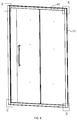
Figure 1 , a shower room is separated from a building space including walls 1 and 2 perpendicular with each other and a ground 3 by a shower room assembly 4. The shower room assembly 4 is consisted of a frame and a glass wall and a door that are fixed in the frame. The glass door shown inFigure 1 may be a general door or a rail-type sliding door. It should be noted that a projection of the shower room assembly inFigure 1 on the ground is right-angled, while some of the projections in the prior arts are arcuate. In addition, a pair of walls 1 and 2 perpendicular with each other are used inFigure 1 , while some shower rooms are separated using a pair of parallel walls in the prior arts, in which case a projection of the shower room assembly on the ground is a horizontal line. - However, walls of buildings sometimes are not perpendicular with the ground. Due to various reasons, the angle between a wall and the ground has a deviation of about 1 degree. If the shower room assembly is installed completely along the walls, opening and closing of the door of the shower room assembly may be affected. Therefore, when installing the shower room assembly, distances between the upper and/or lower ends of the shower room assembly and the wall should be adjusted, so that the door is in the perpendicular position.
- To realize such adjustment, an existing shower room assembly is usually designed to include a fixing frame to be fixed to the wall surface and an adjusting frame to be connected with the door panel (such as a glass panel). When installing, the fixing frame is fixed against the wall; then, vertical frames of the adjusting frame are moved to approach the fixing frame; distances between the fixing frame and upper and lower ends of the vertical frames are adjusted, so that the vertical frames are in the perpendicular positions, and the door panel is also in the perpendicular position; finally, holes are drilled on the vertical frames and the fixing frame, and screws or the like are used to fasten the frames.
- However, on one hand, drilling needs at least two people working together and consumes a long time; on the other hand, drilling may destroy frame surfaces which are usually made of aluminum, so that the appearance of the product or even the whole product is scrapped, causing losses to users or manufacturers.
- The main objective of the invention is to provide a locking device that is easy to lock quickly.
- Another objective of the invention is to provide a shower room assembly that can be installed quickly and can effectively prevent damages in the installation process.
- To realize the above main objective of the invention, the invention provides a locking device comprising a locking assembly and an adjusting member. The locking assembly comprises a fixing member, a locking member and a wrench body. The fixing member comprises a rotating chamber. The locking member comprises a shaft head portion, a driving wing portion, a main rod portion and a locking head portion sequentially arranged along an axis of the locking member, and is rotatably fixed on the fixing member relative to the fixing member, wherein the driving wing portion is located in the rotating chamber, and the locking head portion extends out of the fixing member and is provided with a locking protrusion, an outer profile of which is rectangular or oblong in a cross section view. The wrench body is hinged near the rotating chamber, and has a hand-held portion at one side of a hinge, a first projection perpendicular with the hand-held portion at the other side of the hinge, and a second projection extending in a direction parallel with the wrench body at the other side of the hinge, wherein when the wrench body is at a first position, the first projection restricts the driving wing portion at a first angular position; when the wrench body is at a second position perpendicular with the first position, the second projection drives the driving wing portion to rotate to a second angular position that is at 90 degrees with the first angular position. The adjusting member comprises a fixing portion and an adjusting body extending outwards from the fixing portion, wherein a plastic passage opening outwards is formed in the adjusting body. When the driving wing portion is at the second angular position, the locking head portion is in clearance fit with the passage. When the driving wing portion is at the first angular position, the locking protrusion is meshed into the passage.
- According to a specific solution, a wall of the fixing portion is provided with a guiding portion to be in tight fit with a slideway.
- According to another specific solution, the driving wing portion has a semi-cylindrical cross section or an equilateral angle steel-like cross section, and the first and second projections are alternately arranged along an axis of the hinge.
- According to yet another specific solution, the locking protrusion is a set of raised lines that extend circumferentially along a short side surface or a large curvature surface and are axially and evenly distributed.
- According to yet another specific solution, the raised line has a triangular cross section.
- According to yet another specific solution, the locking protrusion comprises tapers that extend outwards and radially and are evenly distributed on the short side surface or the large curvature surface.
- To realize another objective of the invention, the invention provides a shower room assembly comprising a fixing frame and an adjusting frame, the fixing frame being a section bar. The adjusting frame comprises both a transverse frame and a vertical frame that are section bars, the vertical frame being inserting-connected with the fixing frame in a transverse direction. The transverse frame comprises a vertical wall provided with a wrench body operating window. The shower room assembly further comprises a locking device that comprises a locking assembly and an adjusting member. The locking assembly comprises a fixing member, a locking member and a wrench body. The fixing member comprises a rotating chamber. The locking member comprises a shaft head portion, a driving wing portion, a main rod portion and a locking head portion sequentially arranged along an axis of the locking member, and is rotatably fixed on the fixing member relative to the fixing member, wherein the driving wing portion is located in the rotating chamber, and the locking head portion extends out of the fixing member and is provided with a locking protrusion, an outer profile of which is rectangular or oblong in a cross section view. The wrench body is hinged near the rotating chamber, and has a hand-held portion at one side of a hinge, a first projection perpendicular with the hand-held portion at the other side of the hinge, and a second projection extending in a direction parallel with the wrench body at the other side of the hinge, wherein when the wrench body is at a first position, the first projection restricts the driving wing portion at a first angular position; when the wrench body is at a second position perpendicular with the first position, the second projection drives the driving wing portion to rotate to a second angular position that is at 90 degrees with the first angular position. The locking assembly is fixed to a vertical wall by the fixing member of the locking assembly. The adjusting member comprises a fixing portion to be fixed at an end of the fixing frame, and an adjusting body extending from the fixing portion towards the transverse frame, wherein a plastic passage opening outwards is formed in the adjusting body. When the driving wing portion is at the second angular position, the locking head portion is in clearance fit with the passage. When the driving wing portion is at the first angular position, the locking protrusion is meshed into the passage.
- According to a specific solution, a side wall of a chamber close to an installation wall is provided with a slideway, and a guiding portion is provided on a wall of the fixing portion corresponding to the slideway to be in tight fit with the slideway. The transverse frame comprises an enclosed chamber formed by a part of the vertical wall and extending vertically and a semi-open chamber located on the other side of the enclosed chamber. The fixing member is fixed in the enclosed chamber.
- According to another specific solution, the driving wing portion has a semi-cylindrical cross section or an equilateral angle steel-like cross section, and the first and second projections are alternately arranged along an axis of the hinge.
- According to yet another specific solution, the locking protrusion is a set of raised lines that extend circumferentially along a short side surface or a large curvature surface and are axially and evenly distributed, and the raised line has a triangular cross section.
- The shower room assembly provided by the invention is suitable for operations on a construction site, can be quickly installed to save manpower and materials and is hard to damage.
-
-
Figure 1 is a schematic view of an existing shower room assembly installed in a building; -
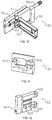
Figure 2 is a perspective view of a shower room assembly according to one embodiment of the present invention; -
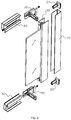
Figure 3 is a structural decomposition view of some members at one side along a line formed by nodes B and D inFigure 2 ; -
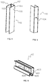
Figure 4 is a perspective view of a fixing frame at node B inFigure 2 ; -
Figure 5 is a perspective view of the fixing frame inFigure 4 from another angle of view; -
Figure 6 is a perspective view of a transverse frame at node B inFigure 3 ; -
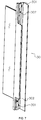
Figure 7 is a perspective view of a vertical frame inFigure 3 ; -
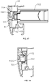
Figure 8 is an enlarged perspective view of a locking device in an assembled but not locked position; -
Figure 9 is a perspective view of an adjusting member inFigure 8 ; -
Figure 10 is a perspective view of a locking assembly inFigure 8 ; -
Figure 11 is a perspective view of a first fixing member inFigure 10 ; -
Figure 12 is a perspective view of a second fixing member inFigure 10 ; -
Figure 13 is a perspective view of a locking member inFigure 10 ; -
Figure 14 is a perspective view of the locking member from another angle of view; -
Figure 15 is a perspective view of a rotating wrench inFigure 10 ; -
Figure 16 is a perspective view of the rotating wrench inFigure 15 from another view; -
Figure 17 is a schematic view when the rotating wrench is at a second position and a rotating wing is at a second angular position; -
Figure 18 is a schematic view when the rotating wrench is at a first position and a rotating wing is at a first angular position; -
Figure 19 is a perspective view before an adjusting frame is mounted to a fixing frame; -
Figure 20 is a perspective view when an adjusting frame is mounted to a fixing frame and is in an adjusting state; -
Figure 21 is a perspective view when an adjusting frame is adjusted and locked. - The present invention is described in detail with reference to the embodiments of the shower room assembly of the present invention and the accompanying drawings. Embodiments of the locking device are also described in detail.
- Referring to
Figure 2 , this embodiment shows a transverse line-shaped shower room assembly. Locking devices are mounted at four nodes A, B, C and D of the shower room assembly respectively. The locking device is used to quickly connect and fix the fixingframe 10 with the adjusting frame. The adjusting frame is formed by upper and lowertransverse frames 40 and two vertical frames connecting and fixing together. A glass door is mounted in the adjusting frame. - Referring to
Figure 3 , the locking device is consisted of the lockingassembly 50 and the adjustingmember 20. The lockingassembly 50 is mounted to the transverse frames 40. The adjustingmember 20 is mounted to the fixing frames 10. Glass and a glass door are mounted between thetransverse frames 40 and the vertical frames 30. - Referring to
Figures 4 and 5 , the fixingframe 10 is a section bar, which, when seen from a cross section view, comprises a chamber enclosed by theinstallation wall 101 and twosidewalls 102 and having an opening. Aslideway 103 is provided to the sidewalls close to the installation wall. Severaloblong holes 104 are provided to theinstallation wall 101 for fixing the fixing frames 10 to the wall through fasteners. - Referring to
Figure 6 , thetransverse frame 40 is a section bar and includes avertical wall 401 which is provided with a wrenchbody operating window 402. On the right side of thevertical wall 401 is provided with anenclosed chamber 403 extending vertically; on the left side thereof asemi-open chamber 404. Thevertical wall 401 is also provided withscrew holes 405 for fixing self-tapping screws. - Referring to
Figure 7 , thevertical frame 30 is a section bar and comprises a glass installation groove. A throughhole 301 for a locking head portion to pass through and anunthreaded hole 302 for connecting the lockingassembly 50 are machined at an end of thevertical frame 30. - Referring to
Figure 8 , the locking device comprises the lockingassembly 50 and the adjustingmember 20. Mating parts of the lockingassembly 50 and the adjustingmember 20 are sectioned inFigure 8 . - Referring to
Figure 9 , the adjustingmember 20 comprises a fixing portion 201 and an adjusting body 202 extending outwards from the fixing portion 201, wherein a plastic passage 203 opening outwards is formed in the adjusting body 202. The passage 203 has a rectangular or oblong cross section. When the adjustingmember 20 is made of a plastic material such as nylon, the passage 203 naturally has plasticity; when the adjustingmember 20 is made of a rigid material such as metal, plasticity of the passage 203 may be obtained by fixing a tube made of a plastic material and having certain wall thickness in a rectangular or oblong hole having a relatively large dimension. A guiding portion 204 is provided on a wall of the fixing portion 201 to be in tight fit with theslideway 103, such that the adjustingmember 20 may be mounted at end portions of the fixing frames 10. - Referring to
Figure 10 , the lockingassembly 50 comprises a fixing member, a lockingmember 60 and awrench body 70. For the sake of manufacturability, the fixing member comprises a fixingblock 51 and a fixingblock 52 combined together and arotating chamber 511. The lockingmember 60 may be rotatably fixed on the fixing member, and thewrench body 70 is hinged near therotating chamber 511 by ahinge 71. - Referring to
Figure 11 , the fixingblock 51 comprises co-axial semi-circularaxial holes rotating chamber 511, and apinhole 514 provided on an engaging surface with the fixingblock 52. - Referring to
Figure 12 , the fixingblock 52 comprises a semi-circularaxial hole 521 to cooperate with the semi-circularaxial holes 512, apin 524 to cooperate with thepinhole 514, anunthreaded hole 523 for fixing the fixing member to thevertical wall 401 of thetransverse frame 40, and ahole 522 for fixing a hinge shaft of thehinge 71. - Referring to
Figures 13 and 14 , the lockingmember 60 comprises ashaft head portion 601, a drivingwing portion 602, amain rod portion 603 and a lockinghead portion 604 sequentially arranged along an axis of the lockingmember 60. The drivingwing portion 602 comprises a pair ofwings head portion 604 is provided with raisedlines 6041 that are evenly distributed in the axial direction. When seen from the sectional view, the raisedlines 6041 have oblong profiles, and tops thereof are distributed on a large curvature side of the oblong. The raisedlines 6041 have a triangular cross section. - Referring to
Figures 15 and 16 , thewrench body 70 comprises ahinge hole 701, a hand-heldportion 702 at one side of the hinge holes 701, afirst projection 703 perpendicular with the hand-heldportion 702 at the other side of the hinge holes 701, and asecond projection 704 extending in a direction parallel with the wrench body at the other side of the hinge holes 701. The first andsecond projections - Referring to
Figure 17 , the assembled fixingblocks enclosed chamber 403 of thetransverse frame 40, and pass theunthreaded hole 302 of thevertical frame 30 and theunthreaded hole 523 of the fixingblock 52 through a screw to fix the fixingblock 52 at thescrew hole 405 of thetransverse frame 40, thereby connecting and fixing thevertical frame 30, the lockingassembly 50 and thetransverse frame 40 together. Thewrench body 70 is located at the wrenchbody operating window 402. When thewrench body 70 is at the second position shown inFigure 17 , thesecond projection 704 restricts thewing 6021 of the driving wing portion at the second angular position, whereby the lockinghead portion 604 and the passage 203 are in clearance fit as shown in the partial sectional view ofFigure 8 , that is, the lockinghead portion 604 can move axially relative to the passage 203. - Referring to
Figure 18 , after the adjusting frame is adjusted to a desirable state relative to the fixingframe 10 and overcomes the defects such as non-vertical walls, the hand-heldportion 702 may be operated such that thewrench body 70 is rotated to the first position shown inFigure 18 , whereupon thefirst projection 703 restricts thewing 6022 of the driving wing portion at the first angular position, that is, the lockingmember 60 rotates by 90 degrees around its own axis. Accordingly, the raisedlines 6041 on the lockinghead portion 604 are meshed with an inner wall of the plastic passage 203, such that the lockinghead portion 604 is relatively fixed in the axial direction with respect to the passage 203. - Referring to
Figure 19 , after thetransverse frame 40, thevertical frame 30, the lockingassembly 50 and the door are assembled into an adjusting frame, fourwrench bodies 70 are placed in the second positions shown inFigure 19 . First, the fixingframe 10 at one side is fixed, and two lockinghead portions 604 at that side are inserted into the corresponding passages 203 shown inFigure 20 ; then, the fixing frame at the other side is fixed to the wall on that side, and two locking head portions at the other side are inserted into the corresponding passages, so that the fixing frames 10 and thevertical frames 30 are connected in an inserting manner. After the adjusting frame is adjusted to a desirable state, the fourwrench bodies 70 are placed in the first positions shown inFigure 21 , completing the installation of the whole shower room assembly. - By applying the structure design of the locking device, installation of the shower room assembly provided by the present invention is very quick, which facilitates manufacturing and installation of the shower room assembly while preventing damages to the shower room assembly during installation.
Claims (10)
- A locking device comprising a locking assembly and an adjusting member, characterized in that:the locking assembly comprises a fixing member, a locking member and a wrench body; the fixing member comprises a rotating chamber; the locking member comprises a shaft head portion, a driving wing portion, a main rod portion and a locking head portion sequentially arranged along an axis of the locking member, and is rotatably fixed on the fixing member relative to the fixing member, wherein the driving wing portion is located in the rotating chamber, and the locking head portion extends out of the fixing member and is provided with a locking protrusion, an outer profile of which is rectangular or oblong in a cross section view; the wrench body is hinged near the rotating chamber, and has a hand-held portion at one side of a hinge, a first projection perpendicular with the hand-held portion at the other side of the hinge, and a second projection extending in a direction parallel with the wrench body at the other side of the hinge, wherein when the wrench body is at a first position, the first projection restricts the driving wing portion at a first angular position; when the wrench body is at a second position perpendicular with the first position, the second projection drives the driving wing portion to rotate to a second angular position that is at 90 degrees with the first angular position;the adjusting member comprises a fixing portion and an adjusting body extending outwards from the fixing portion, wherein a plastic passage opening outwards is formed in the adjusting body;when the driving wing portion is at the second angular position, the locking head portion is in clearance fit with the passage; andwhen the driving wing portion is at the first angular position, the locking protrusion is meshed into the passage.
- The locking device according to claim 1, wherein a wall of the fixing portion is provided with a guiding portion for being in tight fit with a slideway.
- The locking device according to claim 1, wherein the driving wing portion has a semi-cylindrical cross section or an equilateral angle steel-like cross section, and the first and second projections are alternately arranged along an axis of the hinge.
- The locking device according to any one of claims 1-3, wherein the locking protrusion is a set of raised lines that are axially and evenly distributed, and tops of the raised lines are on a short side surface or a large curvature surface.
- The locking device according to claim 4, wherein the raised line has a triangular cross section.
- The locking device according to any one of claims 1-3, wherein the locking protrusion comprises tapers that extend outwards and radially and are evenly distributed on the short side surface or the large curvature surface.
- A shower room assembly, comprising: a fixing frame which is a section bar, and an adjusting frame comprising a transverse frame and a vertical frame that both are section bars, the vertical frame being inserting-connected with the fixing frame in a transverse direction; characterized in that:the transverse frame comprises a vertical wall provided with a wrench body operating window;the shower room assembly further comprises a locking device that comprises a locking assembly and an adjusting member;the locking assembly comprises a fixing member, a locking member and a wrench body; the fixing member comprises a rotating chamber; the locking member comprises a shaft head portion, a driving wing portion, a main rod portion and a locking head portion sequentially arranged along an axis of the locking member, and is rotatably fixed on the fixing member relative to the fixing member, wherein the driving wing portion is located in the rotating chamber, and the locking head portion extends out of the fixing member and is provided with a locking protrusion, an outer profile of which is rectangular or oblong in a cross section view; the wrench body is hinged near the rotating chamber, and has a hand-held portion at one side of a hinge, a first projection perpendicular with the hand-held portion at the other side of the hinge, and a second projection extending in a direction parallel with the wrench body at the other side of the hinge, wherein when the wrench body is at a first position, the first projection restricts the driving wing portion at a first angular position; when the wrench body is at a second position perpendicular with the first position, the second projection drives the driving wing portion to rotate to a second angular position that is at 90 degrees with the first angular position;the locking assembly is fixed to the vertical wall by the fixing member of the locking assembly;the adjusting member comprises a fixing portion to be fixed at an end of the fixing frame, and an adjusting body extending from the fixing portion towards the transverse frame, wherein a plastic passage opening outwards is formed in the adjusting body;when the driving wing portion is at the second angular position, the locking head portion is in clearance fit with the passage; andwhen the driving wing portion is at the first angular position, the locking protrusion is meshed into the passage.
- The shower room assembly according to claim 7, wherein a side wall of a chamber close to an installation wall is provided with a slideway, a guiding portion for being in tight fit with the slideway is provided on a wall of the fixing portion corresponding to the slideway; the transverse frame comprises an enclosed chamber formed by a part of the vertical wall and extending vertically and a semi-open chamber located at the other side of the enclosed chamber; and the fixing member is fixed in the enclosed chamber.
- The shower room assembly according to claim 7, wherein the driving wing portion has a semi-cylindrical cross section or an equilateral angle steel-like cross section, and the first and second projections are alternately arranged along an axis of the hinge.
- The shower room assembly according to any one of claims 7-9, wherein the locking protrusion is a set of raised lines that are axially and evenly distributed; tops of the raised lines are distributed on a short side surface or a large curvature surface; and the raised line has a triangular cross section.
Applications Claiming Priority (1)
| Application Number | Priority Date | Filing Date | Title |
|---|---|---|---|
| PCT/CN2014/092024 WO2016082072A1 (en) | 2014-11-24 | 2014-11-24 | Locking device and shower room assembly |
Publications (3)
| Publication Number | Publication Date |
|---|---|
| EP3064112A1 true EP3064112A1 (en) | 2016-09-07 |
| EP3064112A4 EP3064112A4 (en) | 2016-11-02 |
| EP3064112B1 EP3064112B1 (en) | 2017-05-31 |
Family
ID=53153359
Family Applications (1)
| Application Number | Title | Priority Date | Filing Date |
|---|---|---|---|
| EP14906146.7A Not-in-force EP3064112B1 (en) | 2014-11-24 | 2014-11-24 | Locking device and shower room assembly |
Country Status (3)
| Country | Link |
|---|---|
| EP (1) | EP3064112B1 (en) |
| CN (1) | CN104619224B (en) |
| WO (1) | WO2016082072A1 (en) |
Cited By (1)
| Publication number | Priority date | Publication date | Assignee | Title |
|---|---|---|---|---|
| EP3430959A4 (en) * | 2017-05-24 | 2019-05-22 | Ideal Sanitary Ware Co., Ltd. | Shower door frame, and shower door |
Families Citing this family (2)
| Publication number | Priority date | Publication date | Assignee | Title |
|---|---|---|---|---|
| CN106691265B (en) * | 2017-03-02 | 2023-02-10 | 福建西河卫浴科技有限公司 | Shower room is with easy connecting device and shower room frame |
| CN110115539A (en) * | 2019-03-07 | 2019-08-13 | 福建西河卫浴科技有限公司 | A kind of frame and shower house |
Family Cites Families (8)
| Publication number | Priority date | Publication date | Assignee | Title |
|---|---|---|---|---|
| IT1217333B (en) * | 1988-02-03 | 1990-03-22 | Elia Vismara S R L | Shower cabin having adjustable width |
| US6530186B2 (en) * | 2001-03-20 | 2003-03-11 | Eiler Torstensen | Door framing apparatus and method of use |
| US6701672B2 (en) * | 2001-04-30 | 2004-03-09 | Kohler Co. | Compression mounting system for shower doors |
| GB0607144D0 (en) * | 2006-04-08 | 2006-05-17 | Daryl Ind Ltd | Panel adjustment system |
| AT509796B1 (en) * | 2010-04-30 | 2013-09-15 | Tif Gmbh | HOLLOW PROFILE |
| CN203175264U (en) * | 2013-02-27 | 2013-09-04 | 佛山市爱迪尔卫浴有限公司 | Shower door assembly |
| CN203175265U (en) * | 2013-03-05 | 2013-09-04 | 佛山市爱迪尔卫浴有限公司 | Shower door assembly |
| CN203308298U (en) * | 2013-05-13 | 2013-11-27 | 佛山市理想卫浴有限公司 | Door assembly |
-
2014
- 2014-11-24 WO PCT/CN2014/092024 patent/WO2016082072A1/en active Application Filing
- 2014-11-24 EP EP14906146.7A patent/EP3064112B1/en not_active Not-in-force
- 2014-11-24 CN CN201480001441.1A patent/CN104619224B/en active Active
Cited By (1)
| Publication number | Priority date | Publication date | Assignee | Title |
|---|---|---|---|---|
| EP3430959A4 (en) * | 2017-05-24 | 2019-05-22 | Ideal Sanitary Ware Co., Ltd. | Shower door frame, and shower door |
Also Published As
| Publication number | Publication date |
|---|---|
| CN104619224A (en) | 2015-05-13 |
| EP3064112A4 (en) | 2016-11-02 |
| EP3064112B1 (en) | 2017-05-31 |
| WO2016082072A1 (en) | 2016-06-02 |
| CN104619224B (en) | 2017-09-22 |
Similar Documents
| Publication | Publication Date | Title |
|---|---|---|
| US9167939B2 (en) | Shower door assembly | |
| CA2570091C (en) | Hinge attachment system and method | |
| CA2931720C (en) | Connecting device and shower door assembly including the connecting device | |
| EP3064112B1 (en) | Locking device and shower room assembly | |
| WO2017201589A4 (en) | Curtain wall and set and construction method for such a curtain wall | |
| US20080235910A1 (en) | Hinge | |
| US8910421B2 (en) | Under track garage door seal | |
| CN104704183A (en) | Shower door orbit corner connection device, shower door frame and shower door | |
| CA2841281A1 (en) | Door assembly | |
| US20170254138A1 (en) | Adjustable Door Frame | |
| EP2453068A1 (en) | Detachable connection of mullion and transom profiles | |
| EP2476814B1 (en) | Attic stairs | |
| EP3039207A1 (en) | Leaf of a sliding window or sliding door and sliding window or sliding door provided with such a leaf | |
| KR101496332B1 (en) | Crescents | |
| EP1953331A1 (en) | Housing for a roller shutter box and roller shutter box with such a housing | |
| JP7213715B2 (en) | wall structure | |
| JP2018127861A (en) | Fitting, and method for attaching door body in the same | |
| RU141259U1 (en) | FASTENING MOUNTED STAND | |
| JP5911436B2 (en) | How to install the partition | |
| JP2022175139A (en) | window | |
| WO2012168808A1 (en) | Adjustable spacer | |
| KR20190122611A (en) | Hinge for Folding Door | |
| CH713289A1 (en) | Door frame for concrete component. | |
| BR202015028153U2 (en) | frame mounting kit with sliding door, and drywall and masonry recessed installation system | |
| KR20080065014A (en) | Apparatus for adjusting position of door |
Legal Events
| Date | Code | Title | Description |
|---|---|---|---|
| PUAI | Public reference made under article 153(3) epc to a published international application that has entered the european phase |
Free format text: ORIGINAL CODE: 0009012 |
|
| 17P | Request for examination filed |
Effective date: 20160525 |
|
| AK | Designated contracting states |
Kind code of ref document: A1 Designated state(s): AL AT BE BG CH CY CZ DE DK EE ES FI FR GB GR HR HU IE IS IT LI LT LU LV MC MK MT NL NO PL PT RO RS SE SI SK SM TR |
|
| AX | Request for extension of the european patent |
Extension state: BA ME |
|
| A4 | Supplementary search report drawn up and despatched |
Effective date: 20160929 |
|
| RIC1 | Information provided on ipc code assigned before grant |
Ipc: A47K 3/30 20060101AFI20160923BHEP |
|
| GRAP | Despatch of communication of intention to grant a patent |
Free format text: ORIGINAL CODE: EPIDOSNIGR1 |
|
| STAA | Information on the status of an ep patent application or granted ep patent |
Free format text: STATUS: GRANT OF PATENT IS INTENDED |
|
| INTG | Intention to grant announced |
Effective date: 20161202 |
|
| GRAS | Grant fee paid |
Free format text: ORIGINAL CODE: EPIDOSNIGR3 |
|
| GRAJ | Information related to disapproval of communication of intention to grant by the applicant or resumption of examination proceedings by the epo deleted |
Free format text: ORIGINAL CODE: EPIDOSDIGR1 |
|
| GRAL | Information related to payment of fee for publishing/printing deleted |
Free format text: ORIGINAL CODE: EPIDOSDIGR3 |
|
| STAA | Information on the status of an ep patent application or granted ep patent |
Free format text: STATUS: REQUEST FOR EXAMINATION WAS MADE |
|
| GRAP | Despatch of communication of intention to grant a patent |
Free format text: ORIGINAL CODE: EPIDOSNIGR1 |
|
| STAA | Information on the status of an ep patent application or granted ep patent |
Free format text: STATUS: GRANT OF PATENT IS INTENDED |
|
| INTC | Intention to grant announced (deleted) | ||
| DAX | Request for extension of the european patent (deleted) | ||
| INTG | Intention to grant announced |
Effective date: 20170328 |
|
| GRAA | (expected) grant |
Free format text: ORIGINAL CODE: 0009210 |
|
| STAA | Information on the status of an ep patent application or granted ep patent |
Free format text: STATUS: THE PATENT HAS BEEN GRANTED |
|
| AK | Designated contracting states |
Kind code of ref document: B1 Designated state(s): AL AT BE BG CH CY CZ DE DK EE ES FI FR GB GR HR HU IE IS IT LI LT LU LV MC MK MT NL NO PL PT RO RS SE SI SK SM TR |
|
| REG | Reference to a national code |
Ref country code: CH Ref legal event code: EP Ref country code: GB Ref legal event code: FG4D |
|
| REG | Reference to a national code |
Ref country code: AT Ref legal event code: REF Ref document number: 896677 Country of ref document: AT Kind code of ref document: T Effective date: 20170615 |
|
| REG | Reference to a national code |
Ref country code: IE Ref legal event code: FG4D |
|
| REG | Reference to a national code |
Ref country code: DE Ref legal event code: R096 Ref document number: 602014010413 Country of ref document: DE |
|
| REG | Reference to a national code |
Ref country code: NL Ref legal event code: MP Effective date: 20170531 |
|
| REG | Reference to a national code |
Ref country code: LT Ref legal event code: MG4D |
|
| REG | Reference to a national code |
Ref country code: AT Ref legal event code: MK05 Ref document number: 896677 Country of ref document: AT Kind code of ref document: T Effective date: 20170531 |
|
| PG25 | Lapsed in a contracting state [announced via postgrant information from national office to epo] |
Ref country code: FI Free format text: LAPSE BECAUSE OF FAILURE TO SUBMIT A TRANSLATION OF THE DESCRIPTION OR TO PAY THE FEE WITHIN THE PRESCRIBED TIME-LIMIT Effective date: 20170531 Ref country code: HR Free format text: LAPSE BECAUSE OF FAILURE TO SUBMIT A TRANSLATION OF THE DESCRIPTION OR TO PAY THE FEE WITHIN THE PRESCRIBED TIME-LIMIT Effective date: 20170531 Ref country code: NO Free format text: LAPSE BECAUSE OF FAILURE TO SUBMIT A TRANSLATION OF THE DESCRIPTION OR TO PAY THE FEE WITHIN THE PRESCRIBED TIME-LIMIT Effective date: 20170831 Ref country code: LT Free format text: LAPSE BECAUSE OF FAILURE TO SUBMIT A TRANSLATION OF THE DESCRIPTION OR TO PAY THE FEE WITHIN THE PRESCRIBED TIME-LIMIT Effective date: 20170531 Ref country code: ES Free format text: LAPSE BECAUSE OF FAILURE TO SUBMIT A TRANSLATION OF THE DESCRIPTION OR TO PAY THE FEE WITHIN THE PRESCRIBED TIME-LIMIT Effective date: 20170531 Ref country code: AT Free format text: LAPSE BECAUSE OF FAILURE TO SUBMIT A TRANSLATION OF THE DESCRIPTION OR TO PAY THE FEE WITHIN THE PRESCRIBED TIME-LIMIT Effective date: 20170531 Ref country code: GR Free format text: LAPSE BECAUSE OF FAILURE TO SUBMIT A TRANSLATION OF THE DESCRIPTION OR TO PAY THE FEE WITHIN THE PRESCRIBED TIME-LIMIT Effective date: 20170901 |
|
| REG | Reference to a national code |
Ref country code: FR Ref legal event code: PLFP Year of fee payment: 4 |
|
| PG25 | Lapsed in a contracting state [announced via postgrant information from national office to epo] |
Ref country code: NL Free format text: LAPSE BECAUSE OF FAILURE TO SUBMIT A TRANSLATION OF THE DESCRIPTION OR TO PAY THE FEE WITHIN THE PRESCRIBED TIME-LIMIT Effective date: 20170531 Ref country code: BG Free format text: LAPSE BECAUSE OF FAILURE TO SUBMIT A TRANSLATION OF THE DESCRIPTION OR TO PAY THE FEE WITHIN THE PRESCRIBED TIME-LIMIT Effective date: 20170831 Ref country code: RS Free format text: LAPSE BECAUSE OF FAILURE TO SUBMIT A TRANSLATION OF THE DESCRIPTION OR TO PAY THE FEE WITHIN THE PRESCRIBED TIME-LIMIT Effective date: 20170531 Ref country code: LV Free format text: LAPSE BECAUSE OF FAILURE TO SUBMIT A TRANSLATION OF THE DESCRIPTION OR TO PAY THE FEE WITHIN THE PRESCRIBED TIME-LIMIT Effective date: 20170531 Ref country code: IS Free format text: LAPSE BECAUSE OF FAILURE TO SUBMIT A TRANSLATION OF THE DESCRIPTION OR TO PAY THE FEE WITHIN THE PRESCRIBED TIME-LIMIT Effective date: 20170930 Ref country code: SE Free format text: LAPSE BECAUSE OF FAILURE TO SUBMIT A TRANSLATION OF THE DESCRIPTION OR TO PAY THE FEE WITHIN THE PRESCRIBED TIME-LIMIT Effective date: 20170531 |
|
| PG25 | Lapsed in a contracting state [announced via postgrant information from national office to epo] |
Ref country code: SK Free format text: LAPSE BECAUSE OF FAILURE TO SUBMIT A TRANSLATION OF THE DESCRIPTION OR TO PAY THE FEE WITHIN THE PRESCRIBED TIME-LIMIT Effective date: 20170531 Ref country code: DK Free format text: LAPSE BECAUSE OF FAILURE TO SUBMIT A TRANSLATION OF THE DESCRIPTION OR TO PAY THE FEE WITHIN THE PRESCRIBED TIME-LIMIT Effective date: 20170531 Ref country code: RO Free format text: LAPSE BECAUSE OF FAILURE TO SUBMIT A TRANSLATION OF THE DESCRIPTION OR TO PAY THE FEE WITHIN THE PRESCRIBED TIME-LIMIT Effective date: 20170531 Ref country code: CZ Free format text: LAPSE BECAUSE OF FAILURE TO SUBMIT A TRANSLATION OF THE DESCRIPTION OR TO PAY THE FEE WITHIN THE PRESCRIBED TIME-LIMIT Effective date: 20170531 Ref country code: EE Free format text: LAPSE BECAUSE OF FAILURE TO SUBMIT A TRANSLATION OF THE DESCRIPTION OR TO PAY THE FEE WITHIN THE PRESCRIBED TIME-LIMIT Effective date: 20170531 |
|
| PGFP | Annual fee paid to national office [announced via postgrant information from national office to epo] |
Ref country code: FR Payment date: 20171121 Year of fee payment: 4 |
|
| PG25 | Lapsed in a contracting state [announced via postgrant information from national office to epo] |
Ref country code: SM Free format text: LAPSE BECAUSE OF FAILURE TO SUBMIT A TRANSLATION OF THE DESCRIPTION OR TO PAY THE FEE WITHIN THE PRESCRIBED TIME-LIMIT Effective date: 20170531 Ref country code: IT Free format text: LAPSE BECAUSE OF FAILURE TO SUBMIT A TRANSLATION OF THE DESCRIPTION OR TO PAY THE FEE WITHIN THE PRESCRIBED TIME-LIMIT Effective date: 20170531 Ref country code: PL Free format text: LAPSE BECAUSE OF FAILURE TO SUBMIT A TRANSLATION OF THE DESCRIPTION OR TO PAY THE FEE WITHIN THE PRESCRIBED TIME-LIMIT Effective date: 20170531 |
|
| REG | Reference to a national code |
Ref country code: DE Ref legal event code: R097 Ref document number: 602014010413 Country of ref document: DE |
|
| PLBE | No opposition filed within time limit |
Free format text: ORIGINAL CODE: 0009261 |
|
| STAA | Information on the status of an ep patent application or granted ep patent |
Free format text: STATUS: NO OPPOSITION FILED WITHIN TIME LIMIT |
|
| 26N | No opposition filed |
Effective date: 20180301 |
|
| PG25 | Lapsed in a contracting state [announced via postgrant information from national office to epo] |
Ref country code: MC Free format text: LAPSE BECAUSE OF FAILURE TO SUBMIT A TRANSLATION OF THE DESCRIPTION OR TO PAY THE FEE WITHIN THE PRESCRIBED TIME-LIMIT Effective date: 20170531 |
|
| PG25 | Lapsed in a contracting state [announced via postgrant information from national office to epo] |
Ref country code: LI Free format text: LAPSE BECAUSE OF NON-PAYMENT OF DUE FEES Effective date: 20171130 Ref country code: CH Free format text: LAPSE BECAUSE OF NON-PAYMENT OF DUE FEES Effective date: 20171130 |
|
| PG25 | Lapsed in a contracting state [announced via postgrant information from national office to epo] |
Ref country code: LU Free format text: LAPSE BECAUSE OF NON-PAYMENT OF DUE FEES Effective date: 20171124 |
|
| REG | Reference to a national code |
Ref country code: BE Ref legal event code: MM Effective date: 20171130 |
|
| REG | Reference to a national code |
Ref country code: IE Ref legal event code: MM4A |
|
| PG25 | Lapsed in a contracting state [announced via postgrant information from national office to epo] |
Ref country code: MT Free format text: LAPSE BECAUSE OF NON-PAYMENT OF DUE FEES Effective date: 20171124 |
|
| PG25 | Lapsed in a contracting state [announced via postgrant information from national office to epo] |
Ref country code: IE Free format text: LAPSE BECAUSE OF NON-PAYMENT OF DUE FEES Effective date: 20171124 |
|
| PG25 | Lapsed in a contracting state [announced via postgrant information from national office to epo] |
Ref country code: BE Free format text: LAPSE BECAUSE OF NON-PAYMENT OF DUE FEES Effective date: 20171130 |
|
| PG25 | Lapsed in a contracting state [announced via postgrant information from national office to epo] |
Ref country code: HU Free format text: LAPSE BECAUSE OF FAILURE TO SUBMIT A TRANSLATION OF THE DESCRIPTION OR TO PAY THE FEE WITHIN THE PRESCRIBED TIME-LIMIT; INVALID AB INITIO Effective date: 20141124 |
|
| GBPC | Gb: european patent ceased through non-payment of renewal fee |
Effective date: 20181124 |
|
| PG25 | Lapsed in a contracting state [announced via postgrant information from national office to epo] |
Ref country code: SI Free format text: LAPSE BECAUSE OF FAILURE TO SUBMIT A TRANSLATION OF THE DESCRIPTION OR TO PAY THE FEE WITHIN THE PRESCRIBED TIME-LIMIT Effective date: 20170531 |
|
| PG25 | Lapsed in a contracting state [announced via postgrant information from national office to epo] |
Ref country code: CY Free format text: LAPSE BECAUSE OF FAILURE TO SUBMIT A TRANSLATION OF THE DESCRIPTION OR TO PAY THE FEE WITHIN THE PRESCRIBED TIME-LIMIT Effective date: 20170531 Ref country code: FR Free format text: LAPSE BECAUSE OF NON-PAYMENT OF DUE FEES Effective date: 20181130 |
|
| PG25 | Lapsed in a contracting state [announced via postgrant information from national office to epo] |
Ref country code: MK Free format text: LAPSE BECAUSE OF FAILURE TO SUBMIT A TRANSLATION OF THE DESCRIPTION OR TO PAY THE FEE WITHIN THE PRESCRIBED TIME-LIMIT Effective date: 20170531 |
|
| PG25 | Lapsed in a contracting state [announced via postgrant information from national office to epo] |
Ref country code: GB Free format text: LAPSE BECAUSE OF NON-PAYMENT OF DUE FEES Effective date: 20181124 |
|
| PG25 | Lapsed in a contracting state [announced via postgrant information from national office to epo] |
Ref country code: TR Free format text: LAPSE BECAUSE OF FAILURE TO SUBMIT A TRANSLATION OF THE DESCRIPTION OR TO PAY THE FEE WITHIN THE PRESCRIBED TIME-LIMIT Effective date: 20170531 |
|
| PG25 | Lapsed in a contracting state [announced via postgrant information from national office to epo] |
Ref country code: PT Free format text: LAPSE BECAUSE OF FAILURE TO SUBMIT A TRANSLATION OF THE DESCRIPTION OR TO PAY THE FEE WITHIN THE PRESCRIBED TIME-LIMIT Effective date: 20170531 |
|
| PG25 | Lapsed in a contracting state [announced via postgrant information from national office to epo] |
Ref country code: AL Free format text: LAPSE BECAUSE OF FAILURE TO SUBMIT A TRANSLATION OF THE DESCRIPTION OR TO PAY THE FEE WITHIN THE PRESCRIBED TIME-LIMIT Effective date: 20170531 |
|
| PGFP | Annual fee paid to national office [announced via postgrant information from national office to epo] |
Ref country code: DE Payment date: 20221125 Year of fee payment: 9 |
|
| REG | Reference to a national code |
Ref country code: DE Ref legal event code: R119 Ref document number: 602014010413 Country of ref document: DE |