EP3063418B1 - Connecting assembly using a stop ring for a length of shaft. method of mounting such a connecting assembly - Google Patents
Connecting assembly using a stop ring for a length of shaft. method of mounting such a connecting assembly Download PDFInfo
- Publication number
- EP3063418B1 EP3063418B1 EP14805993.4A EP14805993A EP3063418B1 EP 3063418 B1 EP3063418 B1 EP 3063418B1 EP 14805993 A EP14805993 A EP 14805993A EP 3063418 B1 EP3063418 B1 EP 3063418B1
- Authority
- EP
- European Patent Office
- Prior art keywords
- rings
- shaft section
- ring
- connection assembly
- retaining
- Prior art date
- Legal status (The legal status is an assumption and is not a legal conclusion. Google has not performed a legal analysis and makes no representation as to the accuracy of the status listed.)
- Active
Links
- 238000000034 method Methods 0.000 title claims description 15
- 238000006073 displacement reaction Methods 0.000 claims description 13
- 230000000717 retained effect Effects 0.000 claims description 2
- 230000004308 accommodation Effects 0.000 claims 10
- 238000000926 separation method Methods 0.000 description 14
- 230000005484 gravity Effects 0.000 description 5
- 239000000463 material Substances 0.000 description 5
- 241001080024 Telles Species 0.000 description 4
- 230000000712 assembly Effects 0.000 description 4
- 238000000429 assembly Methods 0.000 description 4
- 239000002184 metal Substances 0.000 description 3
- 238000010008 shearing Methods 0.000 description 3
- 238000004026 adhesive bonding Methods 0.000 description 2
- 230000000694 effects Effects 0.000 description 2
- 230000005294 ferromagnetic effect Effects 0.000 description 2
- 239000003292 glue Substances 0.000 description 2
- 235000015842 Hesperis Nutrition 0.000 description 1
- 235000012633 Iberis amara Nutrition 0.000 description 1
- 229910000831 Steel Inorganic materials 0.000 description 1
- 238000005452 bending Methods 0.000 description 1
- 230000000903 blocking effect Effects 0.000 description 1
- 230000005489 elastic deformation Effects 0.000 description 1
- 239000004519 grease Substances 0.000 description 1
- 238000003780 insertion Methods 0.000 description 1
- 230000037431 insertion Effects 0.000 description 1
- 238000009434 installation Methods 0.000 description 1
- 238000012423 maintenance Methods 0.000 description 1
- 230000035939 shock Effects 0.000 description 1
- 239000010959 steel Substances 0.000 description 1
- 238000003466 welding Methods 0.000 description 1
Images


Classifications
-
- F—MECHANICAL ENGINEERING; LIGHTING; HEATING; WEAPONS; BLASTING
- F16—ENGINEERING ELEMENTS AND UNITS; GENERAL MEASURES FOR PRODUCING AND MAINTAINING EFFECTIVE FUNCTIONING OF MACHINES OR INSTALLATIONS; THERMAL INSULATION IN GENERAL
- F16B—DEVICES FOR FASTENING OR SECURING CONSTRUCTIONAL ELEMENTS OR MACHINE PARTS TOGETHER, e.g. NAILS, BOLTS, CIRCLIPS, CLAMPS, CLIPS OR WEDGES; JOINTS OR JOINTING
- F16B21/00—Means for preventing relative axial movement of a pin, spigot, shaft or the like and a member surrounding it; Stud-and-socket releasable fastenings
- F16B21/10—Means for preventing relative axial movement of a pin, spigot, shaft or the like and a member surrounding it; Stud-and-socket releasable fastenings by separate parts
- F16B21/16—Means for preventing relative axial movement of a pin, spigot, shaft or the like and a member surrounding it; Stud-and-socket releasable fastenings by separate parts with grooves or notches in the pin or shaft
- F16B21/18—Means for preventing relative axial movement of a pin, spigot, shaft or the like and a member surrounding it; Stud-and-socket releasable fastenings by separate parts with grooves or notches in the pin or shaft with circlips or like resilient retaining devices, i.e. resilient in the plane of the ring or the like; Details
- F16B21/186—Means for preventing relative axial movement of a pin, spigot, shaft or the like and a member surrounding it; Stud-and-socket releasable fastenings by separate parts with grooves or notches in the pin or shaft with circlips or like resilient retaining devices, i.e. resilient in the plane of the ring or the like; Details external, i.e. with contracting action
-
- F—MECHANICAL ENGINEERING; LIGHTING; HEATING; WEAPONS; BLASTING
- F16—ENGINEERING ELEMENTS AND UNITS; GENERAL MEASURES FOR PRODUCING AND MAINTAINING EFFECTIVE FUNCTIONING OF MACHINES OR INSTALLATIONS; THERMAL INSULATION IN GENERAL
- F16B—DEVICES FOR FASTENING OR SECURING CONSTRUCTIONAL ELEMENTS OR MACHINE PARTS TOGETHER, e.g. NAILS, BOLTS, CIRCLIPS, CLAMPS, CLIPS OR WEDGES; JOINTS OR JOINTING
- F16B43/00—Washers or equivalent devices; Other devices for supporting bolt-heads or nuts
- F16B43/005—Washers or equivalent devices; Other devices for supporting bolt-heads or nuts engaging the bolt laterally to allow a quick mounting or dismounting of the washer, i.e. without the need to engage over the end of the bolt
- F16B43/007—Washers or equivalent devices; Other devices for supporting bolt-heads or nuts engaging the bolt laterally to allow a quick mounting or dismounting of the washer, i.e. without the need to engage over the end of the bolt in two or more parts
-
- F—MECHANICAL ENGINEERING; LIGHTING; HEATING; WEAPONS; BLASTING
- F16—ENGINEERING ELEMENTS AND UNITS; GENERAL MEASURES FOR PRODUCING AND MAINTAINING EFFECTIVE FUNCTIONING OF MACHINES OR INSTALLATIONS; THERMAL INSULATION IN GENERAL
- F16D—COUPLINGS FOR TRANSMITTING ROTATION; CLUTCHES; BRAKES
- F16D1/00—Couplings for rigidly connecting two coaxial shafts or other movable machine elements
- F16D1/10—Quick-acting couplings in which the parts are connected by simply bringing them together axially
- F16D1/108—Quick-acting couplings in which the parts are connected by simply bringing them together axially having retaining means rotating with the coupling and acting by interengaging parts, i.e. positive coupling
- F16D1/116—Quick-acting couplings in which the parts are connected by simply bringing them together axially having retaining means rotating with the coupling and acting by interengaging parts, i.e. positive coupling the interengaging parts including a continuous or interrupted circumferential groove in the surface of one of the coupling parts
-
- F—MECHANICAL ENGINEERING; LIGHTING; HEATING; WEAPONS; BLASTING
- F16—ENGINEERING ELEMENTS AND UNITS; GENERAL MEASURES FOR PRODUCING AND MAINTAINING EFFECTIVE FUNCTIONING OF MACHINES OR INSTALLATIONS; THERMAL INSULATION IN GENERAL
- F16D—COUPLINGS FOR TRANSMITTING ROTATION; CLUTCHES; BRAKES
- F16D1/00—Couplings for rigidly connecting two coaxial shafts or other movable machine elements
- F16D1/10—Quick-acting couplings in which the parts are connected by simply bringing them together axially
- F16D2001/103—Quick-acting couplings in which the parts are connected by simply bringing them together axially the torque is transmitted via splined connections
Definitions
- the invention relates to a connecting assembly comprising essentially a receiving part, a stop ring consisting mainly of two half-rings, and a shaft section intended to be placed in a bore of the receiving part.
- the invention also relates to a method of mounting such a connection assembly.
- the stop ring has the function of axially securing the shaft section relative to the host part, that is to say, to prevent their relative movements in the direction of the axis of the shaft section (In this document, the term 'axial' refers to the direction of the axis of the shaft section).
- the stop ring is placed around the shaft section in a position called “mounted position"; it is then locked axially on the shaft section by virtue of a plurality of axial stops against which the ring is placed. It suffices for the stop ring to be axially blocked in a direction along the axis of the shaft section. However, preferably the stop ring is locked by the axial stops on the shaft section in both directions.
- the receiving part similarly comprises one or more axial stops capable of axially securing the ring relative to the receiving part, that is to say making it possible to prevent relative movement of the latter at least. in a direction along the axis of the shaft section, relative to the host part.
- the axial stops of the shaft section can define or delimit on the surface of the latter a groove, possibly discontinuous, in which the ring is placed.
- the side walls of the groove constitute the axial stops in the sense indicated above.
- the stop rings consist of an elastic ring which is threaded on a shaft by removing it with pliers by elastic deformation, then the ring is released which is placed in a groove. The ring holds itself in place.
- the ring For the particular case of very strong axial forces, which is often the case with hydraulic motors, the ring must be very massive and thick, it can no longer be elastically deformed, and it is no longer possible to install it with pliers. We therefore prefer to use two half rings.
- a stop ring is for example disclosed by the document US2,036,152 , or by the document JP S62 66011 U .
- the shaft section When mounting the reception piece on the shaft section, the shaft section is generally arranged in the vertical direction.
- the two half-rings are then placed in the groove (that is to say between the axial stops) provided on the shaft section to receive them.
- each of the half-rings rests stably on it.
- the assembly of the reception piece on the shaft section can therefore take place without difficulty.
- the mounting of the reception piece on the shaft section is more difficult when the shaft section is oriented in a horizontal direction.
- This case occurs in particular when the shaft section is a wheel spindle: in this case, it is not possible to orient the shaft section in the vertical direction, and the assembly must be carried out while the tree section is horizontal.
- stop ring when the stop ring is composed of two half-rings and it is rotated, its half-rings are subjected to centrifugal forces.
- the ring is mounted on a non-rotating shaft section, such as for example a non-rotating wheel spindle, even in the absence of centrifugal force, it may be essential that the half rings cannot move under the effect of shocks or vibrations during operation.
- the ring may include retaining means serving to keep the two half-rings in a fixed relative position. compared to each other.
- retaining means are for example proposed by the document US2,036,152 previously cited.
- these retaining means are essential to ensure that the ring is held in position throughout the operating period, they must be dimensioned so as to have very high reliability, similar to that of the half-rings. It follows a non-negligible cost to ensure this function of maintaining the ring in position during operation.
- a first objective of the invention is to remedy the drawbacks indicated above and to provide a connection assembly as presented in the introduction, the assembly of which is simpler than the previous connection assemblies.
- a second objective of the invention is to provide a connecting assembly as presented in the introduction, comprising retaining means serving to keep the two half-rings in position during the operating phase, allowing an easy assembly phase, and of lower cost than known link assemblies.
- a connecting assembly comprising a receiving part, a stop ring, and a shaft section having a plurality of axial stops capable of preventing axial displacement of the ring. when the latter is arranged around said section; the receiving part having a bore to receive the shaft section; the ring being formed mainly by two half-rings which can be moved relative to one another, each half-ring having a first end and a second end; the connection assembly comprising retaining means capable, when the ring is placed in a position mounted around said section and retained axially by said axial stops, to prevent the first end of a first of said half-rings and the first end the second of said half-rings to move away from each other in a circumferential direction; the ring preventing in the mounted position a relative movement in an axial direction of the shaft section relative to the receiving part.
- the connecting assembly is further arranged such that, in the mounted position, the ring is interposed between the shaft section and the host part and is held radially against the shaft section by the part of Home ; furthermore, the retaining means are arranged to hold the first ends of the half-rings, while the second ends are free.
- the circumferential direction considered here is the circumferential direction on the circumference of the shaft section, between the first ends of the half-rings or at the level thereof.
- the half-rings when the half-rings are mounted on the shaft section, if the latter is oriented in a horizontal direction, the half-rings can be placed on either side of the shaft section, so that their first joined ends constitute the high point of the ring placed in position mounted on the shaft.
- the two half-rings support each other (rather than falling on either side of the section of shaft), so that the ring remains in the mounted position on the shaft section.
- the assembly of the reception room can therefore be carried out without difficulty.
- the half-rings can be mounted without clamping between the axial stops of the shaft section.
- this prevents them from being mounted on the shaft section too rigidly, or that they are subjected to unnecessary stress. This also facilitates assembly.
- the half-rings are mounted between the axial stops with an axial play relative to the latter.
- the half rings usually extend 360 ° around the tree. However, they may optionally extend over an angular range strictly less than 360 °, for example 330 °.
- the axial stops can be formed integrally (in one piece) with the shaft section. However, they can also be formed by separate parts of the shaft section, and fixed or attached to it.
- Each axial stop must have a connection with the shaft section which at least prevents the axial stop from moving relative to the shaft section in the direction which would increase the possibility of axial displacement of the ring on the shaft section .
- each axial stop is rigidly fixed to the shaft section.
- the receiving part may in particular be a hydraulic motor cylinder block, in particular a radial piston hydraulic motor.
- the shaft section may be an engine output shaft section and / or a wheel spindle.
- the retaining means comprise an elastic strap able to cooperate with the half-rings so as to keep the latter in contact with the shaft section, in the mounted position. Thanks to this strap, the two half-rings are held in a fixed position in contact with the outer surface of the shaft section, between the axial stops. As a result, their first ends are prevented from deviating.
- the first ends of the half-rings may include a bent portion which extends in a radial direction. This bent part can also extend in a direction parallel to an axis of the shaft.
- bent parts form hooks which cooperate with one another, directly or indirectly, to prevent the first ends of the half-rings from moving apart.
- the retaining means comprise a retaining part rigidly fixed to one of the half-rings.
- the first ends of the half-rings have a bent part, at least one of these bent parts can be formed by this retaining part.
- the retaining means are formed on the one hand by an integral part of a first of said half-rings, and on the other hand by an integral part of the other of said half-rings.
- integral part here means that the considered portion of the retaining means is formed integrally, or in one piece, with the considered half-ring.
- the retaining means are arranged such that any relative displacement of the first ends of the half-rings, from the mounted position to a position in which the separation of said first ends in the circumferential direction is possible , includes or involves a radial displacement of at least one of the first ends.
- each of the first ends is advantageously prevented from disengaging and / or from moving away from the first end of the other half-ring.
- the first end of each of the half-rings comprises a retaining surface, the outgoing perpendicular of which is directed rearwardly with respect to the direction of the first end of the half-ring; the retaining surfaces of the two half-rings are arranged so as to be able to be placed in a position of engagement with each other, in which the separation of the first ends of the half-rings is prevented.
- Each of the retaining surfaces thus forms a kind of hook, or else acts as a hook, and cooperates directly or indirectly with the other retaining surface to prevent the first two ends of the two half-rings from moving away in the circumferential direction. (of the tree section).
- the orientation of the retaining surfaces, the outgoing perpendiculars of which are oriented towards the rear relative to the direction of the first ends of the half-rings, allows the anti-separation function of the retaining means to be performed without recourse to means of complicated retainers like gluing.
- the retaining surfaces are suitable for being directly engaged with one another so as to prevent said first ends from moving away from each other in the circumferential direction, or else to prevent them. keep a constant distance from each other when the ring is in the mounted position.
- the term 'directly' means that the retaining surfaces are then in contact with each other.
- At least one of the half-rings comprises a hollow in a direction substantially perpendicular to the circumferential direction; the retaining means comprise at least one projection suitable for being placed in said hollow, and the projection is integral with the other half-ring as regards the displacements in the circumferential direction.
- the hollow has a shape which makes it possible to retain the projection and to prevent the latter from moving in the circumferential direction of the shaft section, at least in the direction which allows the separation of the first two ends of the halves. -rings, following the circumferential direction. Consequently, the engagement of the projection in the hollow prevents the relative separation of the first ends of the two half-rings.
- the hollow can have different shapes: it can be a cylindrical hole (preferably, but not necessarily, with an axis extending in a plane perpendicular to the circumferential direction; an axis oriented in the circumferential direction may even be suitable), the projection then having a shape allowing it to be engaged in the cylindrical hole.
- the hollow may also be semi-cylindrical (the plane of the half-cylinder being a meridian plane) or hemispherical, and the protrusion has a shape allowing it to be engaged in said hole, and the first ends are prevented from deviating from the hole. one from the other in a direction perpendicular to the direction of engagement of the projection in said hollow.
- the retaining means comprise a retaining part which can be moved relative to the half-rings; and the retaining part is suitable for being placed in contact with the retaining surfaces so as to transmit a force exerted between them and consequently to prevent the separation of said first ends from one another.
- the retaining part can in particular be a pin, a cylinder, a ball: It is in fact generally a shearing member, that is to say a part transmitting stresses in particular shearing stresses from one part to another, by the occurrence, from one to the other of the half-rings.
- the projection indicated above may be integral with one of the half-rings, and for example be formed integrally with this one.
- the protrusion can also form part of a retainer as indicated above.
- the retaining part must be able to be secured at least in the circumferential direction with one of the half-rings (the one which does not include the hollow).
- the retaining piece may for example comprise two projections, each of the projections being designed to be placed in a hollow of one of the half-rings.
- the retaining piece may for example be a pin passing through holes in the first and second half-rings.
- the retainer is the shaft section itself.
- the shaft section can have one or two holes, and the first ends of the half-rings can have projections suitable for being inserted into the said hole (s).
- the retaining means comprise a magnet integral with or capable of being secured with one of the half-rings, and the other half-ring has a ferromagnetic end or the retaining means comprise a ferromagnetic part capable of 'be attached to the end of the other half-ring.
- the two half-rings and, where appropriate, the retaining part are able to be fixed to each other even in the absence of the shaft section.
- the fixing may be limited to a fixing which prevents the first ends of the two half-rings from deviating in the circumferential direction.
- the retaining means are separate or independent from the tree trunk.
- the two half-rings are identical or symmetrical.
- a third objective of the invention is to provide a method of mounting a connecting assembly of the type presented in the introduction, which is simple, makes it possible in particular to avoid the application of glue to hold the ring on the section of shaft, and which requires an inexpensive holding assembly.
- the shaft section can be oriented horizontally during steps a) and b). During these steps, the half-rings are held in position thanks to the retaining means.
- step a) the first ends of the half-rings are arranged on the upper meridian of the shaft section. This arrangement is sufficient so that during steps a) and b), the two half-rings remain in position on the shaft section, without it being necessary to provide additional holding means.
- the figure 1C is a partial view of a hydraulic motor 10 mounted on a wheel spindle 12. This wheel spindle is part of a vehicle or a machine not shown (e).
- the hydraulic motor 10 is a radial piston hydraulic motor of a type known per se. It comprises in particular a cylinder block 14 mounted on the rocket 12.
- the rocket 12 constitutes a shaft section within the meaning of the invention.
- the cylinder block 14 is crossed right through by a bore 16, on which longitudinal grooves 18 are machined.
- the outer surface of the rocket 12 is formed, for its part, with longitudinal grooves 20.
- the splines 18 are engaged with the splines 20.
- the cylinder block 14 is then secured to a large extent with the spindle 12; however, the cooperation between the splines 18 and 20 leaves free a degree of freedom, namely that relating to the relative translation of the cylinder block 14 with respect to the spindle 12 along the axis X thereof.
- a stop ring 22 is provided on the spindle 12.
- the assembly comprising the cylinder block 14, the spindle 12 and the ring 22 constitutes a connecting assembly. , of which the cylinder block 14 constitutes the reception part, within the meaning of the invention.
- each of the grooves 20 has a notch 26 ( Fig. 2 ).
- Each of the notches 26 extends axially along the X axis over a distance very slightly greater than the thickness of the ring 22.
- the ends 25 of the splines 20 at the level of the notches 26 then form axial stops within the meaning of the invention, which prevent the ring 22 from moving axially on the shaft section.
- the ring 22 consists of two half-rings 22A and 22B which will be detailed below.
- the mounted position of the link assembly is illustrated by figure 1C .
- the ring 22 is interposed between the shaft section 12 and the reception piece 14.
- a bore 24 of larger diameter than the bore 16 is formed at the end of the bore 16 of the cylinder block 14 at the end of the bore 16 of the cylinder block 14 .
- the bore 24 is provided to receive the ring 22 with a clearance which must be strictly less and preferably significantly less than the thickness of the ring 22, that is to say the difference in radius between its radially inner face and its radially outer face, which prevents any dismantling of the ring 22 in operation.
- the bore 24 then has an internal diameter which is substantially equal to the external diameter of the ring 22.
- a shoulder 28 is formed in the plane of separation between bores 16 and 24.
- the ring 22 in the mounted position, the ring 22 is placed in the bore 24. Also, it is held radially against the shaft section 12 by the bore 24 of the cylinder block 14 (as a receiving part). Thus in the mounted position, the ring 22 is prevented from moving away radially by the bore 24.
- the bore 24 must cover the ring 22 at least partly in the axial direction. Preferably, it should cover it substantially over its entire thickness (in the axial direction). In a particularly preferential manner, it must cover it completely, and go slightly beyond.
- the bore 24 may have an entry chamfer (not shown).
- the bore 24 should be long enough so that, despite the presence of this entry chamfer, the bore 24 maintains the ring 22 without play, over the entire thickness of the ring in the axial direction.
- the ring 22 is blocked against the shoulder 28, in the bore 24. It is therefore blocked in translation, on the side of the shoulder 28, along the axis X.
- connection assembly presented comprises retaining means 30 constituted by the ring 22 (half-rings 22A and 22B), the grooves 18 with in particular their notches 26, and the bore 24 delimited by the shoulder 28.
- Step b) is generally followed by subsequent assembly steps, during which in particular the locking of the cylinder block on the shaft section can be finalized.
- additional locking means can be implemented to prevent the cylinder block 14 from disengaging from the shaft section 12 (by moving to the left, on the figure 1C ).
- the cylinder block (or more generally the reception part) is similar to the cylinder block 14 of the figure 1C and is not shown in the figures.
- the shaft section is formed by the wheel spindle 12 presented above, comprising splines 20.
- the shaft section and / or the cylinder block may naturally have different shapes from those shown on the figures 1A to 1C .
- the shaft section 12 may include a circumferential groove.
- the shaft has a generally smooth outer surface
- the circumferential groove is hollow with respect to this surface.
- the axial stops within the meaning of the invention are then formed by the edges of the groove.
- the shaft section comprises splines such as the splines 20
- the circumferential groove can be formed axially at the level of notches formed in the splines, in a similar manner to the notches 26 cited above.
- the axial stops are formed by the edges of the groove and possibly by the ends of the splines at the level of the notches.
- the figure 3 (in addition to figures 1A to 1C ) presents a first embodiment of a connecting assembly, but which does not correspond to the claimed invention.
- the retaining means comprise an elastic strap 31.
- the latter is mounted around the half-rings 22A and 22B which it surrounds and maintains in contact with the shaft section 12.
- the figure 3 shows in exploded form the rocket 12 and the ring 22 with its bracelet 31.
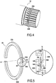
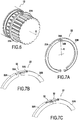
- the figures 4-5 and 6-7A respectively present a second and a third embodiment, fairly close to each other, of a connecting assembly.
- the second embodiment corresponds to the claimed invention, but not the third embodiment.
- the retaining means are formed by two hooks 34A and 34B, each being integrally formed. or in one piece in one end (first end) of one of the half-rings.
- the hooks 34A, 34B are made by making a notch 35A, 35B at the ends of the half-rings 22A, 22B.
- the notches 35A, 35B constitute hollows within the meaning of the present invention.
- Each of these hooks has the shape of a bent part (also denoted 34A, 34B), which extends from the first end of the half-ring in a direction perpendicular to the circumferential direction (according to the arrows X1, X2, on the Fig. 5 ).
- Each of these hooks or angled parts 34A, 34B comprises a retaining surface 36A, 36B whose outgoing perpendicular PA, PB is directed rearwardly with respect to the end direction (arrows A, B, Fig. 5 ) from the first end of the half-ring.
- This end direction is the circumferential direction at the first end of the considered half-ring, and more particularly in the outgoing direction with respect to this first end.
- the hooks 34A and 34B are shown engaged with each other.
- the surfaces 36A and 36B then face each other and their respective perpendicular directions are directed in the circumferential direction of the ring 22, parallel to the end directions A and B of the first ends of the rings, but in opposite directions.
- the main difference between the second and third embodiments lies in the orientation of the hooks 34A, 34B.
- the hooks 34A, 34B extend in the axial direction, that is to say the direction parallel to the X axis of the shaft (arrows X1, X2 parallel to the X axis, Fig. 5 ).
- the hooks 34A, 34B extend in a radial direction (radial direction R, Fig.7A ).
- the first ends of the half-rings are arranged such that to move these first ends from the mounted position to a position in which the first ends can move apart (in the circumferential direction), it is necessary to move the hook of one of the half-rings in the radial direction away from the shaft section 12.
- FIG. 6 A preferred embodiment of the method according to the invention is illustrated in particular by the figure 6 .
- the shaft section 12 is oriented horizontally.
- the half-rings 22A, 22B are then placed on either side of the shaft section, with their first ends arranged at the top, on the upper meridian of the shaft section.
- the weight of the half-rings keeps them in a stable position by preventing any radial centrifugal movement of their first ends which could allow them to disengage from one another.
- the second ends of the half rings i.e. the ends opposite to the first ends
- no retaining means is provided to prevent them from deviating from each other.
- the second ends are arranged identically to the first ends.
- the two half-rings 22A and 22B are identical. This embodiment assumes a certain flexibility of the half-rings in order to allow their installation.
- the half-rings are made of a very rigid material.
- FIGS. 7B and 7C show two arrangement possibilities of the retaining means according to the invention, when the half-rings are fairly rigid.
- the retaining means comprise a retaining part 32 rigidly fixed to the half-ring 22B.
- This retainer 32 is a small strip of elastic sheet metal.
- the first end 32B of this blade is fixed to the end of the half-ring 22B by welding.
- the second end is curved and has a bent portion 32A which extends in a re-entrant radial direction.
- the first end of the half-ring 22A for its part has a slot 33.
- the slot is arranged so that the bent part 32A of the retaining piece 32 can be inserted into the slot 33. In this position, the piece of retainer 32 prevents the first ends of the half-rings 22A and 22B from deviating from each other.
- Means to aid engagement such as a small chamfer in the direction of assembly can be provided.
- the blade length must be sufficient to allow bending with a force allowing the desired assembly, for example manually and without special tools.
- the elastic blade can for example be welded to the outside of the ring 22, in which case the diameter of the bore 24 of the host piece will be chosen to match the outside diameter of the ring at the location of the blades. .
- the bore 24 can retain the half-rings 22 at the location of the blades; or else, thinners can be provided on the half-rings 22a and 22B to accommodate the thickness of the blade, and the bore 24 of the receiving part can keep the half-rings in position over their entire periphery.
- the retaining means comprise two retaining pieces 32 rigidly fixed respectively to each of the half-rings 22A and 22B. These retainers are similar to the retainer 32 of the first variant. Each is also a small strip of elastic sheet metal. The free ends of these retainers each have a bent portion. These bent parts are curved: one radially outward (relative to the X axis) and the other radially inward.
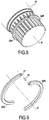
- the figures 8-9 and 10-11 respectively present a fourth and a fifth embodiment, fairly close to each other, of a connecting assembly.
- the fourth embodiment corresponds to the claimed invention, but not the fifth embodiment.
- the retaining means comprise a retaining part 40.
- This part 40 is distinct both from the shaft section and from the half-rings.
- it has the shape of a cylindrical pin 40, but other shapes are possible.
- the pin 40 constitutes a shearing member which enables the first ends of the half-rings to be joined to one another.
- the first ends of the half-rings 22A, 22B are arranged as follows.
- a flat surface is provided at the first end of each of these half-rings.
- the two flat surfaces thus arranged are arranged so as to be in contact with one another when the half-rings are in the mounted position, and so that in this position, their common perpendicular is perpendicular to the circumferential direction of the half rings.
- a bore 41 (constituting a hollow within the meaning of the invention) is drilled in each of these surfaces in the direction perpendicular to them. These bores are placed so as to be face to face in the mounted position of the half-rings and to allow the insertion of the pin 40.
- the pin 40 fixes the first ends of the two half-rings to one another and thus prevents them from deviating.
- the main difference between the fourth and fifth embodiments lies in the orientation of the pin 40 (and therefore the corresponding arrangement of the first ends of the half-rings):
- the pin In the fourth embodiment ( Fig. 8.9 ), the pin extends in a direction parallel to the X axis of the shaft ( Fig. 9 ); in the fifth embodiment ( Fig.10.11 ), it extends in the radial direction R.
- the second ends of the half-rings are free; conversely in the fifth embodiment, the second ends are arranged identically to the first ends, and the two half-rings 22A and 22B are identical.
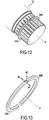
- the figures 12 and 13 illustrate a sixth embodiment.
- the retaining means also comprise a retaining part 40, separate from the shaft section and the half-rings, and having the shape of a cylindrical bar.
- planar surfaces are respectively provided at the first end of each of the half-rings 22A, 22B. They are arranged such that when the half-rings are in the mounted position, they are in contact with each other, and their common perpendicular is perpendicular to the circumferential direction at the first end of the half-rings.
- a semi-cylindrical groove (constituting a hollow within the meaning of the invention) is provided in each of these surfaces in the radial direction.
- the two grooves thus provided are placed so as to be face to face in the mounted position of the half-rings, and to be able to accommodate the bar 40.
- the half-rings are placed in the notches 26 of the grooves 20, between the axial stops 25.
- the axial stops 25 prevent an axial separation of the first ends of the half-rings in the axial direction (arrows X1 and X2, Fig.13 ). Therefore in this position of the ring, the two plane surfaces of the half-rings 22A, 22B remain in contact with each other.
- the bar 40 therefore remains in contact both with the groove formed in the half-ring 22A, and with the groove formed in the half-ring 22B. It thus prevents the first ends of the half-rings from moving away from one another in the circumferential direction.
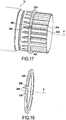
- the figures 14-16 and 17-18 respectively present a seventh and an eighth embodiment, fairly close to each other, of a connecting assembly according to the invention.
- the retaining means comprise two hooks 34A and 34B, each having an elbow portion (also 34A, 34B) integrated into the first end of each of the half-rings and extending in a direction perpendicular to the direction. circumferential.
- this direction is the radial direction (R), while in the eighth embodiment, this direction is the axial direction (X) of the shaft section.
- the first ends of the half-rings are prevented from moving away from each other by a retaining piece, namely in this case, the shaft section 12 itself.
- the shaft section has a radial hole 42 ( Fig.14.15 ), designed to receive the hooks 34A, 34B.
- the radial hole 42 is preferably placed substantially towards the top of the wheel spindle 12 when mounting the cylinder block on the spindle 12.
- the force of gravity is therefore exerted along the arrow G.
- the half-rings 22A and 22B shown on the figure 16 are placed on the wheel spindle 12 such that the hooks 24A and 34B engage in the hole 42 located at the top of the spindle 12.
- this assembly does not require any jamming of the parts, and therefore allows very easy manual or robotic positioning.
- the hooks 34A, 34B are formed in the axial direction and engaged between two ribs 20B, 20A of the splines 20 of the shaft section 12.
- the side walls of the ribs 20B, 20A constitute locking surfaces which prevent the first ends of the half rings to move away from each other.
- the first end of a first of the half-rings comprises a cylindrical rod 44 which extends in the circumferential direction in the extension of the body of the half-ring; the first end of the second half-ring conversely comprises a cylindrical bore 46 which extends, also in the circumferential direction, inside the body of the half-ring.
- the rod 44 has an outside diameter very slightly greater, or even equal (or even slightly less), to the inside diameter of the bore 46. Also, when the rod 44 is engaged in the bore 46, a certain friction occurs. between the rod 44 and the bore 46.
- the retaining means generally have to fulfill their function (prevent the first ends of the two half-rings from moving away from each other) only when the half-rings are assembled, and until they are capped or covered (at least in part) by the reception room.
- they may be formed from a rigid material (as for example in the first embodiment, Fig. 2 ), they can also be made at least partially of flexible material, and thus shaped only just before assembly. This may for example be the case with hooks 34A, 34B of the seventh and eighth embodiment, which can be made of a material which can be deformed by hand.
- the holding in position of the half-rings by the retaining means is carried out provisionally during the first step a) of the assembly.
- the retaining action provided by the retaining means may be relatively weak, that is to say just sufficient to prevent the rings from falling under the effect of their own weight.
- the holding in the final position of the half rings allowing them to perform their function of axially holding the host piece on the machine or the vehicle, is secured by the external axial covering of the half-rings by the reception piece.
- the half-rings cannot escape.
- the retaining means can therefore be considered as first retaining means, used initially on a temporary basis to allow the two half-rings to be maintained in the desired mounting position. ; and the connecting assembly is completed by second retaining means which are produced by the axial covering of the half rings by the receiving part in order to hold the half rings radially against the shaft section.
- connection assembly according to the invention is particularly advantageous for fitting the rockets with the wheels of machines, vehicles or trailers which use hydraulic motors. It is particularly advantageous for equipping the wheel spindles of these vehicles with hydraulic assistance motors, more particularly in the particular case of multilobe cam motors, with rotating cam connected to a hub and with a fixed cylinder block carried by the spindle. wheel.
- the linkage assembly facilitates the maintenance of hydraulic motors carried by wheel knuckles in a horizontal position, by allowing rapid assembly or disassembly of the stop ring. It advantageously applies to machines and vehicles equipped with temporary traction assistance with disengageable or declutchable cam motors by retraction of the pistons or by disengaging the cylinder block from the shaft. It advantageously applies to the steering wheel spindles of such machines or vehicles.
- this connecting assembly is advantageously applied to the mounting of hydraulic motors on the axles of machines or semi-finished vehicles in a horizontal position.
Description
L'invention concerne un ensemble de liaison comportant essentiellement une pièce d'accueil, un anneau d'arrêt constitué principalement par deux demi-anneaux, et un tronçon d'arbre prévu pour être placé dans un alésage de la pièce d'accueil. L'invention concerne également un procédé de montage d'un tel ensemble de liaison.The invention relates to a connecting assembly comprising essentially a receiving part, a stop ring consisting mainly of two half-rings, and a shaft section intended to be placed in a bore of the receiving part. The invention also relates to a method of mounting such a connection assembly.
Dans un tel ensemble de liaison, l'anneau d'arrêt a pour fonction de solidariser axialement le tronçon d'arbre par rapport à la pièce d'accueil, c'est-à-dire, d'empêcher leurs mouvements relatifs suivant la direction de l'axe du tronçon d'arbre (Dans le présent document, le terme 'axial' fait référence à la direction de l'axe du tronçon d'arbre).In such a connection assembly, the stop ring has the function of axially securing the shaft section relative to the host part, that is to say, to prevent their relative movements in the direction of the axis of the shaft section (In this document, the term 'axial' refers to the direction of the axis of the shaft section).
Pour assurer cette solidarisation axiale, l'anneau d'arrêt est placé autour du tronçon d'arbre dans une position dite 'position montée' ; il est alors bloqué axialement sur le tronçon d'arbre grâce à une pluralité de butées axiales contre lesquelles l'anneau est placé. Il suffit que l'anneau d'arrêt soit bloqué axialement dans une direction suivant l'axe du tronçon d'arbre. Cependant, de préférence l'anneau d'arrêt est bloqué par les butées axiales sur le tronçon d'arbre dans les deux directions.To ensure this axial connection, the stop ring is placed around the shaft section in a position called "mounted position"; it is then locked axially on the shaft section by virtue of a plurality of axial stops against which the ring is placed. It suffices for the stop ring to be axially blocked in a direction along the axis of the shaft section. However, preferably the stop ring is locked by the axial stops on the shaft section in both directions.
La pièce d'accueil comprend de manière similaire une ou plusieurs butées axiales aptes à solidariser axialement l'anneau par rapport à la pièce d'accueil, c'est-à-dire permettant d'empêcher un mouvement relatif de celui-ci au moins dans une direction suivant l'axe du tronçon d'arbre, par rapport à la pièce d'accueil.The receiving part similarly comprises one or more axial stops capable of axially securing the ring relative to the receiving part, that is to say making it possible to prevent relative movement of the latter at least. in a direction along the axis of the shaft section, relative to the host part.
Les butées axiales du tronçon d'arbre peuvent définir ou délimiter à la surface de celui-ci une gorge, éventuellement discontinue, dans laquelle l'anneau est placé. Dans ce cas, les parois latérales de la gorge constituent les butées axiales au sens indiqué précédemment. Cependant, il n'est pas nécessaire que l'anneau soit maintenu latéralement de manière continue. Il suffit qu'il existe un certain nombre de butées axiales, situées de part et d'autre de l'anneau, pour maintenir celui-ci axialement.The axial stops of the shaft section can define or delimit on the surface of the latter a groove, possibly discontinuous, in which the ring is placed. In this case, the side walls of the groove constitute the axial stops in the sense indicated above. However, it is not necessary for the ring to be held laterally continuously. It suffices that there are a certain number of axial stops, located on either side of the ring, to maintain the latter axially.
L'utilisation d'un anneau d'arrêt pour solidariser axialement un arbre et une pièce d'accueil dans laquelle il est engagé est une technique connue en soi.The use of a stop ring for axially securing a shaft and a receiving part in which it is engaged is a technique known per se.
En général, les anneaux d'arrêts sont constitués d'un anneau élastique que l'on enfile sur un arbre en l'écartant avec des pinces par déformation élastique, puis on relâche l'anneau qui se place dans une gorge. L'anneau tient en place de lui-même.In general, the stop rings consist of an elastic ring which is threaded on a shaft by removing it with pliers by elastic deformation, then the ring is released which is placed in a groove. The ring holds itself in place.
Pour le cas particulier de très forts efforts axiaux, ce qui est souvent le cas des moteurs hydrauliques, l'anneau doit être très massif et épais, on ne peut plus le déformer élastiquement, et il n'est plus possible de le poser avec des pinces. On préfère donc utiliser deux demi anneaux. Un tel anneau d'arrêt est par exemple divulgué par le document
Lors du montage de la pièce d'accueil sur le tronçon d'arbre, on dispose généralement le tronçon d'arbre suivant la direction verticale. On place alors les deux demi-anneaux dans la gorge (c'est-à-dire entre les butées axiales) prévue sur le tronçon d'arbre pour les recevoir.When mounting the reception piece on the shaft section, the shaft section is generally arranged in the vertical direction. The two half-rings are then placed in the groove (that is to say between the axial stops) provided on the shaft section to receive them.
Comme le tronçon d'arbre est orienté dans la direction verticale, chacun des demi-anneaux repose de manière stable sur celui-ci. Le montage de la pièce d'accueil sur le tronçon d'arbre peut donc se dérouler sans difficulté.Since the shaft section is oriented in the vertical direction, each of the half-rings rests stably on it. The assembly of the reception piece on the shaft section can therefore take place without difficulty.
Cependant, le montage de la pièce d'accueil sur le tronçon d'arbre est plus difficile lorsque le tronçon d'arbre est orienté suivant une direction horizontale. Ce cas survient notamment lorsque le tronçon d'arbre est une fusée de roue : dans ce cas en effet, il n'est pas possible d'orienter le tronçon d'arbre dans la direction verticale, et le montage doit être réalisé alors que le tronçon d'arbre est horizontal.However, the mounting of the reception piece on the shaft section is more difficult when the shaft section is oriented in a horizontal direction. This case occurs in particular when the shaft section is a wheel spindle: in this case, it is not possible to orient the shaft section in the vertical direction, and the assembly must be carried out while the tree section is horizontal.
Or dans cette configuration, lorsque les demi-anneaux sont placés dans la gorge du tronçon d'arbre, au moins l'un des deux a tendance à tomber.However, in this configuration, when the half-rings are placed in the groove of the shaft section, at least one of the two tends to fall.
Habituellement, pour remédier à ce problème on utilise divers artifices pour maintenir en place les demi anneaux pendant la phase montée : on maintient ceux-ci avec de la colle ou de la graisse ; ou on prévoit une gorge légèrement plus étroite que les demi-anneaux, ce qui permet de coincer ceux-ci en position pendant la phase montée. Mais ces solutions ne sont guère pratiques.Usually, to remedy this problem, various devices are used to keep the half-rings in place during the ascent phase: they are held with glue or grease; or a groove is provided which is slightly narrower than the half-rings, which makes it possible to clamp the latter in position during the ascent phase. But these solutions are hardly practical.
Il existe donc un besoin pour un ensemble de liaison comportant une pièce d'accueil, un tronçon d'arbre et un anneau d'arrêt associés, et dans lequel la pièce d'accueil puisse être montée de manière simple, sans nécessiter le collage de l'anneau d'arrêt sur le tronçon d'arbre.There is therefore a need for a connecting assembly comprising a receiving part, a shaft section and an associated stop ring, and in which the reception piece can be mounted in a simple manner, without requiring the gluing of the stop ring on the shaft section.
Par ailleurs, lorsque l'anneau d'arrêt est composé de deux demi-anneaux et qu'il est mis en rotation ses demi-anneaux sont soumis à des forces centrifuges.Furthermore, when the stop ring is composed of two half-rings and it is rotated, its half-rings are subjected to centrifugal forces.
D'autre part, même dans les cas où inversement l'anneau est monté sur un tronçon d'arbre non rotatif, comme par exemple une fusée de roue non rotative, même en l'absence de force centrifuge, il peut être indispensable que les demi anneaux ne puissent se déplacer sous l'effet des chocs ou des vibrations pendant l'exploitation.On the other hand, even in cases where, conversely, the ring is mounted on a non-rotating shaft section, such as for example a non-rotating wheel spindle, even in the absence of centrifugal force, it may be essential that the half rings cannot move under the effect of shocks or vibrations during operation.
Aussi, afin de maintenir la position relative des deux demi-anneaux l'un par rapport à l'autre, de manière connue l'anneau peut comporter des moyens de retenue servant à maintenir les deux demi-anneaux en position relative fixe l'un par rapport à l'autre. De tels moyens de retenue sont par exemple proposés par le document
Comme ces moyens de retenue sont indispensables pour assurer le maintien en position de l'anneau pendant toute la durée d'exploitation, ils doivent être dimensionnés de manière à avoir une fiabilité très élevée, analogue à celle des demi-anneaux. Il s'ensuit un coût non négligeable pour assurer cette fonction de maintien en position de l'anneau durant l'exploitation.As these retaining means are essential to ensure that the ring is held in position throughout the operating period, they must be dimensioned so as to have very high reliability, similar to that of the half-rings. It follows a non-negligible cost to ensure this function of maintaining the ring in position during operation.
Un premier objectif de l'invention est de remédier aux inconvénients indiqués précédemment et de proposer un ensemble de liaison tel que présenté en introduction, dont le montage soit plus simple que les ensembles de liaison antérieurs.A first objective of the invention is to remedy the drawbacks indicated above and to provide a connection assembly as presented in the introduction, the assembly of which is simpler than the previous connection assemblies.
Un deuxième objectif de l'invention est de proposer un ensemble de liaison tel que présenté en introduction, comportant des moyens de retenue servant à maintenir les deux demi-anneaux en position durant la phase d'exploitation, permettant une phase de montage facile, et de coût inférieur aux ensembles de liaison connus.A second objective of the invention is to provide a connecting assembly as presented in the introduction, comprising retaining means serving to keep the two half-rings in position during the operating phase, allowing an easy assembly phase, and of lower cost than known link assemblies.
Dans ce but selon l'invention, il est proposé un ensemble de liaison comprenant une pièce d'accueil, un anneau d'arrêt, et un tronçon d'arbre présentant une pluralité de butées axiales aptes à empêcher un déplacement axial de l'anneau lorsque celui-ci est disposé autour dudit tronçon ; la pièce d'accueil présentant un alésage pour recevoir le tronçon d'arbre ;
l'anneau étant constitué principalement par deux demi-anneaux déplaçables l'un par rapport à l'autre, chaque demi-anneau présentant une première extrémité et une deuxième extrémité ;
l'ensemble de liaison comportant des moyens de retenue aptes, lorsque l'anneau est placé dans une position montée autour dudit tronçon et retenu axialement par lesdites butées axiales, à empêcher la première extrémité d'un premier desdits demi-anneaux et la première extrémité du deuxième desdits demi-anneaux de s'écarter l'une de l'autre suivant une direction circonférentielle ;
l'anneau empêchant en position montée un déplacement relatif suivant une direction axiale du tronçon d'arbre par rapport à la pièce d'accueil.For this purpose according to the invention, there is provided a connecting assembly comprising a receiving part, a stop ring, and a shaft section having a plurality of axial stops capable of preventing axial displacement of the ring. when the latter is arranged around said section; the receiving part having a bore to receive the shaft section;
the ring being formed mainly by two half-rings which can be moved relative to one another, each half-ring having a first end and a second end;
the connection assembly comprising retaining means capable, when the ring is placed in a position mounted around said section and retained axially by said axial stops, to prevent the first end of a first of said half-rings and the first end the second of said half-rings to move away from each other in a circumferential direction;
the ring preventing in the mounted position a relative movement in an axial direction of the shaft section relative to the receiving part.
L'ensemble de liaison est de plus agencé de telle sorte qu'en position montée, l'anneau est interposé entre le tronçon d'arbre et la pièce d'accueil et est maintenu radialement contre le tronçon d'arbre par la pièce d'accueil ; en outre, les moyens de retenue sont agencés pour le maintien des premières extrémités des demi-anneaux, tandis que les deuxièmes extrémités sont libres.The connecting assembly is further arranged such that, in the mounted position, the ring is interposed between the shaft section and the host part and is held radially against the shaft section by the part of Home ; furthermore, the retaining means are arranged to hold the first ends of the half-rings, while the second ends are free.
La direction circonférentielle considérée ici est la direction circonférentielle sur la circonférence du tronçon d'arbre, entre les premières extrémités des demi-anneaux ou au niveau de celles-ci.The circumferential direction considered here is the circumferential direction on the circumference of the shaft section, between the first ends of the half-rings or at the level thereof.
Dans certains modes de réalisation, lors du montage des demi-anneaux sur le tronçon d'arbre, si celui-ci est orienté suivant une direction horizontale, les demi-anneaux peuvent être disposés de part et d'autre du tronçon d'arbre, de telle sorte que leurs premières extrémités réunies constituent le point haut de l'anneau placé en position montée sur l'arbre.In certain embodiments, when the half-rings are mounted on the shaft section, if the latter is oriented in a horizontal direction, the half-rings can be placed on either side of the shaft section, so that their first joined ends constitute the high point of the ring placed in position mounted on the shaft.
Dans cette position, grâce aux moyens de retenue empêchant les deux premières extrémités des demi-anneaux de s'écarter suivant la direction circonférentielle, les deux demi-anneaux se soutiennent mutuellement (plutôt que de tomber de part et d'autre du tronçon d'arbre), si bien que l'anneau reste en position montée sur le tronçon d'arbre. Le montage de la pièce d'accueil peut donc alors être réalisé sans difficultés.In this position, thanks to the retaining means preventing the first two ends of the half-rings from moving away in the circumferential direction, the two half-rings support each other (rather than falling on either side of the section of shaft), so that the ring remains in the mounted position on the shaft section. The assembly of the reception room can therefore be carried out without difficulty.
De plus grâce à l'invention, les demi-anneaux peuvent être montés sans serrage entre les butées axiales du tronçon d'arbre. Avantageusement, cela évite qu'ils ne soient montés sur le tronçon d'arbre de manière trop rigide, ou qu'ils soient soumis inutilement à des contraintes. Cela facilite également le montage.Furthermore, thanks to the invention, the half-rings can be mounted without clamping between the axial stops of the shaft section. Advantageously, this prevents them from being mounted on the shaft section too rigidly, or that they are subjected to unnecessary stress. This also facilitates assembly.
Ainsi dans un mode de réalisation, les demi-anneaux sont montés entre les butées axiales avec un jeu axial par rapport à celles-ci.Thus in one embodiment, the half-rings are mounted between the axial stops with an axial play relative to the latter.
Cependant ils peuvent également être montés avec un léger serrage entre les butées axiales.However, they can also be mounted with a slight clamping between the axial stops.
Les demi-anneaux s'étendent habituellement sur 360° autour de l'arbre. Ils peuvent cependant éventuellement s'étendre sur une plage angulaire strictement inférieure à 360°, par exemple 330°.The half rings usually extend 360 ° around the tree. However, they may optionally extend over an angular range strictly less than 360 °, for example 330 °.
Les butées axiales peuvent être formées de manière intégrale (monobloc) avec le tronçon d'arbre. Cependant, elles peuvent également être formées par des pièces distinctes du tronçon d'arbre, et fixées ou rapportées sur celui-ci.The axial stops can be formed integrally (in one piece) with the shaft section. However, they can also be formed by separate parts of the shaft section, and fixed or attached to it.
Chaque butée axiale doit avoir une liaison avec le tronçon d'arbre qui au moins empêche la butée axiale de se déplacer par rapport au tronçon d'arbre dans le sens qui augmenterait la possibilité de déplacement axial de l'anneau sur le tronçon d'arbre. Cela dit, en général chaque butée axiale est rigidement fixée au tronçon d'arbre.Each axial stop must have a connection with the shaft section which at least prevents the axial stop from moving relative to the shaft section in the direction which would increase the possibility of axial displacement of the ring on the shaft section . However, in general each axial stop is rigidly fixed to the shaft section.
La pièce d'accueil peut notamment être un bloc-cylindres de moteur hydraulique, notamment un moteur hydraulique à pistons radiaux.The receiving part may in particular be a hydraulic motor cylinder block, in particular a radial piston hydraulic motor.
Le tronçon d'arbre peut être un tronçon d'arbre de sortie de moteur et/ou une fusée de roue.The shaft section may be an engine output shaft section and / or a wheel spindle.
De nombreux modes de réalisation sont envisageables pour les moyens de retenue.Many embodiments are conceivable for the retaining means.
Dans un mode de réalisation non couvert par les revendications annexées, les moyens de retenue comportent un bracelet élastique apte à coopérer avec les demi-anneaux de manière à maintenir ceux-ci au contact du tronçon d'arbre, en position montée. Grâce à ce bracelet, les deux demi-anneaux sont maintenus dans une position fixe au contact de la surface extérieure du tronçon d'arbre, entre les butées axiales. Par suite, leurs premières extrémités sont empêchées de s'écarter.In an embodiment not covered by the appended claims, the retaining means comprise an elastic strap able to cooperate with the half-rings so as to keep the latter in contact with the shaft section, in the mounted position. Thanks to this strap, the two half-rings are held in a fixed position in contact with the outer surface of the shaft section, between the axial stops. As a result, their first ends are prevented from deviating.
Dans un mode de réalisation, les premières extrémités des demi-anneaux peuvent comporter une partie coudée qui s'étend suivant une direction radiale. Cette partie coudée peut également s'étendre suivant une direction parallèle à un axe de l'arbre.In one embodiment, the first ends of the half-rings may include a bent portion which extends in a radial direction. This bent part can also extend in a direction parallel to an axis of the shaft.
Ces parties coudées forment des crochets qui coopèrent l'un avec l'autre, directement ou indirectement, pour empêcher les premières extrémités des demi-anneaux de s'écarter.These bent parts form hooks which cooperate with one another, directly or indirectly, to prevent the first ends of the half-rings from moving apart.
Dans un mode de réalisation, les moyens de retenue comportent une pièce de retenue fixée rigidement à l'un des demi-anneaux. Dans le cas où les premières extrémités des demi-anneaux comportent une partie coudée, au moins l'une de ces parties coudées peut être constituée par cette pièce de retenue.In one embodiment, the retaining means comprise a retaining part rigidly fixed to one of the half-rings. In the case where the first ends of the half-rings have a bent part, at least one of these bent parts can be formed by this retaining part.
Inversement, dans un mode de réalisation les moyens de retenue sont constitués d'une part par une partie intégrale d'un premier desdits demi-anneaux, et d'autre part par une partie intégrale de l'autre desdits demi-anneaux. L'expression 'partie intégrale' signifie ici que la portion considérée des moyens de retenue est formée de manière intégrale, ou monobloc, avec le demi-anneau considéré.Conversely, in one embodiment, the retaining means are formed on the one hand by an integral part of a first of said half-rings, and on the other hand by an integral part of the other of said half-rings. The expression “integral part” here means that the considered portion of the retaining means is formed integrally, or in one piece, with the considered half-ring.
Dans un mode de réalisation, les moyens de retenue sont agencés de telle sorte que tout déplacement relatif des premières extrémités des demi-anneaux, depuis la position montée jusqu'à une position dans laquelle l'écartement desdites premières extrémités suivant la direction circonférentielle est possible, comporte ou implique un déplacement radial d'au moins une des premières extrémités.In one embodiment, the retaining means are arranged such that any relative displacement of the first ends of the half-rings, from the mounted position to a position in which the separation of said first ends in the circumferential direction is possible , includes or involves a radial displacement of at least one of the first ends.
Cela peut être réalisé par exemple en agençant les butées axiales du tronçon d'arbre de manière à empêcher tout écartement axial des premières extrémités.This can be done for example by arranging the axial stops of the shaft section so as to prevent any axial separation of the first ends.
Ainsi, pour que les premières extrémités s'écartent l'une de l'autre, au moins l'une d'elles doit d'abord se déplacer radialement (dans le sens centrifuge, en s'écartant du tronçon d'arbre).Thus, for the first ends to move away from each other, at least one of them must first move radially (in the centrifugal direction, away from the shaft section).
Or, lorsque le tronçon d'arbre est orienté horizontalement avec les premières extrémités placées sur la méridienne supérieure, ce déplacement radial centrifuge se produit vers le haut. Ce déplacement nécessite donc que la première extrémité de demi-anneau considérée se soulève, c'est-à-dire se déplace vers le haut. Ce déplacement est donc empêché par la gravité.However, when the shaft section is oriented horizontally with the first ends placed on the upper meridian, this centrifugal radial displacement occurs upwards. This movement therefore requires that the first end of the half-ring considered to rise, that is to say to move upwards. This movement is therefore prevented by gravity.
Par suite dans ce mode de réalisation, grâce la gravité, avantageusement chacune des premières extrémités est empêchée de se désengager et/ou de s'écarter de la première extrémité de l'autre demi-anneau.Consequently in this embodiment, thanks to gravity, each of the first ends is advantageously prevented from disengaging and / or from moving away from the first end of the other half-ring.
Plus précisément en position montée, du fait de la position des centres de gravité des demi-anneaux par rapport au tronçon d'arbre, la première extrémité de chacun des demi-anneaux se plaque contre le tronçon d'arbre : position dans laquelle les premières extrémités des demi-anneaux sont empêchées de s'écarter l'une de l'autre.More precisely in the mounted position, due to the position of the centers of gravity of the half-rings relative to the shaft section, the first end of each of the half-rings is pressed against the shaft section: position in which the first ends of the half-rings are prevented from deviating from each other.
Dans un mode de réalisation, la première extrémité de chacun des demi-anneaux comporte une surface de retenue dont la perpendiculaire sortante est dirigée vers l'arrière par rapport à la direction de la première extrémité du demi-anneau ; les surfaces de retenue des deux demi-anneaux sont agencées de manière à pouvoir être placées dans une position d'engagement l'une avec l'autre, dans laquelle i'écartement des premières extrémités des demi-anneaux est empêché.In one embodiment, the first end of each of the half-rings comprises a retaining surface, the outgoing perpendicular of which is directed rearwardly with respect to the direction of the first end of the half-ring; the retaining surfaces of the two half-rings are arranged so as to be able to be placed in a position of engagement with each other, in which the separation of the first ends of the half-rings is prevented.
Chacune des surfaces de retenue forme ainsi une sorte de crochet, ou encore agit comme un crochet, et coopère directement ou indirectement avec l'autre surface de retenue pour empêcher les deux premières extrémités des deux demi-anneaux de s'écarter suivant la direction circonférentielle (du tronçon d'arbre).Each of the retaining surfaces thus forms a kind of hook, or else acts as a hook, and cooperates directly or indirectly with the other retaining surface to prevent the first two ends of the two half-rings from moving away in the circumferential direction. (of the tree section).
L'orientation des surfaces de retenue, dont les perpendiculaires sortantes sont orientées vers l'arrière par rapport à la direction des premières extrémités des demi-anneaux, permet que la fonction anti-écartement des moyens de retenue soit réalisée sans recours à des moyens de retenue compliqués comme le collage.The orientation of the retaining surfaces, the outgoing perpendiculars of which are oriented towards the rear relative to the direction of the first ends of the half-rings, allows the anti-separation function of the retaining means to be performed without recourse to means of complicated retainers like gluing.
Dans un mode de réalisation, les surfaces de retenue sont aptes à être engagées directement l'une avec l'autre de manière à empêcher lesdites premières extrémités de s'écarter l'une de l'autre suivant la direction circonférentielle, ou bien à les maintenir à une distance constante l'une de l'autre, lorsque l'anneau est en position montée. Le terme 'directement' signifie que les surfaces de retenue sont alors en contact l'une avec l'autre.In one embodiment, the retaining surfaces are suitable for being directly engaged with one another so as to prevent said first ends from moving away from each other in the circumferential direction, or else to prevent them. keep a constant distance from each other when the ring is in the mounted position. The term 'directly' means that the retaining surfaces are then in contact with each other.
Dans un mode de réalisation, au moins l'un des demi-anneaux comporte un creux suivant une direction sensiblement perpendiculaire à la direction circonférentielle ; les moyens de retenue comportent au moins une saillie apte à être placée dans ledit creux, et la saillie est solidaire de l'autre demi-anneau quant aux déplacements suivant la direction circonférentielle.In one embodiment, at least one of the half-rings comprises a hollow in a direction substantially perpendicular to the circumferential direction; the retaining means comprise at least one projection suitable for being placed in said hollow, and the projection is integral with the other half-ring as regards the displacements in the circumferential direction.
On comprend que le creux a une forme qui permet de retenir la saillie et d'empêcher celle-ci de se déplacer suivant la direction circonférentielle du tronçon d'arbre, au moins dans le sens qui permet l'écartement des deux premières extrémités des demi-anneaux, suivant la direction circonférentielle. Par suite, l'engagement de la saillie dans le creux empêche l'écartement relatif des premières extrémités des deux demi-anneaux.It is understood that the hollow has a shape which makes it possible to retain the projection and to prevent the latter from moving in the circumferential direction of the shaft section, at least in the direction which allows the separation of the first two ends of the halves. -rings, following the circumferential direction. Consequently, the engagement of the projection in the hollow prevents the relative separation of the first ends of the two half-rings.
Le creux peut avoir différentes formes : il peut être un trou cylindrique (de préférence, mais pas nécessairement, d'axe s'étendant dans un plan perpendiculaire à la direction circonférentielle ; un axe orienté suivant la direction circonférentielle peut même convenir), la saillie ayant alors une forme lui permettant d'être engagée dans le trou cylindrique.The hollow can have different shapes: it can be a cylindrical hole (preferably, but not necessarily, with an axis extending in a plane perpendicular to the circumferential direction; an axis oriented in the circumferential direction may even be suitable), the projection then having a shape allowing it to be engaged in the cylindrical hole.
Le creux peut également être semi-cylindrique (le plan du demi-cylindre étant un plan méridien) ou hémisphérique, et la saillie a une forme permettant d'être engagée dans ledit trou, et les premières extrémités sont empêchées de s'écarter l'une de l'autre suivant une direction perpendiculaire à la direction d'engagement de la saillie dans ledit creux.The hollow may also be semi-cylindrical (the plane of the half-cylinder being a meridian plane) or hemispherical, and the protrusion has a shape allowing it to be engaged in said hole, and the first ends are prevented from deviating from the hole. one from the other in a direction perpendicular to the direction of engagement of the projection in said hollow.
Plus généralement toutes les formes aménagées sur les premières extrémités respectives des deux demi-anneaux, et qui sont aptes à coopérer l'une avec l'autre pour empêcher l'écartement relatif, suivant la direction circonférentielle, des premières extrémités des demi-anneaux, peuvent être utilisées.More generally all the shapes arranged on the respective first ends of the two half-rings, and which are able to cooperate with one another to prevent the relative separation, in the circumferential direction, of the first ends of the half-rings, can be used.
Dans un mode de réalisation, les moyens de retenue comportent une pièce de retenue déplaçable par rapport aux demi-anneaux ; et la pièce de retenue est apte à être placée au contact des surfaces de retenue de manière à transmettre un effort s'exerçant entre celles-ci et par suite à empêcher l'écartement desdites premières extrémités l'une par rapport à l'autre.In one embodiment, the retaining means comprise a retaining part which can be moved relative to the half-rings; and the retaining part is suitable for being placed in contact with the retaining surfaces so as to transmit a force exerted between them and consequently to prevent the separation of said first ends from one another.
La pièce de retenue peut notamment être une goupille, un cylindre, une bille : Elle est en fait généralement un organe de cisaillement, c'est-à-dire une pièce transmettant des contraintes notamment de cisaillement d'une pièce à une autre, en l'occurrence, de l'un à l'autre des demi-anneaux.The retaining part can in particular be a pin, a cylinder, a ball: It is in fact generally a shearing member, that is to say a part transmitting stresses in particular shearing stresses from one part to another, by the occurrence, from one to the other of the half-rings.
Lorsque les moyens de retenue comportent une saillie placée dans un trou pour empêcher l'écartement des premières extrémités des demi-anneaux, la saillie indiquée précédemment peut être solidaire de l'un des demi-anneaux, et par exemple être formée de manière intégrale avec celui-ci.When the retaining means comprise a projection placed in a hole to prevent the separation of the first ends of the half-rings, the projection indicated above may be integral with one of the half-rings, and for example be formed integrally with this one.
Cependant, la saillie peut également faire partie d'une pièce de retenue telle qu'indiquée précédemment. Dans ce cas, la pièce de retenue doit être apte à être solidarisée au moins suivant la direction circonférentielle avec l'un des demi-anneaux (celui qui ne comporte pas le creux).However, the protrusion can also form part of a retainer as indicated above. In this case, the retaining part must be able to be secured at least in the circumferential direction with one of the half-rings (the one which does not include the hollow).
La pièce de retenue peut dans ce but par exemple comporter deux saillies, chacune des saillies étant prévue pour être placée dans un creux de l'un des demi-anneaux. La pièce de retenue peut par exemple être une goupille passant dans des trous du premier et du deuxième demi-anneau.For this purpose, the retaining piece may for example comprise two projections, each of the projections being designed to be placed in a hollow of one of the half-rings. The retaining piece may for example be a pin passing through holes in the first and second half-rings.
Dans un mode de réalisation, la pièce de retenue est le tronçon d'arbre lui-même.In one embodiment, the retainer is the shaft section itself.
Dans ce cas, le tronçon d'arbre peut présenter un ou deux trous, et les premières extrémités des demi-anneaux peuvent présenter des saillies aptes à être insérées dans le(s)dit(s) trou(s).In this case, the shaft section can have one or two holes, and the first ends of the half-rings can have projections suitable for being inserted into the said hole (s).
Il peut aussi être aménagé simplement avec deux surfaces de blocage, chacune de celles-ci servant à empêcher le déplacement l'une des premières extrémités des demi-anneaux suivant la direction circonférentielle dans le sens qui tend à faire s'écarter les premières extrémités des demi-anneaux.It can also be arranged simply with two locking surfaces, each of these serving to prevent the displacement of one of the first ends of the half-rings in the circumferential direction in the direction which tends to cause the first ends of the rings to move away. half rings.
Dans un mode de réalisation, les moyens de retenue comportent un aimant solidaire ou apte à être solidarisé avec l'un des demi-anneaux, et l'autre demi-anneau présente une extrémité ferromagnétique ou les moyens de retenue comportent une pièce ferromagnétique susceptible d'être fixée à l'extrémité de l'autre demi-anneau.In one embodiment, the retaining means comprise a magnet integral with or capable of being secured with one of the half-rings, and the other half-ring has a ferromagnetic end or the retaining means comprise a ferromagnetic part capable of 'be attached to the end of the other half-ring.
Dans un mode de réalisation, les deux demi-anneaux et le cas échéant la pièce de retenue sont aptes à être fixés les uns aux autres même en l'absence du tronçon d'arbre. La fixation peut se limiter à une fixation qui empêche les premières extrémités des deux demi-anneaux de s'écarter suivant la direction circonférentielle.In one embodiment, the two half-rings and, where appropriate, the retaining part are able to be fixed to each other even in the absence of the shaft section. The fixing may be limited to a fixing which prevents the first ends of the two half-rings from deviating in the circumferential direction.
Dans un mode de réalisation, les moyens de retenue sont distincts ou indépendants du tronc d'arbre.In one embodiment, the retaining means are separate or independent from the tree trunk.
Dans un mode de réalisation, les deux demi-anneaux sont identiques ou symétriques.In one embodiment, the two half-rings are identical or symmetrical.
Un troisième objectif de l'invention est de proposer un procédé de montage d'un ensemble de liaison du type présenté en introduction, qui soit simple, permette notamment d'éviter l'application de colle pour maintenir l'anneau sur le tronçon d'arbre, et qui nécessite un ensemble de maintien peu coûteux.A third objective of the invention is to provide a method of mounting a connecting assembly of the type presented in the introduction, which is simple, makes it possible in particular to avoid the application of glue to hold the ring on the section of shaft, and which requires an inexpensive holding assembly.
Cet objectif est atteint selon l'invention par un procédé de montage d'un ensemble de liaison tel que défini précédemment et comprenant les étapes suivantes :
- a) on place les deux demi-anneaux sur le tronçon d'arbre, en mettant en œuvre les moyens de retenue de telle sorte que la première extrémité d'un premier desdits demi-anneaux et la première extrémité du deuxième desdits demi-anneaux ne puissent s'écarter l'une de l'autre suivant une direction circonférentielle, les deuxièmes extrémités desdits demi-anneaux restant libres ;
- b) on engage la pièce d'accueil sur le tronçon d'arbre de telle sorte que le tronçon d'arbre soit disposé dans l'alésage de la pièce d'accueil, l'anneau étant interposé entre le tronçon d'arbre et la pièce d'accueil, et que la pièce d'accueil maintienne l'anneau radialement contre le tronçon d'arbre.
- a) the two half-rings are placed on the shaft section, implementing the retaining means so that the first end of a first of said half-rings and the first end of the second of said half-rings does not can move away from one another in a circumferential direction, the second ends of said half-rings remaining free;
- b) the host piece is engaged on the shaft section such that the shaft section is disposed in the bore of the host piece, the ring being interposed between the shaft section and the reception piece, and that the reception piece maintains the ring radially against the shaft section.
Avantageusement, dans le procédé de montage selon l'invention, le tronçon d'arbre peut être orienté horizontalement durant les étapes a) et b). Pendant ces étapes, les demi-anneaux sont maintenus en position grâce aux moyens de retenue.Advantageously, in the assembly method according to the invention, the shaft section can be oriented horizontally during steps a) and b). During these steps, the half-rings are held in position thanks to the retaining means.
Dans un mode préféré de mise en œuvre, lors de l'étape a) les premières extrémités des demi-anneaux sont disposées sur la méridienne supérieure du tronçon d'arbre. Cette disposition suffit pour que durant les étapes a) et b), les deux demi-anneaux restent en position sur le tronçon d'arbre, sans qu'il soit nécessaire de prévoir des moyens de maintien complémentaires.In a preferred embodiment, during step a) the first ends of the half-rings are arranged on the upper meridian of the shaft section. This arrangement is sufficient so that during steps a) and b), the two half-rings remain in position on the shaft section, without it being necessary to provide additional holding means.
L'invention sera bien comprise et ses avantages apparaîtront mieux à la lecture de la description détaillée qui suit, de modes de réalisation représentés à titre d'exemples non limitatifs. La description se réfère aux dessins annexés, sur lesquels :
- les
figures 1A, 1B et1C sont des vues schématiques en coupe des étapes d'un mode de mise en œuvre du procédé de montage d'un ensemble de liaison selon l'invention. - la
figure 2 est vue schématique en perspective d'un tronçon d'arbre de type connu. - la
figure 3 est une vue schématique en perspective d'un ensemble de liaison, dans un mode de réalisation qui ne correspond pas à l'invention revendiquée. - la
figure 4 est une vue schématique en perspective d'un ensemble de liaison, dans un deuxième mode de réalisation qui correspond à l'invention revendiquée. - la
figure 5 est une vue en perspective de l'anneau faisant partie de l'ensemble de liaison représenté sur lafigure 4 . - la
figure 6 est une vue schématique en perspective d'un ensemble de liaison dans un troisième mode de réalisation, qui ne correspond pas à l'invention revendiquée. - la
figure 7A est une vue en perspective de l'anneau faisant partie de l'ensemble de liaison représenté sur lafigure 6 . - les
figures 7B et 7C sont des vues schématiques d'un détail d'un anneau d'un ensemble de liaison similaire à l'anneau représenté sur lafigure 7A . - la
figure 8 est une vue schématique en perspective d'un ensemble de liaison, dans un quatrième mode de réalisation qui correspond à l'invention revendiquée. - la
figure 9 est une vue en perspective de l'anneau faisant partie de l'ensemble de liaison représenté sur lafigure 8 - la
figure 10 est une vue schématique en perspective d'un ensemble de liaison, dans un cinquième mode de réalisation qui ne correspond pas à l'invention revendiquée. - la
figure 11 est une vue en perspective de l'anneau faisant partie de l'ensemble de liaison représenté sur lafigure 10 . - la
figure 12 est une vue schématique en perspective d'un ensemble de liaison, dans un sixième mode de réalisation qui correspond à l'invention revendiquée. - la
figure 13 est une vue en perspective de l'anneau faisant partie de l'ensemble de liaison représenté sur lafigure 12 . - la
figure 14 est une vue schématique en perspective, en coupe partielle, d'un ensemble de liaison, dans un septième mode de réalisation qui correspond à l'invention revendiquée. - la
figure 15 est vue schématique en perspective du tronçon d'arbre faisant partie de l'ensemble de liaison représenté sur lafigure 14 . - la
figure 16 est une vue en perspective de l'anneau faisant partie de l'ensemble de liaison représenté sur lafigure 14 . - la
figure 17 est une vue schématique en perspective d'un ensemble de liaison, dans un huitième mode de réalisation qui correspond à l'invention revendiquée. - la
figure 18 est une vue en perspective de l'anneau faisant partie de l'ensemble de liaison représenté sur lafigure 17 . - la
figure 19 est une vue schématique en perspective, en coupe partielle, d'un ensemble de liaison, dans un neuvième mode de réalisation qui ne correspond pas à l'invention revendiquée, représenté en éclaté. - la
figure 20 est une vue en perspective de l'anneau faisant partie de l'ensemble de liaison représenté sur lafigure 19 .
- the
figures 1A, 1B and1 C are schematic sectional views of the steps of an embodiment of the method for mounting a connecting assembly according to the invention. - the
figure 2 is a schematic perspective view of a shaft section of known type. - the
figure 3 is a schematic perspective view of a link assembly, in an embodiment which does not correspond to the claimed invention. - the
figure 4 is a schematic perspective view of a link assembly, in a second embodiment which corresponds to the claimed invention. - the
figure 5 is a perspective view of the ring forming part of the link assembly shown infigure 4 . - the
figure 6 is a schematic perspective view of a link assembly in a third embodiment, which does not correspond to the claimed invention. - the
figure 7A is a perspective view of the ring forming part of the link assembly shown infigure 6 . - the
figures 7B and 7C are schematic views of a detail of a ring of a connecting assembly similar to the ring shown in Figurefigure 7A . - the
figure 8 is a schematic perspective view of a link assembly, in a fourth embodiment which corresponds to the claimed invention. - the
figure 9 is a perspective view of the ring forming part of the link assembly shown infigure 8 - the
figure 10 is a schematic perspective view of a link assembly, in a fifth embodiment which does not correspond to the claimed invention. - the
figure 11 is a perspective view of the ring forming part of the link assembly shown infigure 10 . - the
figure 12 is a schematic perspective view of a link assembly, in a sixth embodiment which corresponds to the claimed invention. - the
figure 13 is a perspective view of the ring forming part of the link assembly shown infigure 12 . - the
figure 14 is a schematic perspective view, in partial section, of a connecting assembly, in a seventh embodiment which corresponds to the claimed invention. - the
figure 15 is a schematic perspective view of the shaft section forming part of the connection assembly shown infigure 14 . - the
figure 16 is a perspective view of the ring forming part of the link assembly shown infigure 14 . - the
figure 17 is a schematic perspective view of a link assembly, in an eighth embodiment which corresponds to the claimed invention. - the
figure 18 is a perspective view of the ring forming part of the link assembly shown infigure 17 . - the
figure 19 is a schematic perspective view, in partial section, of a connecting assembly, in a ninth embodiment which does not correspond to the claimed invention, shown in exploded view. - the
figure 20 is a perspective view of the ring forming part of the link assembly shown infigure 19 .
Différents modes de réalisation d'ensembles de liaison vont maintenant être présentés en relation avec les
Dans les différents modes de réalisation, les éléments correspondants ou identiques portent un même signe de référence et ne sont décrits que pour le premier mode de réalisation dans lequel ils apparaissent.In the various embodiments, the corresponding or identical elements bear the same reference sign and are only described for the first embodiment in which they appear.
La
Le moteur hydraulique 10 est un moteur hydraulique à pistons radiaux de type connu en soi. Il comporte notamment un bloc-cylindres 14 monté sur la fusée 12. La fusée 12 constitue un tronçon d'arbre au sens de l'invention.The
Le bloc-cylindres 14 est traversé de part en part par un alésage 16, sur lequel sont usinées des cannelures longitudinales 18.The
La surface extérieure de la fusée 12 est formée, quant à elle, avec des cannelures longitudinales 20.The outer surface of the
Lorsque la fusée 12 est positionnée dans l'alésage 16, les cannelures 18 sont engagées avec les cannelures 20. Le bloc-cylindres 14 est alors solidarisé en grande partie avec la fusée 12 ; cependant, la coopération entre les cannelures 18 et 20 laisse libre un degré de liberté, à savoir celui qui concerne la translation relative du bloc-cylindres 14 par rapport à la fusée 12 suivant l'axe X de celle-ci.When the
Pour empêcher une telle translation et bloquer axialement le bloc-cylindres 14, un anneau d'arrêt 22 est prévu sur la fusée 12. L'ensemble comprenant le bloc-cylindres 14, la fusée 12 et l'anneau 22 constitue un ensemble de liaison, dont le bloc-cylindres 14 constitue la pièce d'accueil, au sens de l'invention.To prevent such translation and axially block the
L'anneau 22 est bloqué axialement sur la fusée 12 dans les deux directions suivant l'axe X de la fusée. Dans ce but, chacune des cannelures 20 présente une encoche 26 (
Les extrémités 25 des cannelures 20 au niveau des encoches 26 forment alors des butées axiales au sens de l'invention, qui empêchent l'anneau 22 de se déplacer axialement sur le tronçon d'arbre.The ends 25 of the
L'anneau 22 est constitué de deux demi-anneaux 22A et 22B qui seront détaillés par la suite.The
La position montée de l'ensemble de liaison est illustrée par la
Dans ce but, à l'extrémité de l'alésage 16 du bloc-cylindres 14 est formé un alésage 24 de plus grand diamètre que l'alésage 16. L'alésage 24 est prévu pour recevoir l'anneau 22 avec un jeu qui doit être strictement inférieur et de préférence nettement inférieur à l'épaisseur de l'anneau 22, c'est-à-dire à la différence de rayon entre sa face radialement intérieure et sa face radialement extérieure, ce qui empêche tout démontage de l'anneau 22 en fonctionnement. Cependant, pour un bon appui des pièces dans le sens axial, on préfère avoir un montage sensiblement sans jeu. L'alésage 24 présente alors un diamètre intérieur sensiblement égal au diamètre extérieur de l'anneau 22. D'autre part, du fait de la différence de diamètre entre l'alésage 16 et l'alésage 24, un épaulement 28 est formé dans le plan de séparation entre les alésages 16 et 24.For this purpose, at the end of the
Comme on peut le voir sur la
L'alésage 24 doit recouvrir l'anneau 22 au moins en partie suivant la direction axiale. De préférence, il doit le recouvrir sensiblement sur toute son épaisseur (suivant la direction axiale). D'une manière particulièrement préférentielle, il doit le recouvrir complètement, et aller légèrement au-delà.The
Pour faciliter le montage de la pièce d'accueil sur le tronçon d'arbre et l'anneau 22, l'alésage 24 peut présenter un chanfrein d'entrée (non représenté). De préférence, l'alésage 24 doit être suffisamment long pour que, malgré la présence de ce chanfrein d'entrée, l'alésage 24 maintienne l'anneau 22 sans jeu, sur toute l'épaisseur de l'anneau suivant la direction axiale.To facilitate the mounting of the receiving part on the shaft section and the
Par ailleurs, en position montée l'anneau 22 est bloqué contre l'épaulement 28, dans l'alésage 24. Il est donc bloqué en translation, du côté de l'épaulement 28, suivant l'axe X.Furthermore, in the mounted position, the
Le blocage de l'anneau 22 d'une part sur l'épaulement 25 du bloc-cylindres 14, et d'autre part sur les butées axiales 25 du tronçon d'arbre 12, permet à l'anneau en position montée d'empêcher un déplacement relatif suivant une direction axiale du tronçon d'arbre 12 par rapport au bloc-cylindres 14.Locking the
Ainsi dans le mode de réalisation illustré sur les
Le procédé de montage de l'ensemble de liaison (
- a) on place les deux demi-
anneaux 22A et - b) on engage le bloc-
cylindres 14 sur le tronçon d'arbre 12 de telle sorte que le tronçon d'arbre 12 soit disposé dans l'alésage 16 de la pièce d'accueil, l'anneau (22) étant interposé entre le tronçon d'arbre (12) et la pièce d'accueil (14), et que la pièce d'accueil maintienne l'anneau (22) radialement contre le tronçon d'arbre.
- a) the two half-
rings - b) the
cylinder block 14 is engaged on theshaft section 12 such that theshaft section 12 is disposed in thebore 16 of the receiving part, the ring (22) being interposed between the shaft section (12) and the host piece (14), and that the host piece maintains the ring (22) radially against the shaft section.
L'étape b) est généralement suivie par des étapes de montage ultérieures, au cours desquelles en particulier le blocage du bloc-cylindres sur le tronçon d'arbre peut être finalisé. En particulier, des moyens de blocage supplémentaires peuvent être mis en œuvre pour empêcher que le bloc-cylindres 14 ne se dégage du tronçon d'arbre 12 (en se déplaçant vers la gauche, sur la
Le procédé selon l'invention comprend donc deux grandes étapes :
- Une étape a) de montage provisoire : Pendant l'étape a),
l'anneau 22 est assemblé et fixé sur le tronçon d'arbre de manière provisoire. Durant cette phase, il suffit que l'anneau demeure en position sans tomber sur le tronçon d'arbre. - Une étape b) de montage définitif : Pendant l'étape b), grâce au fait que le bloc-cylindres (la pièce d'accueil) est mis en place autour du tronçon d'arbre et de l'anneau 22, et qu'ainsi il maintient radialement l'anneau contre le tronçon d'arbres, l'anneau 22 se trouve entièrement bloqué radialement, et est de plus bloqué au moins suivant une direction de translation à la fois par rapport au tronçon d'arbre 12 et par rapport au bloc-
cylindres 14. Ainsi bloqué, il est à même d'assurer de manière durable sa fonction de blocage axial relatif du bloc-cylindres 14 par rapport au tronçon d'arbre 12.
- A provisional assembly step a) : During step a), the
ring 22 is assembled and fixed on the shaft section temporarily. During this phase, it suffices that the ring remains in position without falling on the shaft section. - A step b) of final assembly : During step b), thanks to the fact that the cylinder block (the host part) is placed around the shaft section and the
ring 22, and that thus it maintains the ring radially against the section of shafts, thering 22 is completely blocked radially, and is moreover blocked at least in a direction of translation both with respect to the section ofshaft 12 and with respect to to thecylinder block 14. Thus blocked, it is able to ensure in a durable manner its function of relative axial blocking of thecylinder block 14 with respect to theshaft section 12.
La manière dont les moyens de retenue 30 sont mis en œuvre de telle sorte que les premières extrémités respectives des deux demi-anneaux ne puissent s'écarter l'une de l'autre suivant une direction circonférentielle va maintenant être explicitée, en relation avec différents modes de réalisation d'ensembles de liaison selon l'invention.The way in which the retaining means 30 are implemented so that the respective first ends of the two half-rings cannot move away from each other in a circumferential direction will now be explained, in relation to different embodiments of connecting assemblies according to the invention.
Dans ces différents exemples, le bloc-cylindres (ou plus généralement la pièce d'accueil) est similaire au bloc-cylindres 14 de la
De plus, dans ces différents exemples le tronçon d'arbre est constitué par la fusée de roue 12 présentée précédemment, comportant des cannelures 20.In addition, in these various examples, the shaft section is formed by the
Cependant tout en restant dans le cadre de l'invention, le tronçon d'arbre et/ou le bloc-cylindres peuvent naturellement avoir des formes différentes de celles présentées sur les
Par exemple, le tronçon d'arbre 12 peut comporter une gorge circonférentielle.For example, the
Dans ce cas, si au niveau (axialement) où doit être placé l'anneau, l'arbre a une surface extérieure globalement lisse, la gorge circonférentielle est aménagée en creux par rapport à cette surface. Les butées axiales au sens de l'invention sont alors formées par les bords de la gorge.In this case, if at the level (axially) where the ring is to be placed, the shaft has a generally smooth outer surface, the circumferential groove is hollow with respect to this surface. The axial stops within the meaning of the invention are then formed by the edges of the groove.
Inversement, si au niveau où doit être placé l'anneau, le tronçon d'arbre comporte des cannelures telles que les cannelures 20, la gorge circonférentielle peut être formée axialement au niveau d'encoches aménagées dans les cannelures, de manière analogue aux encoches 26 citées précédemment.Conversely, if at the level where the ring is to be placed, the shaft section comprises splines such as the
Dans ce cas dans le tronçon d'arbre, les butées axiales sont formées par les bords de la gorge et éventuellement par les extrémités des cannelures au niveau des encoches.In this case, in the shaft section, the axial stops are formed by the edges of the groove and possibly by the ends of the splines at the level of the notches.
La
Du fait du bracelet 31, les demi-anneaux sont maintenus en position montée. La
Les
Dans ces modes de réalisation, les moyens de retenue sont formés par deux crochets 34A et 34B, chacun étant formé de manière intégrale ou monobloc dans une extrémité (première extrémité) de l'un des demi-anneaux.In these embodiments, the retaining means are formed by two
Les crochets 34A,34B sont réalisés en faisant une encoche 35A,35B aux extrémités des demi-anneaux 22A,22B. Les encoches 35A,35B constituent des creux au sens de la présente invention.The
Chacun de ces crochets a la forme d'une partie coudée (notée également 34A,34B), qui s'étend à la première extrémité du demi-anneau dans une direction perpendiculaire à la direction circonférentielle (suivant les flèches X1, X2, sur la
Chacun de ces crochets ou parties coudées 34A,34B comporte une surface de retenue 36A,36B dont la perpendiculaire sortante PA, PB est dirigée vers l'arrière par rapport à la direction d'extrémité (flèches A, B,
Sur la
Par suite, même si un effort de séparation tend à séparer les premières extrémités des demi-anneaux 22A et 22B, les crochets 34A et 34B empêchent un tel mouvement.Consequently, even if a separation force tends to separate the first ends of the half-
La différence principale entre les deuxième et troisième mode de réalisation réside dans l'orientation des crochets 34A,34B.The main difference between the second and third embodiments lies in the orientation of the
Dans le deuxième mode de réalisation (
Par contraste dans le troisième mode de réalisation (
Par ailleurs, dans les deuxième et troisième modes de réalisation, les premières extrémités des demi-anneaux (faisant partie des moyens de retenue) sont agencées de telle sorte que pour déplacer ces premières extrémités depuis la position montée jusqu'à une position dans laquelle les premières extrémités peuvent s'écarter (suivant la direction circonférentielle), il est nécessaire de déplacer le crochet de l'un des demi-anneau dans la direction radiale en l'écartant du tronçon d'arbre 12.Furthermore, in the second and third embodiments, the first ends of the half-rings (forming part of the retaining means) are arranged such that to move these first ends from the mounted position to a position in which the first ends can move apart (in the circumferential direction), it is necessary to move the hook of one of the half-rings in the radial direction away from the
Ce mouvement de dégagement radial dans le sens centrifuge est nécessaire car les butées axiales 25 empêchent le mouvement axial des premières extrémités des demi-anneaux 22A,22B (qui serait un mouvement parallèle à l'axe du tronçon d'arbre 12, suivant les flèches X1, X2 sur la
Un mode préférentiel de mise en œuvre du procédé selon l'invention est illustré notamment par la
Comme le montre cette figure, lors du montage des demi-anneaux 22A et 22B (étape a) du procédé), le tronçon d'arbre 12 est orienté horizontalement.As shown in this figure, during the assembly of the half-
On place alors les demi-anneaux 22A,22B de part et d'autre du tronçon d'arbre, avec leurs premières extrémités disposées en haut, sur la méridienne supérieure du tronçon d'arbre.The half-
Dans cette configuration, le poids des demi-anneaux les maintient en position stable en empêchant tout mouvement radial centrifuge de leurs premières extrémités qui pourrait leur permettre de se désengager l'une de l'autre.In this configuration, the weight of the half-rings keeps them in a stable position by preventing any radial centrifugal movement of their first ends which could allow them to disengage from one another.
Une autre différence entre le deuxième et le troisième mode de réalisation est que dans le deuxième mode de réalisation, les deuxièmes extrémités des demi-anneaux (c'est-à-dire les extrémités opposées aux premières extrémités) sont libres ; aucun moyen de retenue n'est prévu pour éviter qu'elles ne s'écartent l'une de l'autre.Another difference between the second and the third embodiment is that in the second embodiment, the second ends of the half rings (i.e. the ends opposite to the first ends) are free; no retaining means is provided to prevent them from deviating from each other.
Inversement dans le troisième mode de réalisation (
Or, comme cela a été indiqué, il est préférable pour les applications dans lesquelles l'anneau transmet des efforts axiaux très importants (par exemple lorsque la pièce d'accueil est un bloc-cylindres de moteur hydraulique), que les demi-anneaux soient constitués dans un matériau très rigide.However, as has been indicated, it is preferable for applications in which the ring transmits very high axial forces (for example when the receiving part is a hydraulic motor cylinder block), that the half-rings are made of a very rigid material.
Les variantes de réalisation illustrées par les
Dans la première variante (
Des moyens d'aide à l'engagement, comme un petit chanfrein dans le sens du montage peuvent être prévus. La longueur de lame doit être suffisante pour permettre une flexion avec un effort permettant le montage souhaité, par exemple manuellement et sans outil spécial. La lame élastique peut par exemple être soudée à l'extérieur de l'anneau 22, auquel cas le diamètre de l'alésage 24 de la pièce d'accueil sera choisi pour correspondre au diamètre extérieur de l'anneau à l'endroit des lames.Means to aid engagement, such as a small chamfer in the direction of assembly can be provided. The blade length must be sufficient to allow bending with a force allowing the desired assembly, for example manually and without special tools. The elastic blade can for example be welded to the outside of the
De manière alternative, l'alésage 24 peut retenir les demi-anneaux 22 à l'endroit des lames ; ou encore, des amincissements peuvent être prévus sur les demi-anneaux 22a et 22B pour loger l'épaisseur de la lame, et l'alésage 24 de la pièce d'accueil peut maintenir les demi-anneaux en position sur toute leur périphérie.Alternatively, the
Le fait d'utiliser une petite lame de tôle plutôt que de prévoir un amincissement dans la matière des demi-anneaux 22A ou 22B permet d'obtenir facilement une pièce très fine et d'obtenir la flexibilité souhaitée. En particulier, la nuance d'acier, l'épaisseur, la largeur et la longueur de la lame sont choisies de manière à obtenir la flexibilité qui convient.The fact of using a small sheet metal blade rather than providing a thinning in the material of the half-
Dans la seconde variante (
Les
Dans ces modes de réalisation, les moyens de retenue comportent une pièce de retenue 40. Cette pièce 40 est distincte à la fois du tronçon d'arbre et des demi-anneaux.In these embodiments, the retaining means comprise a retaining
Dans les modes de réalisation présentés, elle présente la forme d'une goupille cylindrique 40, mais d'autres formes sont envisageables.In the embodiments shown, it has the shape of a
La goupille 40 constitue un organe de cisaillement qui permet de solidariser l'une à l'autre les premières extrémités des demi-anneaux.The
Les premières extrémités des demi-anneaux 22A,22B sont agencées de la manière suivante.The first ends of the half-
Une surface plane est aménagée à la première extrémité de chacun de ces demi-anneaux. Les deux surfaces planes ainsi aménagées sont agencées de manière à être en contact l'une avec l'autre lorsque les demi-anneaux sont en position montée, et de telle sorte que dans cette position, leur perpendiculaire commune soit perpendiculaire à la direction circonférentielle des demi-anneaux.A flat surface is provided at the first end of each of these half-rings. The two flat surfaces thus arranged are arranged so as to be in contact with one another when the half-rings are in the mounted position, and so that in this position, their common perpendicular is perpendicular to the circumferential direction of the half rings.
Un alésage 41 (constituant un creux au sens de l'invention) est percé dans chacune de ces surfaces suivant la direction perpendiculaire à celles-ci. Ces alésages sont placés de manière à être face à face en position montée des demi-anneaux et à permettre l'insertion de la goupille 40.A bore 41 (constituting a hollow within the meaning of the invention) is drilled in each of these surfaces in the direction perpendicular to them. These bores are placed so as to be face to face in the mounted position of the half-rings and to allow the insertion of the
Une fois montée dans l'alésage 41, la goupille 40 fixe l'une à l'autre les premières extrémités des deux demi-anneaux et les empêche ainsi de s'écarter.Once mounted in the
La différence principale entre les quatrième et cinquième mode de réalisation réside dans l'orientation de la goupille 40 (et donc l'agencement correspondant des premières extrémités des demi-anneaux) : Dans le quatrième mode de réalisation (
Par ailleurs, dans le quatrième mode de réalisation, les deuxièmes extrémités des demi-anneaux sont libres ; inversement dans le cinquième mode de réalisation, les deuxièmes extrémités sont agencées de manière identique aux premières extrémités, et les deux demi-anneaux 22A et 22B sont identiques.Furthermore, in the fourth embodiment, the second ends of the half-rings are free; conversely in the fifth embodiment, the second ends are arranged identically to the first ends, and the two half-
Les
Dans ce mode de réalisation, les moyens de retenue comportent également une pièce de retenue 40, distincte du tronçon d'arbre et des demi-anneaux, et ayant la forme d'un barreau cylindrique.In this embodiment, the retaining means also comprise a retaining
Comme dans les quatrième et cinquième modes de réalisation, des surfaces planes sont aménagées respectivement à la première extrémité de chacun des demi-anneaux 22A,22B. Elles sont agencées de telle sorte que lorsque les demi-anneaux sont en position montée, elles sont en contact l'une avec l'autre, et leur perpendiculaire commune est perpendiculaire à la direction circonférentielle à la première extrémité des demi-anneaux.As in the fourth and fifth embodiments, planar surfaces are respectively provided at the first end of each of the half-
Une rainure semi-cylindrique (constituant un creux au sens de l'invention) est aménagée dans chacune de ces surfaces suivant la direction radiale. Les deux rainures ainsi prévues sont placées de manière à être face à face en position montée des demi-anneaux, et à pouvoir accueillir le barreau 40.A semi-cylindrical groove (constituting a hollow within the meaning of the invention) is provided in each of these surfaces in the radial direction. The two grooves thus provided are placed so as to be face to face in the mounted position of the half-rings, and to be able to accommodate the
En position montée, les demi-anneaux sont placés dans les encoches 26 des cannelures 20, entre les butées axiales 25.In the mounted position, the half-rings are placed in the
Les butées axiales 25 empêchent un écartement axial des premières extrémités des demi-anneaux suivant la direction axiale (flèches X1 et X2,
Le barreau 40 reste donc au contact à la fois de la rainure formée dans le demi-anneau 22A, et de la rainure formée dans le demi-anneau 22B. Il empêche ainsi les premières extrémités des demi-anneaux de s'écarter l'une de l'autre suivant la direction circonférentielle.The
Les
Dans ces modes de réalisation, les moyens de retenue comportent deux crochets 34A et 34B, chacun présentant une partie coudée (également 34A,34B) intégrée à la première extrémité de chacun des demi-anneaux et s'étendant dans une direction perpendiculaire à la direction circonférentielle.In these embodiments, the retaining means comprise two
Dans le septième mode de réalisation, cette direction est la direction radiale (R), alors que dans le huitième mode de réalisation, cette direction est la direction axiale (X) du tronçon d'arbre.In the seventh embodiment, this direction is the radial direction (R), while in the eighth embodiment, this direction is the axial direction (X) of the shaft section.
Dans ces deux modes de réalisation, les premières extrémités des demi-anneaux sont empêchées de s'écarter l'une de l'autre par une pièce de retenue, à savoir en l'occurrence, le tronçon d'arbre 12 lui-même.In these two embodiments, the first ends of the half-rings are prevented from moving away from each other by a retaining piece, namely in this case, the
Dans ce but, dans le septième mode de réalisation, le tronçon d'arbre présente un trou radial 42 (
Dans ce mode de réalisation, le trou radial 42 est de préférence placé sensiblement vers le haut de la fusée de roue 12 lors du montage du bloc-cylindres sur la fusée 12. Sur la
Dans le huitième mode de réalisation (
Les
Dans ce mode de réalisation, la première extrémité d'un premier des demi-anneaux comporte une tige cylindrique 44 qui s'étend suivant la direction circonférentielle dans le prolongement du corps du demi-anneau ; la première extrémité du deuxième demi-anneau comporte inversement un alésage cylindrique 46 qui s'étend, également suivant la direction circonférentielle, à l'intérieur du corps du demi-anneau.In this embodiment, the first end of a first of the half-rings comprises a
La tige 44 a un diamètre extérieur très légèrement supérieur, voire égal (voire même légèrement inférieur), au diamètre intérieur de l'alésage 46. Aussi, lorsque l'on engage la tige 44 dans l'alésage 46, un certain frottement se produit entre la tige 44 et l'alésage 46.The
Du fait de ce frottement, la tige 44 est empêchée de sortir de l'alésage 46. Par suite, les deux extrémités des demi-anneaux 22A,22B sont empêchées de s'écarter l'une de l'autre. Bien que la résistance à l'écartement ne soit pas considérable, elle est suffisante pour permettre, de manière simple, de réaliser le montage des demi-anneaux puis le montage du bloc-cylindres sur le tronçon d'arbre 12, les deux demi-anneaux restant en position montée sur le tronçon d'arbre.Due to this friction, the
On notera enfin que les moyens de retenue n'ont généralement à remplir leur fonction (empêcher les premières extrémités des deux demi-anneaux de s'écarter l'une de l'autre) qu'au moment du montage des demi-anneaux, et jusqu'à ce qu'ils soient coiffés ou recouverts (au moins en partie) par la pièce d'accueil. Aussi, bien qu'ils puissent être formés en matériau rigide (comme par exemple dans le premier mode de réalisation,
Le maintien en position des demi-anneaux par les moyens de retenue est réalisé de manière provisoire pendant la première étape a) du montage. Pendant cette phase, l'action de retenue assurée par les moyens de retenue peut être relativement faible, c'est-à-dire tout juste suffisante pour empêcher les anneaux de tomber sous l'effet de leur propre poids.The holding in position of the half-rings by the retaining means is carried out provisionally during the first step a) of the assembly. During this phase, the retaining action provided by the retaining means may be relatively weak, that is to say just sufficient to prevent the rings from falling under the effect of their own weight.
Inversement, une fois la pièce d'accueil montée, le maintien en position définitive des demi anneaux, permettant à ceux-ci d'assurer leur fonction de maintien axial de la pièce d'accueil sur la machine ou le véhicule, est sécurisé par le recouvrement axial externe des demi-anneaux par la pièce d'accueil. Ainsi, lorsque la pièce d'accueil est fixée sur l'arbre, les demi-anneaux ne peuvent s'échapper.Conversely, once the reception piece has been mounted, the holding in the final position of the half rings, allowing them to perform their function of axially holding the host piece on the machine or the vehicle, is secured by the external axial covering of the half-rings by the reception piece. Thus, when the reception piece is fixed on the shaft, the half-rings cannot escape.
Aussi dans l'ensemble de liaison suivant l'invention, les moyens de retenue peuvent donc être considérés comme de premiers moyens de retenue, utilisés dans un premier temps à titre provisoire pour permettre le maintien des deux demi-anneaux dans la position de montage souhaitée ; et l'ensemble de liaison est complété par de deuxièmes moyens de retenue qui sont réalisés par le recouvrement axial des demi anneaux par la pièce d'accueil afin de maintenir radialement les demi-anneaux contre le tronçon d'arbre.Also in the connection assembly according to the invention, the retaining means can therefore be considered as first retaining means, used initially on a temporary basis to allow the two half-rings to be maintained in the desired mounting position. ; and the connecting assembly is completed by second retaining means which are produced by the axial covering of the half rings by the receiving part in order to hold the half rings radially against the shaft section.
L'ensemble de liaison suivant l'invention est particulièrement intéressant pour équiper les fusées de roues de machines, de véhicules ou de remorques qui utilisent des moteur hydrauliques. Il est particulièrement avantageux pour équiper les fusées de roues de ces engins avec des moteurs d'assistance hydrauliques, plus particulièrement au cas particulier des moteurs à came multilobes, à came tournante reliée à un moyeu et à bloc-cylindres fixe porté par la fusée de roue.The connection assembly according to the invention is particularly advantageous for fitting the rockets with the wheels of machines, vehicles or trailers which use hydraulic motors. It is particularly advantageous for equipping the wheel spindles of these vehicles with hydraulic assistance motors, more particularly in the particular case of multilobe cam motors, with rotating cam connected to a hub and with a fixed cylinder block carried by the spindle. wheel.
L'ensemble de liaison selon l'invention facilite l'entretien des moteurs hydrauliques portées par des fusées de roue en position horizontale, en permettant un montage ou un démontage rapide de l'anneau d'arrêt. Il s'applique avantageusement aux machines et véhicules équipés d'assistance à la traction temporaire à moteurs à came débrayables ou décrabotables par rétractation des pistons ou par débrayage du bloc cylindre de l'arbre. Il s'applique avantageusement aux fusées de roue directrices de telles machines ou véhicules.The linkage assembly according to the invention facilitates the maintenance of hydraulic motors carried by wheel knuckles in a horizontal position, by allowing rapid assembly or disassembly of the stop ring. It advantageously applies to machines and vehicles equipped with temporary traction assistance with disengageable or declutchable cam motors by retraction of the pistons or by disengaging the cylinder block from the shaft. It advantageously applies to the steering wheel spindles of such machines or vehicles.
Enfin, cet ensemble de liaison s'applique avantageusement au montage de moteurs hydrauliques sur des essieux de machines ou de véhicules semi-finis en position horizontale.Finally, this connecting assembly is advantageously applied to the mounting of hydraulic motors on the axles of machines or semi-finished vehicles in a horizontal position.
Claims (15)
- A connection assembly comprising an accommodation part (14), a stopper ring (22), and a shaft section (12) having a plurality of axial abutments (25) able to prevent axial displacement of the ring when the latter is disposed around said section;
the accommodation part (14) having a bore (16) to receive the shaft section;
the ring consisting mainly of two half-rings (22A, 22B) movable relative to each other, each half-ring having a first end and a second end;
the assembly including retaining means (34A, 34B) able, when the ring is placed in a mounted position around said section and retained axially by said axial abutments (25), to prevent the first end of a first of said half-rings and the first end of the second of said half-rings from moving apart from each other along a circumferential direction;
the ring preventing in the mounted position a relative displacement along an axial direction (X) of the shaft section (12) relative to the accommodation part (14);
the connection assembly being arranged such that in the mounted position, the ring (22) is interposed between the shaft section (12) and the accommodation part (14) and is held radially against the shaft section (12) by the accommodation part (14);
the connection assembly being characterized in that the retaining means are arranged to hold the first ends of the half rings, while the second ends are free. - The connection assembly according to claim 1, wherein the accommodation part is a hydraulic motor cylinder block (14), in particular a radial-piston hydraulic motor.
- The connection assembly according to claim 1 or 2, wherein the shaft section (12) is a motor output shaft section and/or a wheel spindle.
- The connection assembly according to any one of claims 1 to 3, whose first ends include a bent portion (34A, 34B) which extends along a radial direction (R).
- The connection assembly according to any one of claims 1 to 3, whose first ends include a bent portion (34A, 34B) which extends along a direction parallel to an axis (X) of the shaft.
- The connection assembly according to any one of claims 1 to 5, wherein the retaining means include a retaining part (32) rigidly fixed to one of the half-rings (22A, 22B).
- The connection assembly according to any one of claims 1 to 5, whose retaining means consist on the one hand of an integral portion of a first of said half-rings, and on the other hand of an integral portion of the other of said half-rings.
- The connection assembly according to any one of claims 1 to 7, whose retaining means are arranged such that any relative displacement of said first ends from the mounted position to a position in which the spacing of said first ends along the circumferential direction is possible includes a radial displacement of at least one of the first ends.
- The connection assembly according to any one of claims 1 to 8, whose first end of each of the half-rings includes a retaining surface (36A, 36B) whose outward perpendicular is directed rearwardly relative to the direction (A, B) of the first end of the half-ring; the retaining surfaces of the two half-rings are arranged so as to be able to be placed in a position of engagement with each other, in which they are directly engaged with each other so as to prevent said first ends from moving apart from each other along a circumferential direction, or to keep them at a constant distance from each other, when the ring is in the mounted position.
- The connection assembly according to any one of claims 1 to 9, whose at least one of the half-rings includes a hollow (35A, 35B; 41; 42) along a direction substantially perpendicular to the circumferential direction;
the retaining means include at least one protrusion able to be placed in said hollow, and
the protrusion is secured to the other half-ring regarding the displacements along the circumferential direction. - The connection assembly according to any one of claims 1 to 10, whose retaining means include a retaining part (40, 12) movable relative to the half-rings; and the retaining part is able to be placed in contact with the retaining surfaces so as to transmit a force exerted therebetween and consequently to prevent the spacing of said first ends from each other.
- The connection assembly according to claim 11, whose retaining part is the shaft section (12).
- A method for mounting a connection assembly according to any one of claims 1 to 12, comprising the following steps:a) placing the two half-rings on the shaft section, by implementing the retaining means so that the first end of a first of said half-rings and the first end of the second of said half-rings cannot move apart from each other along a circumferential direction, the second ends of said half-rings remaining free;b) engaging the accommodation part (14) on the shaft section so that the shaft section is disposed in the bore (16) of the accommodation part, the ring (22) being interposed between the shaft section (12) and the accommodation part (14), and that the accommodation part holds the ring (22) radially against the shaft section.
- The mounting method according to claim 13, wherein the shaft section is oriented horizontally during steps a) to c).
- The mounting method according to claim 13 or 14, wherein in step a) the first ends of the half-rings are disposed on the upper meridian of the shaft section.
Applications Claiming Priority (2)
| Application Number | Priority Date | Filing Date | Title |
|---|---|---|---|
| FR1360609A FR3012543B1 (en) | 2013-10-30 | 2013-10-30 | STOP RING CONNECTION ASSEMBLY FOR TREE STRING |
| PCT/FR2014/052763 WO2015063423A1 (en) | 2013-10-30 | 2014-10-30 | Connecting assembly using a stop ring for a length of shaft. method of mounting such a connecting assembly |
Publications (2)
| Publication Number | Publication Date |
|---|---|
| EP3063418A1 EP3063418A1 (en) | 2016-09-07 |
| EP3063418B1 true EP3063418B1 (en) | 2020-10-07 |
Family
ID=49759401
Family Applications (1)
| Application Number | Title | Priority Date | Filing Date |
|---|---|---|---|
| EP14805993.4A Active EP3063418B1 (en) | 2013-10-30 | 2014-10-30 | Connecting assembly using a stop ring for a length of shaft. method of mounting such a connecting assembly |
Country Status (4)
| Country | Link |
|---|---|
| EP (1) | EP3063418B1 (en) |
| FR (1) | FR3012543B1 (en) |
| RU (1) | RU2692462C2 (en) |
| WO (1) | WO2015063423A1 (en) |
Families Citing this family (5)
| Publication number | Priority date | Publication date | Assignee | Title |
|---|---|---|---|---|
| US9714681B2 (en) * | 2015-09-28 | 2017-07-25 | Deer & Company | High-speed snap ring and snap ring retention method |
| US10954984B2 (en) * | 2016-11-30 | 2021-03-23 | Standard Lifters, Inc. | Collar and shaft assembly |
| FR3071391B1 (en) | 2017-09-22 | 2020-01-03 | Poclain Hydraulics Industrie | POWER SUPPLY FOR AT LEAST ONE HYDRAULIC MACHINE |
| WO2020237053A1 (en) | 2019-05-21 | 2020-11-26 | Bowerbags, LLC | Modular clipping system |
| US11920638B2 (en) | 2020-05-21 | 2024-03-05 | Hamilton Sundstrand Corporation | Generator shaft assembly |
Family Cites Families (14)
| Publication number | Priority date | Publication date | Assignee | Title |
|---|---|---|---|---|
| US1638209A (en) * | 1925-10-01 | 1927-08-09 | Niebuhr William Charles | Separable ring |
| US2036152A (en) * | 1935-10-11 | 1936-03-31 | Langman Ransom | Easily removable washer |
| AT236709B (en) * | 1945-06-27 | 1964-11-10 | Waldes Kohinoor Inc | Device for securing a machine part on a shaft against axial displacement |
| US2713806A (en) * | 1952-03-20 | 1955-07-26 | Ruez M Dodge | End play take up washer |
| US3179450A (en) * | 1961-08-24 | 1965-04-20 | Florian B Recker | Coupling |
| DE2236179C2 (en) * | 1972-07-24 | 1974-07-25 | Kufsteiner Armaturen- Und Metallwarenfabrik Gmbh, Kufstein (Oesterreich) | Device for the axial connection of a sleeve on a body to be arranged therein, in particular a valve handle on a valve spindle |
| JPS587139Y2 (en) * | 1975-07-29 | 1983-02-08 | 三菱自動車工業株式会社 | Hensokuki Bearing Nukedomesouchi |
| JPS6266011U (en) * | 1985-10-16 | 1987-04-24 | ||
| DE3765817D1 (en) * | 1986-03-25 | 1990-12-06 | Sandvik Coromant Ab | COUPLING DEVICE FOR TWO PARTS. |
| RU1724U1 (en) * | 1992-03-26 | 1996-02-16 | Спирин Геннадий Александрович | AXIS JOINT |
| DE10244029B4 (en) * | 2002-09-21 | 2004-08-05 | Kuka Roboter Gmbh | Ring part from at least two part rings and method for connecting the part rings to the closed ring part |
| US20060182518A1 (en) * | 2003-04-21 | 2006-08-17 | Underwood J L | Molded washer assembly |
| US7011482B2 (en) * | 2003-04-21 | 2006-03-14 | L.L. Culmat, L.P. | Molded washer |
| DE102012024425A1 (en) * | 2012-12-14 | 2014-06-18 | Getrag Getriebe- Und Zahnradfabrik Hermann Hagenmeyer Gmbh & Cie Kg | Disc arrangement for a thrust bearing assembly |
-
2013
- 2013-10-30 FR FR1360609A patent/FR3012543B1/en not_active Expired - Fee Related
-
2014
- 2014-10-30 EP EP14805993.4A patent/EP3063418B1/en active Active
- 2014-10-30 WO PCT/FR2014/052763 patent/WO2015063423A1/en active Application Filing
- 2014-10-30 RU RU2016121034A patent/RU2692462C2/en active
Non-Patent Citations (1)
| Title |
|---|
| None * |
Also Published As
| Publication number | Publication date |
|---|---|
| EP3063418A1 (en) | 2016-09-07 |
| FR3012543A1 (en) | 2015-05-01 |
| RU2016121034A (en) | 2017-12-05 |
| RU2016121034A3 (en) | 2018-03-28 |
| FR3012543B1 (en) | 2016-04-15 |
| WO2015063423A1 (en) | 2015-05-07 |
| RU2692462C2 (en) | 2019-06-24 |
Similar Documents
| Publication | Publication Date | Title |
|---|---|---|
| EP3063418B1 (en) | Connecting assembly using a stop ring for a length of shaft. method of mounting such a connecting assembly | |
| EP0053543B1 (en) | Devices for fixing objects to sheet metals accessible from one side only | |
| EP0057348B1 (en) | Oblique contact rolling bearing with two rows of rolling elements and method of mounting | |
| FR2972963A1 (en) | SUSPENSION ELEMENT FOR AUTOMOTIVE MACHINE | |
| EP2389264B1 (en) | Tool holder mandrel for equipping a rotating machine | |
| FR3037115A1 (en) | PULLEY DEVICE FOR TILT ROLLER OR ROLLER | |
| EP3684549A1 (en) | Fastening socket for assembling structures and associated attachment | |
| FR2775741A1 (en) | MECHANICAL TRANSMISSION BODY AND ITS APPLICATION TO A HOMOCINETIC MECHANICAL JOINT | |
| EP2712745B1 (en) | Track rod with reinforcement bush | |
| FR2691768A1 (en) | Tripod seal. | |
| EP2480379B1 (en) | Gripping tool | |
| EP0913595B1 (en) | Manufacturing method of an inner ring of a metallic ball joint and ball joint so obtained | |
| FR2863188A1 (en) | MANDREL | |
| EP1431597B1 (en) | Manufacturing method of a metallic ball joint | |
| FR3064326A1 (en) | ROLLER GEAR ELEMENT | |
| WO2006067353A1 (en) | Roller bearing for traction effort puck-up comprising a flange associated with the inner ring | |
| EP3163105A1 (en) | Assembly ring and guiding bearing with two inner rings, provided with one such assembly ring | |
| EP3250842B1 (en) | Torsional damper with straight coil springs | |
| EP0300883A1 (en) | Rapid connection between two torque transmitting elements | |
| EP0333539B1 (en) | Disconnectible linear stepping motor with a recentered rotor | |
| FR2999969A1 (en) | Method for assembling e.g. biconical housing bearing and stub axle, of vehicle, in maintenance or repair workshop, involves inserting one component into another component by axial movement of one of components to axially push back part | |
| FR2732735A1 (en) | Kinematic transmission joint of tripod type for front wheel drive for motor vehicles | |
| FR2878919A1 (en) | TELESCOPIC TRANSMISSION JOINT. | |
| FR3058389B1 (en) | DEVICE FOR MOUNTING A AXIS ON A CHAPE | |
| EP1626891A1 (en) | Device for fixing a bicycle wheel to a frame |
Legal Events
| Date | Code | Title | Description |
|---|---|---|---|
| PUAI | Public reference made under article 153(3) epc to a published international application that has entered the european phase |
Free format text: ORIGINAL CODE: 0009012 |
|
| 17P | Request for examination filed |
Effective date: 20160527 |
|
| AK | Designated contracting states |
Kind code of ref document: A1 Designated state(s): AL AT BE BG CH CY CZ DE DK EE ES FI FR GB GR HR HU IE IS IT LI LT LU LV MC MK MT NL NO PL PT RO RS SE SI SK SM TR |
|
| AX | Request for extension of the european patent |
Extension state: BA ME |
|
| DAX | Request for extension of the european patent (deleted) | ||
| STAA | Information on the status of an ep patent application or granted ep patent |
Free format text: STATUS: EXAMINATION IS IN PROGRESS |
|
| 17Q | First examination report despatched |
Effective date: 20180921 |
|
| GRAP | Despatch of communication of intention to grant a patent |
Free format text: ORIGINAL CODE: EPIDOSNIGR1 |
|
| STAA | Information on the status of an ep patent application or granted ep patent |
Free format text: STATUS: GRANT OF PATENT IS INTENDED |
|
| INTG | Intention to grant announced |
Effective date: 20191015 |
|
| GRAJ | Information related to disapproval of communication of intention to grant by the applicant or resumption of examination proceedings by the epo deleted |
Free format text: ORIGINAL CODE: EPIDOSDIGR1 |
|
| STAA | Information on the status of an ep patent application or granted ep patent |
Free format text: STATUS: EXAMINATION IS IN PROGRESS |
|
| INTC | Intention to grant announced (deleted) | ||
| GRAP | Despatch of communication of intention to grant a patent |
Free format text: ORIGINAL CODE: EPIDOSNIGR1 |
|
| STAA | Information on the status of an ep patent application or granted ep patent |
Free format text: STATUS: GRANT OF PATENT IS INTENDED |
|
| INTG | Intention to grant announced |
Effective date: 20200421 |
|
| GRAS | Grant fee paid |
Free format text: ORIGINAL CODE: EPIDOSNIGR3 |
|
| GRAA | (expected) grant |
Free format text: ORIGINAL CODE: 0009210 |
|
| STAA | Information on the status of an ep patent application or granted ep patent |
Free format text: STATUS: THE PATENT HAS BEEN GRANTED |
|
| AK | Designated contracting states |
Kind code of ref document: B1 Designated state(s): AL AT BE BG CH CY CZ DE DK EE ES FI FR GB GR HR HU IE IS IT LI LT LU LV MC MK MT NL NO PL PT RO RS SE SI SK SM TR |
|
| REG | Reference to a national code |
Ref country code: GB Ref legal event code: FG4D Free format text: NOT ENGLISH |
|
| REG | Reference to a national code |
Ref country code: AT Ref legal event code: REF Ref document number: 1321450 Country of ref document: AT Kind code of ref document: T Effective date: 20201015 Ref country code: CH Ref legal event code: EP |
|
| REG | Reference to a national code |
Ref country code: DE Ref legal event code: R096 Ref document number: 602014071043 Country of ref document: DE |
|
| REG | Reference to a national code |
Ref country code: IE Ref legal event code: FG4D Free format text: LANGUAGE OF EP DOCUMENT: FRENCH |
|
| REG | Reference to a national code |
Ref country code: NL Ref legal event code: MP Effective date: 20201007 |
|
| REG | Reference to a national code |
Ref country code: AT Ref legal event code: MK05 Ref document number: 1321450 Country of ref document: AT Kind code of ref document: T Effective date: 20201007 |
|
| PG25 | Lapsed in a contracting state [announced via postgrant information from national office to epo] |
Ref country code: GR Free format text: LAPSE BECAUSE OF FAILURE TO SUBMIT A TRANSLATION OF THE DESCRIPTION OR TO PAY THE FEE WITHIN THE PRESCRIBED TIME-LIMIT Effective date: 20210108 Ref country code: PT Free format text: LAPSE BECAUSE OF FAILURE TO SUBMIT A TRANSLATION OF THE DESCRIPTION OR TO PAY THE FEE WITHIN THE PRESCRIBED TIME-LIMIT Effective date: 20210208 Ref country code: NO Free format text: LAPSE BECAUSE OF FAILURE TO SUBMIT A TRANSLATION OF THE DESCRIPTION OR TO PAY THE FEE WITHIN THE PRESCRIBED TIME-LIMIT Effective date: 20210107 Ref country code: NL Free format text: LAPSE BECAUSE OF FAILURE TO SUBMIT A TRANSLATION OF THE DESCRIPTION OR TO PAY THE FEE WITHIN THE PRESCRIBED TIME-LIMIT Effective date: 20201007 Ref country code: RS Free format text: LAPSE BECAUSE OF FAILURE TO SUBMIT A TRANSLATION OF THE DESCRIPTION OR TO PAY THE FEE WITHIN THE PRESCRIBED TIME-LIMIT Effective date: 20201007 Ref country code: FI Free format text: LAPSE BECAUSE OF FAILURE TO SUBMIT A TRANSLATION OF THE DESCRIPTION OR TO PAY THE FEE WITHIN THE PRESCRIBED TIME-LIMIT Effective date: 20201007 |
|
| REG | Reference to a national code |
Ref country code: LT Ref legal event code: MG4D |
|
| PG25 | Lapsed in a contracting state [announced via postgrant information from national office to epo] |
Ref country code: SE Free format text: LAPSE BECAUSE OF FAILURE TO SUBMIT A TRANSLATION OF THE DESCRIPTION OR TO PAY THE FEE WITHIN THE PRESCRIBED TIME-LIMIT Effective date: 20201007 Ref country code: IS Free format text: LAPSE BECAUSE OF FAILURE TO SUBMIT A TRANSLATION OF THE DESCRIPTION OR TO PAY THE FEE WITHIN THE PRESCRIBED TIME-LIMIT Effective date: 20210207 Ref country code: LV Free format text: LAPSE BECAUSE OF FAILURE TO SUBMIT A TRANSLATION OF THE DESCRIPTION OR TO PAY THE FEE WITHIN THE PRESCRIBED TIME-LIMIT Effective date: 20201007 Ref country code: PL Free format text: LAPSE BECAUSE OF FAILURE TO SUBMIT A TRANSLATION OF THE DESCRIPTION OR TO PAY THE FEE WITHIN THE PRESCRIBED TIME-LIMIT Effective date: 20201007 Ref country code: BG Free format text: LAPSE BECAUSE OF FAILURE TO SUBMIT A TRANSLATION OF THE DESCRIPTION OR TO PAY THE FEE WITHIN THE PRESCRIBED TIME-LIMIT Effective date: 20210107 Ref country code: AT Free format text: LAPSE BECAUSE OF FAILURE TO SUBMIT A TRANSLATION OF THE DESCRIPTION OR TO PAY THE FEE WITHIN THE PRESCRIBED TIME-LIMIT Effective date: 20201007 Ref country code: ES Free format text: LAPSE BECAUSE OF FAILURE TO SUBMIT A TRANSLATION OF THE DESCRIPTION OR TO PAY THE FEE WITHIN THE PRESCRIBED TIME-LIMIT Effective date: 20201007 |
|
| REG | Reference to a national code |
Ref country code: CH Ref legal event code: PL |
|
| PG25 | Lapsed in a contracting state [announced via postgrant information from national office to epo] |
Ref country code: HR Free format text: LAPSE BECAUSE OF FAILURE TO SUBMIT A TRANSLATION OF THE DESCRIPTION OR TO PAY THE FEE WITHIN THE PRESCRIBED TIME-LIMIT Effective date: 20201007 Ref country code: LU Free format text: LAPSE BECAUSE OF NON-PAYMENT OF DUE FEES Effective date: 20201030 |
|
| REG | Reference to a national code |
Ref country code: DE Ref legal event code: R097 Ref document number: 602014071043 Country of ref document: DE |
|
| REG | Reference to a national code |
Ref country code: BE Ref legal event code: MM Effective date: 20201031 |
|
| PG25 | Lapsed in a contracting state [announced via postgrant information from national office to epo] |
Ref country code: MC Free format text: LAPSE BECAUSE OF FAILURE TO SUBMIT A TRANSLATION OF THE DESCRIPTION OR TO PAY THE FEE WITHIN THE PRESCRIBED TIME-LIMIT Effective date: 20201007 Ref country code: LT Free format text: LAPSE BECAUSE OF FAILURE TO SUBMIT A TRANSLATION OF THE DESCRIPTION OR TO PAY THE FEE WITHIN THE PRESCRIBED TIME-LIMIT Effective date: 20201007 Ref country code: SK Free format text: LAPSE BECAUSE OF FAILURE TO SUBMIT A TRANSLATION OF THE DESCRIPTION OR TO PAY THE FEE WITHIN THE PRESCRIBED TIME-LIMIT Effective date: 20201007 Ref country code: RO Free format text: LAPSE BECAUSE OF FAILURE TO SUBMIT A TRANSLATION OF THE DESCRIPTION OR TO PAY THE FEE WITHIN THE PRESCRIBED TIME-LIMIT Effective date: 20201007 Ref country code: SM Free format text: LAPSE BECAUSE OF FAILURE TO SUBMIT A TRANSLATION OF THE DESCRIPTION OR TO PAY THE FEE WITHIN THE PRESCRIBED TIME-LIMIT Effective date: 20201007 Ref country code: EE Free format text: LAPSE BECAUSE OF FAILURE TO SUBMIT A TRANSLATION OF THE DESCRIPTION OR TO PAY THE FEE WITHIN THE PRESCRIBED TIME-LIMIT Effective date: 20201007 Ref country code: CZ Free format text: LAPSE BECAUSE OF FAILURE TO SUBMIT A TRANSLATION OF THE DESCRIPTION OR TO PAY THE FEE WITHIN THE PRESCRIBED TIME-LIMIT Effective date: 20201007 |
|
| PLBE | No opposition filed within time limit |
Free format text: ORIGINAL CODE: 0009261 |
|
| STAA | Information on the status of an ep patent application or granted ep patent |
Free format text: STATUS: NO OPPOSITION FILED WITHIN TIME LIMIT |
|
| PG25 | Lapsed in a contracting state [announced via postgrant information from national office to epo] |
Ref country code: DK Free format text: LAPSE BECAUSE OF FAILURE TO SUBMIT A TRANSLATION OF THE DESCRIPTION OR TO PAY THE FEE WITHIN THE PRESCRIBED TIME-LIMIT Effective date: 20201007 Ref country code: CH Free format text: LAPSE BECAUSE OF NON-PAYMENT OF DUE FEES Effective date: 20201031 Ref country code: BE Free format text: LAPSE BECAUSE OF NON-PAYMENT OF DUE FEES Effective date: 20201031 Ref country code: LI Free format text: LAPSE BECAUSE OF NON-PAYMENT OF DUE FEES Effective date: 20201031 |
|
| 26N | No opposition filed |
Effective date: 20210708 |
|
| GBPC | Gb: european patent ceased through non-payment of renewal fee |
Effective date: 20210107 |
|
| PG25 | Lapsed in a contracting state [announced via postgrant information from national office to epo] |
Ref country code: IT Free format text: LAPSE BECAUSE OF FAILURE TO SUBMIT A TRANSLATION OF THE DESCRIPTION OR TO PAY THE FEE WITHIN THE PRESCRIBED TIME-LIMIT Effective date: 20201007 Ref country code: IE Free format text: LAPSE BECAUSE OF NON-PAYMENT OF DUE FEES Effective date: 20201030 Ref country code: AL Free format text: LAPSE BECAUSE OF FAILURE TO SUBMIT A TRANSLATION OF THE DESCRIPTION OR TO PAY THE FEE WITHIN THE PRESCRIBED TIME-LIMIT Effective date: 20201007 |
|
| PG25 | Lapsed in a contracting state [announced via postgrant information from national office to epo] |
Ref country code: GB Free format text: LAPSE BECAUSE OF NON-PAYMENT OF DUE FEES Effective date: 20210107 Ref country code: SI Free format text: LAPSE BECAUSE OF FAILURE TO SUBMIT A TRANSLATION OF THE DESCRIPTION OR TO PAY THE FEE WITHIN THE PRESCRIBED TIME-LIMIT Effective date: 20201007 |
|
| PG25 | Lapsed in a contracting state [announced via postgrant information from national office to epo] |
Ref country code: IS Free format text: LAPSE BECAUSE OF FAILURE TO SUBMIT A TRANSLATION OF THE DESCRIPTION OR TO PAY THE FEE WITHIN THE PRESCRIBED TIME-LIMIT Effective date: 20210207 Ref country code: TR Free format text: LAPSE BECAUSE OF FAILURE TO SUBMIT A TRANSLATION OF THE DESCRIPTION OR TO PAY THE FEE WITHIN THE PRESCRIBED TIME-LIMIT Effective date: 20201007 Ref country code: MT Free format text: LAPSE BECAUSE OF FAILURE TO SUBMIT A TRANSLATION OF THE DESCRIPTION OR TO PAY THE FEE WITHIN THE PRESCRIBED TIME-LIMIT Effective date: 20201007 Ref country code: CY Free format text: LAPSE BECAUSE OF FAILURE TO SUBMIT A TRANSLATION OF THE DESCRIPTION OR TO PAY THE FEE WITHIN THE PRESCRIBED TIME-LIMIT Effective date: 20201007 |
|
| PG25 | Lapsed in a contracting state [announced via postgrant information from national office to epo] |
Ref country code: MK Free format text: LAPSE BECAUSE OF FAILURE TO SUBMIT A TRANSLATION OF THE DESCRIPTION OR TO PAY THE FEE WITHIN THE PRESCRIBED TIME-LIMIT Effective date: 20201007 |
|
| P01 | Opt-out of the competence of the unified patent court (upc) registered |
Effective date: 20230513 |
|
| PGFP | Annual fee paid to national office [announced via postgrant information from national office to epo] |
Ref country code: FR Payment date: 20231023 Year of fee payment: 10 Ref country code: DE Payment date: 20231011 Year of fee payment: 10 |