EP3063418B1 - Verbindungsanordnung mit einem haltering für eine welle verfahren zur montage solch einer verbindungsanordnung - Google Patents
Verbindungsanordnung mit einem haltering für eine welle verfahren zur montage solch einer verbindungsanordnung Download PDFInfo
- Publication number
- EP3063418B1 EP3063418B1 EP14805993.4A EP14805993A EP3063418B1 EP 3063418 B1 EP3063418 B1 EP 3063418B1 EP 14805993 A EP14805993 A EP 14805993A EP 3063418 B1 EP3063418 B1 EP 3063418B1
- Authority
- EP
- European Patent Office
- Prior art keywords
- rings
- shaft section
- ring
- connection assembly
- retaining
- Prior art date
- Legal status (The legal status is an assumption and is not a legal conclusion. Google has not performed a legal analysis and makes no representation as to the accuracy of the status listed.)
- Active
Links
Images





Classifications
-
- F—MECHANICAL ENGINEERING; LIGHTING; HEATING; WEAPONS; BLASTING
- F16—ENGINEERING ELEMENTS AND UNITS; GENERAL MEASURES FOR PRODUCING AND MAINTAINING EFFECTIVE FUNCTIONING OF MACHINES OR INSTALLATIONS; THERMAL INSULATION IN GENERAL
- F16B—DEVICES FOR FASTENING OR SECURING CONSTRUCTIONAL ELEMENTS OR MACHINE PARTS TOGETHER, e.g. NAILS, BOLTS, CIRCLIPS, CLAMPS, CLIPS OR WEDGES; JOINTS OR JOINTING
- F16B21/00—Means for preventing relative axial movement of a pin, spigot, shaft or the like and a member surrounding it; Stud-and-socket releasable fastenings
- F16B21/10—Means for preventing relative axial movement of a pin, spigot, shaft or the like and a member surrounding it; Stud-and-socket releasable fastenings by separate parts
- F16B21/16—Means for preventing relative axial movement of a pin, spigot, shaft or the like and a member surrounding it; Stud-and-socket releasable fastenings by separate parts with grooves or notches in the pin or shaft
- F16B21/18—Means for preventing relative axial movement of a pin, spigot, shaft or the like and a member surrounding it; Stud-and-socket releasable fastenings by separate parts with grooves or notches in the pin or shaft with circlips or like resilient retaining devices, i.e. resilient in the plane of the ring or the like; Details
- F16B21/186—Means for preventing relative axial movement of a pin, spigot, shaft or the like and a member surrounding it; Stud-and-socket releasable fastenings by separate parts with grooves or notches in the pin or shaft with circlips or like resilient retaining devices, i.e. resilient in the plane of the ring or the like; Details external, i.e. with contracting action
-
- F—MECHANICAL ENGINEERING; LIGHTING; HEATING; WEAPONS; BLASTING
- F16—ENGINEERING ELEMENTS AND UNITS; GENERAL MEASURES FOR PRODUCING AND MAINTAINING EFFECTIVE FUNCTIONING OF MACHINES OR INSTALLATIONS; THERMAL INSULATION IN GENERAL
- F16B—DEVICES FOR FASTENING OR SECURING CONSTRUCTIONAL ELEMENTS OR MACHINE PARTS TOGETHER, e.g. NAILS, BOLTS, CIRCLIPS, CLAMPS, CLIPS OR WEDGES; JOINTS OR JOINTING
- F16B43/00—Washers or equivalent devices; Other devices for supporting bolt-heads or nuts
- F16B43/005—Washers or equivalent devices; Other devices for supporting bolt-heads or nuts engaging the bolt laterally to allow a quick mounting or dismounting of the washer, i.e. without the need to engage over the end of the bolt
- F16B43/007—Washers or equivalent devices; Other devices for supporting bolt-heads or nuts engaging the bolt laterally to allow a quick mounting or dismounting of the washer, i.e. without the need to engage over the end of the bolt in two or more parts
-
- F—MECHANICAL ENGINEERING; LIGHTING; HEATING; WEAPONS; BLASTING
- F16—ENGINEERING ELEMENTS AND UNITS; GENERAL MEASURES FOR PRODUCING AND MAINTAINING EFFECTIVE FUNCTIONING OF MACHINES OR INSTALLATIONS; THERMAL INSULATION IN GENERAL
- F16D—COUPLINGS FOR TRANSMITTING ROTATION; CLUTCHES; BRAKES
- F16D1/00—Couplings for rigidly connecting two coaxial shafts or other movable machine elements
- F16D1/10—Quick-acting couplings in which the parts are connected by simply bringing them together axially
- F16D1/108—Quick-acting couplings in which the parts are connected by simply bringing them together axially having retaining means rotating with the coupling and acting by interengaging parts, i.e. positive coupling
- F16D1/116—Quick-acting couplings in which the parts are connected by simply bringing them together axially having retaining means rotating with the coupling and acting by interengaging parts, i.e. positive coupling the interengaging parts including a continuous or interrupted circumferential groove in the surface of one of the coupling parts
-
- F—MECHANICAL ENGINEERING; LIGHTING; HEATING; WEAPONS; BLASTING
- F16—ENGINEERING ELEMENTS AND UNITS; GENERAL MEASURES FOR PRODUCING AND MAINTAINING EFFECTIVE FUNCTIONING OF MACHINES OR INSTALLATIONS; THERMAL INSULATION IN GENERAL
- F16D—COUPLINGS FOR TRANSMITTING ROTATION; CLUTCHES; BRAKES
- F16D1/00—Couplings for rigidly connecting two coaxial shafts or other movable machine elements
- F16D1/10—Quick-acting couplings in which the parts are connected by simply bringing them together axially
- F16D2001/103—Quick-acting couplings in which the parts are connected by simply bringing them together axially the torque is transmitted via splined connections
Definitions
- the invention relates to a connecting assembly comprising essentially a receiving part, a stop ring consisting mainly of two half-rings, and a shaft section intended to be placed in a bore of the receiving part.
- the invention also relates to a method of mounting such a connection assembly.
- the stop ring has the function of axially securing the shaft section relative to the host part, that is to say, to prevent their relative movements in the direction of the axis of the shaft section (In this document, the term 'axial' refers to the direction of the axis of the shaft section).
- the stop ring is placed around the shaft section in a position called “mounted position"; it is then locked axially on the shaft section by virtue of a plurality of axial stops against which the ring is placed. It suffices for the stop ring to be axially blocked in a direction along the axis of the shaft section. However, preferably the stop ring is locked by the axial stops on the shaft section in both directions.
- the receiving part similarly comprises one or more axial stops capable of axially securing the ring relative to the receiving part, that is to say making it possible to prevent relative movement of the latter at least. in a direction along the axis of the shaft section, relative to the host part.
- the axial stops of the shaft section can define or delimit on the surface of the latter a groove, possibly discontinuous, in which the ring is placed.
- the side walls of the groove constitute the axial stops in the sense indicated above.
- the stop rings consist of an elastic ring which is threaded on a shaft by removing it with pliers by elastic deformation, then the ring is released which is placed in a groove. The ring holds itself in place.
- the ring For the particular case of very strong axial forces, which is often the case with hydraulic motors, the ring must be very massive and thick, it can no longer be elastically deformed, and it is no longer possible to install it with pliers. We therefore prefer to use two half rings.
- a stop ring is for example disclosed by the document US2,036,152 , or by the document JP S62 66011 U .
- the shaft section When mounting the reception piece on the shaft section, the shaft section is generally arranged in the vertical direction.
- the two half-rings are then placed in the groove (that is to say between the axial stops) provided on the shaft section to receive them.
- each of the half-rings rests stably on it.
- the assembly of the reception piece on the shaft section can therefore take place without difficulty.
- the mounting of the reception piece on the shaft section is more difficult when the shaft section is oriented in a horizontal direction.
- This case occurs in particular when the shaft section is a wheel spindle: in this case, it is not possible to orient the shaft section in the vertical direction, and the assembly must be carried out while the tree section is horizontal.
- stop ring when the stop ring is composed of two half-rings and it is rotated, its half-rings are subjected to centrifugal forces.
- the ring is mounted on a non-rotating shaft section, such as for example a non-rotating wheel spindle, even in the absence of centrifugal force, it may be essential that the half rings cannot move under the effect of shocks or vibrations during operation.
- the ring may include retaining means serving to keep the two half-rings in a fixed relative position. compared to each other.
- retaining means are for example proposed by the document US2,036,152 previously cited.
- these retaining means are essential to ensure that the ring is held in position throughout the operating period, they must be dimensioned so as to have very high reliability, similar to that of the half-rings. It follows a non-negligible cost to ensure this function of maintaining the ring in position during operation.
- a first objective of the invention is to remedy the drawbacks indicated above and to provide a connection assembly as presented in the introduction, the assembly of which is simpler than the previous connection assemblies.
- a second objective of the invention is to provide a connecting assembly as presented in the introduction, comprising retaining means serving to keep the two half-rings in position during the operating phase, allowing an easy assembly phase, and of lower cost than known link assemblies.
- a connecting assembly comprising a receiving part, a stop ring, and a shaft section having a plurality of axial stops capable of preventing axial displacement of the ring. when the latter is arranged around said section; the receiving part having a bore to receive the shaft section; the ring being formed mainly by two half-rings which can be moved relative to one another, each half-ring having a first end and a second end; the connection assembly comprising retaining means capable, when the ring is placed in a position mounted around said section and retained axially by said axial stops, to prevent the first end of a first of said half-rings and the first end the second of said half-rings to move away from each other in a circumferential direction; the ring preventing in the mounted position a relative movement in an axial direction of the shaft section relative to the receiving part.
- the connecting assembly is further arranged such that, in the mounted position, the ring is interposed between the shaft section and the host part and is held radially against the shaft section by the part of Home ; furthermore, the retaining means are arranged to hold the first ends of the half-rings, while the second ends are free.
- the circumferential direction considered here is the circumferential direction on the circumference of the shaft section, between the first ends of the half-rings or at the level thereof.
- the half-rings when the half-rings are mounted on the shaft section, if the latter is oriented in a horizontal direction, the half-rings can be placed on either side of the shaft section, so that their first joined ends constitute the high point of the ring placed in position mounted on the shaft.
- the two half-rings support each other (rather than falling on either side of the section of shaft), so that the ring remains in the mounted position on the shaft section.
- the assembly of the reception room can therefore be carried out without difficulty.
- the half-rings can be mounted without clamping between the axial stops of the shaft section.
- this prevents them from being mounted on the shaft section too rigidly, or that they are subjected to unnecessary stress. This also facilitates assembly.
- the half-rings are mounted between the axial stops with an axial play relative to the latter.
- the half rings usually extend 360 ° around the tree. However, they may optionally extend over an angular range strictly less than 360 °, for example 330 °.
- the axial stops can be formed integrally (in one piece) with the shaft section. However, they can also be formed by separate parts of the shaft section, and fixed or attached to it.
- Each axial stop must have a connection with the shaft section which at least prevents the axial stop from moving relative to the shaft section in the direction which would increase the possibility of axial displacement of the ring on the shaft section .
- each axial stop is rigidly fixed to the shaft section.
- the receiving part may in particular be a hydraulic motor cylinder block, in particular a radial piston hydraulic motor.
- the shaft section may be an engine output shaft section and / or a wheel spindle.
- the retaining means comprise an elastic strap able to cooperate with the half-rings so as to keep the latter in contact with the shaft section, in the mounted position. Thanks to this strap, the two half-rings are held in a fixed position in contact with the outer surface of the shaft section, between the axial stops. As a result, their first ends are prevented from deviating.
- the first ends of the half-rings may include a bent portion which extends in a radial direction. This bent part can also extend in a direction parallel to an axis of the shaft.
- bent parts form hooks which cooperate with one another, directly or indirectly, to prevent the first ends of the half-rings from moving apart.
- the retaining means comprise a retaining part rigidly fixed to one of the half-rings.
- the first ends of the half-rings have a bent part, at least one of these bent parts can be formed by this retaining part.
- the retaining means are formed on the one hand by an integral part of a first of said half-rings, and on the other hand by an integral part of the other of said half-rings.
- integral part here means that the considered portion of the retaining means is formed integrally, or in one piece, with the considered half-ring.
- the retaining means are arranged such that any relative displacement of the first ends of the half-rings, from the mounted position to a position in which the separation of said first ends in the circumferential direction is possible , includes or involves a radial displacement of at least one of the first ends.
- each of the first ends is advantageously prevented from disengaging and / or from moving away from the first end of the other half-ring.
- the first end of each of the half-rings comprises a retaining surface, the outgoing perpendicular of which is directed rearwardly with respect to the direction of the first end of the half-ring; the retaining surfaces of the two half-rings are arranged so as to be able to be placed in a position of engagement with each other, in which the separation of the first ends of the half-rings is prevented.
- Each of the retaining surfaces thus forms a kind of hook, or else acts as a hook, and cooperates directly or indirectly with the other retaining surface to prevent the first two ends of the two half-rings from moving away in the circumferential direction. (of the tree section).
- the orientation of the retaining surfaces, the outgoing perpendiculars of which are oriented towards the rear relative to the direction of the first ends of the half-rings, allows the anti-separation function of the retaining means to be performed without recourse to means of complicated retainers like gluing.
- the retaining surfaces are suitable for being directly engaged with one another so as to prevent said first ends from moving away from each other in the circumferential direction, or else to prevent them. keep a constant distance from each other when the ring is in the mounted position.
- the term 'directly' means that the retaining surfaces are then in contact with each other.
- At least one of the half-rings comprises a hollow in a direction substantially perpendicular to the circumferential direction; the retaining means comprise at least one projection suitable for being placed in said hollow, and the projection is integral with the other half-ring as regards the displacements in the circumferential direction.
- the hollow has a shape which makes it possible to retain the projection and to prevent the latter from moving in the circumferential direction of the shaft section, at least in the direction which allows the separation of the first two ends of the halves. -rings, following the circumferential direction. Consequently, the engagement of the projection in the hollow prevents the relative separation of the first ends of the two half-rings.
- the hollow can have different shapes: it can be a cylindrical hole (preferably, but not necessarily, with an axis extending in a plane perpendicular to the circumferential direction; an axis oriented in the circumferential direction may even be suitable), the projection then having a shape allowing it to be engaged in the cylindrical hole.
- the hollow may also be semi-cylindrical (the plane of the half-cylinder being a meridian plane) or hemispherical, and the protrusion has a shape allowing it to be engaged in said hole, and the first ends are prevented from deviating from the hole. one from the other in a direction perpendicular to the direction of engagement of the projection in said hollow.
- the retaining means comprise a retaining part which can be moved relative to the half-rings; and the retaining part is suitable for being placed in contact with the retaining surfaces so as to transmit a force exerted between them and consequently to prevent the separation of said first ends from one another.
- the retaining part can in particular be a pin, a cylinder, a ball: It is in fact generally a shearing member, that is to say a part transmitting stresses in particular shearing stresses from one part to another, by the occurrence, from one to the other of the half-rings.
- the projection indicated above may be integral with one of the half-rings, and for example be formed integrally with this one.
- the protrusion can also form part of a retainer as indicated above.
- the retaining part must be able to be secured at least in the circumferential direction with one of the half-rings (the one which does not include the hollow).
- the retaining piece may for example comprise two projections, each of the projections being designed to be placed in a hollow of one of the half-rings.
- the retaining piece may for example be a pin passing through holes in the first and second half-rings.
- the retainer is the shaft section itself.
- the shaft section can have one or two holes, and the first ends of the half-rings can have projections suitable for being inserted into the said hole (s).
- the retaining means comprise a magnet integral with or capable of being secured with one of the half-rings, and the other half-ring has a ferromagnetic end or the retaining means comprise a ferromagnetic part capable of 'be attached to the end of the other half-ring.
- the two half-rings and, where appropriate, the retaining part are able to be fixed to each other even in the absence of the shaft section.
- the fixing may be limited to a fixing which prevents the first ends of the two half-rings from deviating in the circumferential direction.
- the retaining means are separate or independent from the tree trunk.
- the two half-rings are identical or symmetrical.
- a third objective of the invention is to provide a method of mounting a connecting assembly of the type presented in the introduction, which is simple, makes it possible in particular to avoid the application of glue to hold the ring on the section of shaft, and which requires an inexpensive holding assembly.
- the shaft section can be oriented horizontally during steps a) and b). During these steps, the half-rings are held in position thanks to the retaining means.
- step a) the first ends of the half-rings are arranged on the upper meridian of the shaft section. This arrangement is sufficient so that during steps a) and b), the two half-rings remain in position on the shaft section, without it being necessary to provide additional holding means.
- the figure 1C is a partial view of a hydraulic motor 10 mounted on a wheel spindle 12. This wheel spindle is part of a vehicle or a machine not shown (e).
- the hydraulic motor 10 is a radial piston hydraulic motor of a type known per se. It comprises in particular a cylinder block 14 mounted on the rocket 12.
- the rocket 12 constitutes a shaft section within the meaning of the invention.
- the cylinder block 14 is crossed right through by a bore 16, on which longitudinal grooves 18 are machined.
- the outer surface of the rocket 12 is formed, for its part, with longitudinal grooves 20.
- the splines 18 are engaged with the splines 20.
- the cylinder block 14 is then secured to a large extent with the spindle 12; however, the cooperation between the splines 18 and 20 leaves free a degree of freedom, namely that relating to the relative translation of the cylinder block 14 with respect to the spindle 12 along the axis X thereof.
- a stop ring 22 is provided on the spindle 12.
- the assembly comprising the cylinder block 14, the spindle 12 and the ring 22 constitutes a connecting assembly. , of which the cylinder block 14 constitutes the reception part, within the meaning of the invention.
- each of the grooves 20 has a notch 26 ( Fig. 2 ).
- Each of the notches 26 extends axially along the X axis over a distance very slightly greater than the thickness of the ring 22.
- the ends 25 of the splines 20 at the level of the notches 26 then form axial stops within the meaning of the invention, which prevent the ring 22 from moving axially on the shaft section.
- the ring 22 consists of two half-rings 22A and 22B which will be detailed below.
- the mounted position of the link assembly is illustrated by figure 1C .
- the ring 22 is interposed between the shaft section 12 and the reception piece 14.
- a bore 24 of larger diameter than the bore 16 is formed at the end of the bore 16 of the cylinder block 14 at the end of the bore 16 of the cylinder block 14 .
- the bore 24 is provided to receive the ring 22 with a clearance which must be strictly less and preferably significantly less than the thickness of the ring 22, that is to say the difference in radius between its radially inner face and its radially outer face, which prevents any dismantling of the ring 22 in operation.
- the bore 24 then has an internal diameter which is substantially equal to the external diameter of the ring 22.
- a shoulder 28 is formed in the plane of separation between bores 16 and 24.
- the ring 22 in the mounted position, the ring 22 is placed in the bore 24. Also, it is held radially against the shaft section 12 by the bore 24 of the cylinder block 14 (as a receiving part). Thus in the mounted position, the ring 22 is prevented from moving away radially by the bore 24.
- the bore 24 must cover the ring 22 at least partly in the axial direction. Preferably, it should cover it substantially over its entire thickness (in the axial direction). In a particularly preferential manner, it must cover it completely, and go slightly beyond.
- the bore 24 may have an entry chamfer (not shown).
- the bore 24 should be long enough so that, despite the presence of this entry chamfer, the bore 24 maintains the ring 22 without play, over the entire thickness of the ring in the axial direction.
- the ring 22 is blocked against the shoulder 28, in the bore 24. It is therefore blocked in translation, on the side of the shoulder 28, along the axis X.
- connection assembly presented comprises retaining means 30 constituted by the ring 22 (half-rings 22A and 22B), the grooves 18 with in particular their notches 26, and the bore 24 delimited by the shoulder 28.
- Step b) is generally followed by subsequent assembly steps, during which in particular the locking of the cylinder block on the shaft section can be finalized.
- additional locking means can be implemented to prevent the cylinder block 14 from disengaging from the shaft section 12 (by moving to the left, on the figure 1C ).
- the cylinder block (or more generally the reception part) is similar to the cylinder block 14 of the figure 1C and is not shown in the figures.
- the shaft section is formed by the wheel spindle 12 presented above, comprising splines 20.
- the shaft section and / or the cylinder block may naturally have different shapes from those shown on the figures 1A to 1C .
- the shaft section 12 may include a circumferential groove.
- the shaft has a generally smooth outer surface
- the circumferential groove is hollow with respect to this surface.
- the axial stops within the meaning of the invention are then formed by the edges of the groove.
- the shaft section comprises splines such as the splines 20
- the circumferential groove can be formed axially at the level of notches formed in the splines, in a similar manner to the notches 26 cited above.
- the axial stops are formed by the edges of the groove and possibly by the ends of the splines at the level of the notches.
- the figure 3 (in addition to figures 1A to 1C ) presents a first embodiment of a connecting assembly, but which does not correspond to the claimed invention.
- the retaining means comprise an elastic strap 31.
- the latter is mounted around the half-rings 22A and 22B which it surrounds and maintains in contact with the shaft section 12.
- the figure 3 shows in exploded form the rocket 12 and the ring 22 with its bracelet 31.
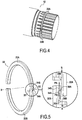
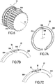
- the figures 4-5 and 6-7A respectively present a second and a third embodiment, fairly close to each other, of a connecting assembly.
- the second embodiment corresponds to the claimed invention, but not the third embodiment.
- the retaining means are formed by two hooks 34A and 34B, each being integrally formed. or in one piece in one end (first end) of one of the half-rings.
- the hooks 34A, 34B are made by making a notch 35A, 35B at the ends of the half-rings 22A, 22B.
- the notches 35A, 35B constitute hollows within the meaning of the present invention.
- Each of these hooks has the shape of a bent part (also denoted 34A, 34B), which extends from the first end of the half-ring in a direction perpendicular to the circumferential direction (according to the arrows X1, X2, on the Fig. 5 ).
- Each of these hooks or angled parts 34A, 34B comprises a retaining surface 36A, 36B whose outgoing perpendicular PA, PB is directed rearwardly with respect to the end direction (arrows A, B, Fig. 5 ) from the first end of the half-ring.
- This end direction is the circumferential direction at the first end of the considered half-ring, and more particularly in the outgoing direction with respect to this first end.
- the hooks 34A and 34B are shown engaged with each other.
- the surfaces 36A and 36B then face each other and their respective perpendicular directions are directed in the circumferential direction of the ring 22, parallel to the end directions A and B of the first ends of the rings, but in opposite directions.
- the main difference between the second and third embodiments lies in the orientation of the hooks 34A, 34B.
- the hooks 34A, 34B extend in the axial direction, that is to say the direction parallel to the X axis of the shaft (arrows X1, X2 parallel to the X axis, Fig. 5 ).
- the hooks 34A, 34B extend in a radial direction (radial direction R, Fig.7A ).
- the first ends of the half-rings are arranged such that to move these first ends from the mounted position to a position in which the first ends can move apart (in the circumferential direction), it is necessary to move the hook of one of the half-rings in the radial direction away from the shaft section 12.
- FIG. 6 A preferred embodiment of the method according to the invention is illustrated in particular by the figure 6 .
- the shaft section 12 is oriented horizontally.
- the half-rings 22A, 22B are then placed on either side of the shaft section, with their first ends arranged at the top, on the upper meridian of the shaft section.
- the weight of the half-rings keeps them in a stable position by preventing any radial centrifugal movement of their first ends which could allow them to disengage from one another.
- the second ends of the half rings i.e. the ends opposite to the first ends
- no retaining means is provided to prevent them from deviating from each other.
- the second ends are arranged identically to the first ends.
- the two half-rings 22A and 22B are identical. This embodiment assumes a certain flexibility of the half-rings in order to allow their installation.
- the half-rings are made of a very rigid material.
- FIGS. 7B and 7C show two arrangement possibilities of the retaining means according to the invention, when the half-rings are fairly rigid.
- the retaining means comprise a retaining part 32 rigidly fixed to the half-ring 22B.
- This retainer 32 is a small strip of elastic sheet metal.
- the first end 32B of this blade is fixed to the end of the half-ring 22B by welding.
- the second end is curved and has a bent portion 32A which extends in a re-entrant radial direction.
- the first end of the half-ring 22A for its part has a slot 33.
- the slot is arranged so that the bent part 32A of the retaining piece 32 can be inserted into the slot 33. In this position, the piece of retainer 32 prevents the first ends of the half-rings 22A and 22B from deviating from each other.
- Means to aid engagement such as a small chamfer in the direction of assembly can be provided.
- the blade length must be sufficient to allow bending with a force allowing the desired assembly, for example manually and without special tools.
- the elastic blade can for example be welded to the outside of the ring 22, in which case the diameter of the bore 24 of the host piece will be chosen to match the outside diameter of the ring at the location of the blades. .
- the bore 24 can retain the half-rings 22 at the location of the blades; or else, thinners can be provided on the half-rings 22a and 22B to accommodate the thickness of the blade, and the bore 24 of the receiving part can keep the half-rings in position over their entire periphery.
- the retaining means comprise two retaining pieces 32 rigidly fixed respectively to each of the half-rings 22A and 22B. These retainers are similar to the retainer 32 of the first variant. Each is also a small strip of elastic sheet metal. The free ends of these retainers each have a bent portion. These bent parts are curved: one radially outward (relative to the X axis) and the other radially inward.
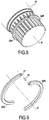
- the figures 8-9 and 10-11 respectively present a fourth and a fifth embodiment, fairly close to each other, of a connecting assembly.
- the fourth embodiment corresponds to the claimed invention, but not the fifth embodiment.
- the retaining means comprise a retaining part 40.
- This part 40 is distinct both from the shaft section and from the half-rings.
- it has the shape of a cylindrical pin 40, but other shapes are possible.
- the pin 40 constitutes a shearing member which enables the first ends of the half-rings to be joined to one another.
- the first ends of the half-rings 22A, 22B are arranged as follows.
- a flat surface is provided at the first end of each of these half-rings.
- the two flat surfaces thus arranged are arranged so as to be in contact with one another when the half-rings are in the mounted position, and so that in this position, their common perpendicular is perpendicular to the circumferential direction of the half rings.
- a bore 41 (constituting a hollow within the meaning of the invention) is drilled in each of these surfaces in the direction perpendicular to them. These bores are placed so as to be face to face in the mounted position of the half-rings and to allow the insertion of the pin 40.
- the pin 40 fixes the first ends of the two half-rings to one another and thus prevents them from deviating.
- the main difference between the fourth and fifth embodiments lies in the orientation of the pin 40 (and therefore the corresponding arrangement of the first ends of the half-rings):
- the pin In the fourth embodiment ( Fig. 8.9 ), the pin extends in a direction parallel to the X axis of the shaft ( Fig. 9 ); in the fifth embodiment ( Fig.10.11 ), it extends in the radial direction R.
- the second ends of the half-rings are free; conversely in the fifth embodiment, the second ends are arranged identically to the first ends, and the two half-rings 22A and 22B are identical.
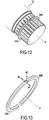
- the figures 12 and 13 illustrate a sixth embodiment.
- the retaining means also comprise a retaining part 40, separate from the shaft section and the half-rings, and having the shape of a cylindrical bar.
- planar surfaces are respectively provided at the first end of each of the half-rings 22A, 22B. They are arranged such that when the half-rings are in the mounted position, they are in contact with each other, and their common perpendicular is perpendicular to the circumferential direction at the first end of the half-rings.
- a semi-cylindrical groove (constituting a hollow within the meaning of the invention) is provided in each of these surfaces in the radial direction.
- the two grooves thus provided are placed so as to be face to face in the mounted position of the half-rings, and to be able to accommodate the bar 40.
- the half-rings are placed in the notches 26 of the grooves 20, between the axial stops 25.
- the axial stops 25 prevent an axial separation of the first ends of the half-rings in the axial direction (arrows X1 and X2, Fig.13 ). Therefore in this position of the ring, the two plane surfaces of the half-rings 22A, 22B remain in contact with each other.
- the bar 40 therefore remains in contact both with the groove formed in the half-ring 22A, and with the groove formed in the half-ring 22B. It thus prevents the first ends of the half-rings from moving away from one another in the circumferential direction.
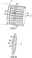
- the figures 14-16 and 17-18 respectively present a seventh and an eighth embodiment, fairly close to each other, of a connecting assembly according to the invention.
- the retaining means comprise two hooks 34A and 34B, each having an elbow portion (also 34A, 34B) integrated into the first end of each of the half-rings and extending in a direction perpendicular to the direction. circumferential.
- this direction is the radial direction (R), while in the eighth embodiment, this direction is the axial direction (X) of the shaft section.
- the first ends of the half-rings are prevented from moving away from each other by a retaining piece, namely in this case, the shaft section 12 itself.
- the shaft section has a radial hole 42 ( Fig.14.15 ), designed to receive the hooks 34A, 34B.
- the radial hole 42 is preferably placed substantially towards the top of the wheel spindle 12 when mounting the cylinder block on the spindle 12.
- the force of gravity is therefore exerted along the arrow G.
- the half-rings 22A and 22B shown on the figure 16 are placed on the wheel spindle 12 such that the hooks 24A and 34B engage in the hole 42 located at the top of the spindle 12.
- this assembly does not require any jamming of the parts, and therefore allows very easy manual or robotic positioning.
- the hooks 34A, 34B are formed in the axial direction and engaged between two ribs 20B, 20A of the splines 20 of the shaft section 12.
- the side walls of the ribs 20B, 20A constitute locking surfaces which prevent the first ends of the half rings to move away from each other.
- the first end of a first of the half-rings comprises a cylindrical rod 44 which extends in the circumferential direction in the extension of the body of the half-ring; the first end of the second half-ring conversely comprises a cylindrical bore 46 which extends, also in the circumferential direction, inside the body of the half-ring.
- the rod 44 has an outside diameter very slightly greater, or even equal (or even slightly less), to the inside diameter of the bore 46. Also, when the rod 44 is engaged in the bore 46, a certain friction occurs. between the rod 44 and the bore 46.
- the retaining means generally have to fulfill their function (prevent the first ends of the two half-rings from moving away from each other) only when the half-rings are assembled, and until they are capped or covered (at least in part) by the reception room.
- they may be formed from a rigid material (as for example in the first embodiment, Fig. 2 ), they can also be made at least partially of flexible material, and thus shaped only just before assembly. This may for example be the case with hooks 34A, 34B of the seventh and eighth embodiment, which can be made of a material which can be deformed by hand.
- the holding in position of the half-rings by the retaining means is carried out provisionally during the first step a) of the assembly.
- the retaining action provided by the retaining means may be relatively weak, that is to say just sufficient to prevent the rings from falling under the effect of their own weight.
- the holding in the final position of the half rings allowing them to perform their function of axially holding the host piece on the machine or the vehicle, is secured by the external axial covering of the half-rings by the reception piece.
- the half-rings cannot escape.
- the retaining means can therefore be considered as first retaining means, used initially on a temporary basis to allow the two half-rings to be maintained in the desired mounting position. ; and the connecting assembly is completed by second retaining means which are produced by the axial covering of the half rings by the receiving part in order to hold the half rings radially against the shaft section.
- connection assembly according to the invention is particularly advantageous for fitting the rockets with the wheels of machines, vehicles or trailers which use hydraulic motors. It is particularly advantageous for equipping the wheel spindles of these vehicles with hydraulic assistance motors, more particularly in the particular case of multilobe cam motors, with rotating cam connected to a hub and with a fixed cylinder block carried by the spindle. wheel.
- the linkage assembly facilitates the maintenance of hydraulic motors carried by wheel knuckles in a horizontal position, by allowing rapid assembly or disassembly of the stop ring. It advantageously applies to machines and vehicles equipped with temporary traction assistance with disengageable or declutchable cam motors by retraction of the pistons or by disengaging the cylinder block from the shaft. It advantageously applies to the steering wheel spindles of such machines or vehicles.
- this connecting assembly is advantageously applied to the mounting of hydraulic motors on the axles of machines or semi-finished vehicles in a horizontal position.
Landscapes
- Engineering & Computer Science (AREA)
- General Engineering & Computer Science (AREA)
- Mechanical Engineering (AREA)
- Snaps, Bayonet Connections, Set Pins, And Snap Rings (AREA)
- Clamps And Clips (AREA)
Claims (15)
- Verbindungsanordnung, umfassend ein Aufnahmestück (14), einen Sperrring (22) und einen Wellenabschnitt (12) mit einer Vielzahl von axialen Anschlägen (25), die dafür geeignet sind, um eine axiale Verschiebung des Rings zu verhindern, wenn dieser um den genannten Abschnitt angeordnet ist,
wobei das Aufnahmestück (14) eine Bohrung (16) aufweist, um den Wellenabschnitt aufzunehmen,
wobei der Ring im Wesentlichen aus zwei Halbringen (22A, 22B) besteht, die in Bezug aufeinander verschiebbar sind, wobei jeder Halbring ein erstes Ende und ein zweites Ende aufweist,
wobei die Anordnung Haltemittel (34A, 34B) aufweist, die dafür geeignet sind, wenn der Ring in eine Position platziert wird, in der er um den genannten Abschnitt montiert ist und axial von den axialen Anschlägen (25) gehalten ist, zu verhindern, dass sich das erste Ende eines ersten der genannten Halbringe und das erste Ende des zweiten der genannten Halbringe voneinander in einer Umfangsrichtung beabstanden,
wobei der Ring in der montierten Position eine relative Verschiebung in einer axialen Richtung (X) des Wellenabschnitts (12) in Bezug auf das Aufnahmestück (14) verhindert,
wobei die Verbindungsanordnung derart eingerichtet ist, dass in der montierten Position der Ring (22) zwischen dem Wellenabschnitt (12) und dem Aufnahmestück (14) angeordnet ist und radial gegen den Wellenabschnitt (12) durch das Aufnahmestück (14) gehalten wird,
wobei die Verbindungsanordnung dadurch gekennzeichnet ist, dass die Haltemittel eingerichtet sind, um die ersten Enden der Halbringe zu halten, während die zweiten Enden frei sind. - Verbindungsanordnung nach Anspruch 1, wobei das Aufnahmestück ein Zylinderblock (14) eines Hydraulikmotors ist, insbesondere eines Hydraulikmotors mit radialen Kolben.
- Verbindungsanordnung nach Anspruch 1 oder 2, wobei der Wellenabschnitt (12) ein Wellenabschnitt eines Motorabgangs und/oder eines Achsschenkels ist.
- Verbindungsanordnung nach einem der Ansprüche 1 bis 3, wobei die ersten Enden einen gebogenen Abschnitt (34A, 34B) umfassen, der sich in einer radialen Richtung (R) erstreckt.
- Verbindungsanordnung nach einem der Ansprüche 1 bis 3, wobei die ersten Enden einen gebogenen Abschnitt (34A, 34B) umfassen, der sich in einer Richtung parallel zu einer Achse (X) der Welle erstreckt.
- Verbindungsanordnung nach einem der Ansprüche 1 bis 5, wobei die Haltemittel ein Haltestück (32) umfassen, das starr an einem der Halbringe (22A, 22B) befestigt ist.
- Verbindungsanordnung nach einem der Ansprüche 1 bis 5, wobei die Haltemittel einerseits aus einem integralen Teil eines der genannten ersten Halbringe und andererseits aus einem integralen Teil des anderen der genannten Halbringe bestehen.
- Verbindungsanordnung nach einem der Ansprüche 1 bis 7, wobei die Haltemittel derart eingerichtet sind, dass jede relative Verschiebung der genannten ersten Enden aus der montierten Position in eine Position, in der die Beabstandung der genannten ersten Enden in der Umfangsrichtung möglich ist, eine radiale Verschiebung mindestens eines der ersten Enden umfasst.
- Verbindungsanordnung nach einem der Ansprüche 1 bis 8, wobei das erste Ende jedes der Halbringe eine Haltefläche (36A, 36B) umfasst, deren austretende Senkrechte nach hinten in Bezug auf die Richtung (A, B) des ersten Endes des Halbrings gerichtet ist, wobei die Halteflächen der beiden Halbringe eingerichtet sind, um in eine Eingriffsposition miteinander versetzt werden zu können, in der sie direkt miteinander in Eingriff stehen, um zu verhindern, dass sich die genannten ersten Enden voneinander in einer Umfangsrichtung beabstanden, oder auch um sie in einer konstanten Distanz voneinander zu halten, wenn sich der Ring in der montierten Position befindet.
- Verbindungsanordnung nach einem der Ansprüche 1 bis 9, wobei mindestens einer der Halbringe einen Hohlraum (35A, 35B; 41; 42) in einer Richtung im Wesentlichen rechtwinklig zur Umfangsrichtung umfasst,
wobei die Haltemittel mindestens einen Vorsprung umfassen, der dafür geeignet ist, um in den genannten Hohlraum platziert zu werden, und
der Vorsprung mit dem anderen Halbring hinsichtlich der Verschiebungen in der Umfangsrichtung fest verbunden ist. - Verbindungsanordnung nach einem der Ansprüche 1 bis 10, wobei die Haltemittel ein Haltestück (40, 12) umfassen, das in Bezug auf die Halbringe verschiebbar ist, und wobei das Haltestück dafür geeignet ist, um derart in Kontakt mit den Halteflächen gebracht zu werden, dass eine Kraft übertragen wird, die zwischen ihnen ausgeübt wird, und um folglich die Beabstandung der genannten ersten Enden in Bezug aufeinander zu verhindern.
- Verbindungsanordnung nach Anspruch 11, wobei das Haltestück der Wellenabschnitt (12) ist.
- Verfahren zum Montieren einer Verbindungsanordnung gemäß einem der Ansprüche 1 bis 12, umfassend die folgenden Schritte:a) die beiden Halbringe werden auf den Wellenabschnitt platziert, indem die Haltemittel derart verwendet werden, dass sich das erste Ende eines ersten der genannten Halbringe und das erste Ende des zweiten der genannten Halteringe nicht in Umfangsrichtung voneinander beabstanden können, wobei die zweiten Enden der genannten Halbringe frei bleiben,b) das Aufnahmestück (14) wird auf dem Wellenabschnitt derart in Eingriff gebracht, dass der Wellenabschnitt in der Bohrung (16) des Aufnahmestücks angeordnet wird, wobei der Ring (22) zwischen dem Wellenabschnitt (12) und dem Aufnahmestück (14) angeordnet wird, und dass das Aufnahmestück den Ring (22) radial gegen den Wellenabschnitt hält.
- Montageverfahren nach Anspruch 13, wobei der Wellenabschnitt während der Schritte a) bis c) horizontal angeordnet wird.
- Montageverfahren nach Anspruch 13 oder 14, wobei in Schritt a) die ersten Enden der Halbringe am oberen Meridian des Wellenabschnitts angeordnet sind.
Applications Claiming Priority (2)
| Application Number | Priority Date | Filing Date | Title |
|---|---|---|---|
| FR1360609A FR3012543B1 (fr) | 2013-10-30 | 2013-10-30 | Ensemble de liaison par anneau d'arret pour troncon d'arbre |
| PCT/FR2014/052763 WO2015063423A1 (fr) | 2013-10-30 | 2014-10-30 | Ensemble de liaison par anneau d'arrêt pour tronçon d'arbre. procédé de montage d'un tel ensemble de liaison |
Publications (2)
| Publication Number | Publication Date |
|---|---|
| EP3063418A1 EP3063418A1 (de) | 2016-09-07 |
| EP3063418B1 true EP3063418B1 (de) | 2020-10-07 |
Family
ID=49759401
Family Applications (1)
| Application Number | Title | Priority Date | Filing Date |
|---|---|---|---|
| EP14805993.4A Active EP3063418B1 (de) | 2013-10-30 | 2014-10-30 | Verbindungsanordnung mit einem haltering für eine welle verfahren zur montage solch einer verbindungsanordnung |
Country Status (4)
| Country | Link |
|---|---|
| EP (1) | EP3063418B1 (de) |
| FR (1) | FR3012543B1 (de) |
| RU (1) | RU2692462C2 (de) |
| WO (1) | WO2015063423A1 (de) |
Families Citing this family (6)
| Publication number | Priority date | Publication date | Assignee | Title |
|---|---|---|---|---|
| US9714681B2 (en) * | 2015-09-28 | 2017-07-25 | Deer & Company | High-speed snap ring and snap ring retention method |
| US10954984B2 (en) * | 2016-11-30 | 2021-03-23 | Standard Lifters, Inc. | Collar and shaft assembly |
| FR3071391B1 (fr) | 2017-09-22 | 2020-01-03 | Poclain Hydraulics Industrie | Bloc d'alimentation pour au moins une machine hydraulique |
| US11293479B2 (en) | 2019-05-21 | 2022-04-05 | Bowerbags Llc | Modular clipping system |
| EP3913250B1 (de) * | 2020-05-21 | 2023-06-28 | Hamilton Sundstrand Corporation | Generatorwellenanordnung |
| FR3171262A3 (fr) | 2025-01-14 | 2026-07-17 | Poclain Hydraulics Industrie | Nouveau dispositif d’assistance |
Family Cites Families (14)
| Publication number | Priority date | Publication date | Assignee | Title |
|---|---|---|---|---|
| US1638209A (en) * | 1925-10-01 | 1927-08-09 | Niebuhr William Charles | Separable ring |
| US2036152A (en) * | 1935-10-11 | 1936-03-31 | Langman Ransom | Easily removable washer |
| AT236709B (de) * | 1945-06-27 | 1964-11-10 | Waldes Kohinoor Inc | Einrichtung zum Sichern eines Maschinenteiles auf einer Welle gegen axiale Verschiebung |
| US2713806A (en) * | 1952-03-20 | 1955-07-26 | Ruez M Dodge | End play take up washer |
| US3179450A (en) * | 1961-08-24 | 1965-04-20 | Florian B Recker | Coupling |
| DE2236179C2 (de) * | 1972-07-24 | 1974-07-25 | Kufsteiner Armaturen- Und Metallwarenfabrik Gmbh, Kufstein (Oesterreich) | Vorrichtung zur axialen Verbindung einer Hülse an einem darin anzuordnenden Körper, insbesondere eines Ventilgriffs an einer Ventilspindel |
| JPS587139Y2 (ja) * | 1975-07-29 | 1983-02-08 | 三菱自動車工業株式会社 | ヘンソクキベアリングヌケドメソウチ |
| JPS6266011U (de) * | 1985-10-16 | 1987-04-24 | ||
| EP0239556B1 (de) * | 1986-03-25 | 1990-10-31 | AB Sandvik Coromant | Kuppeleinrichtung für zwei Teile |
| RU1724U1 (ru) * | 1992-03-26 | 1996-02-16 | Спирин Геннадий Александрович | Соединение осей |
| DE10244029B4 (de) * | 2002-09-21 | 2004-08-05 | Kuka Roboter Gmbh | Ringteil aus mindestens zwei Teilringen und Verfahren zur Verbindung der Teilringe zum geschlossenen Ringteil |
| US20060182518A1 (en) * | 2003-04-21 | 2006-08-17 | Underwood J L | Molded washer assembly |
| US7011482B2 (en) * | 2003-04-21 | 2006-03-14 | L.L. Culmat, L.P. | Molded washer |
| DE102012024425A1 (de) * | 2012-12-14 | 2014-06-18 | Getrag Getriebe- Und Zahnradfabrik Hermann Hagenmeyer Gmbh & Cie Kg | Scheibenanordnung für eine Axiallageranordnung |
-
2013
- 2013-10-30 FR FR1360609A patent/FR3012543B1/fr not_active Expired - Fee Related
-
2014
- 2014-10-30 EP EP14805993.4A patent/EP3063418B1/de active Active
- 2014-10-30 WO PCT/FR2014/052763 patent/WO2015063423A1/fr not_active Ceased
- 2014-10-30 RU RU2016121034A patent/RU2692462C2/ru active
Non-Patent Citations (1)
| Title |
|---|
| None * |
Also Published As
| Publication number | Publication date |
|---|---|
| RU2016121034A3 (de) | 2018-03-28 |
| RU2016121034A (ru) | 2017-12-05 |
| FR3012543A1 (fr) | 2015-05-01 |
| FR3012543B1 (fr) | 2016-04-15 |
| RU2692462C2 (ru) | 2019-06-24 |
| EP3063418A1 (de) | 2016-09-07 |
| WO2015063423A1 (fr) | 2015-05-07 |
Similar Documents
| Publication | Publication Date | Title |
|---|---|---|
| EP0300890B1 (de) | Schnellkupplung zwischen zwei Wellen oder dergleichen | |
| WO2015063423A1 (fr) | Ensemble de liaison par anneau d'arrêt pour tronçon d'arbre. procédé de montage d'un tel ensemble de liaison | |
| FR2972963A1 (fr) | Element de suspension pour machine automotrice | |
| EP0057348B1 (de) | Schrägwälzlager mit zwei Reihen Wälzkörper und Verfahren zum Zusammenbau | |
| FR3037115A1 (fr) | Dispositif de poulie pour galet tendeur ou enrouleur | |
| EP2389264B1 (de) | Werkzeugspannfutter zum vorsehen an einer rotierenden maschine | |
| WO2019057880A1 (fr) | Douille de fixation pour l'assemblage de structures et fixation associée | |
| FR2775741A1 (fr) | Organe de transmission mecanique et son application a un joint mecanique homocinetique | |
| FR2691768A1 (fr) | Joint à tripode. | |
| EP2712745B1 (de) | Lenkstange mit Verstärkungsbuchse | |
| EP2480379B1 (de) | Greifwerkzeug | |
| EP0913595B1 (de) | Herstellungsverfahren eines Innenringes von einem metallischen Kugelgelenk und so erhaltenes Kugelgelenk | |
| EP1500460A1 (de) | Verfahren zur Herstellung eines Befestigungskragens mit einem allmählichen Übergang | |
| EP1431597B1 (de) | Herstellungsverfahren eines metallischen Kugelgelenks | |
| EP1626891A1 (de) | Verfahren zur befestigung eines fahrradrades an einem rahmen | |
| FR3115849A1 (fr) | Differentiel de boîte de vitesse a joncs d’arret d’axe porte-satellite | |
| FR3064326A1 (fr) | Element d'engrenage a rouleaux | |
| EP0300883A1 (de) | Schnellkupplung zwischen zwei ein Drehmoment übertragenden Elementen | |
| EP0333539B1 (de) | Lösbarer Linearschrittmotor mit einem rückzentrierten Läufer | |
| FR2999969A1 (fr) | Procede d’assemblage d’une bague de roulement sur une portee cylindrique et accessoire d’assemblage | |
| EP3250842B1 (de) | Torsionsdämpfer mit gerade schraubenfeder | |
| EP3329138B1 (de) | Faltenbalg für antriebsgelenk und zugehörige getriebeanordnung | |
| EP3163105A1 (de) | Montagering und führungslager mit zwei innenringen, das mit einem solchen montagering ausgestattet ist | |
| FR2732735A1 (fr) | Joint de transmission homocinetique | |
| EP0940529A1 (de) | Doppelsicherheitszylinder |
Legal Events
| Date | Code | Title | Description |
|---|---|---|---|
| PUAI | Public reference made under article 153(3) epc to a published international application that has entered the european phase |
Free format text: ORIGINAL CODE: 0009012 |
|
| 17P | Request for examination filed |
Effective date: 20160527 |
|
| AK | Designated contracting states |
Kind code of ref document: A1 Designated state(s): AL AT BE BG CH CY CZ DE DK EE ES FI FR GB GR HR HU IE IS IT LI LT LU LV MC MK MT NL NO PL PT RO RS SE SI SK SM TR |
|
| AX | Request for extension of the european patent |
Extension state: BA ME |
|
| DAX | Request for extension of the european patent (deleted) | ||
| STAA | Information on the status of an ep patent application or granted ep patent |
Free format text: STATUS: EXAMINATION IS IN PROGRESS |
|
| 17Q | First examination report despatched |
Effective date: 20180921 |
|
| GRAP | Despatch of communication of intention to grant a patent |
Free format text: ORIGINAL CODE: EPIDOSNIGR1 |
|
| STAA | Information on the status of an ep patent application or granted ep patent |
Free format text: STATUS: GRANT OF PATENT IS INTENDED |
|
| INTG | Intention to grant announced |
Effective date: 20191015 |
|
| GRAJ | Information related to disapproval of communication of intention to grant by the applicant or resumption of examination proceedings by the epo deleted |
Free format text: ORIGINAL CODE: EPIDOSDIGR1 |
|
| STAA | Information on the status of an ep patent application or granted ep patent |
Free format text: STATUS: EXAMINATION IS IN PROGRESS |
|
| INTC | Intention to grant announced (deleted) | ||
| GRAP | Despatch of communication of intention to grant a patent |
Free format text: ORIGINAL CODE: EPIDOSNIGR1 |
|
| STAA | Information on the status of an ep patent application or granted ep patent |
Free format text: STATUS: GRANT OF PATENT IS INTENDED |
|
| INTG | Intention to grant announced |
Effective date: 20200421 |
|
| GRAS | Grant fee paid |
Free format text: ORIGINAL CODE: EPIDOSNIGR3 |
|
| GRAA | (expected) grant |
Free format text: ORIGINAL CODE: 0009210 |
|
| STAA | Information on the status of an ep patent application or granted ep patent |
Free format text: STATUS: THE PATENT HAS BEEN GRANTED |
|
| AK | Designated contracting states |
Kind code of ref document: B1 Designated state(s): AL AT BE BG CH CY CZ DE DK EE ES FI FR GB GR HR HU IE IS IT LI LT LU LV MC MK MT NL NO PL PT RO RS SE SI SK SM TR |
|
| REG | Reference to a national code |
Ref country code: GB Ref legal event code: FG4D Free format text: NOT ENGLISH |
|
| REG | Reference to a national code |
Ref country code: AT Ref legal event code: REF Ref document number: 1321450 Country of ref document: AT Kind code of ref document: T Effective date: 20201015 Ref country code: CH Ref legal event code: EP |
|
| REG | Reference to a national code |
Ref country code: DE Ref legal event code: R096 Ref document number: 602014071043 Country of ref document: DE |
|
| REG | Reference to a national code |
Ref country code: IE Ref legal event code: FG4D Free format text: LANGUAGE OF EP DOCUMENT: FRENCH |
|
| REG | Reference to a national code |
Ref country code: NL Ref legal event code: MP Effective date: 20201007 |
|
| REG | Reference to a national code |
Ref country code: AT Ref legal event code: MK05 Ref document number: 1321450 Country of ref document: AT Kind code of ref document: T Effective date: 20201007 |
|
| PG25 | Lapsed in a contracting state [announced via postgrant information from national office to epo] |
Ref country code: GR Free format text: LAPSE BECAUSE OF FAILURE TO SUBMIT A TRANSLATION OF THE DESCRIPTION OR TO PAY THE FEE WITHIN THE PRESCRIBED TIME-LIMIT Effective date: 20210108 Ref country code: PT Free format text: LAPSE BECAUSE OF FAILURE TO SUBMIT A TRANSLATION OF THE DESCRIPTION OR TO PAY THE FEE WITHIN THE PRESCRIBED TIME-LIMIT Effective date: 20210208 Ref country code: NO Free format text: LAPSE BECAUSE OF FAILURE TO SUBMIT A TRANSLATION OF THE DESCRIPTION OR TO PAY THE FEE WITHIN THE PRESCRIBED TIME-LIMIT Effective date: 20210107 Ref country code: NL Free format text: LAPSE BECAUSE OF FAILURE TO SUBMIT A TRANSLATION OF THE DESCRIPTION OR TO PAY THE FEE WITHIN THE PRESCRIBED TIME-LIMIT Effective date: 20201007 Ref country code: RS Free format text: LAPSE BECAUSE OF FAILURE TO SUBMIT A TRANSLATION OF THE DESCRIPTION OR TO PAY THE FEE WITHIN THE PRESCRIBED TIME-LIMIT Effective date: 20201007 Ref country code: FI Free format text: LAPSE BECAUSE OF FAILURE TO SUBMIT A TRANSLATION OF THE DESCRIPTION OR TO PAY THE FEE WITHIN THE PRESCRIBED TIME-LIMIT Effective date: 20201007 |
|
| REG | Reference to a national code |
Ref country code: LT Ref legal event code: MG4D |
|
| PG25 | Lapsed in a contracting state [announced via postgrant information from national office to epo] |
Ref country code: SE Free format text: LAPSE BECAUSE OF FAILURE TO SUBMIT A TRANSLATION OF THE DESCRIPTION OR TO PAY THE FEE WITHIN THE PRESCRIBED TIME-LIMIT Effective date: 20201007 Ref country code: IS Free format text: LAPSE BECAUSE OF FAILURE TO SUBMIT A TRANSLATION OF THE DESCRIPTION OR TO PAY THE FEE WITHIN THE PRESCRIBED TIME-LIMIT Effective date: 20210207 Ref country code: LV Free format text: LAPSE BECAUSE OF FAILURE TO SUBMIT A TRANSLATION OF THE DESCRIPTION OR TO PAY THE FEE WITHIN THE PRESCRIBED TIME-LIMIT Effective date: 20201007 Ref country code: PL Free format text: LAPSE BECAUSE OF FAILURE TO SUBMIT A TRANSLATION OF THE DESCRIPTION OR TO PAY THE FEE WITHIN THE PRESCRIBED TIME-LIMIT Effective date: 20201007 Ref country code: BG Free format text: LAPSE BECAUSE OF FAILURE TO SUBMIT A TRANSLATION OF THE DESCRIPTION OR TO PAY THE FEE WITHIN THE PRESCRIBED TIME-LIMIT Effective date: 20210107 Ref country code: AT Free format text: LAPSE BECAUSE OF FAILURE TO SUBMIT A TRANSLATION OF THE DESCRIPTION OR TO PAY THE FEE WITHIN THE PRESCRIBED TIME-LIMIT Effective date: 20201007 Ref country code: ES Free format text: LAPSE BECAUSE OF FAILURE TO SUBMIT A TRANSLATION OF THE DESCRIPTION OR TO PAY THE FEE WITHIN THE PRESCRIBED TIME-LIMIT Effective date: 20201007 |
|
| REG | Reference to a national code |
Ref country code: CH Ref legal event code: PL |
|
| PG25 | Lapsed in a contracting state [announced via postgrant information from national office to epo] |
Ref country code: HR Free format text: LAPSE BECAUSE OF FAILURE TO SUBMIT A TRANSLATION OF THE DESCRIPTION OR TO PAY THE FEE WITHIN THE PRESCRIBED TIME-LIMIT Effective date: 20201007 Ref country code: LU Free format text: LAPSE BECAUSE OF NON-PAYMENT OF DUE FEES Effective date: 20201030 |
|
| REG | Reference to a national code |
Ref country code: DE Ref legal event code: R097 Ref document number: 602014071043 Country of ref document: DE |
|
| REG | Reference to a national code |
Ref country code: BE Ref legal event code: MM Effective date: 20201031 |
|
| PG25 | Lapsed in a contracting state [announced via postgrant information from national office to epo] |
Ref country code: MC Free format text: LAPSE BECAUSE OF FAILURE TO SUBMIT A TRANSLATION OF THE DESCRIPTION OR TO PAY THE FEE WITHIN THE PRESCRIBED TIME-LIMIT Effective date: 20201007 Ref country code: LT Free format text: LAPSE BECAUSE OF FAILURE TO SUBMIT A TRANSLATION OF THE DESCRIPTION OR TO PAY THE FEE WITHIN THE PRESCRIBED TIME-LIMIT Effective date: 20201007 Ref country code: SK Free format text: LAPSE BECAUSE OF FAILURE TO SUBMIT A TRANSLATION OF THE DESCRIPTION OR TO PAY THE FEE WITHIN THE PRESCRIBED TIME-LIMIT Effective date: 20201007 Ref country code: RO Free format text: LAPSE BECAUSE OF FAILURE TO SUBMIT A TRANSLATION OF THE DESCRIPTION OR TO PAY THE FEE WITHIN THE PRESCRIBED TIME-LIMIT Effective date: 20201007 Ref country code: SM Free format text: LAPSE BECAUSE OF FAILURE TO SUBMIT A TRANSLATION OF THE DESCRIPTION OR TO PAY THE FEE WITHIN THE PRESCRIBED TIME-LIMIT Effective date: 20201007 Ref country code: EE Free format text: LAPSE BECAUSE OF FAILURE TO SUBMIT A TRANSLATION OF THE DESCRIPTION OR TO PAY THE FEE WITHIN THE PRESCRIBED TIME-LIMIT Effective date: 20201007 Ref country code: CZ Free format text: LAPSE BECAUSE OF FAILURE TO SUBMIT A TRANSLATION OF THE DESCRIPTION OR TO PAY THE FEE WITHIN THE PRESCRIBED TIME-LIMIT Effective date: 20201007 |
|
| PLBE | No opposition filed within time limit |
Free format text: ORIGINAL CODE: 0009261 |
|
| STAA | Information on the status of an ep patent application or granted ep patent |
Free format text: STATUS: NO OPPOSITION FILED WITHIN TIME LIMIT |
|
| PG25 | Lapsed in a contracting state [announced via postgrant information from national office to epo] |
Ref country code: DK Free format text: LAPSE BECAUSE OF FAILURE TO SUBMIT A TRANSLATION OF THE DESCRIPTION OR TO PAY THE FEE WITHIN THE PRESCRIBED TIME-LIMIT Effective date: 20201007 Ref country code: CH Free format text: LAPSE BECAUSE OF NON-PAYMENT OF DUE FEES Effective date: 20201031 Ref country code: BE Free format text: LAPSE BECAUSE OF NON-PAYMENT OF DUE FEES Effective date: 20201031 Ref country code: LI Free format text: LAPSE BECAUSE OF NON-PAYMENT OF DUE FEES Effective date: 20201031 |
|
| 26N | No opposition filed |
Effective date: 20210708 |
|
| GBPC | Gb: european patent ceased through non-payment of renewal fee |
Effective date: 20210107 |
|
| PG25 | Lapsed in a contracting state [announced via postgrant information from national office to epo] |
Ref country code: IT Free format text: LAPSE BECAUSE OF FAILURE TO SUBMIT A TRANSLATION OF THE DESCRIPTION OR TO PAY THE FEE WITHIN THE PRESCRIBED TIME-LIMIT Effective date: 20201007 Ref country code: IE Free format text: LAPSE BECAUSE OF NON-PAYMENT OF DUE FEES Effective date: 20201030 Ref country code: AL Free format text: LAPSE BECAUSE OF FAILURE TO SUBMIT A TRANSLATION OF THE DESCRIPTION OR TO PAY THE FEE WITHIN THE PRESCRIBED TIME-LIMIT Effective date: 20201007 |
|
| PG25 | Lapsed in a contracting state [announced via postgrant information from national office to epo] |
Ref country code: GB Free format text: LAPSE BECAUSE OF NON-PAYMENT OF DUE FEES Effective date: 20210107 Ref country code: SI Free format text: LAPSE BECAUSE OF FAILURE TO SUBMIT A TRANSLATION OF THE DESCRIPTION OR TO PAY THE FEE WITHIN THE PRESCRIBED TIME-LIMIT Effective date: 20201007 |
|
| PG25 | Lapsed in a contracting state [announced via postgrant information from national office to epo] |
Ref country code: IS Free format text: LAPSE BECAUSE OF FAILURE TO SUBMIT A TRANSLATION OF THE DESCRIPTION OR TO PAY THE FEE WITHIN THE PRESCRIBED TIME-LIMIT Effective date: 20210207 Ref country code: TR Free format text: LAPSE BECAUSE OF FAILURE TO SUBMIT A TRANSLATION OF THE DESCRIPTION OR TO PAY THE FEE WITHIN THE PRESCRIBED TIME-LIMIT Effective date: 20201007 Ref country code: MT Free format text: LAPSE BECAUSE OF FAILURE TO SUBMIT A TRANSLATION OF THE DESCRIPTION OR TO PAY THE FEE WITHIN THE PRESCRIBED TIME-LIMIT Effective date: 20201007 Ref country code: CY Free format text: LAPSE BECAUSE OF FAILURE TO SUBMIT A TRANSLATION OF THE DESCRIPTION OR TO PAY THE FEE WITHIN THE PRESCRIBED TIME-LIMIT Effective date: 20201007 |
|
| PG25 | Lapsed in a contracting state [announced via postgrant information from national office to epo] |
Ref country code: MK Free format text: LAPSE BECAUSE OF FAILURE TO SUBMIT A TRANSLATION OF THE DESCRIPTION OR TO PAY THE FEE WITHIN THE PRESCRIBED TIME-LIMIT Effective date: 20201007 |
|
| P01 | Opt-out of the competence of the unified patent court (upc) registered |
Effective date: 20230513 |
|
| PGFP | Annual fee paid to national office [announced via postgrant information from national office to epo] |
Ref country code: DE Payment date: 20251015 Year of fee payment: 12 |
|
| PGFP | Annual fee paid to national office [announced via postgrant information from national office to epo] |
Ref country code: FR Payment date: 20251021 Year of fee payment: 12 |