EP3062091B1 - Procédé de suivi de la déformation d'un matériau élastique et dispositif d'imagerie pour image de projection de matériau élastique - Google Patents
Procédé de suivi de la déformation d'un matériau élastique et dispositif d'imagerie pour image de projection de matériau élastique Download PDFInfo
- Publication number
- EP3062091B1 EP3062091B1 EP14862786.2A EP14862786A EP3062091B1 EP 3062091 B1 EP3062091 B1 EP 3062091B1 EP 14862786 A EP14862786 A EP 14862786A EP 3062091 B1 EP3062091 B1 EP 3062091B1
- Authority
- EP
- European Patent Office
- Prior art keywords
- elastic material
- capture
- capturing
- contacted surface
- projection image
- Prior art date
- Legal status (The legal status is an assumption and is not a legal conclusion. Google has not performed a legal analysis and makes no representation as to the accuracy of the status listed.)
- Active
Links
- 239000013013 elastic material Substances 0.000 title claims description 324
- 238000000034 method Methods 0.000 title claims description 81
- 238000003384 imaging method Methods 0.000 title 1
- 238000012544 monitoring process Methods 0.000 title 1
- 230000002093 peripheral effect Effects 0.000 claims description 49
- 238000001514 detection method Methods 0.000 claims description 36
- 230000033001 locomotion Effects 0.000 claims description 31
- 239000012530 fluid Substances 0.000 claims description 24
- 239000002245 particle Substances 0.000 claims description 24
- 239000003550 marker Substances 0.000 claims description 19
- 229920001971 elastomer Polymers 0.000 claims description 18
- 238000003825 pressing Methods 0.000 claims description 17
- 239000005060 rubber Substances 0.000 claims description 13
- 239000000806 elastomer Substances 0.000 claims description 5
- 238000006243 chemical reaction Methods 0.000 description 11
- OAICVXFJPJFONN-UHFFFAOYSA-N Phosphorus Chemical compound [P] OAICVXFJPJFONN-UHFFFAOYSA-N 0.000 description 6
- 238000005096 rolling process Methods 0.000 description 5
- NINIDFKCEFEMDL-UHFFFAOYSA-N Sulfur Chemical compound [S] NINIDFKCEFEMDL-UHFFFAOYSA-N 0.000 description 4
- PNEYBMLMFCGWSK-UHFFFAOYSA-N aluminium oxide Inorganic materials [O-2].[O-2].[O-2].[Al+3].[Al+3] PNEYBMLMFCGWSK-UHFFFAOYSA-N 0.000 description 4
- 239000000463 material Substances 0.000 description 4
- 239000000126 substance Substances 0.000 description 4
- 229910052717 sulfur Inorganic materials 0.000 description 4
- 239000011593 sulfur Substances 0.000 description 4
- XLYOFNOQVPJJNP-UHFFFAOYSA-N water Substances O XLYOFNOQVPJJNP-UHFFFAOYSA-N 0.000 description 4
- 239000006229 carbon black Substances 0.000 description 3
- 230000006835 compression Effects 0.000 description 3
- 238000007906 compression Methods 0.000 description 3
- 239000002783 friction material Substances 0.000 description 3
- 238000004073 vulcanization Methods 0.000 description 3
- 239000010426 asphalt Substances 0.000 description 2
- TZCXTZWJZNENPQ-UHFFFAOYSA-L barium sulfate Chemical compound [Ba+2].[O-]S([O-])(=O)=O TZCXTZWJZNENPQ-UHFFFAOYSA-L 0.000 description 2
- 238000002591 computed tomography Methods 0.000 description 2
- 230000001678 irradiating effect Effects 0.000 description 2
- 238000004088 simulation Methods 0.000 description 2
- 229920003048 styrene butadiene rubber Polymers 0.000 description 2
- ZCYVEMRRCGMTRW-UHFFFAOYSA-N 7553-56-2 Chemical compound [I] ZCYVEMRRCGMTRW-UHFFFAOYSA-N 0.000 description 1
- 239000006237 Intermediate SAF Substances 0.000 description 1
- 230000001133 acceleration Effects 0.000 description 1
- 229910052788 barium Inorganic materials 0.000 description 1
- DSAJWYNOEDNPEQ-UHFFFAOYSA-N barium atom Chemical compound [Ba] DSAJWYNOEDNPEQ-UHFFFAOYSA-N 0.000 description 1
- 230000005540 biological transmission Effects 0.000 description 1
- 239000002872 contrast media Substances 0.000 description 1
- 125000004122 cyclic group Chemical group 0.000 description 1
- 230000000694 effects Effects 0.000 description 1
- 239000013536 elastomeric material Substances 0.000 description 1
- 238000005516 engineering process Methods 0.000 description 1
- 230000005484 gravity Effects 0.000 description 1
- 229910052740 iodine Inorganic materials 0.000 description 1
- 239000011630 iodine Substances 0.000 description 1
- IUJLOAKJZQBENM-UHFFFAOYSA-N n-(1,3-benzothiazol-2-ylsulfanyl)-2-methylpropan-2-amine Chemical compound C1=CC=C2SC(SNC(C)(C)C)=NC2=C1 IUJLOAKJZQBENM-UHFFFAOYSA-N 0.000 description 1
- 230000000149 penetrating effect Effects 0.000 description 1
- 230000000704 physical effect Effects 0.000 description 1
- 230000005855 radiation Effects 0.000 description 1
- 230000002040 relaxant effect Effects 0.000 description 1
Images


Classifications
-
- G—PHYSICS
- G01—MEASURING; TESTING
- G01M—TESTING STATIC OR DYNAMIC BALANCE OF MACHINES OR STRUCTURES; TESTING OF STRUCTURES OR APPARATUS, NOT OTHERWISE PROVIDED FOR
- G01M17/00—Testing of vehicles
- G01M17/007—Wheeled or endless-tracked vehicles
- G01M17/02—Tyres
- G01M17/027—Tyres using light, e.g. infrared, ultraviolet or holographic techniques
-
- G—PHYSICS
- G01—MEASURING; TESTING
- G01B—MEASURING LENGTH, THICKNESS OR SIMILAR LINEAR DIMENSIONS; MEASURING ANGLES; MEASURING AREAS; MEASURING IRREGULARITIES OF SURFACES OR CONTOURS
- G01B15/00—Measuring arrangements characterised by the use of electromagnetic waves or particle radiation, e.g. by the use of microwaves, X-rays, gamma rays or electrons
- G01B15/06—Measuring arrangements characterised by the use of electromagnetic waves or particle radiation, e.g. by the use of microwaves, X-rays, gamma rays or electrons for measuring the deformation in a solid
-
- G—PHYSICS
- G01—MEASURING; TESTING
- G01M—TESTING STATIC OR DYNAMIC BALANCE OF MACHINES OR STRUCTURES; TESTING OF STRUCTURES OR APPARATUS, NOT OTHERWISE PROVIDED FOR
- G01M17/00—Testing of vehicles
- G01M17/007—Wheeled or endless-tracked vehicles
- G01M17/02—Tyres
- G01M17/028—Tyres using X-rays
-
- G—PHYSICS
- G01—MEASURING; TESTING
- G01N—INVESTIGATING OR ANALYSING MATERIALS BY DETERMINING THEIR CHEMICAL OR PHYSICAL PROPERTIES
- G01N23/00—Investigating or analysing materials by the use of wave or particle radiation, e.g. X-rays or neutrons, not covered by groups G01N3/00 – G01N17/00, G01N21/00 or G01N22/00
- G01N23/02—Investigating or analysing materials by the use of wave or particle radiation, e.g. X-rays or neutrons, not covered by groups G01N3/00 – G01N17/00, G01N21/00 or G01N22/00 by transmitting the radiation through the material
- G01N23/04—Investigating or analysing materials by the use of wave or particle radiation, e.g. X-rays or neutrons, not covered by groups G01N3/00 – G01N17/00, G01N21/00 or G01N22/00 by transmitting the radiation through the material and forming images of the material
- G01N23/046—Investigating or analysing materials by the use of wave or particle radiation, e.g. X-rays or neutrons, not covered by groups G01N3/00 – G01N17/00, G01N21/00 or G01N22/00 by transmitting the radiation through the material and forming images of the material using tomography, e.g. computed tomography [CT]
-
- G—PHYSICS
- G01—MEASURING; TESTING
- G01N—INVESTIGATING OR ANALYSING MATERIALS BY DETERMINING THEIR CHEMICAL OR PHYSICAL PROPERTIES
- G01N2223/00—Investigating materials by wave or particle radiation
- G01N2223/40—Imaging
- G01N2223/401—Imaging image processing
-
- G—PHYSICS
- G01—MEASURING; TESTING
- G01N—INVESTIGATING OR ANALYSING MATERIALS BY DETERMINING THEIR CHEMICAL OR PHYSICAL PROPERTIES
- G01N2223/00—Investigating materials by wave or particle radiation
- G01N2223/40—Imaging
- G01N2223/419—Imaging computed tomograph
-
- G—PHYSICS
- G01—MEASURING; TESTING
- G01N—INVESTIGATING OR ANALYSING MATERIALS BY DETERMINING THEIR CHEMICAL OR PHYSICAL PROPERTIES
- G01N2223/00—Investigating materials by wave or particle radiation
- G01N2223/60—Specific applications or type of materials
- G01N2223/627—Specific applications or type of materials tyres
-
- G—PHYSICS
- G01—MEASURING; TESTING
- G01N—INVESTIGATING OR ANALYSING MATERIALS BY DETERMINING THEIR CHEMICAL OR PHYSICAL PROPERTIES
- G01N23/00—Investigating or analysing materials by the use of wave or particle radiation, e.g. X-rays or neutrons, not covered by groups G01N3/00 – G01N17/00, G01N21/00 or G01N22/00
- G01N23/02—Investigating or analysing materials by the use of wave or particle radiation, e.g. X-rays or neutrons, not covered by groups G01N3/00 – G01N17/00, G01N21/00 or G01N22/00 by transmitting the radiation through the material
- G01N23/04—Investigating or analysing materials by the use of wave or particle radiation, e.g. X-rays or neutrons, not covered by groups G01N3/00 – G01N17/00, G01N21/00 or G01N22/00 by transmitting the radiation through the material and forming images of the material
Definitions
- the present invention relates to a method for observing an elastic material under dynamically deformed state, and an apparatus for capturing a projection image of the elastic material suitably used for that purpose.
- the features of the preamble of the independent claims are known from US 4 785 354 A .
- Related technologies are known from EP 1 136 807 A2 , EP 2 353 890 A1 , JP H06 218844 A and EP 2 568 284 A2 .
- Patent Document 1 there has been disclosed an observing method for obtaining an image relating to an interior of a friction material by transmitting radiation light through the interior of the friction material. This method, however, does not teach to observe a deformed state at a time point when the deformation of the friction material is periodical for example.
- Patent Document 1 Japanese Unexamined Patent Publication No. 2009-85732
- the present invention was made in view of the circumstances as described above, and a main object is to provide an observing method capable of observing a particular deformed state (deformation moment) of a periodically deformed elastic material, and an apparatus for capturing a projection image of the elastic material suitably used for that purpose.
- the method according to independent claim 1 of the present invention for observing a deformation of an elastic material including rubber or elastomer comprises a projection image obtaining step of capturing a projection image of at least a part of the elastic material, from a direction perpendicular to an arbitrary axis of the elastic material, at a plurality of capture positions around the axis, a three-dimensional image constructing step of constructing a three-dimensional image of the elastic material from the projection images, and a step of observing the three-dimensional image, and is characterized in that the projection image obtaining step comprises a deforming step of deforming the elastic material in predetermined cycles, a signal output step of outputting an capture signal at a predetermined specific time point during one cycle, and a capturing step for capturing the projection image of the elastic material based on the capture signal, and the deforming step, the signal output step and the capturing step are performed at each of the capture positions.
- the deforming step comprises a step of linearly reciprocating the elastic material while being pressed onto a contacted surface.
- the signal output step comprises a step of outputting the capture signal by detecting a specific position in the linear reciprocating motion of the elastic material.
- the method for observing a deformation of an elastic material further comprises a step of preparing the elastic material whose outer peripheral surface is formed into a circular shape, and the deforming step comprises a step of rotating the circular outer peripheral surface of the elastic material while pressing onto the contacted surface.
- the deforming step comprises a step of setting a slip angle on the elastic material.
- the signal output step comprising a step of outputting the capture signal by detecting a specific position of the elastic material during rotating.
- the capturing step comprises a step of capturing the projection image including at least part of the contact portion between the elastic material and the contacted surface onto which the elastic material is pressed.
- the deforming step further comprises a step of supplying a fluid between the elastic material and the contacted surface onto which the elastic material is pressed.
- the apparatus according to independent claim 7 of the present invention adapted for deforming an elastic material including rubber or elastomer and capturing a projection image of the elastic material, comprises a deforming means for deforming the elastic material in predetermined cycles by pressing it onto a contacted surface, a contact base having the contacted surface, a capture signal outputting means for outputting an capture signal at a predetermined specific time point during one cycle, and a capturing means for capturing a projection image of at least a part of the elastic material, from a direction perpendicular to an arbitrary axis of the elastic material, at a plurality of capture positions around the axis, based on the capture signal.
- the deforming means comprises a first pusher to make the elastic material linearly reciprocate while pressing onto the contacted surface.
- the first pusher includes a electric motor having an output shaft that rotates, a conversion device for converting the rotational motion of the output shaft to a linear reciprocating motion, and a holder for holding the elastic material, connected to the conversion device.
- the capture signal outputting means comprises a position detecting device for detecting a specific position in the linear reciprocating motion of the elastic material, and a pulse generator for outputting a pulse signal based on a detection signal of the position detecting device.
- the elastic material has a circular outer peripheral surface
- the deforming means includes a second pusher for rotating the outer circumferential surface of the elastic material while pressing onto the contacted surface.
- the second pusher comprises a holder for holding the elastic material, a first rotating means for rotating the elastic material, and an adjuster for changing the distance between the holder and the contacted surface.
- the apparatus for capturing a projection image of an elastic material further comprises a slip angle setting means for setting a slip angle on the elastic material to rotate on the contacted surface.
- the contact base comprises a cylindrical drum, and the contacted surface is formed in the outer peripheral surface of the drum.
- a simulated road surface is formed in the contacted surface.
- the contact base further comprises a second rotating means for moving the contacted surface.
- the capture signal outputting means comprises a first rotational position detecting device for detecting a specific position of the elastic material during rotating, a second rotational position detecting device for detecting a specific position of the contacted surface during moving, and a pulse generator for outputting a pulse signal based on a detection signal of the first rotational position detection device and a detection signal of the second rotational position detecting device.
- the capturing means comprises an X-ray camera having a shutter trigger, and the capture signal is input to the shutter trigger.
- a fluid supply means for supplying a fluid to a contact portion between the elastic material and the contacted surface.
- the elastic material contains marker particles.
- the invention as set forth in claim 1 includes the projection image obtaining step of capturing the projection image of at least a part of the elastic material, from the direction perpendicular to the arbitrary axis of the elastic material, at the capture positions around the axis, the three-dimensional image constructing step of constructing the three-dimensional image of the elastic material from the projection images, and the step of observing the three-dimensional image.
- the projection image obtaining step comprises the deforming step of deforming the elastic material in the predetermined cycles, the signal output step of outputting the capture signal at the predetermined specific time point during one cycle, and the capturing step for capturing the projection image of the elastic material based on the capture signal.
- the deforming step, the signal output step and the capturing step are performed at each of the capture positions.
- the invention as set forth in claim 9 comprises the contact base having the contacted surface onto which the elastic material is pressed, the deforming means for deforming the elastic material in the predetermined cycles, the capture signal outputting means for outputting the capture signal at the predetermined specific time point during one cycle, and the capturing means for capturing the projection image of at least a part of the elastic material, from the direction perpendicular to the arbitrary axis of the elastic material, at the capture positions around the axis, based on the capture signal.
- the method of observing the deformation of an elastic material according to the present embodiment is a method for observing deformation of the elastic material including containing rubber or elastomer.
- the apparatus for capturing a projection image of the elastic material used in the observing method in the present embodiment (hereinafter, simply referred to as “projection image capture apparatus”) is for deforming the elastic material and capturing the projection image thereof.
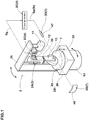
- Figure 1 is a perspective view of the projection image capture apparatus used in the observing method according to the present embodiment.
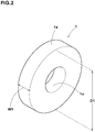
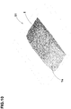
- Figure 2 is a perspective view of the elastic material in the present embodiment.
- the elastic material 1 is, for example, formed as a cylindrical rubber material whose outer peripheral surface 1s is formed in a circular shape.
- the elastic material 1 is provided in the center with a hole 1o penetrating in the thickness direction (axial direction).
- the outer diameter D1 of the elastic material 1 is set to be, for example, about 50 mm to 100 mm.
- the width w1 of the elastic material 1 is set to be, for example, about 15 mm to 30 mm.
- the projection image capture apparatus 2 is provided with a deforming means 2A for pressing the elastic material 1 onto a contacted surface 23, a contact base 2B having the contacted surface 23, a capture signal outputting means 2C, and a capturing means 2D.
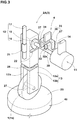
- Figure 3 is an enlarged perspective view showing a first pusher.
- the deforming means 2A is for the purpose of deforming the elastic material 1 in predetermined cycles by pressing it onto the contacted surface 23.
- the deformation means 2A in the present embodiment is formed as the first pusher 3 to make the elastic material 1 linearly reciprocate.
- the first pusher 3 includes an electric motor 11 having an output shaft 14 which rotates, a conversion device 12 which converts the rotational motion of the output shaft 14 to a linear reciprocating motion, and a holder 13 for holding the elastic material 1.
- the electric motor 11 in the present embodiment for example, an AC or DC electric motor is employed. As shown in Figure 1 , the electric motor 11 is supported by a L-shaped support frame 25 fixed to the contact base 2B. As shown in Figure 3 , the output shaft 14 extends horizontally and is rotated about a horizontal axis by the electric motor 11.
- the conversion device 12 includes a base portion 16, a rail portion 17, and a cam 18.
- the base portion 16 is, for example, formed in a rectangular parallelepiped shape extending in the up-down direction.
- the base portion 16 is provided on a side with a slide mechanism 21 that engages the rail portion 17. Further, the base portion 16 is provided on the other side with a follower portion 22 extending horizontally on the lower side of the cam 18 and contacting with the outer peripheral surface of the cam 18.
- the rail portion 17 extends in the up-down direction on one side of the base portion 16, and its upper end is fixed to the support frame 25 (shown in Figure 1 ). By such rail portion 17, the base portion 16 can be guided in the up-down direction through the slide mechanism 21.
- FIG 4 is an enlarged side view showing the cam 18 and the follower portion 22.
- the cam 18 is formed as a disc cam having a substantially ovoid shape whose distance L1 from its center to the outer peripheral surface is not constant.
- one end of the output shaft 14 of the electric motor 11 is fixed to the center of the cam 18. Accordingly, by the rotation of the output shaft 14, the cam 18 can be rotated about a horizontal axis.
- the holder 13 includes a horizontal plate 13a extending horizontally, and a pair of vertical plates 13b and 13b extending downward from both ends of the horizontal plate 13a.
- the holder 13 is formed in a substantially U-shaped in the front view.
- the upper end of the horizontal plate 13a is connected to the lower end of the base portion 16 of the conversion device 12 through a load cell 26 capable of detecting a load.
- the lower end sides of a pair of the vertical plates 13b, 13b are disposed on both sides of the elastic material 1.
- a pair of the vertical plates 13b, 13b are provided with a shaft portion 27 extending horizontally between a pair of the vertical plates 13b, 13b.
- the shaft portion 27 is fixed to the hole 1o of the elastic material 1 (shown in Figure 2 ). Thereby, the elastic material 1 is held rotatably around the horizontal axis.
- the elastic material 1 can be linearly reciprocated in the up-down direction through the holder 13.
- the compression deformation of the elastic material 1 toward the contacted surface 23 and relaxation of the compressive deformation are performed alternately. Therefore, the first pusher 3 can deform the elastic material 1 in predetermined cycles, while pressing it onto the contacted surface 23.
- the first pusher 3 in the present embodiment is configured as a vibrating device using an electric motor 11, but it is not limited thereto.
- the first pusher 3 for example, it may be configured as vibrating unit of an oil type or an electromagnetic type.
- the contact base 2B includes a road surface portion 45 provided in the upper surface with the contacted surface 23, and a lower supporting portion 46 for supporting the road surface portion 45.
- the road surface portion 45 is formed in a plate shape which is circular in a plan view.
- a simulated road surface where irregularities of the asphalt pavement are reproduced is preferably formed.
- the lower supporting portion 46 is formed in a plate shape which is rectangular in a plan view. To the lower supporting portion 46, a bottom side of the support frame 25 is fixed. Further, the lower supporting portion 46 is provided with a lifting means (not shown) for moving the road surface portion 45 in the up-down direction. By the lifting means, the road surface portion 45 is moved in the up-down direction relatively to the elastic material 1. Thereby, the load to be applied to the elastic material 1 can be adjusted.
- a rotating means 50 for rotating the first pusher 3 and the contacted surface 23 around the vertical axis through the support frame 25 and the lower supporting portion 46.
- Such rotating means 50 can move the elastic material 1 relatively to the capturing means 2D.
- the capture signal outputting means 2C is for the purpose of outputting a capture signal at a predetermined specific time point within one cycle.
- the capture signal outputting means 2C in the present embodiment includes the linear position detecting device 4, and the pulse generator 5.
- the linear position detecting device 4 is for the purpose of detecting a specific position in the linear reciprocating motion of the elastic material 1 (specific deformed state).
- a photo interrupter of a transmission type or a reflection type or the like can be applied.
- the linear position detecting device 4 is provided with a protrusion 32 which protrudes radially outwardly from the output shaft 14, a frame 33 which is disposed above the output shaft 14, a sensor 34 for detecting the protrusion 32, and an output portion (not shown) for outputting a detection signal Sg (shown in Figure 1 ).
- the protrusion 32 is formed in a cubic shape having a surface 32s intersecting the axial direction of the output shaft 14.
- the outer peripheral surface of the output shaft 14 is provided with at least one protrusion 32 (one in the present embodiment). Such protrusion 32 is rotated about a horizontal axis by the rotation of the output shaft 14.
- the frame 33 includes a horizontal plate 36 extending horizontally, and a pair of vertical plates 37, 37 extending from both ends of the horizontal plate 36 downwardly, and is formed in a substantially U-shaped in the front view. Further, the frame 33 is provided with a space 38 surrounded by the horizontal plate 36 and a pair of the vertical plates 37, 37. The frame 33 is secured to the support frame 25 (shown in Figure 1 ) so that the rotating protrusion 32 can pass through the space 38.
- the sensor 34 is, for example, configured as a laser sensor.
- laser is irradiated in parallel to the axial direction of the output shaft 14.
- the detection signal Sg (shown in Figure 1 ) is output from the output portion (not shown).
- the detection signal Sg is input to the pulse generator 5.
- the detection signal Sg is output from the output unit (not shown) at a time point when the specific position in the linear reciprocating motion of the elastic material 1 is detected.
- the specific position in the linear reciprocating motion of the elastic material 1 can be appropriately changed by changing the fixing position of the protrusion 32 in the circumferential direction of the output shaft 14.
- the pulse generator 5 is for the purpose of outputting the pulse signal Sp based on the detection signal Sg of the linear position detecting device 4.
- the detection signal Sg of the linear position detecting device 4 when the detection signal Sg of the linear position detecting device 4 is input, at least one (in the present embodiment, one) pulse signal Sp is output.
- the detection signal Sg is output by the linear position detecting device 4 on the detection of the specific position in the linear reciprocating motion of the elastic material 1. Accordingly, the pulse signal Sp is output at the specific position in the linear reciprocating motion of the elastic material 1 (specific time point in one cycle).
- the output pulse signal Sp is input to the capturing means 2D as a capture signal St.
- pulse signal Sp in the present embodiment TTL (5v-0v) is employed, but it is not limited thereto.
- Other pulse signal Sp for example, a single pulse or successive pulses may be employed.
- one pulse signal Sp is output by inputting the detection signal Sg, but it is not limited thereto. For example, it may be possible that successive pulse signals Sp are output during the detection signal Sg is not input, and the output of the successive pulse signals Sp is stopped only when the detection signal Sg is input.
- an X-ray camera 7 is included.
- the X-ray camera 7 in the present embodiment is a conventional CT (Computed Tomography) apparatus.
- the X-ray camera 7 includes an X-ray tube 47 for irradiating the elastic material 1 with X-ray, a detector 48 for detecting the X-ray transmitted through the elastic material 1, and a shutter trigger (not shown) for irradiating the X-ray from X-ray tube 47.
- the X-ray tube 47 and the detector 48 are arranged in a straight line with the first pusher 3 and the contact base 2B disposed therebetween. Further, in the present embodiment, the height of the x-ray tube 47 is adjusted so that the elastic material 1 and the contacted surface 23 are irradiated with the X-ray.
- the x-ray tube 47 and the detector 48 in the present embodiment are fixed immovably with respect to the first pusher 3 and the contact base 2B.
- the detector 48 includes a converter (not shown) for converting X-ray into photoelectrons, a phosphor (not shown) for converting photoelectrons into visible light, and a CCD camera (not shown) for capturing a visible light like a conventional detector,
- the capture signal St pulse signal Sp
- the shutter trigger not shown
- the X-ray from the X-ray tube 47 is irradiated for a period of 0.1 milliseconds to 100 milliseconds, for example.
- Figure 5 is a plan view showing a capture position P of the elastic material 1.
- the projection image of the elastic material 1 can be captured from a direction perpendicular to arbitrarily axis of the elastic material 1 (in the present embodiment, the vertical axis L3 extending vertically at the center of gravity of the elastic material 1). Further, in the capturing means 2D, as the first pusher 3 and the contacted surface 23 are rotated around the vertical axis by the rotating means 50 shown in Figure 1 , the projection image of the elastic material 1 can be captured at a plurality of capture positions P around the axis of the elastic material.
- FIG. 6 is a flowchart illustrating an example of the processing procedure of the observing method in the present embodiment.
- the elastic material 1 whose outer peripheral surface is formed in a circular shape as shown in Figure 2 is prepared (step S0).
- the projection image of the elastic material 1 is captured (projection image obtaining step S1).
- the projection image of at least a part of the elastic material 1 is captured at a plurality of capture positions P (shown in Figure 5 ) around the axis (in the present embodiment, the vertical axis L3) from a direction perpendicular to the axis of the elastic material 1.
- the capture position P in the present embodiment is set at a plurality of positions at predetermined intervals around the vertical axis L3 of the elastic material 1 between a capture start position Ps on one side of the elastic material 1 and a capture end position Pe on the other side of the elastic material 1.
- the X-ray camera 7 is positioned at a plurality of the capture positions P.
- the angle (narrow angle) formed between the capture start position Ps and the capture end position Pe is preferably set to be not more than 180 degrees.
- Figure 7 is a flowchart illustrating an example of the processing procedure of the projection image obtaining step S1 in the present embodiment.
- the X-ray camera 7 is positioned at the capture start position Ps (shown in Figure 5 ) (step S11).
- the first pusher 3 and the contact base 2B shown in Figure 1 are rotated around the vertical axis, and the x-ray camera 7 is arranged at the capture start position Ps.
- FIG. 8 is a flowchart illustrating an example of the processing procedure of the deforming step S12 in the present embodiment.
- step S121 the elastic material 1 is pressed onto the contacted surface 23 (step S121).
- step S121 a position M1 at which the above-mentioned distance L1 of the cam 18 becomes maximum (hereinafter, simply referred to as "maximum distance position of the cam") is set to the lowest point of the cam 18.
- the road surface portion 45 is moved in the up-down direction. Thereby, the elastic material 1 is pressed onto the contacted surface 23 (shown in Figure 1 ), and the load is set on the elastic material 1.
- the load set to the elastic material 1 becomes a maximum load at the time of deformation of the elastic material 1.
- the load of the elastic material 1 can be measured with the load cell 26 of the first pusher 3.
- step S122 by rotating the output shaft 14 (shown in Figure 3 ) of the electric motor 11, the elastic material 1 is deformed (step S122).
- step S122 as shown in Figures 4 (a) and 4 (b) , by the rotation of the output shaft 14 of the electric motor 11, the base portion 16 of the conversion device 12 is linearly reciprocated.
- step S122 by the linear reciprocating motion of the base portion 16 of the conversion device 12, the elastic material 1 is linearly reciprocated while being pressed onto the contacted surface 23. Thereby, compression deformation of the elastic material 1 toward the contacted surface 23, and, relaxation of the compressive deformation are performed alternately. Therefore, in the deformation step S12, based on the rotation of the electric motor 11, the elastic material 1 can be deformed in the predetermined cycles.
- the capture signal St (shown in Figure 1 ) is output at a predetermined specific time point in one cycle (the signal output step S13).
- the linear position detecting device 4 and the pulse generator 5 are used.
- the capture signal St (pulse signal Sp) is output at the position (time point) at which the compressive deformation of the elastic material 1 becomes maximized, of the one cycle of the linear reciprocating motion of the elastic material 1.
- the time point when the capture signal St is output (i.e., the specific position in the linear reciprocating motion of the elastic material 1) can be set as appropriate by changing the position of the protrusion 32 with respect to the circumferential direction of the output shaft 14, or, the position of the cam 18.
- the projection image of the elastic material 1 is captured (capturing step S14).
- the capturing step S14 at the time point when the capture signal St (pulse signal Sp) is input to the shutter trigger (not shown) of the X-ray camera 7, and the X-ray from the X-ray tube 47 is irradiated.
- the projection image of the elastic material 1 is captured at the specific position in the linear reciprocating motion of the elastic material 1 (in the present embodiment, the position in the linear reciprocating motion of the elastic material 1 at which the compressive deformation of the elastic material 1 becomes maximum).
- captured is the projection image including at least a part of the contact portion between the elastic material 1 and the contacted surface 23 onto which the elastic material 1 is pressed.
- the projection image of the elastic material 1 is stored in a computer (not shown) connected to the X-ray camera 7.
- step S15 it is judged whether the capturing of the elastic material 1 is completed at a plurality of predetermined capture positions P (shown in Figure 5 ) (step S15).
- step S15 if the capturing of the elastic material 1 is judged as being completed ("Y" in the step S15), then the subsequent three-dimensional image constructing step S2 is performed.
- the X-ray camera 7 is positioned at the next capture position P, and the deforming step S12 - the step S15 are performed again.
- the deforming step S12, the signal output step S13 and the capturing step S14 are performed at each of the capture positions P. Therefore, in the projection image obtaining step S1, even if the elastic material 1 is periodically deformed, at each of the capture positions P, it is always possible to capture the projection image in the specific state of the deformation (deformation at the specific moment).
- the decay time of the phosphor (not shown) of the detector 48 is set to 100 ms or less.
- the decay time of the phosphor is preferably nor more than 50 ms, more preferably not more than 10 ms. If the decay time of the phosphor is too short, the efficiency of the conversion of photoelectrons to visible light may be reduced. From this point of view, the decay time of the phosphor is preferably not less than 0.1 ms.
- the intensity of the X-ray is preferably not less than 10 10 , more preferably not less than 10 12 .
- a three-dimensional image of the elastic material 1 is constructed (three-dimensional image constructing step S2).
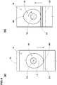
- Figure 9 is a three-dimensional image of the elastic material 1 and the contacted surface 23.
- Figure 10 is a three-dimensional image of the outer peripheral surface 1s of the elastic material 1 viewed from the under side.
- the three-dimensional image constructing step S2 in the present embodiment for example, according to the Convolution Back Projection method, by reversely projecting the projection images of the elastic material 1 captured at a plurality of the capture positions P (shown in Figure 5 ) as is conventionally done, the three-dimensional image 51 of the elastic material 1 can be constructed.
- a plurality of the projection images of the elastic material 1 are captured, in the projection image obtaining step S1, at the specific position in the linear reciprocating motion of the elastic material 1, (in the present embodiment, at the position in the linear reciprocating motion of the elastic material 1 at which the compressive deformation of the elastic material 1 becomes maximum). Therefore, in the three-dimensional image constructing step S2, a three-dimensional image 51 under the specific state of deformation (deformation moment) can be obtained.
- the three-dimensional image 51 of the elastic material 1 is observed (step S3).
- the three-dimensional image 51 by observing the three-dimensional image 51, it is possible to directly observe the specific deformed state (deformation moment) of the actual elastic material 1 which is being deformed periodically. Therefore, in the observing method in the present embodiment, performance of the elastic material 1 can be assessed accurately. Further, based on the deformed state of the elastic material 1, it is possible, for example, to create a rubber model for use in a simulation based on the finite element method, and define boundary conditions. Thus, the observing method in the present embodiment is useful for improving he simulation accuracy.
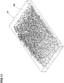
- Figure 11 is a three-dimensional image 51 of the elastic material 1 containing marker particles 52.
- the marker particles 52 in the present embodiment for example, alumina particles having a diameter of about 40 micrometers are used. Such marker particles 52 are displayed emphatically in the three-dimensional image 51, and the deformed shape of the elastic material 1 can be accurately measured. Further, the strain distribution of the elastic material 1 can be obtained from the positional information on the marker particles 52 based on a digital image correlation method.
- the marker particles 52 are not limited to alumina particles. Other marker particles 52 can be employed as appropriate as far as the density is more than the rubber (e.g., barium sulfate, etc.),
- the content of the marker particles 52 is 1 to 100 parts by mass. Incidentally, if the content of the marker particles 52 is less than 1 parts by mass, there is possibility that a specific deformed state (deformation moment) of the elastic material 1 can not be accurately observed. If the content of the marker particles 52 is more than 100 parts by mass, as physical properties of the elastic material 1 are changed significantly, there is possibility that the performance of the elastic material 1 can not be accurately evaluated. From this point of view, the content of the marker particles 52 is preferably not less than 5 parts by mass, more preferably not less than 10 parts by mass. The content of the marker particles 52 is preferably not more than 70 parts by mass, more preferably not more than 50 parts by mass.
- the deformation means 2A is constructed by the first pusher 3 to linearly reciprocate the elastic material 1. But it is not limited thereto.
- the deforming means 2A may be constructed by a second pusher which rotates the outer peripheral surface 1s of the elastic material 1 while pressing it onto the contacted surface 23.
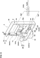
- Figure 12 is a perspective view of the projection image capture apparatus in the present embodiment.
- Figure 13 is an enlarged perspective view of the second pusher 53.
- the projection image capture apparatus 2 in the present embodiment includes a deforming means 2A composed of the second pusher 53, the contact base 2B, the capture signal outputting means 2C, and the capturing means 2D (not shown).
- the capturing means 2D is of the same structure as the capturing means 2D in the former embodiment (shown in Figure 1 ).
- the second pressing tool 53 is provided with a holder 13 for holding the elastic material 1, a first rotating means 54 for rotating the elastic material 1, and an adjuster 55 for changing the distance between the holder 13 and the contacted surface 23.
- the holder 13 is of the same structure as the holder 13 in the former embodiment (shown in Figure 3 ).
- the second pusher 53 is provided with a base portion 16 extending in the up-down direction similarly to the first pusher 3 shown in Figure 3 .
- the first rotating means 54 for example, an AC or DC electric motor is employed.
- the first rotating means 54 in the present embodiment is disposed above the first rotating means 54, and is supported by a frame 59 fixed to the base portion 16. Further, the first rotating means 54 is provided with the first output shaft 54a rotatable about a horizontal axis.
- the other end of the first output shaft 54a (on the opposite side to the first rotating means 54 in the axial direction of the first output shaft 54a) is supported by a pair of the vertical plates 13b, 13b of the holder 13, rotatably around a horizontal axis. Further, the first output shaft 54a is fixed to the hole 1o of the elastic material 1 (shown in Figure 2 ). Thus, by rotating the first output shaft 54a, the elastic material 1 can be rotated about a horizontal axis. Further, the first output shaft 54a, may be provided with a torque meter 57 for measuring the torque of the first output shaft 54a.
- the adjuster 55 includes a rail portion 17, and a moving means 56 for moving the base portion 16 in the up-down direction.
- the rail portion 17 extends in the up-down direction on one side of the base portion 16 similarly to the rail portion 17 in the former embodiment (shown in Figure 2 ).
- the upper end of the rail portion 17 is fixed to the support frame 58 fixed to the rotating means 50 (shown in Figure 12 ).
- the rail portion 17 is engaged with the slide mechanism 21 of the base portion 16.
- the base portion 16 can be guided in the up-down direction by such rail portion 17.
- the moving means 56 includes a threaded shaft 56a extending in the up-down direction.
- the threaded shaft 56a is screwed to the support frame 58.
- the lower end of the threaded shaft 56a is attached to the upper end of the base portion 16 through a rotary joint 68 which is rotatable about a vertical axis.
- the upper end of the threaded shaft 56a is provided with a handle portion 67 for rotating the threaded shaft 56a about the vertical axis
- the threaded shaft 56a is moved in the up-down direction relative to the support frame 58.
- the threaded shaft 56a is moved in the up-down direction.
- the holder 13 fixed to the base portion 16 is moved in the up-down direction.
- the distance between the holder 13 and the contacted surface 23 (the distance between the contacted surface 23 and the elastic material 1 held by the holder 13) can be varied. Further, since the frame 59 is moved in the up-down direction with the vertical movement of the base portion 16, the first rotary unit 54 fixed to the frame 59 and the undermentioned first frame 33a of the first rotational position detecting device 63 are moved in the up-down direction together with the elastic material 1.
- the contact base 2B in the present embodiment is configured to include a drum 61 and a second rotating means 60.
- the drum 61 is formed in a cylindrical shape rotatable about a horizontal axis.
- the contacted surface 23 onto which the outer peripheral surface 1s of the elastic material 1 is pressed, is formed in the outer peripheral surface 61s of the drum 61. It is desirable that, in the contacted surface 23, for example, a plurality of grooves 62 (shown in Figure 15 ) extending in the drum's axial direction are arranged in the drum's circumferential direction at intervals. Further, the contacted surface 23 may be provided with a road surface simulating irregularities of the asphalt pavement.
- the second rotating means 60 for example, an AC or DC electric motor is used.
- the second rotating means 60 is fixed to the support frame 58. Further, the second rotating means 60 is provided with a second output shaft 60a rotatable about a horizontal axis.
- the opposite side end of the second output shaft 60a (the opposite side of the second rotating means 60 in the axial direction of the second output shaft 60a) is supported by the support frame 58 rotatably about a horizontal axis. Further, the second output shaft 60a is fixed to the axis of the drum 61. Thus, by rotating the second output shaft 60a, the drum 61 can be rotated about a horizontal axis. Accordingly, the second rotating means 60 can move the contacted surface 23 of the drum 61 in the circumferential direction.
- the second output shaft 60a is rotated in the reverse direction of the first output shaft 54a of the first rotating means 54.
- the drum 61 can rotate the elastic material 1.
- the slip angle between the moving direction of the contacted surface 23 of the drum 61 and the moving direction of the outer peripheral surface 1s of the elastic material 1 is set to zero.
- the outer diameter D3 of the drum 61 can be set arbitrarily.
- the outer diameter D3 of the drum 61 is set to be an integral multiple of the outer diameter D1 (shown in Figure 2 ) of the elastic material 1. Accordingly, when the slip ratio of the elastic material 1 and the contacted surface 23 is zero, it is possible to always contact a specific position of the elastic material 1 with a specific position of the drum 61.
- the outer diameter D3 of the drum 61 is set to be the same as the outer diameter D1 of the elastic material 1.
- the rotational speed of the first rotating means 54 and the rotational speed of the second rotating means 60 may be set arbitrarily. For example, if the outer diameter D3 of the drum 61 is more than the outer diameter D1 (shown in Figure 2 ) of the elastic material 1, the rotational speed of the first rotating means 54 may be set to be higher than the rotational speed of the second rotating means 60 so that the slip ratio of the elastic material 1 and the drum 61 is zero. Further, by respectively setting the rotational speed of the first rotating means 54 and the rotational speed of the second rotating means 60, the deformation of a tread rubber of a tire at the time of acceleration or deceleration is artificially reproduced.
- a flat-belt (not shown) may be used instead of the drum 61 in the present embodiment. According to such flat belt, the shape of the contact portion between the elastic material 1 and the contacted surface 23 becomes flat, and a tire during running can be more accurately reproduced.
- the rotating means 50 for rotating the second pusher 53 and the contact base 2B around the vertical axis through the support frame 58.
- Such rotating means 50 can move the elastic material 1 and the contacted surface 23, relatively to the capturing means 2D (x-ray camera 7) shown in Figures 1 and 5 .
- the first rotational position detecting device 63 As shown in Figures 12 and 13 , in the capture signal outputting means 2C in the present embodiment, the first rotational position detecting device 63, the second rotational position detecting device 64 and the pulse generator 5 are included.
- the first rotational position detecting device 63 is for the purpose of detecting a specific position in the rotation of the elastic material 1.
- the first rotational position detecting device 63 in the present embodiment includes a first protrusion 32a protruding radially outward from the first output shaft 54a, the first frame 33a disposed above the first output shaft 54a, a first sensor 34a for detecting the first protrusion 32a, and the output unit (not shown) for outputting a detection signal Sg1 (shown in Figure 12 ).
- the first protrusion 32a passing through the space 38a of the first frame 33a can be detected by the first sensor 34a. Further, when the passage of the first protrusion 32a is detected, as shown in Figure 12 , the detection signal Sg1 is output from the output unit (not shown) towards the pulse generator 5.
- the outer peripheral surface 1s of the elastic material 1 and the first protrusion 32a are rotated at the same cycle. Accordingly, in the first rotational position detecting device 63, by the detection of the first projecting portion 32a, the specific position of the outer peripheral surface 1s of the elastic material 1 can be detected.
- the second rotational position detecting device 64 is for the purpose of detecting a specific position in the movement of the contacted surface 23.
- the second rotational position detecting device 64 includes a second protrusion 32b protruding radially outwardly from the second output shaft 60a, a second frame 33b disposed below the second output shaft 60a, a second sensor (not shown) for detecting the second protrusion 32b, and an output unit (not shown) for outputting a detection signal Sg 2.
- the second protrusion 32b passing through the space 38b of the second frame 33b can be detected by the second sensor (not shown). Further, when the passage of the second protrusion 32b is detected, the detection signal Sg2 is output from the output unit (not shown) toward the pulse generator 5.
- the outer peripheral surface 61s of the drum 61 and the second protrusion 32b are rotated at the same cycle. Therefore, in the second rotational position detecting device 64, by the detection of the second protrusion 32b, the specific position of the outer peripheral surface 61s of the drum 61 can be detected.
- the pulse signal Sp is output by simultaneously inputting the detection signal Sg1 of the first rotational position detecting device 63 and the detection signal Sg2 of the second rotational position detecting device 64.
- the detection signal Sg1 is output by the detection of the specific position on the outer peripheral surface 1s of the elastic material 1.
- the detection signal Sg2 is output by the detection of the specific position on the outer peripheral surface of the drum 61.
- the pulse signal Sp (capture signal St) can be output at the time point (specific time point in one cycle) when the specific position of the outer peripheral surface 1s of the elastic material 1 contacts with the specific position of the outer peripheral surface 61s of the drum 61.
- the first protrusion 32a is disposed in the space 38a of the first frame 33a (shown in Figure 13 ), and the second protrusion 32b is disposed in the space 38b of the second frame 33b. Accordingly, the pulse signal Sp (capture signal St) can be output at a time point when the outer peripheral surface 1s of the elastic material 1 contacts with the outer peripheral surface 61s of the drum 61 at the contacting position in the initial state.
- a projection image including at least part of the contact portion is captured from a direction perpendicular to the axis of the elastic material 1 (the vertical axis L3 in the present embodiment) at a plurality of capture positions P around the axis similarly to the observing method in the former embodiment shown in Figures 1 and 5 .
- the elastic material 1 whose outer peripheral surface is circular is used.
- the X-ray camera 7 as the capturing means 2D is positioned at the capture start position Ps shown in Figure 5 (step S11).
- the second pusher 53 and the contact base 2B are rotated around the vertical axis by the rotating means 50, and the X-ray camera 7 is positioned at to the capture start position Ps.
- the elastic material 1 is deformed in the predetermined cycles (deforming step S12).
- the second pusher 53 and the contact base 2B shown in Figures 12 and 13 are used.
- Figure 14 is a flowchart illustrating an example of the processing procedure of the deforming step S12 in the present embodiment.
- the elastic material 1 is pressed onto the contacted surface 23 (step S421).
- the first protrusion 32a is disposed in the space 38a of the first frame 33a.
- the second projection portion 32b is disposed in the space 38b of the second frame 33b.
- the moving means 56 of the adjuster 55 the base portion 16 of the second pusher 53 is moved up and down.
- the load applied to the elastic material 1 may be defined to be equal to the load applied to the actual tire (ground contact pressure) for example.
- the first output shaft 54a of the second pusher 53 and the second output shaft 60a of the contact base 2B are rotated in the opposite directions to each other (step S422).
- the outer peripheral surface 1s of the elastic material 1 can be rotated (deformed) while being pressed onto the contacted surface 23. Therefore, in the deforming step S42, based on the rotation of the first rotating means 54 and the second rotating means 60, the elastic material 1 can be deformed in predetermined cycles.
- the capture signal St is output at a predetermined specific time point in the one cycle (the signal output step S13).
- the signal output step S13 in the present embodiment uses the capture signal outputting means 2C including the first rotational position detecting device 63, the second rotational position detecting device 64, and the pulse generator 5.
- the detection signals Sg1, Sg2 are output toward the pulse generator 5. Further, in the pulse generator 5 in the present embodiment, when the detection signal Sg1 of the first rotational position detecting device 63 and the detection signal Sg2 of the second rotational position detecting device 64 are input at the same time, the pulse signal Sp is output.
- the pulse signal Sp (capture signal St) can be output at the time point (specific time point in one cycle) when the specific position of the outer peripheral surface 1s of the elastic material 1 comes into contact with the specific position of the outer peripheral surface 61s of the drum 61.
- the time point when the capture signal St is output can be appropriately adjusted by changing the fixed positions of the first protrusion 32a and the second protrusion 32b.
- the projection image of the elastic material 1 is captured (capture step S14).
- the projection image of the elastic material 1 is captured at the specific position of the elastic material 1 during rotating (in the present embodiment, the time point when the specific position of the outer peripheral surface 1s of the elastic material 1 comes into contact with the specific position of the outer peripheral surface 61s of the drum 61).
- the capturing step S14 in the present embodiment there is captured the projection image including at least part of the contact portion between the elastic material 1 and the contacted surface 23 onto which the elastic material 1 is pressed.
- the projection image of the elastic material 1 is stored in a computer (not shown)connected to the X-ray camera 7 shown in Figure 1 .
- step S15 it is judged whether the capturing of the elastic material 1 is completed at a plurality of the predetermined capture positions P (shown in Figure 5 ) (step S15).
- step S15 if the capturing of the elastic material 1 is judged as being completed ("Y" in the step S15), then the subsequent three-dimensional image constructing step S2 is performed.
- the x-ray camera 7 is positioned at the next capture position P (step S16), and the deforming step S12 - the step S15 are performed again.
- the deforming step S12, the signal output step S13, and the capturing step S14 are performed at each of the capture positions P. Accordingly, in the projection image obtaining step S1 in the present embodiment, it is always possible to capture the projection image of the specific state of deformation (deformation moment) at each of the capture positions P.
- a three-dimensional image of the elastic material 1 is constructed (three-dimensional image constructing step S2).
- Figure 15 is a three-dimensional image 70 of the elastic material 1 and the drum 61.
- the three-dimensional image 70 of the elastic material 1 can be constructed by the same method as in the former embodiment.
- the three-dimensional image 70 under a specific deformed state in the present embodiment, the three-dimensional image including concavity and convexity existing at specific positions on the outer peripheral surface 61s of the drum 61 (the contacted surface 23), and the elastic material deformed by the concavity and convexity
- the three-dimensional image 70 under a specific deformed state in the present embodiment, the three-dimensional image including concavity and convexity existing at specific positions on the outer peripheral surface 61s of the drum 61 (the contacted surface 23), and the elastic material deformed by the concavity and convexity
- a three-dimensional image 70 of the elastic material 1 is observed (step S3).
- a particular deformation (deformation moment) of the elastic material 1 which is rolling on the contacted surface 23 can be directly observed. Therefore, in the observing method in the present embodiment, performance of the elastic material 1 can be assessed accurately.
- the elastic material 1 contains marker particles 52 (shown in Figure 11 ) as in the former embodiment, in order to emphatically capture the three-dimensional image 70.
- the elastic material 1 contains marker particles 52 (shown in Figure 11 ) as in the former embodiment, in order to emphatically capture the three-dimensional image 70.
- the slip angle between the moving direction of the contacted surface 23 of the drum 61 and the moving direction of the outer peripheral surface 1s of the elastic material 1 is set to zero, but it is not limited thereto.
- a slip angle setting means for setting a slip angle to the elastic material 1 rolling on the contacted surface 23.
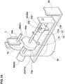
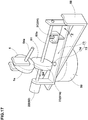
- Figure 16 is a perspective view showing the slip angle setting means.
- Figure 17 is a perspective view showing a state where a slip angle is set to the elastic material by the slip angle setting means of Figure 16 .
- the slip angle setting means 72 in the present embodiment is, for example, provided with a support base 73 and a supporting shaft 74.
- the support base 73 includes a horizontal plate 73a extending horizontally and a pair of vertical plates 73b, 73b extending upwardly from both ends of the horizontal plate 73a, and is formed in a substantially U-shaped in the front view.
- the second rotating means 60 is fixed to one of the vertical plates 73b. Further, by a pair of the vertical plates 73b, 73b, the second output shaft 60a to which the drum 61 is fixed, is supported rotatably about a horizontal axis. In such support base 73, the drum 61 can be rotated about the horizontal axis by the rotation of the second rotating means 60. Further, to the support base 73, the second frame 33b of the second rotational position detecting device 64, and the second sensor (not shown) are fixed.
- the supporting shaft 74 extends in the up-down direction.
- the support base 73 can be supported rotatably around the vertical axis with respect to the support frame 58.
- the moving direction of the outer peripheral surface 1s of the elastic material 1 is fixed.
- the support base 73 is rotated around the support shaft 74 in the arrow Z direction with reference to the support frame 58.
- the drum 61 is provided with an attitude angle, and a relative slip angle SA is given between the elastic material 1 and the drum 61.
- the width of the drum 61 is set to be greater than the width w1 (shown in Figure 2 ) of the elastic material 1.
- FIG. 18 is a flowchart illustrating an example of the processing procedure of the deforming step S12 in the present embodiment.
- the second pusher 53 shown in Figures 12 and 13
- the contact base 2B the contact base 2B
- the slip angle setting means 72 are used.
- the deforming step S12 first, as shown in Figure 16 , the elastic material 1 is pressed onto the contacted surface 23 (step S421).
- the processing procedure of the step S421 is the same as the processing procedure of the step S421 of the former embodiment.
- a slip angle SA (shown in Figure 17 ) is set to the elastic material 1 (step S423).
- the support base 73 is rotated around the support shaft 74. Accordingly, the slip angle SA is set to the elastic material 1.
- the slip angle SA may be set as appropriate. In the present embodiment, the slip angle SA is determined to be equal to the slip angle imparted to the actual tire.
- the first output shaft 54a of the second pusher 53 and the second output shaft 60a of the contact base 2B are rotated in the opposite directions to each other (step S422).
- the elastic material 1 in a state in which the slip angle SA has been set to the elastic material 1, the elastic material 1 can be rotated (deformed) while the outer peripheral surface 1s of the elastic material 1 is pressed onto the contacted surface 23. Therefore, in the deforming step S42, based on the rotation of the first rotating means 54 and the second rotating means 60, the elastic material 1 can be deformed in predetermined cycles.
- the observing method in the present embodiment in the same manner as the observing method in the former embodiment, at each of the capture positions P (shown in Figure 5 ), the projection image of the elastic material 1 is captured, and the three-dimensional image of the elastic material 1 is observed.
- the three-dimensional image of the elastic material 1 can be observed in detail in a state approximate to the tire during running with the slip angle SA applied, therefore, the performance of the elastic material 1 can be accurately assessed.
- the elastic material 1 contains marker particles 52 (shown in Figure 11 ) in order to emphatically capture the three-dimensional image 70 as in the former embodiment.
- the slip angle SA is given to the elastic material 1 by rotating the support table 73, but it is not limited thereto.
- the elastic material 1 is pressed onto the dry contacted surface 23, but it is not limited thereto.
- a fluid supply means for supplying a fluid toward the contact portion between the elastic material 1 and the contacted surface 23.
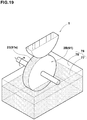
- Figure 19 is a perspective view of the fluid supply means 76.
- the fluid supply means 76 includes a water tank 78 in which the fluid 77 is stored.
- the water tank 78 is disposed beneath the drum 61 so that at least a part of the contacted surface 23 of the drum 61 is immersed in the fluid 77. Thereby, the fluid 77 is supplied to the contacted surface 23 of the drum 61 by rotating the drum 61 with the second rotating means 60 (shown in Figure 16 ).
- a step of supplying the fluid 77 between the elastic material 1 and the contacted surface 23, is carried out in the deforming step S12, prior to (or at the same time) the step S121 or step S421 of pressing the elastic material 1 onto the contacted surface 23.
- the capturing step S14 therefore, it is possible to capture the projection image of the elastic material 1 with the fluid 77 interposed between the elastic material 1 and the contacted surface 23.
- Figure 20 is a three-dimensional image 71 of the elastic material 1 and the contacted surface 23 supplied with the fluid 77.
- the fluid 77 for example, water, oil, or a solution containing a contrast agent made up of a substance such as barium or iodine can be used.
- the fluid 77 is supplied by the water tank 78 for storing the fluid 77, but it is not limited thereto.
- the elastic material 1 is a cylindrical rubber material, but it is not limited thereto.
- the elastic material 1 may be, for example, a rubber material formed in a rectangular shape, or a tire for use in automobiles.
- the three-dimensional image of working Example 1 is shown in Figures 9 and 10 .
- the three-dimensional image of working Example 2 is shown in Figure 11 .
- the three-dimensional image of working Example 3 is shown in Figure 20 .
- the three-dimensional image 51 was emphatically displayed in comparison with the observing method of working Example 1. Therefore, in the observing method of working Example 2, the performance of the elastic material was assessed accurately in comparison with the observing method of working Example 1. Also, in the observing method of working Example 3, the three-dimensional image of the elastic material rolling on the contacted surface was obtained. Therefore, in the observing method of working Example 3, the rolling performance of the elastic material was accurately assessed.
- Figure 21 is a cross-section of the three-dimensional image constructed according to working Example 4.
- Figure 22 is another cross-section of the three-dimensional image constructed according to working Example 4.
Landscapes
- Physics & Mathematics (AREA)
- General Physics & Mathematics (AREA)
- Health & Medical Sciences (AREA)
- Chemical & Material Sciences (AREA)
- Pathology (AREA)
- Immunology (AREA)
- General Health & Medical Sciences (AREA)
- Biochemistry (AREA)
- Analytical Chemistry (AREA)
- Life Sciences & Earth Sciences (AREA)
- Engineering & Computer Science (AREA)
- Theoretical Computer Science (AREA)
- Radiology & Medical Imaging (AREA)
- Pulmonology (AREA)
- Nuclear Medicine, Radiotherapy & Molecular Imaging (AREA)
- Electromagnetism (AREA)
- Analysing Materials By The Use Of Radiation (AREA)
Claims (14)
- Procédé pour observer une déformation d'un matériau élastique (1) incluant du caoutchouc ou un élastomère, comprenant :une étape (S0) consistant à préparer le matériau élastique (1) dont la surface périphérique extérieure (1s) est formée sous une forme circulaire,une étape d'obtention d'image en projection (S1) consistant à capturer une image en projection d'au moins une partie du matériau élastique (1), depuis une direction perpendiculaire à un axe arbitraire du matériau élastique (1), à une pluralité de positions de capture (P) autour de l'axe,une étape de construction d'image tridimensionnelle (S2) consistant à construire une image tridimensionnelle du matériau élastique (1) à partir des images en projection capturées à la pluralité de positions de capture (P) en projetant en sens inverse les images en projection, etune étape d'observation (S3) de l'image tridimensionnelle construite,caractérisé en ce quel'étape d'obtention d'image en projection (S1) comprend :
une étape de déformation (S12) consistant à déformer le matériau élastique (1) en cycles prédéterminés, l'étape de déformation (S12) comprenant :une opération consistant à mettre en rotation la surface périphérique extérieure circulaire (1s) du matériau élastique (1) tout en pressant sur une surface de contact (23),une opération consistant à mettre en rotation un tambour cylindrique (61), de sorte que la surface de contact (23) est formée dans la surface périphérique extérieure (61s) du tambour (61), etune opération (s423) consistant à fixer un angle de glissement entre la direction de déplacement de la surface de contact (23) du tambour (61) et la direction de déplacement de la surface périphérique extérieure (1s) du matériau élastique (1),une opération de sortie de signal (s13) consistant à sortir un signal de capture à un instant spécifique prédéterminé pendant un cycle, etune opération de capture (s14) pour capturer l'image en projection du matériau élastique (1) sur la base du signal de capture, etl'étape de déformation (s12), l'opération de sortie de signal (s13) et l'opération de capture (s14) sont exécutées à chacune des positions de capture. - Procédé pour observer une déformation d'un matériau élastique selon la revendication 1, dans lequel
l'étape de déformation (s12) comprend une opération consistant à mettre le matériau élastique (1) en va-et-vient linéairement tout en étant pressée sur la surface de contact (23). - Procédé pour observer une déformation d'un matériau élastique selon la revendication 2, dans lequel
l'opération de sortie de signal (s13) comprend une opération consistant à sortir le signal de capture en détectant une position spécifique dans le mouvement en va-et-vient linéaire du matériau élastique (1). - Procédé pour observer une déformation d'un matériau élastique selon la revendication 1, dans laquelle
l'opération de sortie de signal (s13) comprend une opération consistant à sortir le signal de capture en détectant une position spécifique du matériau élastique pendant la rotation. - Procédé pour observer une déformation d'un matériau élastique selon l'une quelconque des revendications 1 à 4, dans lequel
l'opération de capture (s14) comprend une opération consistant à capturer l'image en projection incluant au moins une partie de la portion de contact entre le matériau élastique et la surface de contact contre laquelle le matériau élastique est pressé. - Procédé pour observer une déformation d'un matériau élastique selon l'une quelconque des revendications 1 à 5, dans lequel
l'étape de déformation (s12) comprend en outre une opération consistant à fournir un fluide entre le matériau élastique (1) et la surface de contact (23) contre laquelle le matériau élastique est pressé. - Appareil (2) adapté pour déformer un matériau élastique (1) incluant du caoutchouc ou un élastomère et adapté pour capturer une image en projection du matériau élastique (1) en accord avec la revendication de procédé 1, dans lequel le matériau élastique (1) a une surface périphérique extérieure circulaire (1s), caractérisé par
un moyen de déformation (2A) adapté pour déformer le matériau élastique (1) dans des cycles prédéterminés en le pressant contre une surface de contact (23), le moyen de déformation (2A) comprenant un poussoir (53) adapté pour mettre en rotation la surface circonférentielle extérieure (1s) du matériau élastique (1) tout en la pressant contre la surface de contact (23),
une base de contact (2B) comprenant un tambour cylindrique (61) et un moyen de rotation (60), le tambour cylindrique (61) ayant la surface de contact (23) formée dans la surface périphérique extérieure (61s) du tambour (61), et le moyen de rotation (60) étant adapté pour déplacer la surface de contact (23),
un moyen de fixation d'angle de glissement (72) adapté pour fixer un angle de glissement (5A) entre la direction de déplacement de la surface de contact (23) du tambour (61) et la direction de déplacement de la surface périphérique extérieure (1s) du matériau élastique (1),
un moyen de sortie de signal de capture (2C) adapté pour sortir un signal de capture (St) à un instant spécifique prédéterminé pendant un cycle, et
un moyen de capture (2D) adapté pour capturer une image en projection d'au moins une partie du matériau élastique (1), depuis une direction perpendiculaire à un axe arbitraire du matériau élastique (1), à une pluralité de positions de capture (P) autour de l'axe, sur la base du signal de capteur (St). - Appareil selon la revendication 7, dans lequel
le moyen de sortie de signal de capture (2C) comprend
un dispositif de détection de position (4) adapté pour détecter une position spécifique dans le mouvement de va-et-vient linéaire du matériau élastique (1), et
un générateur d'impulsion (5) adapté pour sortir un signal d'impulsion (Sp) sur la base d'un signal de détection du dispositif de détection de position (4). - Appareil selon la revendication 7, dans lequel le poussoir (53) comprend
un moyen de maintien (13) adapté pour maintenir le matériau élastique (1),
un premier moyen de rotation (54) adapté pour mettre le matériau élastique (1) en rotation, et
un moyen d'ajustement (55) adapté pour changer la distance entre le moyen de maintien (13) et la surface de contact (23). - Appareil selon la revendication 7, dans lequel
une surface routière simulée est formée dans la surface de contact (23). - Appareil selon la revendication 7, dans lequel le moyen de sortie de signal de capture (2C) comprend
un premier dispositif de détection de position en rotation (63) adapté pour détecter une position spécifique du matériau élastique (1) pendant une rotation,
un second dispositif de détection de position de rotation (64) adapté pour détecter une position spécifique de la surface de contact (23) pendant un déplacement, et
un générateur d'impulsion (5) adapté pour sortir un signal d'impulsion sur la base d'un signal de détection (Sg1) du premier dispositif de détection de position en rotation (63), et un signal de détection (Sg2) du second dispositif de détection de position de rotation (64). - Appareil selon l'une quelconque des revendications 7 à 11, dans lequel
le moyen de capture (2D) comprend une caméra à rayons X (7) ayant un déclencheur d'obturateur, et le signal de capture est injecté dans le déclencheur d'obturateur. - Appareil selon l'une quelconque des revendications 7 à 12, qui comprend en outre
un moyen d'alimentation en fluide (76) adapté pour alimenter un fluide jusqu'à une portion de contact entre le matériau élastique (1) et la surface de contact (23). - Appareil selon l'une quelconque des revendications 7 à 12, dans lequel le matériau élastique (1) contient des particules de marquage (52).
Applications Claiming Priority (3)
| Application Number | Priority Date | Filing Date | Title |
|---|---|---|---|
| JP2013237157A JP6182055B2 (ja) | 2013-11-15 | 2013-11-15 | 弾性材料の変形の観察方法 |
| JP2014131683A JP6412348B2 (ja) | 2014-06-26 | 2014-06-26 | 弾性材料の変形の観察方法及び投影像撮影装置 |
| PCT/JP2014/079419 WO2015072387A1 (fr) | 2013-11-15 | 2014-11-06 | Procédé de suivi de la déformation d'un matériau élastique et dispositif d'imagerie pour image de projection de matériau élastique |
Publications (3)
| Publication Number | Publication Date |
|---|---|
| EP3062091A1 EP3062091A1 (fr) | 2016-08-31 |
| EP3062091A4 EP3062091A4 (fr) | 2017-06-28 |
| EP3062091B1 true EP3062091B1 (fr) | 2020-09-23 |
Family
ID=53057323
Family Applications (1)
| Application Number | Title | Priority Date | Filing Date |
|---|---|---|---|
| EP14862786.2A Active EP3062091B1 (fr) | 2013-11-15 | 2014-11-06 | Procédé de suivi de la déformation d'un matériau élastique et dispositif d'imagerie pour image de projection de matériau élastique |
Country Status (3)
| Country | Link |
|---|---|
| US (1) | US10274438B2 (fr) |
| EP (1) | EP3062091B1 (fr) |
| WO (1) | WO2015072387A1 (fr) |
Families Citing this family (12)
| Publication number | Priority date | Publication date | Assignee | Title |
|---|---|---|---|---|
| CN104634589B (zh) * | 2015-02-11 | 2017-09-29 | 中信戴卡股份有限公司 | 一种用于模拟路面的转鼓 |
| WO2017073493A1 (fr) | 2015-10-27 | 2017-05-04 | 住友ゴム工業株式会社 | Bandage pneumatique et composition de caoutchouc réticulé |
| CN108349313B (zh) | 2015-10-27 | 2020-10-27 | 住友橡胶工业株式会社 | 充气轮胎和交联橡胶组合物 |
| EP3348426B1 (fr) | 2015-10-27 | 2020-09-02 | Sumitomo Rubber Industries, Ltd. | Bandage pneumatique et composition de caoutchouc réticulé |
| CN107843218B (zh) * | 2016-09-20 | 2021-06-01 | 香港理工大学 | 实时检测物体的多处结构变形或位移的方法与装置 |
| JP2018179882A (ja) * | 2017-04-19 | 2018-11-15 | 横浜ゴム株式会社 | タイヤx線検査システム、タイヤx線検査方法およびタイヤ支持装置 |
| JP6959849B2 (ja) * | 2017-12-07 | 2021-11-05 | Toyo Tire株式会社 | 接地面観察方法 |
| JP7180996B2 (ja) * | 2018-05-07 | 2022-11-30 | Toyo Tire株式会社 | タイヤ用荷重付与装置及びタイヤ用検査装置 |
| EP3814758A1 (fr) * | 2018-06-29 | 2021-05-05 | Universiteit Antwerpen | Inspection d'article par sélection dynamique d'angle de projection |
| US11733181B1 (en) * | 2019-06-04 | 2023-08-22 | Saec/Kinetic Vision, Inc. | Imaging environment testing fixture and methods thereof |
| CN110389044B (zh) * | 2019-07-12 | 2020-12-01 | 山东润通橡胶有限公司 | 一种汽车轮胎路面模拟智能检测装置 |
| CN113819863B (zh) * | 2021-10-08 | 2022-08-12 | 中国科学院国家授时中心 | 一种变形监测方法及系统 |
Citations (1)
| Publication number | Priority date | Publication date | Assignee | Title |
|---|---|---|---|---|
| JPH06218844A (ja) * | 1993-01-28 | 1994-08-09 | Toshiba Corp | タイヤ用ct装置 |
Family Cites Families (22)
| Publication number | Priority date | Publication date | Assignee | Title |
|---|---|---|---|---|
| US3883744A (en) * | 1971-11-23 | 1975-05-13 | Horst Steffel | Machines for examining pneumatic tires |
| US3826919A (en) * | 1972-09-08 | 1974-07-30 | Westinghouse Electric Corp | X-ray tire inspection apparatus |
| US3807226A (en) * | 1972-11-29 | 1974-04-30 | Department Of Transportation | Non-linear amplification technique for improving signal to noise contrast |
| DE3546149A1 (de) * | 1984-12-28 | 1986-07-17 | Kabushiki Kaisha Toshiba, Kawasaki, Kanagawa | Reifenbelastungstest-ct-abtaster |
| US4813062A (en) * | 1986-08-13 | 1989-03-14 | Milliken Research Corporation | Radio-opaque marker and method |
| US4839914A (en) * | 1987-06-10 | 1989-06-13 | Curry Leonard O | Portable tire X-ray apparatus and method |
| US5861454A (en) * | 1993-09-10 | 1999-01-19 | Hyperion Catalysis Int'l | Rubber composition containing carbon fibrils and a pneumatic tire |
| JP2955165B2 (ja) * | 1993-11-05 | 1999-10-04 | 東芝エフエーシステムエンジニアリング株式会社 | 断層撮影装置 |
| EP1043578B1 (fr) * | 1999-04-09 | 2004-10-13 | Steinbichler Optotechnik Gmbh | Appareil optique pour tester des roues |
| US6274662B1 (en) * | 1999-04-09 | 2001-08-14 | J.M. Huber Corporation | Vulcanizable elastomeric compositions containing surface treated barium sulfate and vulcanizates thereof |
| AUPQ109499A0 (en) * | 1999-06-21 | 1999-07-15 | Adelaide Brighton Management Limited | Sample presentation for x-ray diffraction |
| JP4357074B2 (ja) | 2000-03-17 | 2009-11-04 | 株式会社ブリヂストン | タイヤの摩耗予測方法及びタイヤの摩耗予測装置 |
| EP1628172B1 (fr) * | 2004-05-14 | 2017-09-20 | Canon Kabushiki Kaisha | Méthode de formation d'images |
| JP2009085732A (ja) | 2007-09-28 | 2009-04-23 | Akebono Brake Ind Co Ltd | 摩擦材の解析方法 |
| CN102165307A (zh) * | 2008-09-24 | 2011-08-24 | Ge传感与检测技术有限公司 | 用于借助x射线辐射对检测对象进行材料检测的装置 |
| EP2353890A1 (fr) | 2010-01-29 | 2011-08-10 | Snap-on Equipment Srl a unico socio | Procédé et appareil pour déterminer les dimensions géométriques d'une roue de véhicule avec des capteurs optiques |
| US9029779B2 (en) * | 2010-06-15 | 2015-05-12 | Michelin Recherche Et Technique S.A. | Tire surface anomaly detection |
| JP2013057638A (ja) | 2011-09-09 | 2013-03-28 | Sumitomo Rubber Ind Ltd | ゴム材料のシミュレーション方法 |
| JP2013108800A (ja) * | 2011-11-18 | 2013-06-06 | Sumitomo Rubber Ind Ltd | ゴム材料のシミュレーション方法 |
| CN102595753B (zh) * | 2012-01-06 | 2015-05-13 | 同方威视技术股份有限公司 | 辐射器件安装箱以及x射线发生器 |
| FR3001802B1 (fr) * | 2013-02-04 | 2019-05-24 | Cyxplus | Dispositif et procede pour le controle non destructif de pneumatiques par tomographie |
| JP5971763B2 (ja) * | 2013-04-17 | 2016-08-17 | 株式会社リガク | X線光学部品装置及びx線分析装置 |
-
2014
- 2014-11-06 WO PCT/JP2014/079419 patent/WO2015072387A1/fr active Application Filing
- 2014-11-06 US US15/036,634 patent/US10274438B2/en not_active Expired - Fee Related
- 2014-11-06 EP EP14862786.2A patent/EP3062091B1/fr active Active
Patent Citations (1)
| Publication number | Priority date | Publication date | Assignee | Title |
|---|---|---|---|---|
| JPH06218844A (ja) * | 1993-01-28 | 1994-08-09 | Toshiba Corp | タイヤ用ct装置 |
Also Published As
| Publication number | Publication date |
|---|---|
| WO2015072387A1 (fr) | 2015-05-21 |
| US20160282286A1 (en) | 2016-09-29 |
| EP3062091A1 (fr) | 2016-08-31 |
| US10274438B2 (en) | 2019-04-30 |
| EP3062091A4 (fr) | 2017-06-28 |
Similar Documents
| Publication | Publication Date | Title |
|---|---|---|
| EP3062091B1 (fr) | Procédé de suivi de la déformation d'un matériau élastique et dispositif d'imagerie pour image de projection de matériau élastique | |
| JP6182055B2 (ja) | 弾性材料の変形の観察方法 | |
| CN105652330A (zh) | 便携式背散射成像检查设备及成像方法 | |
| JP5403952B2 (ja) | タイヤ試験機及びタイヤ試験方法 | |
| US9415644B2 (en) | Tyre mounting and demounting apparatus with load belt apparatus | |
| WO2011101006A1 (fr) | Dispositif de remplacement des pneus et procédé pour mesurer les variations de forces | |
| CN103047929A (zh) | 粉体层体积测定装置 | |
| CN105699231A (zh) | 织物起毛起球分析设备和织物起毛起球分析方法 | |
| JP2011237258A (ja) | タイヤ性能測定システム及びタイヤ性能測定方法 | |
| JP2011027509A (ja) | タイヤ解析システムおよびタイヤ解析方法 | |
| TW201033598A (en) | Tire tester and tire testing method | |
| CN103713501B (zh) | 一种显影盒 | |
| CN103644838B (zh) | 回转角度测量机构、回转角度测量方法、装置及系统 | |
| EP2741066B1 (fr) | Procédé de détermination de données relatives à l'angle de rotation d'une roue de véhicule | |
| CN106767424A (zh) | 胶轮外径跳动检测机 | |
| JP6735254B2 (ja) | タイヤの動負荷半径の算出装置及び算出方法 | |
| CN105675042B (zh) | 射线标定装置及其操作方法、辐射成像系统及其操作方法 | |
| CN205449836U (zh) | 便携式背散射成像检查设备 | |
| JP6040770B2 (ja) | タイヤ解析システムおよび解析方法 | |
| CN202582890U (zh) | 一种气门检测夹具 | |
| JPH0330100B2 (fr) | ||
| KR20180097705A (ko) | 원형 부재의 내주 길이 측정 장치 | |
| KR101852931B1 (ko) | 볼트 검사 장치 | |
| JP2003307478A (ja) | 曲げ疲労試験機 | |
| EP2781377A1 (fr) | Appareil de montage et de démontage de pneus avec appareil de courroie de charge |
Legal Events
| Date | Code | Title | Description |
|---|---|---|---|
| PUAI | Public reference made under article 153(3) epc to a published international application that has entered the european phase |
Free format text: ORIGINAL CODE: 0009012 |
|
| 17P | Request for examination filed |
Effective date: 20160524 |
|
| AK | Designated contracting states |
Kind code of ref document: A1 Designated state(s): AL AT BE BG CH CY CZ DE DK EE ES FI FR GB GR HR HU IE IS IT LI LT LU LV MC MK MT NL NO PL PT RO RS SE SI SK SM TR |
|
| AX | Request for extension of the european patent |
Extension state: BA ME |
|
| DAX | Request for extension of the european patent (deleted) | ||
| A4 | Supplementary search report drawn up and despatched |
Effective date: 20170530 |
|
| RIC1 | Information provided on ipc code assigned before grant |
Ipc: G01B 15/06 20060101ALI20170523BHEP Ipc: G01M 17/03 20060101ALI20170523BHEP Ipc: G01N 23/04 20060101AFI20170523BHEP Ipc: G01M 17/02 20060101ALI20170523BHEP |
|
| STAA | Information on the status of an ep patent application or granted ep patent |
Free format text: STATUS: EXAMINATION IS IN PROGRESS |
|
| 17Q | First examination report despatched |
Effective date: 20180828 |
|
| GRAP | Despatch of communication of intention to grant a patent |
Free format text: ORIGINAL CODE: EPIDOSNIGR1 |
|
| STAA | Information on the status of an ep patent application or granted ep patent |
Free format text: STATUS: GRANT OF PATENT IS INTENDED |
|
| INTG | Intention to grant announced |
Effective date: 20200519 |
|
| GRAS | Grant fee paid |
Free format text: ORIGINAL CODE: EPIDOSNIGR3 |
|
| GRAA | (expected) grant |
Free format text: ORIGINAL CODE: 0009210 |
|
| STAA | Information on the status of an ep patent application or granted ep patent |
Free format text: STATUS: THE PATENT HAS BEEN GRANTED |
|
| AK | Designated contracting states |
Kind code of ref document: B1 Designated state(s): AL AT BE BG CH CY CZ DE DK EE ES FI FR GB GR HR HU IE IS IT LI LT LU LV MC MK MT NL NO PL PT RO RS SE SI SK SM TR |
|
| REG | Reference to a national code |
Ref country code: GB Ref legal event code: FG4D |
|
| REG | Reference to a national code |
Ref country code: CH Ref legal event code: EP |
|
| REG | Reference to a national code |
Ref country code: IE Ref legal event code: FG4D |
|
| REG | Reference to a national code |
Ref country code: DE Ref legal event code: R096 Ref document number: 602014070589 Country of ref document: DE Ref country code: AT Ref legal event code: REF Ref document number: 1316904 Country of ref document: AT Kind code of ref document: T Effective date: 20201015 |
|
| PG25 | Lapsed in a contracting state [announced via postgrant information from national office to epo] |
Ref country code: HR Free format text: LAPSE BECAUSE OF FAILURE TO SUBMIT A TRANSLATION OF THE DESCRIPTION OR TO PAY THE FEE WITHIN THE PRESCRIBED TIME-LIMIT Effective date: 20200923 Ref country code: BG Free format text: LAPSE BECAUSE OF FAILURE TO SUBMIT A TRANSLATION OF THE DESCRIPTION OR TO PAY THE FEE WITHIN THE PRESCRIBED TIME-LIMIT Effective date: 20201223 Ref country code: NO Free format text: LAPSE BECAUSE OF FAILURE TO SUBMIT A TRANSLATION OF THE DESCRIPTION OR TO PAY THE FEE WITHIN THE PRESCRIBED TIME-LIMIT Effective date: 20201223 Ref country code: GR Free format text: LAPSE BECAUSE OF FAILURE TO SUBMIT A TRANSLATION OF THE DESCRIPTION OR TO PAY THE FEE WITHIN THE PRESCRIBED TIME-LIMIT Effective date: 20201224 Ref country code: SE Free format text: LAPSE BECAUSE OF FAILURE TO SUBMIT A TRANSLATION OF THE DESCRIPTION OR TO PAY THE FEE WITHIN THE PRESCRIBED TIME-LIMIT Effective date: 20200923 Ref country code: FI Free format text: LAPSE BECAUSE OF FAILURE TO SUBMIT A TRANSLATION OF THE DESCRIPTION OR TO PAY THE FEE WITHIN THE PRESCRIBED TIME-LIMIT Effective date: 20200923 |
|
| REG | Reference to a national code |
Ref country code: AT Ref legal event code: MK05 Ref document number: 1316904 Country of ref document: AT Kind code of ref document: T Effective date: 20200923 |
|
| PG25 | Lapsed in a contracting state [announced via postgrant information from national office to epo] |
Ref country code: RS Free format text: LAPSE BECAUSE OF FAILURE TO SUBMIT A TRANSLATION OF THE DESCRIPTION OR TO PAY THE FEE WITHIN THE PRESCRIBED TIME-LIMIT Effective date: 20200923 Ref country code: LV Free format text: LAPSE BECAUSE OF FAILURE TO SUBMIT A TRANSLATION OF THE DESCRIPTION OR TO PAY THE FEE WITHIN THE PRESCRIBED TIME-LIMIT Effective date: 20200923 |
|
| REG | Reference to a national code |
Ref country code: NL Ref legal event code: MP Effective date: 20200923 |
|
| REG | Reference to a national code |
Ref country code: LT Ref legal event code: MG4D |
|
| PG25 | Lapsed in a contracting state [announced via postgrant information from national office to epo] |
Ref country code: EE Free format text: LAPSE BECAUSE OF FAILURE TO SUBMIT A TRANSLATION OF THE DESCRIPTION OR TO PAY THE FEE WITHIN THE PRESCRIBED TIME-LIMIT Effective date: 20200923 Ref country code: SM Free format text: LAPSE BECAUSE OF FAILURE TO SUBMIT A TRANSLATION OF THE DESCRIPTION OR TO PAY THE FEE WITHIN THE PRESCRIBED TIME-LIMIT Effective date: 20200923 Ref country code: RO Free format text: LAPSE BECAUSE OF FAILURE TO SUBMIT A TRANSLATION OF THE DESCRIPTION OR TO PAY THE FEE WITHIN THE PRESCRIBED TIME-LIMIT Effective date: 20200923 Ref country code: PT Free format text: LAPSE BECAUSE OF FAILURE TO SUBMIT A TRANSLATION OF THE DESCRIPTION OR TO PAY THE FEE WITHIN THE PRESCRIBED TIME-LIMIT Effective date: 20210125 Ref country code: NL Free format text: LAPSE BECAUSE OF FAILURE TO SUBMIT A TRANSLATION OF THE DESCRIPTION OR TO PAY THE FEE WITHIN THE PRESCRIBED TIME-LIMIT Effective date: 20200923 Ref country code: LT Free format text: LAPSE BECAUSE OF FAILURE TO SUBMIT A TRANSLATION OF THE DESCRIPTION OR TO PAY THE FEE WITHIN THE PRESCRIBED TIME-LIMIT Effective date: 20200923 Ref country code: CZ Free format text: LAPSE BECAUSE OF FAILURE TO SUBMIT A TRANSLATION OF THE DESCRIPTION OR TO PAY THE FEE WITHIN THE PRESCRIBED TIME-LIMIT Effective date: 20200923 |
|
| PG25 | Lapsed in a contracting state [announced via postgrant information from national office to epo] |
Ref country code: AL Free format text: LAPSE BECAUSE OF FAILURE TO SUBMIT A TRANSLATION OF THE DESCRIPTION OR TO PAY THE FEE WITHIN THE PRESCRIBED TIME-LIMIT Effective date: 20200923 Ref country code: AT Free format text: LAPSE BECAUSE OF FAILURE TO SUBMIT A TRANSLATION OF THE DESCRIPTION OR TO PAY THE FEE WITHIN THE PRESCRIBED TIME-LIMIT Effective date: 20200923 Ref country code: ES Free format text: LAPSE BECAUSE OF FAILURE TO SUBMIT A TRANSLATION OF THE DESCRIPTION OR TO PAY THE FEE WITHIN THE PRESCRIBED TIME-LIMIT Effective date: 20200923 Ref country code: PL Free format text: LAPSE BECAUSE OF FAILURE TO SUBMIT A TRANSLATION OF THE DESCRIPTION OR TO PAY THE FEE WITHIN THE PRESCRIBED TIME-LIMIT Effective date: 20200923 Ref country code: IS Free format text: LAPSE BECAUSE OF FAILURE TO SUBMIT A TRANSLATION OF THE DESCRIPTION OR TO PAY THE FEE WITHIN THE PRESCRIBED TIME-LIMIT Effective date: 20210123 |
|
| REG | Reference to a national code |
Ref country code: DE Ref legal event code: R097 Ref document number: 602014070589 Country of ref document: DE |
|
| PG25 | Lapsed in a contracting state [announced via postgrant information from national office to epo] |
Ref country code: SK Free format text: LAPSE BECAUSE OF FAILURE TO SUBMIT A TRANSLATION OF THE DESCRIPTION OR TO PAY THE FEE WITHIN THE PRESCRIBED TIME-LIMIT Effective date: 20200923 Ref country code: MC Free format text: LAPSE BECAUSE OF FAILURE TO SUBMIT A TRANSLATION OF THE DESCRIPTION OR TO PAY THE FEE WITHIN THE PRESCRIBED TIME-LIMIT Effective date: 20200923 |
|
| REG | Reference to a national code |
Ref country code: CH Ref legal event code: PL |
|
| PG25 | Lapsed in a contracting state [announced via postgrant information from national office to epo] |
Ref country code: LU Free format text: LAPSE BECAUSE OF NON-PAYMENT OF DUE FEES Effective date: 20201106 |
|
| PLBE | No opposition filed within time limit |
Free format text: ORIGINAL CODE: 0009261 |
|
| STAA | Information on the status of an ep patent application or granted ep patent |
Free format text: STATUS: NO OPPOSITION FILED WITHIN TIME LIMIT |
|
| REG | Reference to a national code |
Ref country code: BE Ref legal event code: MM Effective date: 20201130 |
|
| GBPC | Gb: european patent ceased through non-payment of renewal fee |
Effective date: 20201223 |
|
| PG25 | Lapsed in a contracting state [announced via postgrant information from national office to epo] |
Ref country code: DK Free format text: LAPSE BECAUSE OF FAILURE TO SUBMIT A TRANSLATION OF THE DESCRIPTION OR TO PAY THE FEE WITHIN THE PRESCRIBED TIME-LIMIT Effective date: 20200923 Ref country code: CH Free format text: LAPSE BECAUSE OF NON-PAYMENT OF DUE FEES Effective date: 20201130 Ref country code: LI Free format text: LAPSE BECAUSE OF NON-PAYMENT OF DUE FEES Effective date: 20201130 Ref country code: SI Free format text: LAPSE BECAUSE OF FAILURE TO SUBMIT A TRANSLATION OF THE DESCRIPTION OR TO PAY THE FEE WITHIN THE PRESCRIBED TIME-LIMIT Effective date: 20200923 |
|
| 26N | No opposition filed |
Effective date: 20210624 |
|
| PG25 | Lapsed in a contracting state [announced via postgrant information from national office to epo] |
Ref country code: IT Free format text: LAPSE BECAUSE OF FAILURE TO SUBMIT A TRANSLATION OF THE DESCRIPTION OR TO PAY THE FEE WITHIN THE PRESCRIBED TIME-LIMIT Effective date: 20200923 Ref country code: IE Free format text: LAPSE BECAUSE OF NON-PAYMENT OF DUE FEES Effective date: 20201106 |
|
| PG25 | Lapsed in a contracting state [announced via postgrant information from national office to epo] |
Ref country code: GB Free format text: LAPSE BECAUSE OF NON-PAYMENT OF DUE FEES Effective date: 20201223 |
|
| PG25 | Lapsed in a contracting state [announced via postgrant information from national office to epo] |
Ref country code: IS Free format text: LAPSE BECAUSE OF FAILURE TO SUBMIT A TRANSLATION OF THE DESCRIPTION OR TO PAY THE FEE WITHIN THE PRESCRIBED TIME-LIMIT Effective date: 20210123 Ref country code: TR Free format text: LAPSE BECAUSE OF FAILURE TO SUBMIT A TRANSLATION OF THE DESCRIPTION OR TO PAY THE FEE WITHIN THE PRESCRIBED TIME-LIMIT Effective date: 20200923 Ref country code: MT Free format text: LAPSE BECAUSE OF FAILURE TO SUBMIT A TRANSLATION OF THE DESCRIPTION OR TO PAY THE FEE WITHIN THE PRESCRIBED TIME-LIMIT Effective date: 20200923 Ref country code: CY Free format text: LAPSE BECAUSE OF FAILURE TO SUBMIT A TRANSLATION OF THE DESCRIPTION OR TO PAY THE FEE WITHIN THE PRESCRIBED TIME-LIMIT Effective date: 20200923 |
|
| PG25 | Lapsed in a contracting state [announced via postgrant information from national office to epo] |
Ref country code: MK Free format text: LAPSE BECAUSE OF FAILURE TO SUBMIT A TRANSLATION OF THE DESCRIPTION OR TO PAY THE FEE WITHIN THE PRESCRIBED TIME-LIMIT Effective date: 20200923 |
|
| PG25 | Lapsed in a contracting state [announced via postgrant information from national office to epo] |
Ref country code: BE Free format text: LAPSE BECAUSE OF NON-PAYMENT OF DUE FEES Effective date: 20201130 |
|
| P01 | Opt-out of the competence of the unified patent court (upc) registered |
Effective date: 20230510 |
|
| PGFP | Annual fee paid to national office [announced via postgrant information from national office to epo] |
Ref country code: FR Payment date: 20230929 Year of fee payment: 10 |
|
| PGFP | Annual fee paid to national office [announced via postgrant information from national office to epo] |
Ref country code: DE Payment date: 20230929 Year of fee payment: 10 |