EP3061967A1 - Pompe, en particulier pompe haute pression pour carburant - Google Patents
Pompe, en particulier pompe haute pression pour carburant Download PDFInfo
- Publication number
- EP3061967A1 EP3061967A1 EP16150017.8A EP16150017A EP3061967A1 EP 3061967 A1 EP3061967 A1 EP 3061967A1 EP 16150017 A EP16150017 A EP 16150017A EP 3061967 A1 EP3061967 A1 EP 3061967A1
- Authority
- EP
- European Patent Office
- Prior art keywords
- pump
- closure element
- housing part
- valve
- region
- Prior art date
- Legal status (The legal status is an assumption and is not a legal conclusion. Google has not performed a legal analysis and makes no representation as to the accuracy of the status listed.)
- Granted
Links
- 239000000446 fuel Substances 0.000 title claims abstract description 12
- 230000005489 elastic deformation Effects 0.000 claims abstract description 3
- 238000007789 sealing Methods 0.000 description 7
- 230000010349 pulsation Effects 0.000 description 3
- 239000002184 metal Substances 0.000 description 2
- 230000007704 transition Effects 0.000 description 2
- 238000002485 combustion reaction Methods 0.000 description 1
- 230000006835 compression Effects 0.000 description 1
- 238000007906 compression Methods 0.000 description 1
- 230000007423 decrease Effects 0.000 description 1
- 230000001419 dependent effect Effects 0.000 description 1
- 238000011161 development Methods 0.000 description 1
- 230000018109 developmental process Effects 0.000 description 1
- 230000009760 functional impairment Effects 0.000 description 1
- 238000002347 injection Methods 0.000 description 1
- 239000007924 injection Substances 0.000 description 1
Images


Classifications
-
- F—MECHANICAL ENGINEERING; LIGHTING; HEATING; WEAPONS; BLASTING
- F04—POSITIVE - DISPLACEMENT MACHINES FOR LIQUIDS; PUMPS FOR LIQUIDS OR ELASTIC FLUIDS
- F04B—POSITIVE-DISPLACEMENT MACHINES FOR LIQUIDS; PUMPS
- F04B11/00—Equalisation of pulses, e.g. by use of air vessels; Counteracting cavitation
- F04B11/0008—Equalisation of pulses, e.g. by use of air vessels; Counteracting cavitation using accumulators
- F04B11/0033—Equalisation of pulses, e.g. by use of air vessels; Counteracting cavitation using accumulators with a mechanical spring
-
- F—MECHANICAL ENGINEERING; LIGHTING; HEATING; WEAPONS; BLASTING
- F02—COMBUSTION ENGINES; HOT-GAS OR COMBUSTION-PRODUCT ENGINE PLANTS
- F02M—SUPPLYING COMBUSTION ENGINES IN GENERAL WITH COMBUSTIBLE MIXTURES OR CONSTITUENTS THEREOF
- F02M59/00—Pumps specially adapted for fuel-injection and not provided for in groups F02M39/00 -F02M57/00, e.g. rotary cylinder-block type of pumps
- F02M59/02—Pumps specially adapted for fuel-injection and not provided for in groups F02M39/00 -F02M57/00, e.g. rotary cylinder-block type of pumps of reciprocating-piston or reciprocating-cylinder type
-
- F—MECHANICAL ENGINEERING; LIGHTING; HEATING; WEAPONS; BLASTING
- F02—COMBUSTION ENGINES; HOT-GAS OR COMBUSTION-PRODUCT ENGINE PLANTS
- F02M—SUPPLYING COMBUSTION ENGINES IN GENERAL WITH COMBUSTIBLE MIXTURES OR CONSTITUENTS THEREOF
- F02M59/00—Pumps specially adapted for fuel-injection and not provided for in groups F02M39/00 -F02M57/00, e.g. rotary cylinder-block type of pumps
- F02M59/44—Details, components parts, or accessories not provided for in, or of interest apart from, the apparatus of groups F02M59/02 - F02M59/42; Pumps having transducers, e.g. to measure displacement of pump rack or piston
-
- F—MECHANICAL ENGINEERING; LIGHTING; HEATING; WEAPONS; BLASTING
- F02—COMBUSTION ENGINES; HOT-GAS OR COMBUSTION-PRODUCT ENGINE PLANTS
- F02M—SUPPLYING COMBUSTION ENGINES IN GENERAL WITH COMBUSTIBLE MIXTURES OR CONSTITUENTS THEREOF
- F02M2200/00—Details of fuel-injection apparatus, not otherwise provided for
- F02M2200/03—Fuel-injection apparatus having means for reducing or avoiding stress, e.g. the stress caused by mechanical force, by fluid pressure or by temperature variations
-
- F—MECHANICAL ENGINEERING; LIGHTING; HEATING; WEAPONS; BLASTING
- F02—COMBUSTION ENGINES; HOT-GAS OR COMBUSTION-PRODUCT ENGINE PLANTS
- F02M—SUPPLYING COMBUSTION ENGINES IN GENERAL WITH COMBUSTIBLE MIXTURES OR CONSTITUENTS THEREOF
- F02M2200/00—Details of fuel-injection apparatus, not otherwise provided for
- F02M2200/26—Fuel-injection apparatus with elastically deformable elements other than coil springs
-
- F—MECHANICAL ENGINEERING; LIGHTING; HEATING; WEAPONS; BLASTING
- F02—COMBUSTION ENGINES; HOT-GAS OR COMBUSTION-PRODUCT ENGINE PLANTS
- F02M—SUPPLYING COMBUSTION ENGINES IN GENERAL WITH COMBUSTIBLE MIXTURES OR CONSTITUENTS THEREOF
- F02M2200/00—Details of fuel-injection apparatus, not otherwise provided for
- F02M2200/90—Selection of particular materials
- F02M2200/9015—Elastomeric or plastic materials
-
- F—MECHANICAL ENGINEERING; LIGHTING; HEATING; WEAPONS; BLASTING
- F02—COMBUSTION ENGINES; HOT-GAS OR COMBUSTION-PRODUCT ENGINE PLANTS
- F02M—SUPPLYING COMBUSTION ENGINES IN GENERAL WITH COMBUSTIBLE MIXTURES OR CONSTITUENTS THEREOF
- F02M59/00—Pumps specially adapted for fuel-injection and not provided for in groups F02M39/00 -F02M57/00, e.g. rotary cylinder-block type of pumps
- F02M59/44—Details, components parts, or accessories not provided for in, or of interest apart from, the apparatus of groups F02M59/02 - F02M59/42; Pumps having transducers, e.g. to measure displacement of pump rack or piston
- F02M59/48—Assembling; Disassembling; Replacing
- F02M59/485—Means for fixing delivery valve casing and barrel to each other or to pump casing
Definitions
- the invention relates to a pump, in particular high-pressure fuel pump, according to the preamble of claim 1.
- Such a pump in the form of a high-pressure fuel pump is through DE 10 2004 013 244 A1 known.
- This pump has at least one pump element with a driven in a stroke pump piston, which limits a pump chamber in a housing part of the pump.
- the pump working chamber can be connected via the inlet valve with an inlet for the pumped medium.
- the inlet opens into a suction chamber defined by the housing part of the pump and a closure element connected thereto.
- the volume of the suction chamber is changed by the opening and closing of the inlet valve, whereby pressure pulsations are generated.
- This pressure pulsations lead to high loads on the components of the pump and also to functional impairments such as poor filling of the pump working space, noise and high stress of seals in the pump.
- the pump according to the invention with the features of claim 1 has the advantage that pressure pulsations in the suction chamber avoided or at least reduced. This is achieved by the elastic deformability of the closure element, wherein the volume of the suction chamber at pressure increase enlarged and reduced when pressure decreases. In the case of elastic deformation of the closure element, hardly any energy is lost, so that volumes stored on pressure increase are released again during springback of the closure element.
- FIG. 1 a schematic longitudinal section through a high-pressure pump
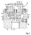
- FIG. 2 in an enlarged view a in FIG. 1 labeled II section of the pump with a closure element according to a first embodiment
- FIG. 3 the closure element according to a second embodiment
- FIG. 4 the detail II with a third embodiment of the pump.
- a pump which is a high-pressure fuel pump for fuel delivery in a fuel injection system of an internal combustion engine.
- the pump has at least one pump element 10, which in turn has a pump piston 12 which is driven by a drive in a lifting movement, is guided in a cylinder bore 14 of a housing part 16 of the high-pressure pump and limits a pump working chamber 18 in the cylinder bore 14.
- a drive shaft 20 may be provided with a cam 22 or eccentric, where the pump piston 12 is supported directly or via a plunger, for example a roller tappet.
- the pump working chamber 18 can be connected to a fuel inlet 26 via an inlet valve 24 and via an outlet valve 28 to a reservoir 30.
- the pump working chamber 18 can be filled with fuel when the inlet valve 24 is open.
- fuel is expelled from the pump working chamber 18 through the open outlet valve 28 and conveyed into the reservoir 30 when the inlet valve 24 is closed.
- FIG. 2 a section of the pump is shown with a portion of the housing part 16, in which the inlet valve 24 is arranged.
- the housing part 16 of the high-pressure pump is connected to the cylinder bore 14 on the pump piston 12 side facing away from a through hole 32 with a larger diameter than the cylinder bore 14, which opens on the outside of the housing part 16.
- the inlet valve 24 has a valve housing 34 which is inserted into the through hole 32 forming a receptacle for the valve housing 34, wherein the valve housing 34 has a larger diameter than the cylinder bore 14 and at an annular shoulder formed at the transition from the cylinder bore 14 to the through hole 32 36 comes to the plant.
- the valve housing 34 can rest directly or via a sealing element 38 on the annular shoulder 36.
- valve housing 34 is held in the housing part 16 by means of a fastening element, which is designed, for example, as a screw 40 screwed into the through-bore 32. Between the outer jacket of the valve housing 34 and the through hole 32, an annular space 42 is formed, in which the inlet 26 opens.
- the valve housing 34 has a central bore 44, which extends at least approximately coaxially to the cylinder bore 14 and the through hole 32 and in which a piston-shaped valve member 46 of the inlet valve 24 is slidably disposed.
- the valve member 46 has a shaft 48, which is guided displaceably in the bore 44, and a larger diameter in diameter relative to the shaft 48 head 50, which projects into the pump working chamber 18.
- the head 50 cooperates with a sealing surface 52 disposed thereon with a valve seat 54 formed on the valve housing 34.
- one or more transverse bores 56 are provided, through which a diameter relative to the shaft 48 leading portion enlarged portion of the bore 44 is connected to the annular space 42.
- valve spring 58 On the pump working chamber 18 side facing away from the valve housing 34, a valve spring 58 is arranged, which is formed as the protruding from the valve housing 34 shank 48 of the valve member 46 surrounding helical compression spring.
- the valve spring 58 is supported on the one hand via a spring plate 60 fastened to the shaft 48 on the valve member 46 and on the other hand on the valve housing 34.
- the screw 40 has a central opening 62 into which protrudes from the valve housing 34 protruding end of the shaft 48 of the valve member 46 with the spring plate 60 and the valve spring 58.
- a closure member 64 is arranged, through which the through hole 32 is sealed to the outside.
- a suction chamber is limited, which comprises the annular space 42, lying within the opening 62 in the screw 40 space 66 and lying between the screw 40 and the closure member 64 space 68.
- the space 66 and / or the space 68 is connected to the annular space 42 via at least one opening 69 in the valve housing 34 and / or in the screw 40.
- the closure member 64 is cup-shaped and has an at least approximately cylindrical shell portion 70 and one of the screw 40 opposite end occluding bottom portion 72.
- the housing portion 16 facing end portion of the jacket portion 70 is fixed to a through hole 32 surrounding collar 74 of the housing part 16, for example, screwed or pressed onto this.
- an elastic sealing element 76 may be arranged between the jacket region 70 and the collar 74.
- At least the bottom region 72 of the closure element 64 is elastically deformable, preferably such that it can bulge inward in the direction of the longitudinal axis 65 of the closure element 64 into the space 68 and outwards, as shown in FIG FIG. 2 is illustrated with dashed lines.
- the Floor area 72 is at least approximately flat in the undeformed state. On the one hand, to allow the elastic deformability of the bottom region 72 and, on the other hand, sufficient rigidity of the jacket region 70 for secure attachment to the housing part 16, it can be provided that the bottom region 72 has a smaller wall thickness than the jacket region 70.
- the closure element 64 can be made of metal or plastic be.
- the closure element 164 is shown according to a second embodiment.
- the closure element 164 is also cup-shaped, but has an attached to the collar 74 of the housing part 16 edge portion 170 and a starting from the edge portion 170 of the screw 40 convexly outwardly curved bottom portion 172 which is elastically deformable.
- the elastic deformability of the bottom region 172 can be achieved or improved, as in the first exemplary embodiment, by means of a wall thickness of the bottom region 172 which is smaller than the edge region 170.
- the edge region 170 can be screwed or pressed onto the collar 74 of the housing part 16.
- the closure member 164 may also be made of metal or plastic.
- FIG. 4 is a section of the pump according to a third embodiment shown, in which, unlike the first and second embodiments, the inlet valve 124 does not have a separate valve housing.
- the through hole 132 adjoining the cylinder bore 14 is provided, which firstly has a bore portion 132a of smaller diameter than the cylinder bore 14 adjacent to the cylinder bore 14 and then a larger diameter bore portion 132b thereon.
- the inlet valve 124 has the piston-shaped valve member 146, whose shaft 148 guided in the bore portion 130 a is and whose head 150 projects into the pump working chamber 18.
- the head 150 cooperates with the sealing surface 152 disposed thereon with the valve seat 154, which is formed in the housing part 16 at the transition from the cylinder bore 14 to the bore portion 132a.
- the shaft 148 of the valve member 146 protrudes on the side facing away from the pump working chamber 18 from the bore portion 132a out into the bore portion 132b and on this, the spring plate 160 is fixed, on which the valve spring 158 is supported, on the other hand on the housing part 116 is supported.
- the bore section 132b is sealed to the outside on its side remote from the bore section 132a by the closure element 64.
- the space 142 which forms the suction space of the inlet valve 124, is delimited in the bore section 132b.
- the inlet 26 opens into the suction chamber 142 and the suction chamber 142 is connected via one or more holes 156 with the bore portion 132 a. With the valve member 146 open, fuel can flow from the suction chamber 142 through the bores 156 and between the sealing surface 152 and the valve seat 154 into the pump working chamber 18.
- the closure element 64 is formed as in the first or second embodiment and thus at least partially elastically deformable to allow changes in volume of the suction chamber 142 and thereby to prevent or at least reduce pressure fluctuations in the suction chamber 142.
- the closure element 64 is connected to a collar 174 of the housing part 116 surrounding the bore section 132b, for example screwed or pressed onto the latter. Between the collar 174 and the closure element 64, a sealing element 76 may be arranged.
Landscapes
- Engineering & Computer Science (AREA)
- Mechanical Engineering (AREA)
- General Engineering & Computer Science (AREA)
- Chemical & Material Sciences (AREA)
- Combustion & Propulsion (AREA)
- Details Of Reciprocating Pumps (AREA)
Applications Claiming Priority (1)
| Application Number | Priority Date | Filing Date | Title |
|---|---|---|---|
| DE102015203345.7A DE102015203345A1 (de) | 2015-02-25 | 2015-02-25 | Pumpe, insbesondere Kraftstoffhochdruckpumpe |
Publications (2)
| Publication Number | Publication Date |
|---|---|
| EP3061967A1 true EP3061967A1 (fr) | 2016-08-31 |
| EP3061967B1 EP3061967B1 (fr) | 2018-08-15 |
Family
ID=55027681
Family Applications (1)
| Application Number | Title | Priority Date | Filing Date |
|---|---|---|---|
| EP16150017.8A Active EP3061967B1 (fr) | 2015-02-25 | 2016-01-04 | Pompe, en particulier pompe haute pression pour carburant |
Country Status (2)
| Country | Link |
|---|---|
| EP (1) | EP3061967B1 (fr) |
| DE (1) | DE102015203345A1 (fr) |
Cited By (2)
| Publication number | Priority date | Publication date | Assignee | Title |
|---|---|---|---|---|
| CN108071538A (zh) * | 2016-11-14 | 2018-05-25 | 罗伯特·博世有限公司 | 用于将燃料、优选地柴油燃料供给至内燃机的泵组件 |
| WO2018158074A1 (fr) * | 2017-03-02 | 2018-09-07 | Robert Bosch Gmbh | Élément de pompe pour pompe à haute pression |
Citations (4)
| Publication number | Priority date | Publication date | Assignee | Title |
|---|---|---|---|---|
| GB2022691A (en) * | 1978-05-31 | 1979-12-19 | Bosch Gmbh Robert | Silencer for fluid feed pumps having pressure oscillations in the pumped flow medium |
| DE19907869A1 (de) * | 1998-03-02 | 1999-09-09 | Zexel Corp | Plungerkolbenpumpe |
| DE10327408A1 (de) * | 2002-10-19 | 2004-04-29 | Robert Bosch Gmbh | Vorrichtung zum Dämpfen von Druckpulsationen in einem Fluidsystem, insbesondere in einem Kraftstoffsystem einer Brennkraftmaschine |
| DE102004013244A1 (de) | 2004-03-18 | 2005-10-06 | Robert Bosch Gmbh | Hochdruckpumpe, insbesondere für eine Kraftstoffeinspritzeinrichtung einer Brennkraftmaschine |
-
2015
- 2015-02-25 DE DE102015203345.7A patent/DE102015203345A1/de not_active Withdrawn
-
2016
- 2016-01-04 EP EP16150017.8A patent/EP3061967B1/fr active Active
Patent Citations (4)
| Publication number | Priority date | Publication date | Assignee | Title |
|---|---|---|---|---|
| GB2022691A (en) * | 1978-05-31 | 1979-12-19 | Bosch Gmbh Robert | Silencer for fluid feed pumps having pressure oscillations in the pumped flow medium |
| DE19907869A1 (de) * | 1998-03-02 | 1999-09-09 | Zexel Corp | Plungerkolbenpumpe |
| DE10327408A1 (de) * | 2002-10-19 | 2004-04-29 | Robert Bosch Gmbh | Vorrichtung zum Dämpfen von Druckpulsationen in einem Fluidsystem, insbesondere in einem Kraftstoffsystem einer Brennkraftmaschine |
| DE102004013244A1 (de) | 2004-03-18 | 2005-10-06 | Robert Bosch Gmbh | Hochdruckpumpe, insbesondere für eine Kraftstoffeinspritzeinrichtung einer Brennkraftmaschine |
Cited By (3)
| Publication number | Priority date | Publication date | Assignee | Title |
|---|---|---|---|---|
| CN108071538A (zh) * | 2016-11-14 | 2018-05-25 | 罗伯特·博世有限公司 | 用于将燃料、优选地柴油燃料供给至内燃机的泵组件 |
| CN108071538B (zh) * | 2016-11-14 | 2022-03-22 | 罗伯特·博世有限公司 | 用于将燃料、优选地柴油燃料供给至内燃机的泵组件 |
| WO2018158074A1 (fr) * | 2017-03-02 | 2018-09-07 | Robert Bosch Gmbh | Élément de pompe pour pompe à haute pression |
Also Published As
| Publication number | Publication date |
|---|---|
| EP3061967B1 (fr) | 2018-08-15 |
| DE102015203345A1 (de) | 2016-08-25 |
Similar Documents
| Publication | Publication Date | Title |
|---|---|---|
| EP1727983B1 (fr) | Pompe haute pression, notamment destinee a un dispositif d'injection de carburant d'un moteur a combustion interne | |
| EP2798191B1 (fr) | Soupape de décharge de carburant pour un injecteur de carburant et injecteur de carburant équipé d'une soupape de décharge de carburant | |
| DE19541507A1 (de) | Kraftstoffeinspritzeinrichtung für Brennkraftmaschinen | |
| EP1636488B1 (fr) | Soupape de non-retour conçue en particulier pour une pompe haute pression d'un dispositif d'injection de carburant pour un moteur a combustion interne | |
| WO2005124153A1 (fr) | Pompe haute pression conçue pour un dispositif d'injection de carburant d'un moteur a combustion interne | |
| DE102009045113A1 (de) | Druckbegrenzungseinrichtung | |
| DE102011089857A1 (de) | Pumpe, insbesondere Kraftstoffhochdruckpumpe für eine Kraftstoffeinspritzeinrichtung | |
| EP3061967B1 (fr) | Pompe, en particulier pompe haute pression pour carburant | |
| EP1599668B1 (fr) | Dispositif d'injection de carburant pour un moteur a combustion interne | |
| EP2795094B1 (fr) | Pompe, en particulier pompe haute pression carburant pour un dispositif d'injection de carburant | |
| DE102013210019A1 (de) | Hochdruckpumpe für ein Kraftstoffeinspritzsystem mit einem Saugventil | |
| EP1736662A1 (fr) | Clapet anti-retour, notamment pour une pompe à haute pression de un dispositif d'injection de combustible pour un moteur à combustion interne | |
| EP1537334B1 (fr) | Pompe, notamment pour un systeme d'injection de carburant destine a un moteur a combustion interne | |
| EP1413756B1 (fr) | Pompe à combustible | |
| EP1759115B1 (fr) | Pompe a haute pression pour un dispositif d'injection de carburant d'un moteur a combustion interne | |
| DE102008001824A1 (de) | Pumpe, insbesondere Kraftstoffhochdruckpumpe, und Rückschlagventil, insbesondere für eine Pumpe | |
| DE102016106232B3 (de) | Radialkolbenpumpe, insbesondere für Kraftstoff, mit mehreren Speicherbohrungen im Gehäuse der Radialkolbenpumpe | |
| DE102013212479A1 (de) | Einlassventil für eine Pumpe und Pumpe mit Einlassventil | |
| EP1284360B1 (fr) | Dispositif d'injection de carburant pour moteur à combustion interne | |
| WO2016142072A1 (fr) | Pompe à haute pression de carburant, notamment pour un dispositif d'injection de carburant d'un moteur à combustion interne | |
| DE102012201308A1 (de) | Hochdruckpumpe | |
| DE102021209837A1 (de) | Zyklisch arbeitende Pumpe, insbesondere Kraftstoff-Hochdruckkolbenpumpe | |
| DE102013217357A1 (de) | Pumpe, insbesondere eine Kraftstoffhochdruckpumpe | |
| DE102013204897A1 (de) | Pumpe, insbesondere Kraftstoffhochdruckpumpe für eine Kraftstoffeinspritzeinrichtung | |
| WO2015052083A1 (fr) | Pompe, en particulier pompe haute pression à carburant |
Legal Events
| Date | Code | Title | Description |
|---|---|---|---|
| PUAI | Public reference made under article 153(3) epc to a published international application that has entered the european phase |
Free format text: ORIGINAL CODE: 0009012 |
|
| AK | Designated contracting states |
Kind code of ref document: A1 Designated state(s): AL AT BE BG CH CY CZ DE DK EE ES FI FR GB GR HR HU IE IS IT LI LT LU LV MC MK MT NL NO PL PT RO RS SE SI SK SM TR |
|
| AX | Request for extension of the european patent |
Extension state: BA ME |
|
| STAA | Information on the status of an ep patent application or granted ep patent |
Free format text: STATUS: REQUEST FOR EXAMINATION WAS MADE |
|
| 17P | Request for examination filed |
Effective date: 20170228 |
|
| RBV | Designated contracting states (corrected) |
Designated state(s): AL AT BE BG CH CY CZ DE DK EE ES FI FR GB GR HR HU IE IS IT LI LT LU LV MC MK MT NL NO PL PT RO RS SE SI SK SM TR |
|
| RIC1 | Information provided on ipc code assigned before grant |
Ipc: F04B 11/00 20060101AFI20180228BHEP Ipc: F02M 59/44 20060101ALI20180228BHEP Ipc: F02M 59/02 20060101ALI20180228BHEP |
|
| GRAP | Despatch of communication of intention to grant a patent |
Free format text: ORIGINAL CODE: EPIDOSNIGR1 |
|
| STAA | Information on the status of an ep patent application or granted ep patent |
Free format text: STATUS: GRANT OF PATENT IS INTENDED |
|
| INTG | Intention to grant announced |
Effective date: 20180418 |
|
| GRAS | Grant fee paid |
Free format text: ORIGINAL CODE: EPIDOSNIGR3 |
|
| GRAA | (expected) grant |
Free format text: ORIGINAL CODE: 0009210 |
|
| STAA | Information on the status of an ep patent application or granted ep patent |
Free format text: STATUS: THE PATENT HAS BEEN GRANTED |
|
| AK | Designated contracting states |
Kind code of ref document: B1 Designated state(s): AL AT BE BG CH CY CZ DE DK EE ES FI FR GB GR HR HU IE IS IT LI LT LU LV MC MK MT NL NO PL PT RO RS SE SI SK SM TR |
|
| REG | Reference to a national code |
Ref country code: CH Ref legal event code: EP Ref country code: GB Ref legal event code: FG4D Free format text: NOT ENGLISH Ref country code: AT Ref legal event code: REF Ref document number: 1030092 Country of ref document: AT Kind code of ref document: T Effective date: 20180815 |
|
| REG | Reference to a national code |
Ref country code: IE Ref legal event code: FG4D Free format text: LANGUAGE OF EP DOCUMENT: GERMAN |
|
| REG | Reference to a national code |
Ref country code: DE Ref legal event code: R096 Ref document number: 502016001636 Country of ref document: DE |
|
| REG | Reference to a national code |
Ref country code: NL Ref legal event code: MP Effective date: 20180815 |
|
| REG | Reference to a national code |
Ref country code: LT Ref legal event code: MG4D |
|
| PG25 | Lapsed in a contracting state [announced via postgrant information from national office to epo] |
Ref country code: BG Free format text: LAPSE BECAUSE OF FAILURE TO SUBMIT A TRANSLATION OF THE DESCRIPTION OR TO PAY THE FEE WITHIN THE PRESCRIBED TIME-LIMIT Effective date: 20181115 Ref country code: SE Free format text: LAPSE BECAUSE OF FAILURE TO SUBMIT A TRANSLATION OF THE DESCRIPTION OR TO PAY THE FEE WITHIN THE PRESCRIBED TIME-LIMIT Effective date: 20180815 Ref country code: GR Free format text: LAPSE BECAUSE OF FAILURE TO SUBMIT A TRANSLATION OF THE DESCRIPTION OR TO PAY THE FEE WITHIN THE PRESCRIBED TIME-LIMIT Effective date: 20181116 Ref country code: NL Free format text: LAPSE BECAUSE OF FAILURE TO SUBMIT A TRANSLATION OF THE DESCRIPTION OR TO PAY THE FEE WITHIN THE PRESCRIBED TIME-LIMIT Effective date: 20180815 Ref country code: LT Free format text: LAPSE BECAUSE OF FAILURE TO SUBMIT A TRANSLATION OF THE DESCRIPTION OR TO PAY THE FEE WITHIN THE PRESCRIBED TIME-LIMIT Effective date: 20180815 Ref country code: FI Free format text: LAPSE BECAUSE OF FAILURE TO SUBMIT A TRANSLATION OF THE DESCRIPTION OR TO PAY THE FEE WITHIN THE PRESCRIBED TIME-LIMIT Effective date: 20180815 Ref country code: RS Free format text: LAPSE BECAUSE OF FAILURE TO SUBMIT A TRANSLATION OF THE DESCRIPTION OR TO PAY THE FEE WITHIN THE PRESCRIBED TIME-LIMIT Effective date: 20180815 Ref country code: NO Free format text: LAPSE BECAUSE OF FAILURE TO SUBMIT A TRANSLATION OF THE DESCRIPTION OR TO PAY THE FEE WITHIN THE PRESCRIBED TIME-LIMIT Effective date: 20181115 Ref country code: IS Free format text: LAPSE BECAUSE OF FAILURE TO SUBMIT A TRANSLATION OF THE DESCRIPTION OR TO PAY THE FEE WITHIN THE PRESCRIBED TIME-LIMIT Effective date: 20181215 |
|
| PG25 | Lapsed in a contracting state [announced via postgrant information from national office to epo] |
Ref country code: LV Free format text: LAPSE BECAUSE OF FAILURE TO SUBMIT A TRANSLATION OF THE DESCRIPTION OR TO PAY THE FEE WITHIN THE PRESCRIBED TIME-LIMIT Effective date: 20180815 Ref country code: HR Free format text: LAPSE BECAUSE OF FAILURE TO SUBMIT A TRANSLATION OF THE DESCRIPTION OR TO PAY THE FEE WITHIN THE PRESCRIBED TIME-LIMIT Effective date: 20180815 Ref country code: AL Free format text: LAPSE BECAUSE OF FAILURE TO SUBMIT A TRANSLATION OF THE DESCRIPTION OR TO PAY THE FEE WITHIN THE PRESCRIBED TIME-LIMIT Effective date: 20180815 |
|
| PG25 | Lapsed in a contracting state [announced via postgrant information from national office to epo] |
Ref country code: RO Free format text: LAPSE BECAUSE OF FAILURE TO SUBMIT A TRANSLATION OF THE DESCRIPTION OR TO PAY THE FEE WITHIN THE PRESCRIBED TIME-LIMIT Effective date: 20180815 Ref country code: CZ Free format text: LAPSE BECAUSE OF FAILURE TO SUBMIT A TRANSLATION OF THE DESCRIPTION OR TO PAY THE FEE WITHIN THE PRESCRIBED TIME-LIMIT Effective date: 20180815 Ref country code: IT Free format text: LAPSE BECAUSE OF FAILURE TO SUBMIT A TRANSLATION OF THE DESCRIPTION OR TO PAY THE FEE WITHIN THE PRESCRIBED TIME-LIMIT Effective date: 20180815 Ref country code: EE Free format text: LAPSE BECAUSE OF FAILURE TO SUBMIT A TRANSLATION OF THE DESCRIPTION OR TO PAY THE FEE WITHIN THE PRESCRIBED TIME-LIMIT Effective date: 20180815 Ref country code: ES Free format text: LAPSE BECAUSE OF FAILURE TO SUBMIT A TRANSLATION OF THE DESCRIPTION OR TO PAY THE FEE WITHIN THE PRESCRIBED TIME-LIMIT Effective date: 20180815 Ref country code: PL Free format text: LAPSE BECAUSE OF FAILURE TO SUBMIT A TRANSLATION OF THE DESCRIPTION OR TO PAY THE FEE WITHIN THE PRESCRIBED TIME-LIMIT Effective date: 20180815 |
|
| REG | Reference to a national code |
Ref country code: DE Ref legal event code: R097 Ref document number: 502016001636 Country of ref document: DE |
|
| PG25 | Lapsed in a contracting state [announced via postgrant information from national office to epo] |
Ref country code: SK Free format text: LAPSE BECAUSE OF FAILURE TO SUBMIT A TRANSLATION OF THE DESCRIPTION OR TO PAY THE FEE WITHIN THE PRESCRIBED TIME-LIMIT Effective date: 20180815 Ref country code: DK Free format text: LAPSE BECAUSE OF FAILURE TO SUBMIT A TRANSLATION OF THE DESCRIPTION OR TO PAY THE FEE WITHIN THE PRESCRIBED TIME-LIMIT Effective date: 20180815 Ref country code: SM Free format text: LAPSE BECAUSE OF FAILURE TO SUBMIT A TRANSLATION OF THE DESCRIPTION OR TO PAY THE FEE WITHIN THE PRESCRIBED TIME-LIMIT Effective date: 20180815 |
|
| PLBE | No opposition filed within time limit |
Free format text: ORIGINAL CODE: 0009261 |
|
| STAA | Information on the status of an ep patent application or granted ep patent |
Free format text: STATUS: NO OPPOSITION FILED WITHIN TIME LIMIT |
|
| 26N | No opposition filed |
Effective date: 20190516 |
|
| PG25 | Lapsed in a contracting state [announced via postgrant information from national office to epo] |
Ref country code: SI Free format text: LAPSE BECAUSE OF FAILURE TO SUBMIT A TRANSLATION OF THE DESCRIPTION OR TO PAY THE FEE WITHIN THE PRESCRIBED TIME-LIMIT Effective date: 20180815 Ref country code: MC Free format text: LAPSE BECAUSE OF FAILURE TO SUBMIT A TRANSLATION OF THE DESCRIPTION OR TO PAY THE FEE WITHIN THE PRESCRIBED TIME-LIMIT Effective date: 20180815 |
|
| REG | Reference to a national code |
Ref country code: CH Ref legal event code: PL |
|
| PG25 | Lapsed in a contracting state [announced via postgrant information from national office to epo] |
Ref country code: LU Free format text: LAPSE BECAUSE OF NON-PAYMENT OF DUE FEES Effective date: 20190104 |
|
| REG | Reference to a national code |
Ref country code: BE Ref legal event code: MM Effective date: 20190131 |
|
| REG | Reference to a national code |
Ref country code: IE Ref legal event code: MM4A |
|
| PG25 | Lapsed in a contracting state [announced via postgrant information from national office to epo] |
Ref country code: BE Free format text: LAPSE BECAUSE OF NON-PAYMENT OF DUE FEES Effective date: 20190131 |
|
| PG25 | Lapsed in a contracting state [announced via postgrant information from national office to epo] |
Ref country code: CH Free format text: LAPSE BECAUSE OF NON-PAYMENT OF DUE FEES Effective date: 20190131 Ref country code: LI Free format text: LAPSE BECAUSE OF NON-PAYMENT OF DUE FEES Effective date: 20190131 |
|
| PG25 | Lapsed in a contracting state [announced via postgrant information from national office to epo] |
Ref country code: IE Free format text: LAPSE BECAUSE OF NON-PAYMENT OF DUE FEES Effective date: 20190104 |
|
| PG25 | Lapsed in a contracting state [announced via postgrant information from national office to epo] |
Ref country code: TR Free format text: LAPSE BECAUSE OF FAILURE TO SUBMIT A TRANSLATION OF THE DESCRIPTION OR TO PAY THE FEE WITHIN THE PRESCRIBED TIME-LIMIT Effective date: 20180815 |
|
| PG25 | Lapsed in a contracting state [announced via postgrant information from national office to epo] |
Ref country code: PT Free format text: LAPSE BECAUSE OF FAILURE TO SUBMIT A TRANSLATION OF THE DESCRIPTION OR TO PAY THE FEE WITHIN THE PRESCRIBED TIME-LIMIT Effective date: 20181215 Ref country code: MT Free format text: LAPSE BECAUSE OF FAILURE TO SUBMIT A TRANSLATION OF THE DESCRIPTION OR TO PAY THE FEE WITHIN THE PRESCRIBED TIME-LIMIT Effective date: 20180815 |
|
| GBPC | Gb: european patent ceased through non-payment of renewal fee |
Effective date: 20200104 |
|
| PG25 | Lapsed in a contracting state [announced via postgrant information from national office to epo] |
Ref country code: GB Free format text: LAPSE BECAUSE OF NON-PAYMENT OF DUE FEES Effective date: 20200104 |
|
| PG25 | Lapsed in a contracting state [announced via postgrant information from national office to epo] |
Ref country code: CY Free format text: LAPSE BECAUSE OF FAILURE TO SUBMIT A TRANSLATION OF THE DESCRIPTION OR TO PAY THE FEE WITHIN THE PRESCRIBED TIME-LIMIT Effective date: 20180815 |
|
| PG25 | Lapsed in a contracting state [announced via postgrant information from national office to epo] |
Ref country code: HU Free format text: LAPSE BECAUSE OF FAILURE TO SUBMIT A TRANSLATION OF THE DESCRIPTION OR TO PAY THE FEE WITHIN THE PRESCRIBED TIME-LIMIT; INVALID AB INITIO Effective date: 20160104 |
|
| REG | Reference to a national code |
Ref country code: AT Ref legal event code: MM01 Ref document number: 1030092 Country of ref document: AT Kind code of ref document: T Effective date: 20210104 |
|
| PG25 | Lapsed in a contracting state [announced via postgrant information from national office to epo] |
Ref country code: AT Free format text: LAPSE BECAUSE OF NON-PAYMENT OF DUE FEES Effective date: 20210104 |
|
| PG25 | Lapsed in a contracting state [announced via postgrant information from national office to epo] |
Ref country code: MK Free format text: LAPSE BECAUSE OF FAILURE TO SUBMIT A TRANSLATION OF THE DESCRIPTION OR TO PAY THE FEE WITHIN THE PRESCRIBED TIME-LIMIT Effective date: 20180815 |
|
| PGFP | Annual fee paid to national office [announced via postgrant information from national office to epo] |
Ref country code: FR Payment date: 20230123 Year of fee payment: 8 |
|
| PGFP | Annual fee paid to national office [announced via postgrant information from national office to epo] |
Ref country code: DE Payment date: 20240322 Year of fee payment: 9 |