EP3061967A1 - Pumpe, insbesondere kraftstoffhochdruckpumpe - Google Patents
Pumpe, insbesondere kraftstoffhochdruckpumpe Download PDFInfo
- Publication number
- EP3061967A1 EP3061967A1 EP16150017.8A EP16150017A EP3061967A1 EP 3061967 A1 EP3061967 A1 EP 3061967A1 EP 16150017 A EP16150017 A EP 16150017A EP 3061967 A1 EP3061967 A1 EP 3061967A1
- Authority
- EP
- European Patent Office
- Prior art keywords
- pump
- closure element
- housing part
- valve
- region
- Prior art date
- Legal status (The legal status is an assumption and is not a legal conclusion. Google has not performed a legal analysis and makes no representation as to the accuracy of the status listed.)
- Granted
Links
Images


Classifications
-
- F—MECHANICAL ENGINEERING; LIGHTING; HEATING; WEAPONS; BLASTING
- F04—POSITIVE - DISPLACEMENT MACHINES FOR LIQUIDS; PUMPS FOR LIQUIDS OR ELASTIC FLUIDS
- F04B—POSITIVE-DISPLACEMENT MACHINES FOR LIQUIDS; PUMPS
- F04B11/00—Equalisation of pulses, e.g. by use of air vessels; Counteracting cavitation
- F04B11/0008—Equalisation of pulses, e.g. by use of air vessels; Counteracting cavitation using accumulators
- F04B11/0033—Equalisation of pulses, e.g. by use of air vessels; Counteracting cavitation using accumulators with a mechanical spring
-
- F—MECHANICAL ENGINEERING; LIGHTING; HEATING; WEAPONS; BLASTING
- F02—COMBUSTION ENGINES; HOT-GAS OR COMBUSTION-PRODUCT ENGINE PLANTS
- F02M—SUPPLYING COMBUSTION ENGINES IN GENERAL WITH COMBUSTIBLE MIXTURES OR CONSTITUENTS THEREOF
- F02M59/00—Pumps specially adapted for fuel-injection and not provided for in groups F02M39/00 -F02M57/00, e.g. rotary cylinder-block type of pumps
- F02M59/02—Pumps specially adapted for fuel-injection and not provided for in groups F02M39/00 -F02M57/00, e.g. rotary cylinder-block type of pumps of reciprocating-piston or reciprocating-cylinder type
-
- F—MECHANICAL ENGINEERING; LIGHTING; HEATING; WEAPONS; BLASTING
- F02—COMBUSTION ENGINES; HOT-GAS OR COMBUSTION-PRODUCT ENGINE PLANTS
- F02M—SUPPLYING COMBUSTION ENGINES IN GENERAL WITH COMBUSTIBLE MIXTURES OR CONSTITUENTS THEREOF
- F02M59/00—Pumps specially adapted for fuel-injection and not provided for in groups F02M39/00 -F02M57/00, e.g. rotary cylinder-block type of pumps
- F02M59/44—Details, components parts, or accessories not provided for in, or of interest apart from, the apparatus of groups F02M59/02 - F02M59/42; Pumps having transducers, e.g. to measure displacement of pump rack or piston
-
- F—MECHANICAL ENGINEERING; LIGHTING; HEATING; WEAPONS; BLASTING
- F02—COMBUSTION ENGINES; HOT-GAS OR COMBUSTION-PRODUCT ENGINE PLANTS
- F02M—SUPPLYING COMBUSTION ENGINES IN GENERAL WITH COMBUSTIBLE MIXTURES OR CONSTITUENTS THEREOF
- F02M2200/00—Details of fuel-injection apparatus, not otherwise provided for
- F02M2200/03—Fuel-injection apparatus having means for reducing or avoiding stress, e.g. the stress caused by mechanical force, by fluid pressure or by temperature variations
-
- F—MECHANICAL ENGINEERING; LIGHTING; HEATING; WEAPONS; BLASTING
- F02—COMBUSTION ENGINES; HOT-GAS OR COMBUSTION-PRODUCT ENGINE PLANTS
- F02M—SUPPLYING COMBUSTION ENGINES IN GENERAL WITH COMBUSTIBLE MIXTURES OR CONSTITUENTS THEREOF
- F02M2200/00—Details of fuel-injection apparatus, not otherwise provided for
- F02M2200/26—Fuel-injection apparatus with elastically deformable elements other than coil springs
-
- F—MECHANICAL ENGINEERING; LIGHTING; HEATING; WEAPONS; BLASTING
- F02—COMBUSTION ENGINES; HOT-GAS OR COMBUSTION-PRODUCT ENGINE PLANTS
- F02M—SUPPLYING COMBUSTION ENGINES IN GENERAL WITH COMBUSTIBLE MIXTURES OR CONSTITUENTS THEREOF
- F02M2200/00—Details of fuel-injection apparatus, not otherwise provided for
- F02M2200/90—Selection of particular materials
- F02M2200/9015—Elastomeric or plastic materials
-
- F—MECHANICAL ENGINEERING; LIGHTING; HEATING; WEAPONS; BLASTING
- F02—COMBUSTION ENGINES; HOT-GAS OR COMBUSTION-PRODUCT ENGINE PLANTS
- F02M—SUPPLYING COMBUSTION ENGINES IN GENERAL WITH COMBUSTIBLE MIXTURES OR CONSTITUENTS THEREOF
- F02M59/00—Pumps specially adapted for fuel-injection and not provided for in groups F02M39/00 -F02M57/00, e.g. rotary cylinder-block type of pumps
- F02M59/44—Details, components parts, or accessories not provided for in, or of interest apart from, the apparatus of groups F02M59/02 - F02M59/42; Pumps having transducers, e.g. to measure displacement of pump rack or piston
- F02M59/48—Assembling; Disassembling; Replacing
- F02M59/485—Means for fixing delivery valve casing and barrel to each other or to pump casing
Definitions
- the invention relates to a pump, in particular high-pressure fuel pump, according to the preamble of claim 1.
- Such a pump in the form of a high-pressure fuel pump is through DE 10 2004 013 244 A1 known.
- This pump has at least one pump element with a driven in a stroke pump piston, which limits a pump chamber in a housing part of the pump.
- the pump working chamber can be connected via the inlet valve with an inlet for the pumped medium.
- the inlet opens into a suction chamber defined by the housing part of the pump and a closure element connected thereto.
- the volume of the suction chamber is changed by the opening and closing of the inlet valve, whereby pressure pulsations are generated.
- This pressure pulsations lead to high loads on the components of the pump and also to functional impairments such as poor filling of the pump working space, noise and high stress of seals in the pump.
- the pump according to the invention with the features of claim 1 has the advantage that pressure pulsations in the suction chamber avoided or at least reduced. This is achieved by the elastic deformability of the closure element, wherein the volume of the suction chamber at pressure increase enlarged and reduced when pressure decreases. In the case of elastic deformation of the closure element, hardly any energy is lost, so that volumes stored on pressure increase are released again during springback of the closure element.
- FIG. 1 a schematic longitudinal section through a high-pressure pump
- FIG. 2 in an enlarged view a in FIG. 1 labeled II section of the pump with a closure element according to a first embodiment
- FIG. 3 the closure element according to a second embodiment
- FIG. 4 the detail II with a third embodiment of the pump.
- a pump which is a high-pressure fuel pump for fuel delivery in a fuel injection system of an internal combustion engine.
- the pump has at least one pump element 10, which in turn has a pump piston 12 which is driven by a drive in a lifting movement, is guided in a cylinder bore 14 of a housing part 16 of the high-pressure pump and limits a pump working chamber 18 in the cylinder bore 14.
- a drive shaft 20 may be provided with a cam 22 or eccentric, where the pump piston 12 is supported directly or via a plunger, for example a roller tappet.
- the pump working chamber 18 can be connected to a fuel inlet 26 via an inlet valve 24 and via an outlet valve 28 to a reservoir 30.
- the pump working chamber 18 can be filled with fuel when the inlet valve 24 is open.
- fuel is expelled from the pump working chamber 18 through the open outlet valve 28 and conveyed into the reservoir 30 when the inlet valve 24 is closed.
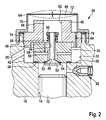
- FIG. 2 a section of the pump is shown with a portion of the housing part 16, in which the inlet valve 24 is arranged.
- the housing part 16 of the high-pressure pump is connected to the cylinder bore 14 on the pump piston 12 side facing away from a through hole 32 with a larger diameter than the cylinder bore 14, which opens on the outside of the housing part 16.
- the inlet valve 24 has a valve housing 34 which is inserted into the through hole 32 forming a receptacle for the valve housing 34, wherein the valve housing 34 has a larger diameter than the cylinder bore 14 and at an annular shoulder formed at the transition from the cylinder bore 14 to the through hole 32 36 comes to the plant.
- the valve housing 34 can rest directly or via a sealing element 38 on the annular shoulder 36.
- valve housing 34 is held in the housing part 16 by means of a fastening element, which is designed, for example, as a screw 40 screwed into the through-bore 32. Between the outer jacket of the valve housing 34 and the through hole 32, an annular space 42 is formed, in which the inlet 26 opens.
- the valve housing 34 has a central bore 44, which extends at least approximately coaxially to the cylinder bore 14 and the through hole 32 and in which a piston-shaped valve member 46 of the inlet valve 24 is slidably disposed.
- the valve member 46 has a shaft 48, which is guided displaceably in the bore 44, and a larger diameter in diameter relative to the shaft 48 head 50, which projects into the pump working chamber 18.
- the head 50 cooperates with a sealing surface 52 disposed thereon with a valve seat 54 formed on the valve housing 34.
- one or more transverse bores 56 are provided, through which a diameter relative to the shaft 48 leading portion enlarged portion of the bore 44 is connected to the annular space 42.
- valve spring 58 On the pump working chamber 18 side facing away from the valve housing 34, a valve spring 58 is arranged, which is formed as the protruding from the valve housing 34 shank 48 of the valve member 46 surrounding helical compression spring.
- the valve spring 58 is supported on the one hand via a spring plate 60 fastened to the shaft 48 on the valve member 46 and on the other hand on the valve housing 34.
- the screw 40 has a central opening 62 into which protrudes from the valve housing 34 protruding end of the shaft 48 of the valve member 46 with the spring plate 60 and the valve spring 58.
- a closure member 64 is arranged, through which the through hole 32 is sealed to the outside.
- a suction chamber is limited, which comprises the annular space 42, lying within the opening 62 in the screw 40 space 66 and lying between the screw 40 and the closure member 64 space 68.
- the space 66 and / or the space 68 is connected to the annular space 42 via at least one opening 69 in the valve housing 34 and / or in the screw 40.
- the closure member 64 is cup-shaped and has an at least approximately cylindrical shell portion 70 and one of the screw 40 opposite end occluding bottom portion 72.
- the housing portion 16 facing end portion of the jacket portion 70 is fixed to a through hole 32 surrounding collar 74 of the housing part 16, for example, screwed or pressed onto this.
- an elastic sealing element 76 may be arranged between the jacket region 70 and the collar 74.
- At least the bottom region 72 of the closure element 64 is elastically deformable, preferably such that it can bulge inward in the direction of the longitudinal axis 65 of the closure element 64 into the space 68 and outwards, as shown in FIG FIG. 2 is illustrated with dashed lines.
- the Floor area 72 is at least approximately flat in the undeformed state. On the one hand, to allow the elastic deformability of the bottom region 72 and, on the other hand, sufficient rigidity of the jacket region 70 for secure attachment to the housing part 16, it can be provided that the bottom region 72 has a smaller wall thickness than the jacket region 70.
- the closure element 64 can be made of metal or plastic be.
- the closure element 164 is shown according to a second embodiment.
- the closure element 164 is also cup-shaped, but has an attached to the collar 74 of the housing part 16 edge portion 170 and a starting from the edge portion 170 of the screw 40 convexly outwardly curved bottom portion 172 which is elastically deformable.
- the elastic deformability of the bottom region 172 can be achieved or improved, as in the first exemplary embodiment, by means of a wall thickness of the bottom region 172 which is smaller than the edge region 170.
- the edge region 170 can be screwed or pressed onto the collar 74 of the housing part 16.
- the closure member 164 may also be made of metal or plastic.
- FIG. 4 is a section of the pump according to a third embodiment shown, in which, unlike the first and second embodiments, the inlet valve 124 does not have a separate valve housing.
- the through hole 132 adjoining the cylinder bore 14 is provided, which firstly has a bore portion 132a of smaller diameter than the cylinder bore 14 adjacent to the cylinder bore 14 and then a larger diameter bore portion 132b thereon.
- the inlet valve 124 has the piston-shaped valve member 146, whose shaft 148 guided in the bore portion 130 a is and whose head 150 projects into the pump working chamber 18.
- the head 150 cooperates with the sealing surface 152 disposed thereon with the valve seat 154, which is formed in the housing part 16 at the transition from the cylinder bore 14 to the bore portion 132a.
- the shaft 148 of the valve member 146 protrudes on the side facing away from the pump working chamber 18 from the bore portion 132a out into the bore portion 132b and on this, the spring plate 160 is fixed, on which the valve spring 158 is supported, on the other hand on the housing part 116 is supported.
- the bore section 132b is sealed to the outside on its side remote from the bore section 132a by the closure element 64.
- the space 142 which forms the suction space of the inlet valve 124, is delimited in the bore section 132b.
- the inlet 26 opens into the suction chamber 142 and the suction chamber 142 is connected via one or more holes 156 with the bore portion 132 a. With the valve member 146 open, fuel can flow from the suction chamber 142 through the bores 156 and between the sealing surface 152 and the valve seat 154 into the pump working chamber 18.
- the closure element 64 is formed as in the first or second embodiment and thus at least partially elastically deformable to allow changes in volume of the suction chamber 142 and thereby to prevent or at least reduce pressure fluctuations in the suction chamber 142.
- the closure element 64 is connected to a collar 174 of the housing part 116 surrounding the bore section 132b, for example screwed or pressed onto the latter. Between the collar 174 and the closure element 64, a sealing element 76 may be arranged.
Landscapes
- Engineering & Computer Science (AREA)
- Mechanical Engineering (AREA)
- General Engineering & Computer Science (AREA)
- Chemical & Material Sciences (AREA)
- Combustion & Propulsion (AREA)
- Details Of Reciprocating Pumps (AREA)
Abstract
Description
- Die Erfindung betrifft eine Pumpe, insbesondere Kraftstoffhochdruckpumpe, gemäß dem Oberbegriff des Anspruchs 1.
- Eine solche Pumpe in Form einer Kraftstoffhochdruckpumpe ist durch die
DE 10 2004 013 244 A1 bekannt. Diese Pumpe weist wenigstens ein Pumpenelement auf mit einem in einer Hubbewegung angetriebenen Pumpenkolben, der in einem Gehäuseteil der Pumpe einen Pumpenarbeitsraum begrenzt. Der Pumpenarbeitsraum ist über das Einlassventil mit einem Zulauf für das Fördermedium verbindbar. Der Zulauf mündet in einem durch das Gehäuseteil der Pumpe und ein mit diesem verbundenes Verschlusselement begrenzten Saugraum. Im Betrieb der Pumpe wird das Volumen des Saugraums durch das Öffnen und Schließen des Einlassventils verändert, wodurch Druckpulsationen erzeugt werden. Diese Druckpulsationen führen zu hohen Belastungen der Bauteile der Pumpe und auch zu Funktionsbeeinträchtigungen wie beispielsweise schlechter Befüllung des Pumpenarbeitsraums, Geräuschentwicklung und hoher Beanspruchung von Dichtungen in der Pumpe. - Die erfindungsgemäße Pumpe mit den Merkmalen des Anspruchs 1 hat demgegenüber den Vorteil, dass Druckpulsationen im Saugraum vermieden oder zumindest verringert sind. Dies wird durch die elastische Verformbarkeit des Verschlusselements erreicht, wobei sich das Volumen des Saugraums bei Druckerhöhung vergrößert und bei Druckabnahme verringert. Bei elastischer Verformung des Verschlusselements geht kaum Energie verloren so dass bei Druckerhöhung gespeicherte Volumina beim Rückfedern des Verschlusselements wieder abgegeben werden.
- In den abhängigen Ansprüchen sind vorteilhafte Ausgestaltungen und Weiterbildungen der erfindungsgemäßen Pumpe angegeben. In den Ansprüchen 2 bis 5 sind konstruktiv einfache Ausbildungen des Verschlusselements angegeben um dessen elastische Verformbarkeit zu erreichen. Durch die Ausbildung gemäß Anspruch 6 wird die elastische Verformbarkeit weiter verbessert und auf den Bodenbereich des Verschlusselements konzentriert. In den Ansprüchen 7 bis 9 ist eine Anwendung des Verschlusselements bei einem Einlassventil mit separatem Ventilgehäuse angegeben. Im Anspruch 10 ist eine Anwendung des Verschlusselements bei einem in das Gehäuseteil der Pumpe integrierten Einlassventil angegeben.
- Mehrere Ausführungsbeispiele der Erfindung werden nachfolgend anhand der beigefügten Zeichnung näher beschrieben. Es zeigen
Figur 1 einen schematischen Längsschnitt durch eine Hochdruckpumpe,Figur 2 in vergrößerter Darstellung einen inFigur 1 mit II bezeichneten Ausschnitt der Pumpe mit einem Verschlusselement gemäß einem ersten Ausführungsbeispiel,Figur 3 das Verschlusselement gemäß einem zweiten Ausführungsbeispiel undFigur 4 den Ausschnitt II mit einem dritten Ausführungsbeispiel der Pumpe. - In den
Figuren 1 bis 4 ist ausschnittsweise eine Pumpe dargestellt, die eine Kraftstoffhochdruckpumpe zur Kraftstoffförderung in einem Kraftstoffeinspritzsystem einer Brennkraftmaschine ist. Die Pumpe weist wenigstens ein Pumpenelement 10 auf, das wiederum einen Pumpenkolben 12 aufweist, der durch einen Antrieb in einer Hubbewegung angetrieben wird, in einer Zylinderbohrung 14 eines Gehäuseteils 16 der Hochdruckpumpe geführt ist und in der Zylinderbohrung 14 einen Pumpenarbeitsraum 18 begrenzt. Als Antrieb für den Pumpenkolben 12 kann eine Antriebswelle 20 mit einem Nocken 22 oder Exzenter vorgesehen sein, an dem sich der Pumpenkolben 12 direkt oder über einen Stößel, beispielsweise einen Rollenstößel, abstützt. Der Pumpenarbeitsraum 18 ist über ein Einlassventil 24 mit einem Kraftstoffzulauf 26 verbindbar und über ein Auslassventil 28 mit einem Speicher 30. Beim Saughub des Pumpenkolbens 12 kann der Pumpenarbeitsraum 18 bei geöffnetem Einlassventil 24 mit Kraftstoff befüllt werden. Beim Förderhub des Pumpenkolbens 12 wird durch diesen bei geschlossenem Einlassventil 24 Kraftstoff aus dem Pumpenarbeitsraum 18 durch das geöffnete Auslassventil 28 verdrängt und in den Speicher 30 gefördert. - In
Figur 2 ist ein Ausschnitt der Pumpe mit einem Bereich des Gehäuseteils 16 dargestellt, in dem das Einlassventil 24 angeordnet ist. Im Gehäuseteil 16 der Hochdruckpumpe schließt sich an die Zylinderbohrung 14 auf deren dem Pumpenkolben 12 abgewandter Seite eine Durchgangsbohrung 32 mit größerem Durchmesser als die Zylinderbohrung 14 an, die auf der Außenseite der Gehäuseteils 16 mündet. Das Einlassventil 24 weist ein Ventilgehäuse 34 auf, das in die eine Aufnahme für das Ventilgehäuse 34 bildende Durchgangsbohrung 32 eingesetzt ist, wobei das Ventilgehäuse 34 einen größeren Durchmesser aufweist als die Zylinderbohrung 14 und an einer am Übergang von der Zylinderbohrung 14 zur Durchgangsbohrung 32 gebildeten Ringschulter 36 zur Anlage kommt. Das Ventilgehäuse 34 kann direkt oder über ein Dichtelement 38 an der Ringschulter 36 anliegen. Das Ventilgehäuse 34 wird mittels eines Befestigungselements, das beispielsweise als in die Durchgangsbohrung 32 eingeschraubte Schraube 40 ausgebildet ist, im Gehäuseteil 16 gehalten. Zwischen dem Außenmantel des Ventilgehäuses 34 und der Durchgangsbohrung 32 ist ein Ringraum 42 gebildet, in den der Zulauf 26 mündet. - Das Ventilgehäuse 34 weist eine zentrale Bohrung 44 auf, die zumindest annähernd koaxial zur Zylinderbohrung 14 und zur Durchgangsbohrung 32 verläuft und in der ein kolbenfömig ausgebildetes Ventilglied 46 des Einlassventils 24 verschiebbar angeordnet ist. Das Ventilglied 46 weist einen Schaft 48 auf, der in der Bohrung 44 verschiebbar geführt ist, und einen im Durchmesser gegenüber dem Schaft 48 größeren Kopf 50, der in den Pumpenarbeitsraum 18 ragt. Der Kopf 50 wirkt mit einer an diesem angeordneten Dichtfläche 52 mit einem am Ventilgehäuse 34 ausgebildeten Ventilsitz 54 zusammen. Im Ventilgehäuse 34 sind eine oder mehrere Querbohrungen 56 vorgesehen, durch die ein im Durchmesser gegenüber dem den Schaft 48 führenden Abschnitt vergrößerter Abschnitt der Bohrung 44 mit dem Ringraum 42 verbunden ist.
- Auf der dem Pumpenarbeitsraum 18 abgewandten Seite des Ventilgehäuses 34 ist eine Ventilfeder 58 angeordnet, die als den aus dem Ventilgehäuse 34 ragenden Schaft 48 des Ventilglieds 46 umgebende Schraubendruckfeder ausgebildet ist. Die Ventilfeder 58 stützt sich einerseits über einen auf dem Schaft 48 befestigten Federteller 60 am Ventilglied 46 und andererseits am Ventilgehäuse 34 ab. Durch die Ventilfeder 58 wird das Ventilglied 46 in Schließrichtung beaufschlagt, wobei das Ventilglied 46 in seiner Schließstellung mit seiner Dichtfläche 52 am Ventilsitz 54 anliegt.
- Die Schraube 40 weist eine zentrale Öffnung 62 auf, in die das aus dem Ventilgehäuse 34 herausstehende Ende des Schafts 48 des Ventilglieds 46 mit dem Federteller 60 und der Ventilfeder 58 hineinragt. Auf der dem Ventilgehäuse 34 abgewandten Seite der Schraube 40 ist ein Verschlusselement 64 angeordnet, durch das die Durchgangsbohrung 32 nach außen dicht verschlossen wird. Durch das Gehäuseteil 16 und das Verschlusselement 64 wird ein Saugraum begrenzt, der den Ringraum 42, den innerhalb der Öffnung 62 in der Schraube 40 liegenden Raum 66 sowie den zwischen der Schraube 40 und dem Verschlusselement 64 liegenden Raum 68 umfasst. Der Raum 66 und/oder der Raum 68 ist über wenigstens eine Öffnung 69 im Ventilgehäuse 34 und/oder in der Schraube 40 mit dem Ringraum 42 verbunden.
- Bei einem in
Figur 2 dargestellten ersten Ausführungsbeispiel ist das Verschlusselement 64 topfförmig ausgebildet und weist einen zumindest annähernd zylinderförmigen Mantelbereich 70 und einen dessen der Schraube 40 abgewandtes Ende verschließenden Bodenbereich 72 auf. Der dem Gehäuseteil 16 zugewandte Endbereich des Mantelbereichs 70 ist auf einem die Durchgangsbohrung 32 umgebenden Kragen 74 des Gehäuseteils 16 befestigt, beispielsweise auf diesen aufgeschraubt oder aufgepresst. Zwischen dem Mantelbereich 70 und dem Kragen 74 kann ein elastisches Dichtelement 76 angeordnet sein. Zumindest der Bodenbereich 72 des Verschlusselements 64 ist elastisch verformbar ausgebildet, vorzugsweise derart, dass dieser sich in Richtung der Längsachse 65 des Verschlusselements 64 nach innen in den Raum 68 und nach außen wölben kann, wie dies inFigur 2 mit gestrichelten Linien verdeutlicht ist. Der Bodenbereich 72 ist in nicht verformtem Zustand zumindest annähernd eben ausgebildet. Um einerseits die elastische Verformbarkeit des Bodenbereichs 72 und andererseits eine ausreichende Steifigkeit des Mantelbereichs 70 zur sicheren Befestigung am Gehäuseteil 16 zu ermöglichen kann vorgesehen sein, dass der Bodenbereich 72 eine geringere Wandstärke aufweist als der Mantelbereich 70. Das Verschlusselement 64 kann aus Metall oder Kunststoff hergestellt sein. - Im Betrieb der Pumpe treten durch die Öffnungs- und Schließbewegung des Ventilglieds 46 im Ringraum 42 und den mit diesem Räumen 66 und 68 Volumenänderungen auf, die zu Druckänderungen führen. Durch die elastische Verformbarkeit des Bodenbereichs 72 des Verschlusselements 64 kann sich das Volumen des Raums 68 ändern und entsprechend Volumen aufnehmen oder wieder abgeben, wodurch Druckschwankungen im Ringraum 42 sowie den Räumen 66,68 vermieden oder zumindest verringert werden können.
- In
Figur 3 ist das Verschlusselement 164 gemäß einem zweiten Ausführungsbeispiel dargestellt. Das Verschlusselement 164 ist dabei ebenfalls topfförmig ausgebildet, weist jedoch einen auf dem Kragen 74 des Gehäuseteils 16 befestigten Randbereich 170 und einen ausgehend vom Randbereich 170 von der Schraube 40 aus konvex nach außen gewölbten Bodenbereich 172 auf, der elastisch verformbar ist. Die elastische Verformbarkeit des Bodenbereichs 172 kann wie beim ersten Ausführungsbeispiel durch eine gegenüber dem Randbereich 170 verringerte Wandstärke des Bodenbereichs 172 erreicht oder verbessert werden. Der Randbereich 170 kann mit dem Kragen 74 des Gehäuseteils 16 verschraubt oder auf diesen aufgepresst sein. Das Verschlusselement 164 kann auch Metall oder Kunststoff hergestellt sein. - In
Figur 4 ist ein Ausschnitt der Pumpe gemäß einem dritten Ausführungsbeispiel dargestellt, bei dem abweichend zum ersten und zweiten Ausführungsbeispiel das Einlassventil 124 kein separates Ventilgehäuse aufweist. Im Gehäuseteil 116 der Pumpe ist die sich an die Zylinderbohrung 14 anschließende Durchgangsbohrung 132 vorgesehen, die an die Zylinderbohrung 14 angrenzend zunächst einen Bohrungsabschnitt 132a mit kleinerem Durchmesser als die Zylinderbohrung 14 und an diesen anschließend einen Bohrungsabschnitt 132b mit größerem Durchmesser aufweist. Das Einlassventil 124 weist das kolbenförmig ausgebildete Ventilglied 146 auf, dessen Schaft 148 im Bohrungsabschnitt 130a geführt ist und dessen Kopf 150 in den Pumpenarbeitsraum 18 ragt. Der Kopf 150 wirkt mit der an diesem angeordneten Dichtfläche 152 mit dem Ventilsitz 154 zusammen, der im Gehäuseteil 16 am Übergang von der Zylinderbohrung 14 zum Bohrungsabschnitt 132a gebildet ist. - Der Schaft 148 des Ventilglieds 146 ragt auf der dem Pumpenarbeitsraum 18 abgewandten Seite aus dem Bohrungsabschnitt 132a heraus in den Bohrungsabschnitt 132b hinein und auf diesem ist der Federteller 160 befestigt, an dem sich die Ventilfeder 158 abstützt, die sich andererseits am Gehäuseteil 116 abstützt. Der Bohrungsabschnitt 132b ist nach außen auf dessen dem Bohrungsabschnitt 132a abgewandter Seite durch das Verschlusselement 64 dicht verschlossen. Durch das Verschlusselement 64 und das Gehäuseteil 116 wird im Bohrungsabschnitt 132b der Raum 142 begrenzt, der den Saugraum des Einlassventils 124 bildet. Der Zulauf 26 mündet in den Saugraum 142 und der Saugraum 142 ist über eine oder mehrere Bohrungen 156 mit dem Bohrungsabschnitt 132a verbunden. Bei geöffnetem Ventilglied 146 kann Kraftstoff aus dem Saugraum 142 durch die Bohrungen 156 und zwischen der Dichtfläche 152 und dem Ventilsitz 154 in den Pumpenarbeitsraum 18 strömen.
- Das Verschlusselement 64 ist wie beim ersten oder zweiten Ausführungsbeispiel ausgebildet und somit zumindest bereichsweise elastisch verformbar um Volumenänderungen des Saugraums 142 zu ermöglichen und dadurch Druckschwankungen im Saugraum 142 zu verhindern oder zumindest zu verringern. Das Verschlusselement 64 ist mit einem den Bohrungsabschnitt 132b umgebenden Kragen 174 des Gehäuseteils 116 verbunden, beispielsweise auf diesen aufgeschraubt oder aufgepresst. Zwischen dem Kragen 174 und dem Verschlusselement 64 kann ein Dichtelement 76 angeordnet sein.
Claims (10)
- Pumpe, insbesondere Kraftstoffhochdruckpumpe, mit wenigstens einem Pumpenelement (10), das einen in einer Hubbewegung angetriebenen Pumpenkolben (12) aufweist, der in einem Gehäuseteil (16; 116) der Pumpe einen Pumpenarbeitsraum (14) begrenzt, mit einem Einlassventil (24;124), durch das der Pumpenarbeitsraum (18) mit einem Zulauf (26) für Fördermedium verbindbar ist, wobei der Zulauf (26) in einem durch das Gehäuseteil (16; 116) und ein mit dem Gehäuseteil (16; 116) verbundenes Verschlusselement (64;164) begrenzten Saugraum (42, 66, 68; 142) mündet, dadurch gekennzeichnet, dass das Verschlusselement (64; 164) zumindest bereichsweise derart elastisch verformbar ist, dass durch elastische Verformung des Verschlusselements (64; 164) das Volumen des Saugraums (42, 66, 68; 142) änderbar ist.
- Pumpe nach Anspruch 1, dadurch gekennzeichnet, dass das Verschlusselement (64; 164) topfförmig ausgebildet ist und einen den Saugraum (42, 66, 68; 142) auf dessen dem Gehäuseteil (16; 116) abgewandter Seite begrenzenden Bodenbereich (72; 172) aufweist, der elastisch verformbar ist.
- Pumpe nach Anspruch 2, dadurch gekennzeichnet, dass das Verschlusselement (64) einen ausgehend vom Bodenbereich (72) zum Gehäuseteil (16; 116) hin verlaufenden Mantelbereich (70) aufweist, dessen dem Bodenbereich (72) abgewandter Endbereich mit dem Gehäuseteil (16; 116) verbunden ist.
- Pumpe nach Anspruch 3, dadurch gekennzeichnet, dass der Bodenbereich (72) des Verschlusselements (64) zumindest annähernd eben ausgebildet ist und/oder dass der Mantelbereich (70) des Verschlusselements (64) zumindest annähernd zylinderförmig ausgebildet ist.
- Pumpe nach Anspruch 2, dadurch gekennzeichnet, dass der Bodenbereich (172) des Verschlusselements (164) vom Gehäuseteil (16; 116) weg gerichtet konvex gewölbt ausgebildet ist und dass das Verschlusselement (164) einen an den Bodenbereich (172) anschließenden Randbereich (170) aufweist, der mit dem Gehäuseteil (16; 116) verbunden ist.
- Pumpe nach einem der Ansprüche 3 bis 5, dadurch gekennzeichnet, dass der Bodenbereich (72; 172) des Verschlusselements (64; 164) eine geringere Steifigkeit aufweist als der Mantelbereich (70) oder der Rahmenbereich (170) des Verschlusselements (64; 164).
- Pumpe nach einem der vorstehenden Ansprüche, dadurch gekennzeichnet, dass das Einlassventil (24) ein Ventilgehäuse (34) aufweist, in dem ein Ventilglied (46) geführt ist und das in eine Aufnahme (32) im Gehäuseteil (16) der Pumpe eingesetzt ist, und dass das Verschlusselement (64;164) auf der dem Pumpenarbeitsraum (18) abgewandten Seite des Ventilgehäuses (34) angeordnet ist.
- Pumpe nach Anspruch 7, dadurch gekennzeichnet, dass das Ventilgehäuse (34) durch ein Befestigungselement (40) in der Aufnahme (32) gehalten ist und dass das Verschlusselement (64; 164) auf der dem Ventilgehäuse (34) abgewandten Seite des Befestigungselements (40) angeordnet ist.
- Pumpe nach Anspruch 8, dadurch gekennzeichnet, dass sich der Saugraum (42, 66, 68) in der Aufnahme (32) das Ventilgehäuse (42) umgebend und auf der dem Pumpenarbeitsraum (18) abgewandten Seite des Ventilgehäuses (34) zwischen diesem und dem Verschlusselement (64; 164) erstreckt.
- Pumpe nach einem der Ansprüche 1 bis 6, dadurch gekennzeichnet, dass das Einlassventil (124) ein Ventilglied (146) aufweist, das in einem Bohrungsabschnitt (132a) einer sich an die Zylinderbohrung (14) anschließenden Durchgangsbohrung (132) des Gehäuseteils (116) der Pumpe verschiebbar geführt ist und dass sich der Saugraum (142) in einem sich auf der der Zylinderbohrung (14) abgewandten Seite des das Ventilglied (146) führenden Bohrungsabschnitt (132a) anschließenden Bohrungsabschnitt (132b) der Durchgangsbohrung (132) erstreckt.
Applications Claiming Priority (1)
| Application Number | Priority Date | Filing Date | Title |
|---|---|---|---|
| DE102015203345.7A DE102015203345A1 (de) | 2015-02-25 | 2015-02-25 | Pumpe, insbesondere Kraftstoffhochdruckpumpe |
Publications (2)
| Publication Number | Publication Date |
|---|---|
| EP3061967A1 true EP3061967A1 (de) | 2016-08-31 |
| EP3061967B1 EP3061967B1 (de) | 2018-08-15 |
Family
ID=55027681
Family Applications (1)
| Application Number | Title | Priority Date | Filing Date |
|---|---|---|---|
| EP16150017.8A Active EP3061967B1 (de) | 2015-02-25 | 2016-01-04 | Pumpe, insbesondere kraftstoffhochdruckpumpe |
Country Status (2)
| Country | Link |
|---|---|
| EP (1) | EP3061967B1 (de) |
| DE (1) | DE102015203345A1 (de) |
Cited By (2)
| Publication number | Priority date | Publication date | Assignee | Title |
|---|---|---|---|---|
| CN108071538A (zh) * | 2016-11-14 | 2018-05-25 | 罗伯特·博世有限公司 | 用于将燃料、优选地柴油燃料供给至内燃机的泵组件 |
| WO2018158074A1 (de) * | 2017-03-02 | 2018-09-07 | Robert Bosch Gmbh | Pumpenelement für eine hochdruckpumpe |
Citations (4)
| Publication number | Priority date | Publication date | Assignee | Title |
|---|---|---|---|---|
| GB2022691A (en) * | 1978-05-31 | 1979-12-19 | Bosch Gmbh Robert | Silencer for fluid feed pumps having pressure oscillations in the pumped flow medium |
| DE19907869A1 (de) * | 1998-03-02 | 1999-09-09 | Zexel Corp | Plungerkolbenpumpe |
| DE10327408A1 (de) * | 2002-10-19 | 2004-04-29 | Robert Bosch Gmbh | Vorrichtung zum Dämpfen von Druckpulsationen in einem Fluidsystem, insbesondere in einem Kraftstoffsystem einer Brennkraftmaschine |
| DE102004013244A1 (de) | 2004-03-18 | 2005-10-06 | Robert Bosch Gmbh | Hochdruckpumpe, insbesondere für eine Kraftstoffeinspritzeinrichtung einer Brennkraftmaschine |
-
2015
- 2015-02-25 DE DE102015203345.7A patent/DE102015203345A1/de not_active Withdrawn
-
2016
- 2016-01-04 EP EP16150017.8A patent/EP3061967B1/de active Active
Patent Citations (4)
| Publication number | Priority date | Publication date | Assignee | Title |
|---|---|---|---|---|
| GB2022691A (en) * | 1978-05-31 | 1979-12-19 | Bosch Gmbh Robert | Silencer for fluid feed pumps having pressure oscillations in the pumped flow medium |
| DE19907869A1 (de) * | 1998-03-02 | 1999-09-09 | Zexel Corp | Plungerkolbenpumpe |
| DE10327408A1 (de) * | 2002-10-19 | 2004-04-29 | Robert Bosch Gmbh | Vorrichtung zum Dämpfen von Druckpulsationen in einem Fluidsystem, insbesondere in einem Kraftstoffsystem einer Brennkraftmaschine |
| DE102004013244A1 (de) | 2004-03-18 | 2005-10-06 | Robert Bosch Gmbh | Hochdruckpumpe, insbesondere für eine Kraftstoffeinspritzeinrichtung einer Brennkraftmaschine |
Cited By (3)
| Publication number | Priority date | Publication date | Assignee | Title |
|---|---|---|---|---|
| CN108071538A (zh) * | 2016-11-14 | 2018-05-25 | 罗伯特·博世有限公司 | 用于将燃料、优选地柴油燃料供给至内燃机的泵组件 |
| CN108071538B (zh) * | 2016-11-14 | 2022-03-22 | 罗伯特·博世有限公司 | 用于将燃料、优选地柴油燃料供给至内燃机的泵组件 |
| WO2018158074A1 (de) * | 2017-03-02 | 2018-09-07 | Robert Bosch Gmbh | Pumpenelement für eine hochdruckpumpe |
Also Published As
| Publication number | Publication date |
|---|---|
| EP3061967B1 (de) | 2018-08-15 |
| DE102015203345A1 (de) | 2016-08-25 |
Similar Documents
| Publication | Publication Date | Title |
|---|---|---|
| EP1727983B1 (de) | Hochdruckpumpe, insbesondere für eine kraftstoffeinspritzeinrichtung einer brennkraftmaschine | |
| EP2798191B1 (de) | Kraftstoffüberströmventil für eine kraftstoffeinspritzeinrichtung und kraftstoffeinspritzeinrichtung mit kraftstoffüberströmventil | |
| DE19541507A1 (de) | Kraftstoffeinspritzeinrichtung für Brennkraftmaschinen | |
| EP1636488B1 (de) | Rückschlagventil, insbesondere für eine hochdruckpumpe einer kraftstoffeinspritzeinrichtung für eine brennkraftmaschine | |
| DE102009045113A1 (de) | Druckbegrenzungseinrichtung | |
| DE102011089857A1 (de) | Pumpe, insbesondere Kraftstoffhochdruckpumpe für eine Kraftstoffeinspritzeinrichtung | |
| EP1599668B1 (de) | Kraftstoffeinspritzeinrichtung für eine brennkraftmaschine | |
| EP3061967B1 (de) | Pumpe, insbesondere kraftstoffhochdruckpumpe | |
| EP2795094B1 (de) | Pumpe, insbesondere kraftstoffhochdruckpumpe für eine kraftstoffeinspritzeinrichtung | |
| WO2005124153A1 (de) | Hochdruckpumpe für eine kraftstoffeinspritzeinrichtung einer brennkraftmaschine | |
| DE102013210019A1 (de) | Hochdruckpumpe für ein Kraftstoffeinspritzsystem mit einem Saugventil | |
| EP1736662A1 (de) | Rückschlagventil, insbesondere für eine Hochdruckpumpe einer Kraftstoffeinspritzeinrichtung für eine Brennkraftmaschine | |
| EP1537334B1 (de) | Pumpe, insbesondere für eine kraftstoffeinspritzeinrichtung für eine brennkraftmaschine | |
| EP1413756B1 (de) | Kraftstoffpumpe | |
| DE102008001824A1 (de) | Pumpe, insbesondere Kraftstoffhochdruckpumpe, und Rückschlagventil, insbesondere für eine Pumpe | |
| DE102016106232B3 (de) | Radialkolbenpumpe, insbesondere für Kraftstoff, mit mehreren Speicherbohrungen im Gehäuse der Radialkolbenpumpe | |
| EP1759115B1 (de) | Hochdruckpumpe für eine kraftstoffeinspritzeinrichtung einer brennkraftmaschine | |
| DE102012201308A1 (de) | Hochdruckpumpe | |
| DE102013212479A1 (de) | Einlassventil für eine Pumpe und Pumpe mit Einlassventil | |
| EP1284360B1 (de) | Kraftstoffeinspritzeinrichtung für eine Brennkraftmaschine | |
| WO2016142072A1 (de) | Kraftstoffhochdruckpumpe, insbesondere für eine kraftstoffeinspritzeinrichtung einer brennkraftmaschine | |
| DE102013217357A1 (de) | Pumpe, insbesondere eine Kraftstoffhochdruckpumpe | |
| DE102021209837A1 (de) | Zyklisch arbeitende Pumpe, insbesondere Kraftstoff-Hochdruckkolbenpumpe | |
| DE102013204897A1 (de) | Pumpe, insbesondere Kraftstoffhochdruckpumpe für eine Kraftstoffeinspritzeinrichtung | |
| WO2015052083A1 (de) | Pumpe, insbesondere kraftstoffhochdruckpumpe |
Legal Events
| Date | Code | Title | Description |
|---|---|---|---|
| PUAI | Public reference made under article 153(3) epc to a published international application that has entered the european phase |
Free format text: ORIGINAL CODE: 0009012 |
|
| AK | Designated contracting states |
Kind code of ref document: A1 Designated state(s): AL AT BE BG CH CY CZ DE DK EE ES FI FR GB GR HR HU IE IS IT LI LT LU LV MC MK MT NL NO PL PT RO RS SE SI SK SM TR |
|
| AX | Request for extension of the european patent |
Extension state: BA ME |
|
| STAA | Information on the status of an ep patent application or granted ep patent |
Free format text: STATUS: REQUEST FOR EXAMINATION WAS MADE |
|
| 17P | Request for examination filed |
Effective date: 20170228 |
|
| RBV | Designated contracting states (corrected) |
Designated state(s): AL AT BE BG CH CY CZ DE DK EE ES FI FR GB GR HR HU IE IS IT LI LT LU LV MC MK MT NL NO PL PT RO RS SE SI SK SM TR |
|
| RIC1 | Information provided on ipc code assigned before grant |
Ipc: F04B 11/00 20060101AFI20180228BHEP Ipc: F02M 59/44 20060101ALI20180228BHEP Ipc: F02M 59/02 20060101ALI20180228BHEP |
|
| GRAP | Despatch of communication of intention to grant a patent |
Free format text: ORIGINAL CODE: EPIDOSNIGR1 |
|
| STAA | Information on the status of an ep patent application or granted ep patent |
Free format text: STATUS: GRANT OF PATENT IS INTENDED |
|
| INTG | Intention to grant announced |
Effective date: 20180418 |
|
| GRAS | Grant fee paid |
Free format text: ORIGINAL CODE: EPIDOSNIGR3 |
|
| GRAA | (expected) grant |
Free format text: ORIGINAL CODE: 0009210 |
|
| STAA | Information on the status of an ep patent application or granted ep patent |
Free format text: STATUS: THE PATENT HAS BEEN GRANTED |
|
| AK | Designated contracting states |
Kind code of ref document: B1 Designated state(s): AL AT BE BG CH CY CZ DE DK EE ES FI FR GB GR HR HU IE IS IT LI LT LU LV MC MK MT NL NO PL PT RO RS SE SI SK SM TR |
|
| REG | Reference to a national code |
Ref country code: CH Ref legal event code: EP Ref country code: GB Ref legal event code: FG4D Free format text: NOT ENGLISH Ref country code: AT Ref legal event code: REF Ref document number: 1030092 Country of ref document: AT Kind code of ref document: T Effective date: 20180815 |
|
| REG | Reference to a national code |
Ref country code: IE Ref legal event code: FG4D Free format text: LANGUAGE OF EP DOCUMENT: GERMAN |
|
| REG | Reference to a national code |
Ref country code: DE Ref legal event code: R096 Ref document number: 502016001636 Country of ref document: DE |
|
| REG | Reference to a national code |
Ref country code: NL Ref legal event code: MP Effective date: 20180815 |
|
| REG | Reference to a national code |
Ref country code: LT Ref legal event code: MG4D |
|
| PG25 | Lapsed in a contracting state [announced via postgrant information from national office to epo] |
Ref country code: BG Free format text: LAPSE BECAUSE OF FAILURE TO SUBMIT A TRANSLATION OF THE DESCRIPTION OR TO PAY THE FEE WITHIN THE PRESCRIBED TIME-LIMIT Effective date: 20181115 Ref country code: SE Free format text: LAPSE BECAUSE OF FAILURE TO SUBMIT A TRANSLATION OF THE DESCRIPTION OR TO PAY THE FEE WITHIN THE PRESCRIBED TIME-LIMIT Effective date: 20180815 Ref country code: GR Free format text: LAPSE BECAUSE OF FAILURE TO SUBMIT A TRANSLATION OF THE DESCRIPTION OR TO PAY THE FEE WITHIN THE PRESCRIBED TIME-LIMIT Effective date: 20181116 Ref country code: NL Free format text: LAPSE BECAUSE OF FAILURE TO SUBMIT A TRANSLATION OF THE DESCRIPTION OR TO PAY THE FEE WITHIN THE PRESCRIBED TIME-LIMIT Effective date: 20180815 Ref country code: LT Free format text: LAPSE BECAUSE OF FAILURE TO SUBMIT A TRANSLATION OF THE DESCRIPTION OR TO PAY THE FEE WITHIN THE PRESCRIBED TIME-LIMIT Effective date: 20180815 Ref country code: FI Free format text: LAPSE BECAUSE OF FAILURE TO SUBMIT A TRANSLATION OF THE DESCRIPTION OR TO PAY THE FEE WITHIN THE PRESCRIBED TIME-LIMIT Effective date: 20180815 Ref country code: RS Free format text: LAPSE BECAUSE OF FAILURE TO SUBMIT A TRANSLATION OF THE DESCRIPTION OR TO PAY THE FEE WITHIN THE PRESCRIBED TIME-LIMIT Effective date: 20180815 Ref country code: NO Free format text: LAPSE BECAUSE OF FAILURE TO SUBMIT A TRANSLATION OF THE DESCRIPTION OR TO PAY THE FEE WITHIN THE PRESCRIBED TIME-LIMIT Effective date: 20181115 Ref country code: IS Free format text: LAPSE BECAUSE OF FAILURE TO SUBMIT A TRANSLATION OF THE DESCRIPTION OR TO PAY THE FEE WITHIN THE PRESCRIBED TIME-LIMIT Effective date: 20181215 |
|
| PG25 | Lapsed in a contracting state [announced via postgrant information from national office to epo] |
Ref country code: LV Free format text: LAPSE BECAUSE OF FAILURE TO SUBMIT A TRANSLATION OF THE DESCRIPTION OR TO PAY THE FEE WITHIN THE PRESCRIBED TIME-LIMIT Effective date: 20180815 Ref country code: HR Free format text: LAPSE BECAUSE OF FAILURE TO SUBMIT A TRANSLATION OF THE DESCRIPTION OR TO PAY THE FEE WITHIN THE PRESCRIBED TIME-LIMIT Effective date: 20180815 Ref country code: AL Free format text: LAPSE BECAUSE OF FAILURE TO SUBMIT A TRANSLATION OF THE DESCRIPTION OR TO PAY THE FEE WITHIN THE PRESCRIBED TIME-LIMIT Effective date: 20180815 |
|
| PG25 | Lapsed in a contracting state [announced via postgrant information from national office to epo] |
Ref country code: RO Free format text: LAPSE BECAUSE OF FAILURE TO SUBMIT A TRANSLATION OF THE DESCRIPTION OR TO PAY THE FEE WITHIN THE PRESCRIBED TIME-LIMIT Effective date: 20180815 Ref country code: CZ Free format text: LAPSE BECAUSE OF FAILURE TO SUBMIT A TRANSLATION OF THE DESCRIPTION OR TO PAY THE FEE WITHIN THE PRESCRIBED TIME-LIMIT Effective date: 20180815 Ref country code: IT Free format text: LAPSE BECAUSE OF FAILURE TO SUBMIT A TRANSLATION OF THE DESCRIPTION OR TO PAY THE FEE WITHIN THE PRESCRIBED TIME-LIMIT Effective date: 20180815 Ref country code: EE Free format text: LAPSE BECAUSE OF FAILURE TO SUBMIT A TRANSLATION OF THE DESCRIPTION OR TO PAY THE FEE WITHIN THE PRESCRIBED TIME-LIMIT Effective date: 20180815 Ref country code: ES Free format text: LAPSE BECAUSE OF FAILURE TO SUBMIT A TRANSLATION OF THE DESCRIPTION OR TO PAY THE FEE WITHIN THE PRESCRIBED TIME-LIMIT Effective date: 20180815 Ref country code: PL Free format text: LAPSE BECAUSE OF FAILURE TO SUBMIT A TRANSLATION OF THE DESCRIPTION OR TO PAY THE FEE WITHIN THE PRESCRIBED TIME-LIMIT Effective date: 20180815 |
|
| REG | Reference to a national code |
Ref country code: DE Ref legal event code: R097 Ref document number: 502016001636 Country of ref document: DE |
|
| PG25 | Lapsed in a contracting state [announced via postgrant information from national office to epo] |
Ref country code: SK Free format text: LAPSE BECAUSE OF FAILURE TO SUBMIT A TRANSLATION OF THE DESCRIPTION OR TO PAY THE FEE WITHIN THE PRESCRIBED TIME-LIMIT Effective date: 20180815 Ref country code: DK Free format text: LAPSE BECAUSE OF FAILURE TO SUBMIT A TRANSLATION OF THE DESCRIPTION OR TO PAY THE FEE WITHIN THE PRESCRIBED TIME-LIMIT Effective date: 20180815 Ref country code: SM Free format text: LAPSE BECAUSE OF FAILURE TO SUBMIT A TRANSLATION OF THE DESCRIPTION OR TO PAY THE FEE WITHIN THE PRESCRIBED TIME-LIMIT Effective date: 20180815 |
|
| PLBE | No opposition filed within time limit |
Free format text: ORIGINAL CODE: 0009261 |
|
| STAA | Information on the status of an ep patent application or granted ep patent |
Free format text: STATUS: NO OPPOSITION FILED WITHIN TIME LIMIT |
|
| 26N | No opposition filed |
Effective date: 20190516 |
|
| PG25 | Lapsed in a contracting state [announced via postgrant information from national office to epo] |
Ref country code: SI Free format text: LAPSE BECAUSE OF FAILURE TO SUBMIT A TRANSLATION OF THE DESCRIPTION OR TO PAY THE FEE WITHIN THE PRESCRIBED TIME-LIMIT Effective date: 20180815 Ref country code: MC Free format text: LAPSE BECAUSE OF FAILURE TO SUBMIT A TRANSLATION OF THE DESCRIPTION OR TO PAY THE FEE WITHIN THE PRESCRIBED TIME-LIMIT Effective date: 20180815 |
|
| REG | Reference to a national code |
Ref country code: CH Ref legal event code: PL |
|
| PG25 | Lapsed in a contracting state [announced via postgrant information from national office to epo] |
Ref country code: LU Free format text: LAPSE BECAUSE OF NON-PAYMENT OF DUE FEES Effective date: 20190104 |
|
| REG | Reference to a national code |
Ref country code: BE Ref legal event code: MM Effective date: 20190131 |
|
| REG | Reference to a national code |
Ref country code: IE Ref legal event code: MM4A |
|
| PG25 | Lapsed in a contracting state [announced via postgrant information from national office to epo] |
Ref country code: BE Free format text: LAPSE BECAUSE OF NON-PAYMENT OF DUE FEES Effective date: 20190131 |
|
| PG25 | Lapsed in a contracting state [announced via postgrant information from national office to epo] |
Ref country code: CH Free format text: LAPSE BECAUSE OF NON-PAYMENT OF DUE FEES Effective date: 20190131 Ref country code: LI Free format text: LAPSE BECAUSE OF NON-PAYMENT OF DUE FEES Effective date: 20190131 |
|
| PG25 | Lapsed in a contracting state [announced via postgrant information from national office to epo] |
Ref country code: IE Free format text: LAPSE BECAUSE OF NON-PAYMENT OF DUE FEES Effective date: 20190104 |
|
| PG25 | Lapsed in a contracting state [announced via postgrant information from national office to epo] |
Ref country code: TR Free format text: LAPSE BECAUSE OF FAILURE TO SUBMIT A TRANSLATION OF THE DESCRIPTION OR TO PAY THE FEE WITHIN THE PRESCRIBED TIME-LIMIT Effective date: 20180815 |
|
| PG25 | Lapsed in a contracting state [announced via postgrant information from national office to epo] |
Ref country code: PT Free format text: LAPSE BECAUSE OF FAILURE TO SUBMIT A TRANSLATION OF THE DESCRIPTION OR TO PAY THE FEE WITHIN THE PRESCRIBED TIME-LIMIT Effective date: 20181215 Ref country code: MT Free format text: LAPSE BECAUSE OF FAILURE TO SUBMIT A TRANSLATION OF THE DESCRIPTION OR TO PAY THE FEE WITHIN THE PRESCRIBED TIME-LIMIT Effective date: 20180815 |
|
| GBPC | Gb: european patent ceased through non-payment of renewal fee |
Effective date: 20200104 |
|
| PG25 | Lapsed in a contracting state [announced via postgrant information from national office to epo] |
Ref country code: GB Free format text: LAPSE BECAUSE OF NON-PAYMENT OF DUE FEES Effective date: 20200104 |
|
| PG25 | Lapsed in a contracting state [announced via postgrant information from national office to epo] |
Ref country code: CY Free format text: LAPSE BECAUSE OF FAILURE TO SUBMIT A TRANSLATION OF THE DESCRIPTION OR TO PAY THE FEE WITHIN THE PRESCRIBED TIME-LIMIT Effective date: 20180815 |
|
| PG25 | Lapsed in a contracting state [announced via postgrant information from national office to epo] |
Ref country code: HU Free format text: LAPSE BECAUSE OF FAILURE TO SUBMIT A TRANSLATION OF THE DESCRIPTION OR TO PAY THE FEE WITHIN THE PRESCRIBED TIME-LIMIT; INVALID AB INITIO Effective date: 20160104 |
|
| REG | Reference to a national code |
Ref country code: AT Ref legal event code: MM01 Ref document number: 1030092 Country of ref document: AT Kind code of ref document: T Effective date: 20210104 |
|
| PG25 | Lapsed in a contracting state [announced via postgrant information from national office to epo] |
Ref country code: AT Free format text: LAPSE BECAUSE OF NON-PAYMENT OF DUE FEES Effective date: 20210104 |
|
| PG25 | Lapsed in a contracting state [announced via postgrant information from national office to epo] |
Ref country code: MK Free format text: LAPSE BECAUSE OF FAILURE TO SUBMIT A TRANSLATION OF THE DESCRIPTION OR TO PAY THE FEE WITHIN THE PRESCRIBED TIME-LIMIT Effective date: 20180815 |
|
| PGFP | Annual fee paid to national office [announced via postgrant information from national office to epo] |
Ref country code: DE Payment date: 20260319 Year of fee payment: 11 |
|
| PGFP | Annual fee paid to national office [announced via postgrant information from national office to epo] |
Ref country code: FR Payment date: 20260128 Year of fee payment: 11 |