EP3061908A1 - Conception du cylindre de piston de buse de trois pistons opposés - Google Patents
Conception du cylindre de piston de buse de trois pistons opposés Download PDFInfo
- Publication number
- EP3061908A1 EP3061908A1 EP16157539.4A EP16157539A EP3061908A1 EP 3061908 A1 EP3061908 A1 EP 3061908A1 EP 16157539 A EP16157539 A EP 16157539A EP 3061908 A1 EP3061908 A1 EP 3061908A1
- Authority
- EP
- European Patent Office
- Prior art keywords
- lobe
- piston
- opening
- longitudinal axis
- centerline
- Prior art date
- Legal status (The legal status is an assumption and is not a legal conclusion. Google has not performed a legal analysis and makes no representation as to the accuracy of the status listed.)
- Withdrawn
Links
Images


Classifications
-
- F—MECHANICAL ENGINEERING; LIGHTING; HEATING; WEAPONS; BLASTING
- F02—COMBUSTION ENGINES; HOT-GAS OR COMBUSTION-PRODUCT ENGINE PLANTS
- F02B—INTERNAL-COMBUSTION PISTON ENGINES; COMBUSTION ENGINES IN GENERAL
- F02B23/00—Other engines characterised by special shape or construction of combustion chambers to improve operation
- F02B23/02—Other engines characterised by special shape or construction of combustion chambers to improve operation with compression ignition
- F02B23/06—Other engines characterised by special shape or construction of combustion chambers to improve operation with compression ignition the combustion space being arranged in working piston
- F02B23/0618—Other engines characterised by special shape or construction of combustion chambers to improve operation with compression ignition the combustion space being arranged in working piston having in-cylinder means to influence the charge motion
- F02B23/0627—Other engines characterised by special shape or construction of combustion chambers to improve operation with compression ignition the combustion space being arranged in working piston having in-cylinder means to influence the charge motion having additional bores or grooves machined into the piston for guiding air or charge flow to the piston bowl
-
- F—MECHANICAL ENGINEERING; LIGHTING; HEATING; WEAPONS; BLASTING
- F02—COMBUSTION ENGINES; HOT-GAS OR COMBUSTION-PRODUCT ENGINE PLANTS
- F02M—SUPPLYING COMBUSTION ENGINES IN GENERAL WITH COMBUSTIBLE MIXTURES OR CONSTITUENTS THEREOF
- F02M61/00—Fuel-injectors not provided for in groups F02M39/00 - F02M57/00 or F02M67/00
- F02M61/14—Arrangements of injectors with respect to engines; Mounting of injectors
-
- F—MECHANICAL ENGINEERING; LIGHTING; HEATING; WEAPONS; BLASTING
- F01—MACHINES OR ENGINES IN GENERAL; ENGINE PLANTS IN GENERAL; STEAM ENGINES
- F01B—MACHINES OR ENGINES, IN GENERAL OR OF POSITIVE-DISPLACEMENT TYPE, e.g. STEAM ENGINES
- F01B7/00—Machines or engines with two or more pistons reciprocating within same cylinder or within essentially coaxial cylinders
- F01B7/02—Machines or engines with two or more pistons reciprocating within same cylinder or within essentially coaxial cylinders with oppositely reciprocating pistons
-
- F—MECHANICAL ENGINEERING; LIGHTING; HEATING; WEAPONS; BLASTING
- F02—COMBUSTION ENGINES; HOT-GAS OR COMBUSTION-PRODUCT ENGINE PLANTS
- F02B—INTERNAL-COMBUSTION PISTON ENGINES; COMBUSTION ENGINES IN GENERAL
- F02B23/00—Other engines characterised by special shape or construction of combustion chambers to improve operation
- F02B23/02—Other engines characterised by special shape or construction of combustion chambers to improve operation with compression ignition
- F02B23/06—Other engines characterised by special shape or construction of combustion chambers to improve operation with compression ignition the combustion space being arranged in working piston
- F02B23/0645—Details related to the fuel injector or the fuel spray
- F02B23/0663—Details related to the fuel injector or the fuel spray having multiple injectors per combustion chamber
-
- F—MECHANICAL ENGINEERING; LIGHTING; HEATING; WEAPONS; BLASTING
- F02—COMBUSTION ENGINES; HOT-GAS OR COMBUSTION-PRODUCT ENGINE PLANTS
- F02B—INTERNAL-COMBUSTION PISTON ENGINES; COMBUSTION ENGINES IN GENERAL
- F02B23/00—Other engines characterised by special shape or construction of combustion chambers to improve operation
- F02B23/02—Other engines characterised by special shape or construction of combustion chambers to improve operation with compression ignition
- F02B23/06—Other engines characterised by special shape or construction of combustion chambers to improve operation with compression ignition the combustion space being arranged in working piston
- F02B23/0678—Unconventional, complex or non-rotationally symmetrical shapes of the combustion space, e.g. flower like, having special shapes related to the orientation of the fuel spray jets
- F02B23/0687—Multiple bowls in the piston, e.g. one bowl per fuel spray jet
-
- F—MECHANICAL ENGINEERING; LIGHTING; HEATING; WEAPONS; BLASTING
- F02—COMBUSTION ENGINES; HOT-GAS OR COMBUSTION-PRODUCT ENGINE PLANTS
- F02B—INTERNAL-COMBUSTION PISTON ENGINES; COMBUSTION ENGINES IN GENERAL
- F02B23/00—Other engines characterised by special shape or construction of combustion chambers to improve operation
- F02B23/02—Other engines characterised by special shape or construction of combustion chambers to improve operation with compression ignition
- F02B23/06—Other engines characterised by special shape or construction of combustion chambers to improve operation with compression ignition the combustion space being arranged in working piston
- F02B23/0678—Unconventional, complex or non-rotationally symmetrical shapes of the combustion space, e.g. flower like, having special shapes related to the orientation of the fuel spray jets
- F02B23/069—Unconventional, complex or non-rotationally symmetrical shapes of the combustion space, e.g. flower like, having special shapes related to the orientation of the fuel spray jets characterised by its eccentricity from the cylinder axis
-
- F—MECHANICAL ENGINEERING; LIGHTING; HEATING; WEAPONS; BLASTING
- F02—COMBUSTION ENGINES; HOT-GAS OR COMBUSTION-PRODUCT ENGINE PLANTS
- F02B—INTERNAL-COMBUSTION PISTON ENGINES; COMBUSTION ENGINES IN GENERAL
- F02B25/00—Engines characterised by using fresh charge for scavenging cylinders
- F02B25/02—Engines characterised by using fresh charge for scavenging cylinders using unidirectional scavenging
- F02B25/08—Engines with oppositely-moving reciprocating working pistons
-
- F—MECHANICAL ENGINEERING; LIGHTING; HEATING; WEAPONS; BLASTING
- F02—COMBUSTION ENGINES; HOT-GAS OR COMBUSTION-PRODUCT ENGINE PLANTS
- F02B—INTERNAL-COMBUSTION PISTON ENGINES; COMBUSTION ENGINES IN GENERAL
- F02B75/00—Other engines
- F02B75/28—Engines with two or more pistons reciprocating within same cylinder or within essentially coaxial cylinders
- F02B75/282—Engines with two or more pistons reciprocating within same cylinder or within essentially coaxial cylinders the pistons having equal strokes
-
- F—MECHANICAL ENGINEERING; LIGHTING; HEATING; WEAPONS; BLASTING
- F02—COMBUSTION ENGINES; HOT-GAS OR COMBUSTION-PRODUCT ENGINE PLANTS
- F02F—CYLINDERS, PISTONS OR CASINGS, FOR COMBUSTION ENGINES; ARRANGEMENTS OF SEALINGS IN COMBUSTION ENGINES
- F02F3/00—Pistons
- F02F3/24—Pistons having means for guiding gases in cylinders, e.g. for guiding scavenging charge in two-stroke engines
-
- F—MECHANICAL ENGINEERING; LIGHTING; HEATING; WEAPONS; BLASTING
- F02—COMBUSTION ENGINES; HOT-GAS OR COMBUSTION-PRODUCT ENGINE PLANTS
- F02B—INTERNAL-COMBUSTION PISTON ENGINES; COMBUSTION ENGINES IN GENERAL
- F02B23/00—Other engines characterised by special shape or construction of combustion chambers to improve operation
- F02B23/02—Other engines characterised by special shape or construction of combustion chambers to improve operation with compression ignition
- F02B23/06—Other engines characterised by special shape or construction of combustion chambers to improve operation with compression ignition the combustion space being arranged in working piston
- F02B23/0645—Details related to the fuel injector or the fuel spray
- F02B23/066—Details related to the fuel injector or the fuel spray the injector being located substantially off-set from the cylinder centre axis
-
- Y—GENERAL TAGGING OF NEW TECHNOLOGICAL DEVELOPMENTS; GENERAL TAGGING OF CROSS-SECTIONAL TECHNOLOGIES SPANNING OVER SEVERAL SECTIONS OF THE IPC; TECHNICAL SUBJECTS COVERED BY FORMER USPC CROSS-REFERENCE ART COLLECTIONS [XRACs] AND DIGESTS
- Y02—TECHNOLOGIES OR APPLICATIONS FOR MITIGATION OR ADAPTATION AGAINST CLIMATE CHANGE
- Y02T—CLIMATE CHANGE MITIGATION TECHNOLOGIES RELATED TO TRANSPORTATION
- Y02T10/00—Road transport of goods or passengers
- Y02T10/10—Internal combustion engine [ICE] based vehicles
- Y02T10/12—Improving ICE efficiencies
Definitions
- the present disclosure relates to opposed piston engines, and more particularly to opposed piston engines having a combustion chamber that is at least partially defined by opposed pistons having a three-sided or three-lobed bowl.
- Opposed piston engines include two pistons housed within a single cylinder that move in an opposed, reciprocal manner within the cylinder. In this regard, during one stage of operation, the two pistons are moving away from one another within the cylinder. During another stage of operation, the two pistons are moving towards one another within the cylinder.
- Nozzles or injection ports can be used to inject a fuel into the cylinder and between the pistons. As the pistons move towards one another within the cylinder, the crown or bowl portion of the pistons can compress and, thus, cause the ignition of the fuel. In some configurations, each cylinder can include more than one fuel nozzle. In such configurations, the shape of the crown or bowl of the piston can affect the characteristics and performance of the combustion process.
- the present disclosure provides a piston.
- the piston may include an outer peripheral surface and a crown.
- the outer peripheral surface may include first and second openings spaced about and extending through the outer peripheral surface.
- the crown may include a recess at least partially defined by a first lobe in fluid communication with the first opening and a second lobe in fluid communication with the second opening. Each of the first and second lobes may be recessed relative to an adjacent portion of the recess of the crown.
- the first lobe include a first radially outer concave surface and the second lobe may include a second radially outer concave surface.
- the outer peripheral surface includes a third opening extending through the outer peripheral surface.
- the first, second, and third openings may be equally spaced about the outer peripheral surface.
- the crown is at least partially defined by a third lobe in fluid communication with the third opening.
- the third lobe may be recessed relative to the adjacent portion of the recess of the crown.
- the first opening is angularly offset relative to the second opening by a first angle
- the second opening is angularly offset relative to the third opening by a second angle
- the third opening is angularly offset relative to the first opening by a third angle.
- the first and third angles may be equal to one another and greater than the second angle.
- the recess may be at least partially defined by a central mixing surface extending from and between the first, second, and third lobes.
- the central mixing surface may include a central portion and first, second, and third branches extending radially outward from the central portion.
- the first, second, and third lobes may be recessed relative to the central mixing surface.
- the first lobe may include a first centerline
- the second lobe may include a second centerline
- the third lobe may include a third centerline
- the first centerline may intersect the first opening and the second centerline.
- the second centerline may intersect the second opening and the third centerline
- the third centerline may intersect the third opening and the first centerline.
- the present disclosure also provides an opposed piston engine.
- the opposed piston engine may include the piston, a first housing, and a second piston.
- the first housing may define a first passage extending along a first longitudinal axis.
- the piston may be slidably disposed within the first passage.
- the second piston may be slidably disposed within the first passage.
- the second piston may include a second outer peripheral surface and a second crown.
- the second outer peripheral surface may include third and fourth openings equally spaced about and extending through the second outer peripheral surface.
- the second crown may include a second recess at least partially defined by a third lobe in fluid communication with the third opening and a fourth lobe in fluid communication with the fourth opening.
- the first lobe may be aligned with the third lobe to define a first volume
- the second lobe may be aligned with the fourth lobe to define a second volume.
- the first volume may be distinct from the second volume.
- the opposed piston engine may include a first fuel injector in fluid communication with the first volume and a second fuel injector in fluid communication with the second volume.
- the first and second recesses may at least partially define a combustion chamber.
- the opposed piston engine may include a second housing and a third piston.
- the second housing may define a second passage extending along a second longitudinal axis substantially parallel to the first longitudinal axis.
- the third piston may be slidably disposed within the second passage.
- the third piston may include a third outer peripheral surface and a third crown.
- the third outer peripheral surface may include fifth and sixth openings equally spaced about the third outer peripheral surface.
- the third crown may include a third recess at least partially defined by a fifth lobe in fluid communication with the fifth opening and a sixth lobe in fluid communication with the sixth opening.
- the fifth opening may be offset by a first angle about the second longitudinal axis relative to the orientation of the first opening about the first longitudinal axis.
- the sixth opening may be offset by a second angle about the second longitudinal axis relative to the orientation of the second opening about the first longitudinal axis.
- the first angle may be substantially equal to the second angle.
- the first angle may be between 45 degrees and 75 degrees.
- the first angle may be substantially equal to 60 degrees.
- the present disclosure also provides another opposed piston engine.
- the opposed piston engine may include a housing and a piston.
- the housing may define a first passage extending along a first longitudinal axis.
- the piston may be slidably disposed within the housing.
- the piston may include an outer peripheral surface, a crown, and first, second, and third nozzles.
- the outer peripheral surface may include first, second, and third openings equally spaced about and extending through the outer peripheral surface.
- the crown may include a recess at least partially defined by a first lobe, a second lobe, and a third lobe.
- the first lobe may be in fluid communication with the first opening and may include a first centerline.
- the second lobe may be in fluid communication with the second opening and may include a second centerline.
- the third lobe may be in fluid communication with the third opening and may include a third centerline.
- the first, second, and third nozzles may be in fluid communication with the first, second, and third openings, respectively.
- the first nozzle may have a first longitudinal axis
- the second nozzle may have a second longitudinal axis
- the third nozzle may have a third longitudinal axis.
- the first longitudinal axis of the first nozzle is angularly offset relative to the first centerline of the first lobe
- the second longitudinal axis of the second nozzle is angularly offset relative to the second centerline of the second lobe
- the third longitudinal axis of the third nozzle is angularly offset relative to the second centerline of the second lobe.
- the first longitudinal axis of the first nozzle is aligned with the first centerline of the first lobe
- the second longitudinal axis of the second nozzle is aligned with the second centerline of the second lobe
- the third longitudinal axis of the third nozzle is aligned with the third centerline of the third lobe.
- the first, second, and third lobes are recessed relative to adjacent portions of the recess of the crown.
- the first centerline intersects the first opening and the second centerline
- the second centerline intersects the second opening and the third centerline
- the third centerline intersects the third opening and the first centerline
- the recess is at least partially defined by a central mixing surface extending from and between the first, second, and third lobes.
- the central mixing surface may include a central portion and first, second, and third branches extending radially outward from the central portion.
- the first, second, and third lobes may be recessed relative to the central mixing surface.
- an engine 10 is provided.
- the engine 10 may be an opposed-piston, two-stroke diesel engine for use in a vehicle or other machine. It will be appreciated, however, that the engine 10 may have other configurations such as a spark-ignition engine within the scope of the present disclosure.
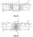
- the engine 10 may include a housing or cylinder 14, one or more pistons 16, outlet ports 18, inlet ports 20, and at least one fuel injector or nozzle 22. With reference to FIG. 3B , while four cylinders 14 are shown, it will be appreciated that the engine 10 may include any number of cylinders 14, each including at least one piston 16, as is known in the art. As illustrated in FIG. 1 , in one configuration, each cylinder 14 of the engine 10 may include two pistons 16.
- the cylinder 14 may be formed from a material such as iron, steel, or a suitable metallic alloy, and may extend along a longitudinal axis A1.
- the longitudinal axis A1 may be a central longitudinal axis A1, such that the cylinder 14 is symmetrically disposed about the longitudinal axis A1.
- the cylinder 14 may also include a transverse axis A2 extending in a direction substantially perpendicular to the longitudinal axis A1.
- a bore or passage 26 may extend through, or otherwise be defined by, the cylinder 14 along the longitudinal axis A1.
- the outlet ports 18 and the inlet ports 20 may be configured to fluidly communicate with the passage 26.
- the inlet ports 20 can be configured to deliver air (e.g., ambient air, air from a turbocharger or other portion of an exhaust gas regeneration system (not shown), etc.) to the passage 26 for combustion, while the outlet ports 18 can be configured to remove exhaust gases from the passage 26 after combustion.
- air e.g., ambient air, air from a turbocharger or other portion of an exhaust gas regeneration system (not shown), etc.
- the pistons 16 may be slidably disposed in the passage 26 of the cylinder 14 for opposed, reciprocating motion along the longitudinal axis A1.
- Each piston 16 may include a skirt 28 and a bowl or crown 30.
- the skirt 28 can be integrally or monolithically formed with the crown 30.
- the crown 30 may include an end surface 32 having, or otherwise defining, a recess 34.
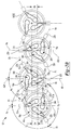
- the recess 34 may include one or more portions or lobes 36. While the recess 34 is illustrated to include first, second, and third lobes 36a, 36b, 36c, the recess 34 may also include greater than or less than three lobes 36. In this regard, it will be appreciated that the number of lobes 36 may correspond to, or otherwise equal, the number of nozzles 22.
- the first lobe 36a may be substantially similar to the second and third lobes 36b, 36c, apart from any exceptions described below and/or shown in the figures. Accordingly, except as otherwise provided, references herein to the lobe 36 will be understood to apply equally to the first, second, and third lobes 36a, 36b, 36c, and like reference numerals may be used to describe similar features of the first, second, and third lobes 36a, 36b, 36c.
- the lobe 36 may extend along a lobe center line 40 and include a tip or nose 42, first and second flank surfaces 44, 46 and a base or heel 48.
- the lobe 36 including the nose 42, the first and second flank surfaces 44, 46, and the heel 48, can be collectively defined by a lobe surface 50 having a concave shape or profile.
- the nose 42 may be configured to fluidly communicate with the nozzle 22.
- an outer peripheral surface 51 of the piston 16 may include an aperture or opening 53 in fluid communication with the lobe 36.
- the nozzle 22 may inject fuel into the nose 42 of the lobe 36 through the opening 53.
- the lobe center line 40 may intersect, or otherwise extend from, the nozzle 22, such that fuel injected from the nozzle 22 and into the nose 42 generally travels along the lobe center line 40.
- the lobe center line 40 may extend through a central point 49 on a distal end 55 of the nozzle.
- the nozzle 22 may inject fuel into the cylinder 14 from the central point 49 and generally along the center line 40.
- the first and second flank surfaces 44, 46 may extend from the end surface 32 of the crown 30, and from and between the nose 42 and the heel 46. In this regard, as illustrated in FIG.
- the first and second flank surfaces 44, 46 may oppose, or otherwise face, one another, and define an angle ⁇ therebetween.
- the first and second flank surfaces 44, 46 may be generally parallel, such that the angle ⁇ is substantially equal to zero. In other configurations, the angle ⁇ may be greater than zero degrees and less than 40 degrees.
- the heel 48 of the lobe 36 may include a radially outer surface or side 52 and a radially inner surface or side 54.
- the radially outer surface 52 may extend from the end surface 32 and define a generally concave shape.
- the lobe center line 40a of the first lobe 36a may intersect the lobe center line 40b of the second lobe 36b
- the lobe center line 40b of the second lobe 36b may intersect the lobe center line 40c of the third lobe 36c
- the lobe center line 40c of the third lobe 36c may intersect the lobe center line 40a of the first lobe 36a, such that a portion of the radially outer surfaces 52a, 52b, 52c of the first, second and third lobes 36a, 36b, 36c collectively define a substantially circular profile or shape 57.
- the radially outer surfaces 52a, 52b, 52c may collectively define the circular profile or shape 57 having flank surfaces 44, 46 projecting radially outward therefrom.
- the lobe center lines 40a, 40b, 40c may intersect one another such that the radially outer surfaces 52a, 52b, 52c of the first, second and third lobes 36a, 36b, 36c may collectively define other shapes, including a trefoil or other multi-lobed shape.
- the radially inner side 54 may extend from the end surface 32 and define a generally concave shape. As illustrated, the radially inner side 54a of the first lobe 36a may open into, or otherwise communicate with, the radially inner sides 54b, 54c of the second and third lobes 36b, 36c. Similarly, the radially inner side 54b of the second lobe 36b may open into, or otherwise communicate with, the radially inner sides 54a, 54c of the first and third lobes 36a, 36c, and the radially inner side 54c of the third lobe 36c may open into, or otherwise communicate with, the radially inner sides 54a, 54b of the first and second lobes 36a, 36b. In this regard, it will be appreciated that the radially inner sides 54a, 54b, 54c may each communicate at, and with, a central portion of the recess 34, which may be referred to as a mixing surface 56.
- the mixing surface 56 may extend from and between the end surface 32 of the crown 30 and the lobe surface 50 of the first, second and third lobes 36a, 36b, 36c.
- the mixing surface 56 may include first, second, and third branches 56a, 56b, 56c extending radially outward from a central portion 58 of the mixing surface 56.
- the lobe surfaces 50a, 50b, 50c and the mixing surface 56 may collectively define the recess 34.
- the recess 34 may define a portion of a sphere.
- the lobe center lines 40a, 40b, 40c may intersect one another such that in some configurations the recess 34 may define a substantially hemispherical shape that may be symmetrically disposed about the longitudinal axis A1.
- the lobe surface 50 and the mixing surface 56 can help to ensure proper mixing of the fuel when it is injected by the nozzles 22.
- the recess 34 of a first piston 16a may face the recess 34 of a second piston 16b.
- the first and second pistons 16a, 16b may be disposed within the passage 26 such that the first, second, and third lobes 36a, 36b, 36c of the first piston 16a are aligned with the first, second, and third lobes 36a, 36b, 36c, respectively, of the second piston 16b.
- the recess 34 of the first piston 16a may cooperate with the recess 34 of the second piston 16b to at least partially define a combustion chamber therebetween.
- the first lobe 36a of the first piston 16a and the first lobe 36a of the second piston 16b may define a first volume 60a
- the second lobe 36a of the first piston 16a and the second lobe 36a of the second piston 16b may define a second volume 60b
- the third lobe 36a of the first piston 16a and the third lobe 36a of the second piston 16b may define a third volume 60b.
- Each of the first, second, and third volumes 60a, 60b, 60c may be distinct from the other(s) of the first, second, and third volumes.
- the first, second, and third volumes 60a, 60b, 60c may be symmetrically disposed relative to the longitudinal axis A1.
- first, second, and third volumes 60a, 60b, 60c may be symmetrically disposed relative to a cross section of the engine 10 intersecting the longitudinal axis A2, and symmetrically disposed relative to a cross section of the engine 10 intersecting the transverse axis A1.
- first, second, and third lobes 36a, 36b, 36c of the first piston 16a may be offset from, and/or have a different shape or profile than the first, second, and third lobes 36a, 36b, 36c of the second piston 16b, such that the lobes 36a, 36b, 36c and/or the volumes 60a, 60b, 60c are asymmetrically disposed relative to the cross section of the engine 10 intersecting the longitudinal axis A1, and/or asymmetrically disposed relative to the cross section of the engine 10 intersecting the transverse axis A2.
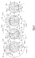
- the first piston 16a of a first cylinder 14a may be angularly offset relative to the orientation of the first piston 16a of a second cylinder 14b.
- the first piston 16a of a third cylinder 14c may be angularly offset relative to the orientation of the first piston 16a of the second cylinder 14b.
- the first piston 16a of the second cylinder 14b may be rotated by a first angle ⁇ b about the longitudinal axis A1b of the second cylinder 14b relative to the orientation of the first piston 16a of the first cylinder 14a about the longitudinal axis A1a of the first cylinder 14a.
- first piston 16a of the third cylinder 14c may be rotated by a second angle (not shown) about the longitudinal axis A1c of the third cylinder 14c relative to the orientation of the first piston 16a of the second cylinder 14b about the longitudinal axis A1b of the second cylinder 14b.
- first angle ⁇ b may be substantially equal to the second angle, such that the first piston 16a of the first cylinder 14a is substantially angularly aligned with the first piston 16a of the third cylinder 14c relative to, or about, the longitudinal axes A1a and A1c.
- the second pistons 16b of the first, second, and third cylinders 14a, 14b, 14c may also be angularly offset from one another as described above with respect to the first pistons 16a.
- each piston 16 may be supported by, or otherwise coupled to, a connecting rod 62.
- the connecting rod 62 can be supported by, or otherwise coupled to, a crankshaft (not shown).
- the nozzle 22 can be disposed within, or otherwise extend through, the cylinder 14. As illustrated in FIG. 3B , in some configurations each nozzle 22 is offset from an adjacent nozzle 22 by an angle ⁇ about the longitudinal axis A1. Specifically, the first nozzle 22a may extend from the cylinder 14 along an axis Xa, the second nozzle 22b may extend from the cylinder along an axis Xb, and the third nozzle 22c may extend from the cylinder along an axis Xc.
- the axis Xa may be offset from the axis Xb by an angle ⁇ a
- the axis Xb may be offset from the axis Xc by an angle ⁇ b
- the axis Xc may be offset from the axis Xa by an angle ⁇ c.
- the angle ⁇ a may be substantially equal to the angle ⁇ b
- the angle ⁇ b may be substantially equal to the angle ⁇ c, such that the nozzles 22a, 22b and 22c are symmetrically disposed about the longitudinal axis A1.
- ⁇ a, ⁇ b, and ⁇ c may each be equal to an angle between 100 degrees and 140 degrees.
- ⁇ a, ⁇ b, and ⁇ c may each be equal to 120 degrees. It will also be appreciated that the angle ⁇ a may differ from the angle ⁇ b, and/or the angle ⁇ b may differ from the angle ⁇ c.
- the nozzles 22 may be in fluid communication with the passage 26.
- the nozzles 22 can be configured to spray or otherwise deliver a volume of fuel to the volumes 60a, 60b, 60c for combustion.
- the nozzles 22a, 22b, 22c may deliver the volume of fuel in a direction substantially along or parallel to the axes Xa, Xb, Xc, respectively.
- the volume of fuel may be delivered in a direction that is offset from the axes Xa, Xb, Xc.
- the first nozzle 22a may be configured to deliver the volume of fuel in a direction substantially along or parallel to the centerline 40a
- the second nozzle 22b may be configured to deliver the volume of fuel in a direction substantially along or parallel to the centerline 40b
- the third nozzle 22c may be configured to deliver the volume of fuel in a direction substantially along or parallel to the centerline 40c.
- the cylinders 14 may be positioned within the engine 10 such that the longitudinal axes A1 are substantially parallel to each other.
- the longitudinal axis A1a of the first cylinder 14a may also be offset from the longitudinal axis A1b of the second cylinder 14b that is adjacent to the first cylinder 14a.
- the longitudinal axis A1b may be offset in a first direction from the longitudinal axis A1a by a distance Da.
- the longitudinal axis A1c of the third cylinder 14c, that is adjacent to the second cylinder 14b may be offset in a second direction from the longitudinal axis A1b by a distance Db.
- the second direction may be opposite the first direction.
- the distance Db may be substantially equal to the distance Da, such that the longitudinal axis A1c is aligned or otherwise coplanar with the longitudinal axis A1b.
- the engine 10 may include any number (N) of cylinders 14.
- each cylinder 14(N) may be offset from an adjacent cylinder 14(N-1) by the distance Da, and offset from an adjacent cylinder 14(N+1) by the distance Db.
- the first piston 16a and the nozzles 22a, 22b, 22c of the first cylinder 14a may be angularly offset about the longitudinal axis A1a relative to the first piston 16a and the the nozzles 22a, 22b, 22c, respectively, of the second cylinder 14b.
- the first piston 16a and the first nozzle 22a of the second cylinder 14b may be angularly offset about the longitudinal axis A1b relative to the orientation of the first piston 16a and the first nozzle 22a of the first cylinder 14a about the longitudinal axis A1a.
- the opening 53a of the first piston 16a and the axis Xa of the first nozzle 22a of the first cylinder 14a may be substantially aligned with the transverse axis A2a of the first cylinder 14a, while the opening 53a of the first piston 16a and the axis Xa of the first nozzle 22a of the second cylinder 14b may be offset from the transverse axis A2b of the second cylinder 14b by the angle ⁇ b.
- the opening 53b of the first piston 16a and the axis Xb of the second nozzle 22b of the first cylinder 14a may be offset from the transverse axis A2a of the first cylinder 14a by the angle ⁇ a, while the opening 53b of the first piston 16a and the axis Xb of the second nozzle 22b of the second cylinder 14b may be substantially aligned with the transverse axis A2b of the second cylinder 14b.
- the opening 53c of the first piston 16a and the axis Xc of the third nozzle 22c of the first cylinder 14a may be offset from the transverse axis A2a of the first cylinder 14a by the angle ⁇ c
- the opening 53c of the first piston 16a and the axis Xc of the third nozzle 22c of the second cylinder 14b may be offset from the transverse axis A2b of the second cylinder 14b by an angle ⁇ c.
- the angles ⁇ a, ⁇ b, and ⁇ c may be substantially equal to each other.
- the angle ⁇ b may be between 45 and 75 degrees, and in some configurations, substantially equal to 60 degrees.
- the angle ⁇ c may be between 45 and 75 degrees, and in some configurations, substantially equal to 60 degrees.
- the configuration of the cylinders 14 and the pistons 16, including the distances Da and Db, the configuration of the nozzles 22a, 22b, 22c and the lobe centerlines 40a, 40b, 40c, including the angles ⁇ and ⁇ , and the configuration of the pistons 16a, 16b, can allow for the closest possible arrangement of the cylinders 14 within the engine 10 having three nozzles 22.
- arranging the cylinders 14, the pistons 16, and the nozzles 22a, 22b, 22c in the manner described can help to prevent the nozzles 22a, 22b, 22c from contacting or otherwise interfering with an adjacent cylinder 14 and/or the nozzles 22a, 22b, 22c of the adjacent cylinder 14, thus allowing for a reduction in the size of the engine 10.
- the inclusion of three nozzles 22, and the configuration of the recess 34 and the first, second and third lobes 36a, 36b, 36c within the engine 10, can help to ensure improved combustion performance, including efficient utilization and combustion of air within the combustion chamber, as well as the efficient mixing of fuel from each of the nozzles 22 within the combustion chamber.
- FIG. 4 another example of an engine is labelled 10a.
- the engine 10a is substantially similar to the engine 10 such that only differences between the engines 10, 10a will now be described.
- the longitudinal axis A1b of the second cylinder 14b is offset in a first direction from the longitudinal axis A1a of the first cylinder 14a.
- the longitudinal axis A1c of the third cylinder 14c is offset in a second direction from the longitudinal axis A1b, where the second direction is opposite from the first direction.
- the longitudinal axes A1a, A1b, A1c, of the first, second, and third cylinders 14a, 14b, and 14c are aligned with one another such that the longitudinal axes A1a, A1b, A1c all lie within the same plane.
- the angles ⁇ a, ⁇ b, and ⁇ c between the axes Xa, Xb, Xc of the nozzles 22a, 22b, 22c are each equal to 120 degrees.
- the nozzles 22a, 22b, 22c are symmetrically disposed about the longitudinal axes A1a, A1b, A1c of the first, second, and third cylinders 14a, 14b, 14c.
- the angle ⁇ a between the first and second nozzles 22a and 22b is less than the angle ⁇ b between the second and third nozzles 22b and 22c and less than the angle ⁇ c between the first and third nozzles 22a and 22c.
- the angles ⁇ b and ⁇ c are equal to each other such that the distal ends of the nozzles 22a, 22b, 22c form an isosceles triangle 64.
- the angle ⁇ a is between 60 degrees and 120 degrees (e.g., 70 degrees), and each of the angles ⁇ b and ⁇ c are between 150 degrees and 120 degrees (e.g., 145 degrees).
- each of the angles ⁇ b and ⁇ c may be determined by subtracting the angle ⁇ a from 360 degrees and dividing the result by two.
- the shape of the crown 30 of the pistons 16 in the engine 10a is different than the shape of the crown 30 of the pistons 16 in the engine 10.
- the lobe centerlines 40a, 40b, 40c are angularly offset relative to the nozzle axes Xa, Xb, Xc, respectively.
- the lobe centerlines 40a, 40b, 40c are aligned or collinear with the axes Xa, Xb, Xc, respectively.
- FIGS. 4 and 5 the engine 10a shown in FIGS.
- the shapes of the lobes 36a, 36b, 36c are asymmetric with respect to the lobe centerlines 40a, 40b, 40c, respectively.
- the shapes of the lobes 36a, 36b, 36c are symmetric with respect to the lobe centerlines 40a, 40b, 40c, respectively.
- Example embodiments are provided so that this disclosure will be thorough, and will fully convey the scope to those who are skilled in the art. Numerous specific details are set forth such as examples of specific components, devices, and methods, to provide a thorough understanding of embodiments of the present disclosure. It will be apparent to those skilled in the art that specific details need not be employed, that example embodiments may be embodied in many different forms and that neither should be construed to limit the scope of the disclosure. In some example embodiments, well-known processes, well-known device structures, and well-known technologies are not described in detail.
- first, second, third, etc. may be used herein to describe various elements, components, regions, layers and/or sections, these elements, components, regions, layers and/or sections should not be limited by these terms. These terms may be only used to distinguish one element, component, region, layer or section from another region, layer or section. Terms such as “first,” “second,” and other numerical terms when used herein do not imply a sequence or order unless clearly indicated by the context. Thus, a first element, component, region, layer or section discussed below could be termed a second element, component, region, layer or section without departing from the teachings of the example embodiments.
- spatially relative terms such as “inner,” “outer,” “beneath,” “below,” “lower,” “above,” “upper,” and the like, may be used herein for ease of description to describe one element or feature's relationship to another element(s) or feature(s) as illustrated in the figures.
- Spatially relative terms may be intended to encompass different orientations of the device in use or operation in addition to the orientation depicted in the figures. For example, if the device in the figures is turned over, elements described as “below” or “beneath” other elements or features would then be oriented “above” the other elements or features.
- the example term “below” can encompass both an orientation of above and below.
- the device may be otherwise oriented (rotated 90 degrees or at other orientations) and the spatially relative descriptors used herein interpreted accordingly.
Landscapes
- Engineering & Computer Science (AREA)
- Mechanical Engineering (AREA)
- General Engineering & Computer Science (AREA)
- Chemical & Material Sciences (AREA)
- Combustion & Propulsion (AREA)
- Pistons, Piston Rings, And Cylinders (AREA)
- Combustion Methods Of Internal-Combustion Engines (AREA)
Applications Claiming Priority (2)
| Application Number | Priority Date | Filing Date | Title |
|---|---|---|---|
| US201562121879P | 2015-02-27 | 2015-02-27 | |
| US15/050,945 US10161371B2 (en) | 2015-02-27 | 2016-02-23 | Opposed piston three nozzle piston bowl design |
Publications (1)
| Publication Number | Publication Date |
|---|---|
| EP3061908A1 true EP3061908A1 (fr) | 2016-08-31 |
Family
ID=55661088
Family Applications (1)
| Application Number | Title | Priority Date | Filing Date |
|---|---|---|---|
| EP16157539.4A Withdrawn EP3061908A1 (fr) | 2015-02-27 | 2016-02-26 | Conception du cylindre de piston de buse de trois pistons opposés |
Country Status (2)
| Country | Link |
|---|---|
| US (1) | US10161371B2 (fr) |
| EP (1) | EP3061908A1 (fr) |
Families Citing this family (5)
| Publication number | Priority date | Publication date | Assignee | Title |
|---|---|---|---|---|
| US10066590B2 (en) * | 2015-02-27 | 2018-09-04 | Avl Powertrain Engineering, Inc. | Opposed piston three nozzle combustion chamber design |
| US10161371B2 (en) | 2015-02-27 | 2018-12-25 | Avl Powertrain Engineering, Inc. | Opposed piston three nozzle piston bowl design |
| US11085297B1 (en) * | 2016-02-24 | 2021-08-10 | Enginuity Power Systems, Inc | Opposed piston engine and elements thereof |
| US10989109B2 (en) * | 2018-07-18 | 2021-04-27 | Warren Engine Company | Fuel ignition methods for opposed piston engines and related structures |
| US11085413B2 (en) * | 2018-11-01 | 2021-08-10 | Enginaity Power Systems, Inc | Ignition source adapted for positioning within a combustion chamber |
Citations (4)
| Publication number | Priority date | Publication date | Assignee | Title |
|---|---|---|---|---|
| US1143408A (en) * | 1913-01-18 | 1915-06-15 | Gen Electric | Internal-combustion engine. |
| WO2011061191A1 (fr) * | 2009-11-18 | 2011-05-26 | Otto Daude | Procédé d'injection de carburant pour moteurs diesel comportant des injecteurs disposés de façon tangentielle à la périphérie du cylindre |
| WO2012158756A1 (fr) * | 2011-05-18 | 2012-11-22 | Achates Power, Inc. | Structure de chambre de combustion pour moteurs à pistons opposés |
| GB2493260A (en) * | 2011-07-26 | 2013-01-30 | Ecomotors Internat Inc | Opposed piston engine with tumble flow in shaped combustion chamber |
Family Cites Families (57)
| Publication number | Priority date | Publication date | Assignee | Title |
|---|---|---|---|---|
| US1127772A (en) | 1913-01-02 | 1915-02-09 | Hugo Junkers | Internal-combustion engine. |
| US1486583A (en) | 1923-01-26 | 1924-03-11 | William M Huskisson | Internal-combustion engine |
| US2463418A (en) | 1942-04-30 | 1949-03-01 | Pescara Raul Pateras | Fuel injection system |
| US3007462A (en) | 1957-08-26 | 1961-11-07 | Vernon W Balzer | Reciprocating machine |
| GB1014831A (en) | 1961-06-26 | 1965-12-31 | James Abraham Hardman | Improvements in or relating to internal combustion engines |
| US3407790A (en) | 1967-04-12 | 1968-10-29 | Anker K. Antonsen | Uniflow scavenged engine having improved gaseous fuel admission |
| FR2145081A5 (fr) | 1971-07-08 | 1973-02-16 | Peugeot & Renault | |
| DE2500644C2 (de) | 1975-01-09 | 1988-07-07 | Klöckner-Humboldt-Deutz AG, 5000 Köln | Kraftstoffeinspritzventil für Brennkraftmaschinen |
| US4043301A (en) | 1975-06-20 | 1977-08-23 | Templet Industries Incorporated | Internal combustion engine |
| DE2849783A1 (de) | 1978-04-25 | 1979-11-08 | Charles Gwin Renegar | Verbrennungskraftmaschine mit gegenueberliegenden, gefuehrten kolben und nockenantrieben |
| US4709679A (en) | 1985-03-25 | 1987-12-01 | Stanadyne, Inc. | Modular accumulator injector |
| US4872433A (en) | 1987-12-07 | 1989-10-10 | Paul Marius A | Combustion chamber configurations for two cycle engines |
| US5042441A (en) | 1989-10-03 | 1991-08-27 | Paul Marius A | Low emission combustion system for internal combustion engines |
| IT1288748B1 (it) | 1996-10-11 | 1998-09-24 | Iveco Fiat | Iniettore di combustibile per un motore endotermico e motore endotermico provvisto di tale iniettore |
| US6170443B1 (en) | 1998-09-11 | 2001-01-09 | Edward Mayer Halimi | Internal combustion engine with a single crankshaft and having opposed cylinders with opposed pistons |
| DE19937713C1 (de) | 1999-08-10 | 2001-03-15 | Siemens Ag | Steuerventilanordnung zum Einsatz in einem Kraftstoffinjektor für Verbrennungsmotoren |
| ITPZ990004A1 (it) | 1999-10-04 | 2001-04-04 | Cosimo Sarno | Sistemi pluri-iniettori. |
| US6526927B1 (en) | 2000-10-03 | 2003-03-04 | Dennis C. Palmer | Internal combustion engine |
| US6595188B2 (en) | 2001-12-04 | 2003-07-22 | Caterpillar Inc | Compact valve assembly and fuel injector using same |
| JP4576884B2 (ja) | 2004-05-19 | 2010-11-10 | トヨタ自動車株式会社 | 内燃機関の制御装置および制御方法 |
| US7360511B2 (en) | 2004-06-10 | 2008-04-22 | Achates Power, Inc. | Opposed piston engine |
| US7334570B2 (en) | 2005-04-01 | 2008-02-26 | Achates Power, Inc. | Common rail fuel injection system with accumulator injectors |
| JP2009103085A (ja) | 2007-10-25 | 2009-05-14 | Suzuki Motor Corp | 2サイクルエンジンの燃料噴射制御装置 |
| DE102007056913A1 (de) | 2007-11-26 | 2009-05-28 | Robert Bosch Gmbh | Einspritzdüse für Kraftstoff mit Kugelventil |
| US8474435B2 (en) * | 2008-09-04 | 2013-07-02 | Achates Power, Inc. | Opposed piston, compression ignition engine with single-side mounted crankshafts and crossheads |
| US8151747B2 (en) | 2009-04-07 | 2012-04-10 | Scuderi Group, Llc | Crescent-shaped recess in piston of a split-cycle engine |
| US10180115B2 (en) | 2010-04-27 | 2019-01-15 | Achates Power, Inc. | Piston crown bowls defining combustion chamber constructions in opposed-piston engines |
| EP2547868B1 (fr) | 2010-04-27 | 2016-08-03 | Achates Power, Inc. | Types de chambre de combustion pour moteurs à pistons opposés |
| US9512779B2 (en) | 2010-04-27 | 2016-12-06 | Achates Power, Inc. | Swirl-conserving combustion chamber construction for opposed-piston engines |
| US8997710B2 (en) | 2010-05-18 | 2015-04-07 | Achates Power, Inc. | Fuel injector support constructions for direct injection opposed-piston engines |
| EP2606202B1 (fr) | 2010-08-16 | 2016-03-09 | Achates Power, Inc. | Formes de jet d'injection de carburant pour des moteurs à pistons opposés |
| JP5161278B2 (ja) | 2010-09-22 | 2013-03-13 | 日立オートモティブシステムズ株式会社 | 内燃機関の燃料噴射制御装置 |
| US20120192831A1 (en) * | 2011-01-27 | 2012-08-02 | Ecomotors International, Inc. | Combustion Chamber for a Side-Mounted Direction Injector |
| DE102011101005A1 (de) | 2011-04-20 | 2012-10-25 | Daimler Ag | Kolben für eine Hubkolben-Brennkraftmaschine |
| US9631569B2 (en) | 2014-08-04 | 2017-04-25 | General Electric Company | System and method for controlling operation of an engine |
| GB2491155B (en) | 2011-05-24 | 2013-04-10 | Cox Powertrain Ltd | Opposed piston engine having injector located within cylinder |
| GB2493061A (en) | 2011-07-15 | 2013-01-23 | Ecomotors Internat Inc | Opposed piston engine with toroidal combustion chamber |
| US20130036999A1 (en) | 2011-08-08 | 2013-02-14 | Ecomotors International, Inc. | High-Squish Combustion Chamber With Side Injection |
| US20130104848A1 (en) | 2011-10-27 | 2013-05-02 | Achates Power, Inc. | Fuel Injection Strategies in Opposed-Piston Engines with Multiple Fuel Injectors |
| DE102012111776A1 (de) | 2011-12-09 | 2013-06-13 | Ecomotors International, Inc. | Gegenkolbenmotor mit ringförmiger Brennkammer mit Seiteneinspritzung |
| US8783015B2 (en) | 2011-12-15 | 2014-07-22 | Ecomotors, Inc. | Shared EGR system and method for a dual-module engine |
| CN102588075A (zh) | 2012-03-13 | 2012-07-18 | 深圳市世纪经纬数据系统有限公司 | 一种缸内多点喷射的内燃机 |
| JP5984469B2 (ja) | 2012-04-11 | 2016-09-06 | 三菱重工業株式会社 | 二元燃料ディーゼルエンジン |
| DE202012012843U1 (de) | 2012-04-18 | 2014-07-01 | Ecomotors, Inc. | Symmetrischer Motor mit gegenüberliegenden Kolben und gegenüberliegenden Zylindern |
| EP2672101A1 (fr) | 2012-06-05 | 2013-12-11 | Caterpillar Motoren GmbH & Co. KG | Buse d'injection |
| DE102012210937A1 (de) | 2012-06-27 | 2014-01-23 | Robert Bosch Gmbh | Verfahren zur Steuerung einer Brennkraftmaschine und System mit einer Brennkraftmaschine und einem Steuergerät |
| JP5869443B2 (ja) | 2012-07-27 | 2016-02-24 | 本田技研工業株式会社 | 内燃機関のピストン構造 |
| DE112013000183B4 (de) | 2012-08-24 | 2020-03-12 | Mazda Motor Corp. | Brennkammeraufbau für einen Motor |
| WO2014052126A1 (fr) | 2012-09-25 | 2014-04-03 | Achates Power, Inc. | Injection de carburant avec formes de jet à tourbillon dans des moteurs à pistons opposés |
| JP5652466B2 (ja) | 2012-12-21 | 2015-01-14 | トヨタ自動車株式会社 | 内燃機関のピストン及び内燃機関 |
| GB2515254B (en) | 2013-04-05 | 2016-07-20 | Osp Engines Ltd | Opposed stepped piston engine power cylinder lubrication system |
| CN105492736B (zh) | 2013-08-05 | 2020-01-14 | 阿凯提兹动力公司 | 用于具有成形的燃烧室的对置活塞发动机的双燃料构造 |
| US9211797B2 (en) | 2013-11-07 | 2015-12-15 | Achates Power, Inc. | Combustion chamber construction with dual mixing regions for opposed-piston engines |
| JP6384657B2 (ja) | 2014-06-30 | 2018-09-05 | 三菱自動車工業株式会社 | 燃料噴射制御装置 |
| US9903270B2 (en) * | 2014-08-01 | 2018-02-27 | Avl Powertrain Engineering, Inc. | Cylinder arrangement for opposed piston engine |
| GB2530761A (en) | 2014-10-01 | 2016-04-06 | Delphi Internat Operations Luxembourg S Ã R L | Fuel injection equipment |
| US10161371B2 (en) | 2015-02-27 | 2018-12-25 | Avl Powertrain Engineering, Inc. | Opposed piston three nozzle piston bowl design |
-
2016
- 2016-02-23 US US15/050,945 patent/US10161371B2/en not_active Expired - Fee Related
- 2016-02-26 EP EP16157539.4A patent/EP3061908A1/fr not_active Withdrawn
Patent Citations (4)
| Publication number | Priority date | Publication date | Assignee | Title |
|---|---|---|---|---|
| US1143408A (en) * | 1913-01-18 | 1915-06-15 | Gen Electric | Internal-combustion engine. |
| WO2011061191A1 (fr) * | 2009-11-18 | 2011-05-26 | Otto Daude | Procédé d'injection de carburant pour moteurs diesel comportant des injecteurs disposés de façon tangentielle à la périphérie du cylindre |
| WO2012158756A1 (fr) * | 2011-05-18 | 2012-11-22 | Achates Power, Inc. | Structure de chambre de combustion pour moteurs à pistons opposés |
| GB2493260A (en) * | 2011-07-26 | 2013-01-30 | Ecomotors Internat Inc | Opposed piston engine with tumble flow in shaped combustion chamber |
Also Published As
| Publication number | Publication date |
|---|---|
| US10161371B2 (en) | 2018-12-25 |
| US20160252067A1 (en) | 2016-09-01 |
Similar Documents
| Publication | Publication Date | Title |
|---|---|---|
| EP3061908A1 (fr) | Conception du cylindre de piston de buse de trois pistons opposés | |
| US8783218B2 (en) | Toroidal combustion chamber with side injection | |
| US9938927B2 (en) | Piston | |
| US7185614B2 (en) | Double bowl piston | |
| US8991370B2 (en) | Intake apparatus of engine | |
| US20160053668A1 (en) | Prechamber assembly for engine | |
| EP3140527B1 (fr) | Chambre de combustion pour moteur à combustion interne, et moteur à combustion interne | |
| US20130092123A1 (en) | Combustion system for an engine having multiple fuel spray induced vortices | |
| US8997721B2 (en) | Intake apparatus of engine | |
| CN107917011B (zh) | 用于内燃发动机的气缸盖 | |
| US9903270B2 (en) | Cylinder arrangement for opposed piston engine | |
| KR970703480A (ko) | 통내분사형 내연기관 | |
| EP3061906B1 (fr) | Conception de chambre de combustion à pistons opposés et trois buses | |
| US10961899B2 (en) | Internal combustion engine | |
| EP2940281B1 (fr) | Culasse et moteur | |
| US9004047B2 (en) | Engine assembly having a baffle in the intake manifold | |
| WO2005088102A1 (fr) | Procede destine a determiner une voie pour une came d'un moteur a came et partie de voie de bosse, came dont la voie est determine par ce procede et moteur a came possedant une partie de voie de bosse | |
| WO2006024082A3 (fr) | Moteur a combustion interne a soupape rotative | |
| US20160252013A1 (en) | Piston Crown and Corresponding Port Geometry | |
| US10344705B2 (en) | Intake valve fairing for a cylinder head of an engine | |
| GB1560430A (en) | Internal combustion engines | |
| US20160032822A1 (en) | Cylinder arrangement for opposed piston two-stroke engine | |
| JP6134700B2 (ja) | 内燃エンジン用シリンダヘッド構成 | |
| US6973899B2 (en) | Stratified air scavenged two-cycle engine with air flow | |
| CN101387218B (zh) | 发动机组件、火花点燃的直接喷射燃料系统和方法 |
Legal Events
| Date | Code | Title | Description |
|---|---|---|---|
| PUAI | Public reference made under article 153(3) epc to a published international application that has entered the european phase |
Free format text: ORIGINAL CODE: 0009012 |
|
| AK | Designated contracting states |
Kind code of ref document: A1 Designated state(s): AL AT BE BG CH CY CZ DE DK EE ES FI FR GB GR HR HU IE IS IT LI LT LU LV MC MK MT NL NO PL PT RO RS SE SI SK SM TR |
|
| AX | Request for extension of the european patent |
Extension state: BA ME |
|
| STAA | Information on the status of an ep patent application or granted ep patent |
Free format text: STATUS: REQUEST FOR EXAMINATION WAS MADE |
|
| 17P | Request for examination filed |
Effective date: 20170222 |
|
| RBV | Designated contracting states (corrected) |
Designated state(s): AL AT BE BG CH CY CZ DE DK EE ES FI FR GB GR HR HU IE IS IT LI LT LU LV MC MK MT NL NO PL PT RO RS SE SI SK SM TR |
|
| STAA | Information on the status of an ep patent application or granted ep patent |
Free format text: STATUS: EXAMINATION IS IN PROGRESS |
|
| 17Q | First examination report despatched |
Effective date: 20171026 |
|
| STAA | Information on the status of an ep patent application or granted ep patent |
Free format text: STATUS: THE APPLICATION IS DEEMED TO BE WITHDRAWN |
|
| 18D | Application deemed to be withdrawn |
Effective date: 20240903 |