EP3061569A2 - Systeme und vakuumspannfutter zum transfer von flexiblen länglichen körpern - Google Patents
Systeme und vakuumspannfutter zum transfer von flexiblen länglichen körpern Download PDFInfo
- Publication number
- EP3061569A2 EP3061569A2 EP16155112.2A EP16155112A EP3061569A2 EP 3061569 A2 EP3061569 A2 EP 3061569A2 EP 16155112 A EP16155112 A EP 16155112A EP 3061569 A2 EP3061569 A2 EP 3061569A2
- Authority
- EP
- European Patent Office
- Prior art keywords
- vacuum
- flexible elongate
- vertically oriented
- elongate body
- chuck
- Prior art date
- Legal status (The legal status is an assumption and is not a legal conclusion. Google has not performed a legal analysis and makes no representation as to the accuracy of the status listed.)
- Granted
Links
Images





Classifications
-
- B—PERFORMING OPERATIONS; TRANSPORTING
- B64—AIRCRAFT; AVIATION; COSMONAUTICS
- B64F—GROUND OR AIRCRAFT-CARRIER-DECK INSTALLATIONS SPECIALLY ADAPTED FOR USE IN CONNECTION WITH AIRCRAFT; DESIGNING, MANUFACTURING, ASSEMBLING, CLEANING, MAINTAINING OR REPAIRING AIRCRAFT, NOT OTHERWISE PROVIDED FOR; HANDLING, TRANSPORTING, TESTING OR INSPECTING AIRCRAFT COMPONENTS, NOT OTHERWISE PROVIDED FOR
- B64F5/00—Designing, manufacturing, assembling, cleaning, maintaining or repairing aircraft, not otherwise provided for; Handling, transporting, testing or inspecting aircraft components, not otherwise provided for
- B64F5/40—Maintaining or repairing aircraft
-
- B—PERFORMING OPERATIONS; TRANSPORTING
- B23—MACHINE TOOLS; METAL-WORKING NOT OTHERWISE PROVIDED FOR
- B23Q—DETAILS, COMPONENTS, OR ACCESSORIES FOR MACHINE TOOLS, e.g. ARRANGEMENTS FOR COPYING OR CONTROLLING; MACHINE TOOLS IN GENERAL CHARACTERISED BY THE CONSTRUCTION OF PARTICULAR DETAILS OR COMPONENTS; COMBINATIONS OR ASSOCIATIONS OF METAL-WORKING MACHINES, NOT DIRECTED TO A PARTICULAR RESULT
- B23Q3/00—Devices holding, supporting, or positioning work or tools, of a kind normally removable from the machine
- B23Q3/02—Devices holding, supporting, or positioning work or tools, of a kind normally removable from the machine for mounting on a work-table, tool-slide, or analogous part
- B23Q3/06—Work-clamping means
- B23Q3/08—Work-clamping means other than mechanically-actuated
- B23Q3/088—Work-clamping means other than mechanically-actuated using vacuum means
-
- B—PERFORMING OPERATIONS; TRANSPORTING
- B25—HAND TOOLS; PORTABLE POWER-DRIVEN TOOLS; MANIPULATORS
- B25B—TOOLS OR BENCH DEVICES NOT OTHERWISE PROVIDED FOR, FOR FASTENING, CONNECTING, DISENGAGING, OR HOLDING
- B25B11/00—Work holders not covered by any preceding group in the subclass, e.g. magnetic work holders, vacuum work holders
- B25B11/005—Vacuum work holders
-
- B—PERFORMING OPERATIONS; TRANSPORTING
- B64—AIRCRAFT; AVIATION; COSMONAUTICS
- B64F—GROUND OR AIRCRAFT-CARRIER-DECK INSTALLATIONS SPECIALLY ADAPTED FOR USE IN CONNECTION WITH AIRCRAFT; DESIGNING, MANUFACTURING, ASSEMBLING, CLEANING, MAINTAINING OR REPAIRING AIRCRAFT, NOT OTHERWISE PROVIDED FOR; HANDLING, TRANSPORTING, TESTING OR INSPECTING AIRCRAFT COMPONENTS, NOT OTHERWISE PROVIDED FOR
- B64F5/00—Designing, manufacturing, assembling, cleaning, maintaining or repairing aircraft, not otherwise provided for; Handling, transporting, testing or inspecting aircraft components, not otherwise provided for
- B64F5/50—Handling or transporting aircraft components
-
- B—PERFORMING OPERATIONS; TRANSPORTING
- B66—HOISTING; LIFTING; HAULING
- B66C—CRANES; LOAD-ENGAGING ELEMENTS OR DEVICES FOR CRANES, CAPSTANS, WINCHES, OR TACKLES
- B66C1/00—Load-engaging elements or devices attached to lifting or lowering gear of cranes or adapted for connection therewith for transmitting lifting forces to articles or groups of articles
- B66C1/02—Load-engaging elements or devices attached to lifting or lowering gear of cranes or adapted for connection therewith for transmitting lifting forces to articles or groups of articles by suction means
- B66C1/0237—Multiple lifting units; More than one suction area
- B66C1/0243—Separate cups
-
- B—PERFORMING OPERATIONS; TRANSPORTING
- B66—HOISTING; LIFTING; HAULING
- B66C—CRANES; LOAD-ENGAGING ELEMENTS OR DEVICES FOR CRANES, CAPSTANS, WINCHES, OR TACKLES
- B66C1/00—Load-engaging elements or devices attached to lifting or lowering gear of cranes or adapted for connection therewith for transmitting lifting forces to articles or groups of articles
- B66C1/02—Load-engaging elements or devices attached to lifting or lowering gear of cranes or adapted for connection therewith for transmitting lifting forces to articles or groups of articles by suction means
- B66C1/0256—Operating and control devices
-
- B—PERFORMING OPERATIONS; TRANSPORTING
- B66—HOISTING; LIFTING; HAULING
- B66C—CRANES; LOAD-ENGAGING ELEMENTS OR DEVICES FOR CRANES, CAPSTANS, WINCHES, OR TACKLES
- B66C1/00—Load-engaging elements or devices attached to lifting or lowering gear of cranes or adapted for connection therewith for transmitting lifting forces to articles or groups of articles
- B66C1/02—Load-engaging elements or devices attached to lifting or lowering gear of cranes or adapted for connection therewith for transmitting lifting forces to articles or groups of articles by suction means
- B66C1/0281—Rectangular or square shape
Definitions
- the present disclosure relates to systems, methods, and vacuum chucks for transferring flexible elongate bodies.
- uncured composite layups may be transferred from a layup tool to a cure mandrel, and deformation of the uncured composite layups during transfer may cause buckling and/or wrinkling of the uncured composite layup. Such bucking and/or wrinkling may be undesirable and/or may require that the uncured composite layup be reworked and/or scrapped.
- the flexible elongate bodies may have various conformations, and it may be desirable to transfer a plurality of different flexible elongate bodies, with differing conformations, utilizing a single, or the same, systems, methods, and/or vacuum chucks.
- stringers for the wings of composite aircraft may vary in shape with a location of a given stringer within the wing of the composite aircraft. Under these conditions, it may be cost-prohibitive to utilize a separate and/or different transfer system to transfer each of the different stringers.
- the vacuum chucks include an elongate rigid support, a vertically oriented vacuum surface, a vacuum manifold, and a skirt seal.
- the vertically oriented vacuum surface includes a plurality of vacuum holes and extends along a length of the elongate rigid support.
- the vertically oriented vacuum surface is supported by the elongate rigid support and is configured to contact a vertical surface of the flexible elongate body during transfer of the flexible elongate body by the vacuum chuck.
- the vacuum manifold is in fluid communication with the plurality of vacuum holes and is configured to apply a retention vacuum to the plurality of vacuum holes to retain the flexible elongate body on the vertically oriented vacuum surface.
- the skirt seal extends along a length of the vertically oriented vacuum surface. The skirt seal may be sized and located to form a fluid seal with the flexible elongate body and/or to resist peeling of the flexible elongate body from the vertically oriented vacuum surface when the flexible elongate body is in contact with the vertically oriented vacuum surface and the retention vacuum is applied to the plurality of vacuum holes.
- the systems include an elongate horizontal support structure and a transfer structure that is configured to support the elongate horizontal support structure.
- the systems further include a plurality of vertical linkages. Each of the plurality of vertical linkages extends between an upper end and a lower end, and the upper end is operatively attached to the elongate horizontal support structure such that the plurality of vertical linkages extends from the elongate horizontal support structure.
- the systems also include a plurality of vacuum chucks. Each of the plurality of vacuum chucks includes a respective lift support that is operatively attached to the lower end of a respective one of the plurality of vertical linkages. Each of the plurality of vacuum chucks is configured to selectively retain a respective portion of the vertical surface of the flexible elongate body.
- the methods include suspending an elongate horizontal support structure with a transfer structure.
- An upper end of each of a plurality of vertical linkages is operatively attached to the elongate horizontal support structure and each of the plurality of vertical linkages extends vertically from the elongate horizontal support structure.
- a respective vacuum chuck of a plurality of vacuum chucks is operatively attached to a lower end of each of the plurality of vertical linkages, and the suspending the elongate horizontal support structure includes suspending the plurality of vacuum chucks.
- the methods further include aligning each of the plurality of vacuum chucks with a respective portion of the vertical surface of the flexible elongate body and selectively actuating each of the plurality of vacuum chucks to retain the respective portion of the vertical surface of the flexible elongate body.
- the methods also include lifting the flexible elongate body via translation of the elongate horizontal support structure such that the flexible elongate body is suspended from the plurality of vacuum chucks.
- Figs. 1-18 provide examples of systems 20, vacuum chucks 100, and/or methods 300, according to the present disclosure, for transferring a flexible elongate body. Elements that serve a similar, or at least substantially similar, purpose are labeled with like numbers in each of Figs. 1-18 , and these elements may not be discussed in detail herein with reference to each of Figs. 1-18 . Similarly, all elements may not be labeled in each of Figs. 1-18 , but reference numerals associated therewith may be utilized herein for consistency. Elements, components, and/or features that are discussed herein with reference to one or more of Figs. 1-18 may be included in and/or utilized with any of Figs. 1-18 without departing from the scope of the present disclosure.
- Fig. 1 is an example of an aircraft 700 that includes a composite structure 800 that may be constructed utilizing systems 20, vacuum chuck 100, and/or methods 300, according to the present disclosure.
- Fig. 2 is an example of a wing 740 that may form a portion of aircraft 700 and includes composite structure 800.
- Aircraft 700 and/or composite structure 800 thereof may include a plurality of flexible elongate bodies 90.
- aircraft 700 may include skin segments 790 that may form, cover, and/or be an outer surface of any suitable portion of aircraft 700 and/or a plurality of stringers 770 that, together with a plurality of frames 780, may support an inner surface of skin segments 790.
- wing 740 may include a plurality of wing stringers 742, which may extend along a length of the wing. Wing 740 also may include a plurality of ribs 744. Wing stringers 742 and ribs 744 together may form and/or define at least a portion of an inner support structure 746 for wing 700, which may support an inner surface 748 of skin segments 790 that cover wing 740. Skin segments 790, stringers 770, frames 780, wing stringers 742, and/or ribs 744 may, at least temporarily and/or during construction thereof, be flexible elongate bodies 90 that may be constructed utilizing systems 20, vacuum chucks 100, and/or methods 300, according to the present disclosure.
- any suitable portion of aircraft 700 may be formed from and/or may be composite structure 800.
- composite structure 800 may form, or form a portion of, an airframe 710, a fuselage 720, a fuselage barrel 730, a wing 740, and/or a stabilizer 750 of aircraft 700.
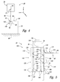
- Fig. 3 is a schematic side view of a system 20, according to the present disclosure, for transferring a flexible elongate body 90.
- Fig. 4 is a schematic cross-sectional view of the system of Fig. 3 taken along line 4-4 of Fig. 3 .
- System 20 includes an elongate horizontal support structure 30 and a transfer structure 40 that is configured to support elongate horizontal support structure 30.
- elongate horizontal support structure 30 may define a longitudinal axis 32 that may extend in a horizontal, or at least substantially horizontal, direction (such as the Y-direction of Fig. 3 ) and/or that may extend parallel to, or at least substantially parallel to, a ground surface 80; however, this specific orientation is not required.
- System 20 further includes a plurality of vertical linkages 50.
- Each vertical linkage 50 has, or extends between, an upper, or first, end 51 and a lower, or second, end 52.
- Upper end 51 is operatively attached to elongate horizontal support structure 30 such that each vertical linkage 50 extends from elongate horizontal support structure 30.
- vertical linkages 50 may extend from elongate horizontal support structure 30 in a vertical, or at least substantially vertical, direction (such as the Z-direction of Figs. 3-4 ) and/or may extend below elongate horizontal support structure 30; however, this specific orientation is not required.
- Each vacuum chuck 100 includes a lift support 104 and is operatively attached to lower end 52 of a respective vertical linkage 50 via lift support 104.
- each vacuum chuck 100 is configured to selectively retain a respective portion of a vertical surface 92 of flexible elongate body 90, as discussed in more detail herein.
- system 20 may be configured to transfer flexible elongate body 90.
- Flexible elongate body 90 may be formed on and/or supported by a support surface 70, and system 20 may be utilized to separate flexible elongate body 90 from support surface 70 and/or to convey flexible elongate body 90 in any suitable direction subsequent to separation from support surface 70.
- support surface 70 include any suitable table, bench, fixture, horizontal support surface, vertical support surface, mandrel, layup mandrel, and/or composite charge layup mandrel.
- elongate horizontal support structure 30 may be aligned with flexible elongate body 90 such that each vacuum chuck 100 is proximal to a respective portion of vertical surface 92. Subsequently, each vacuum chuck 100 may be aligned with and brought into contact with the respective portion of vertical surface 92. Then, a retention vacuum may be applied to each vacuum chuck 100, thereby retaining the respective portion of vertical surface 92 on each vacuum chuck 100. As illustrated in Fig.
- alignment of vacuum chucks 100 with flexible elongate body 90 may include aligning one or more vacuum chucks 100 such that a longitudinal axis 102 thereof is not parallel to, or aligned with, a longitudinal axis 102 of one or more other vacuum chucks 100. Stated another way, longitudinal axis 102 of each vacuum chuck 100 may be aligned with a trajectory of the respective portion of vertical surface 92. This difference in the direction of respective longitudinal axes 102 may be due to the nonlinear and/or arcuate nature of flexible elongate body 90, which is discussed in more detail herein.
- elongate horizontal support structure 30 and/or support surface 70 may be translated to separate flexible elongate body 90 from support surface 70 and/or to suspend flexible elongate body 90 with, or via, vacuum chucks 100.
- System 20 may be configured such that vertical surface 92 of flexible elongate body 90 is in a planar, or at least substantially planar, conformation prior to being retained by vacuum chucks 100, subsequent to being retained by vacuum chucks 100, and/or subsequent to being suspended with vacuum chucks 100.
- Such a configuration may permit transfer of flexible elongate body 90 without deformation, or at least significant deformation, thereof.
- Elongate horizontal support structure 30 may include any suitable structure that may support vertical linkages 50 and/or from which vacuum chucks 100 may be suspended via vertical linkages 50.
- elongate horizontal support structure 30 may include and/or be a truss and/or a gantry.
- Elongate horizontal support structure 30 may be a rigid, or at least substantially rigid, elongate horizontal support structure. Additionally or alternatively, elongate horizontal support structure 30 may be configured to be suspended from transfer structure 40 prior to flexible elongate body 90 being retained with vacuum chucks 100. Under these conditions, elongate horizontal support structure 30 may be pre-deflected to a pre-loaded conformation prior to selective retention of flexible elongate body 90 by vacuum chucks 100, thereby decreasing a potential for deformation of flexible elongate body 90 due to deflection of elongate horizontal support structure 30 during transfer of flexible elongate body 90 by system 20.
- elongate horizontal support structure 30 may have, or define, a length of at least 10 meters, at least 15 meters, at least 20 meters, at least 25 meters, at least 30 meters, at least 40 meters, or at least 50 meters. Additionally or alternatively, the length of elongate horizontal support structure 30 also may be less than 100 meters, less than 90 meters, less than 80 meters, less than 70 meters, less than 60 meters, less than 50 meters, less than 40 meters, less than 30 meters, or less than 20 meters.
- Transfer structure 40 may include and/or be any suitable structure that may be adapted, configured, designed, and/or constructed to support elongate horizontal support structure 30 and/or to transfer, translate, and/or convey elongate horizontal support structure 30.
- transfer structure 40 may be configured to suspend, or selectively suspend, elongate horizontal support structure 30 above ground surface 80.
- transfer structure 40 may be configured to operatively translate elongate horizontal support structure 30 in a vertical, or at least substantially vertical, direction and/or in a horizontal, or at least substantially horizontal, direction.
- Examples of transfer structure 40 include any suitable hoist, crane, and/or gantry crane.
- Vertical linkages 50 may include and/or be any suitable structure that may have, or extend between, upper end 51 and lower end 52, that may be operatively attached to elongate horizontal support structure 30, that may extend from elongate horizontal support structure 30, that may be operatively attached to vacuum chucks 100, and/or that may operatively link vacuum chucks 100 to elongate horizontal support structure 30. As illustrated in Figs. 3-4 , vertical linkages 50 generally extend vertically, or least substantially vertically, below elongate horizontal support structure 30; however, this is not required.
- Each vertical linkage 50 may be suspended from elongate horizontal support structure 30 via a respective pivotal linkage 60.
- Pivotal linkages 60 may be configured to permit rotation of vertical linkages 50 relative to elongate horizontal support structure 30 about a pivot axis.
- the pivot axis may be perpendicular, or at least substantially perpendicular, to longitudinal axis 32 of elongate horizontal support structure 30 and/or perpendicular, or at least substantially perpendicular, to a vertical direction (such as the Z-direction in Figs. 3-4 ).
- the pivot axis may be parallel, or at least substantially parallel, to the X-direction in Figs. 3-4 .
- Vertical linkages 50 may be adapted, configured, designed, and/or constructed to be variable length vertical linkages 50. As such, vertical linkages 50 may be configured to be adjusted among a plurality of different lengths. This adjustment may change a distance between upper end 51 and lower end 52 and/or may change a distance between a respective chuck 100 and elongate horizontal support structure 30. Additionally or alternatively, this adjustment also may be utilized to align, or to permit alignment of, a respective vacuum chuck 100 with a corresponding, or respective, portion of vertical surface 92, as discussed. Furthermore, this adjustment may permit system 20 to be adjusted such that vacuum chucks 100 may be aligned with different flexible elongate bodies 90 of differing shapes.
- vertical linkages 50 include any suitable linear actuator, rack and pinion assembly, lead screw and nut assembly, linear motor, and/or gas lock spring. It is within the scope of the present disclosure that the length of vertical linkages 50 may be adjusted in any suitable manner. As examples, vertical linkages 50 may be configured to be manually adjusted among the plurality of different lengths, electrically adjusted among the plurality of different lengths, mechanically adjusted among the plurality of different lengths, pneumatically adjusted among the plurality of different lengths, and/or hydraulically adjusted among the plurality of different lengths.
- Flexible elongate body 90 may include and/or be any suitable structure that defines vertical surface 92, that may be selectively retained by vacuum chucks 100, and/or that may be transferred by system 20.
- flexible elongate body 90 may include and/or be an uncured composite layup, such as a thermoset composite layup.
- the uncured composite layup may include any suitable material and/or materials of construction.
- the uncured composite layup may include one or more of a fiberglass, a fiberglass cloth, a carbon fiber, a carbon fiber cloth, a cloth, a pre-impregnated (pre-preg) composite material, a resin material, and/or an epoxy.
- flexible elongate body 90 may be a large, or long, flexible elongate body.
- a length of flexible elongate body 90 may be at least 1 meter, at least 2 meters, at least 3 meters, at least 5 meters, at least 10 meters, at least 15 meters, at least 20 meters, or at least 25 meters. Additionally or alternatively, the length of flexible elongate body 90 also may be less than 50 meters, less than 40 meters, less than 30 meters, less than 20 meters, less than 10 meters, less than 8 meters, less than 6 meters, less than 5 meters, less than 4 meters, less than 3 meters, or less than 2 meters.
- a height of flexible elongate body 90 may be at least 1 centimeter (cm), at least 2 cm, at least 3 cm, at least 4 cm, at least 5 cm, at least 6 cm, at least 8 cm, at least 10 cm, at least 15 cm, or at least 20 cm. Additionally or alternatively, the height of flexible elongate body 90 may be less than 50 cm, less than 40 cm, less than 30 cm, less than 25 cm, less than 20 cm, less than 15 cm, or less than 10 cm. Additionally or alternatively, flexible elongate body 90 may define an aspect ratio of at least 10:1, at least 20:1, at least 30:1, at least 40:1, at least 50:1, at least 60:1, at least 80:1, or at least 100:1.
- Vertical surface 92 of flexible elongate body 90 may be a planar, or at least substantially planar, vertical surface 92.
- flexible elongate body 90 also may include and/or define an upper surface 94.
- upper surface 94 may be nonlinear, or arcuate, along the length of flexible elongate body 90.
- vertical surface 92 may be referred to herein as defining a nonlinear, or arcuate, trajectory in a direction that is parallel to vertical surface 92 and/or that is along the length of flexible elongate body 90.
- Flexible elongate body 90 may have, or define, any suitable shape.
- flexible elongate body 90 may be a composite wing-grid spar for an aircraft. Under these conditions, flexible elongate body 90 may be shaped to define at least a portion of the composite wing-grid spar for the aircraft and may have an L-shaped, or at least substantially L-shaped, cross-sectional shape, as illustrated in Fig. 4 .
- flexible elongate body 90 may include and/or be an uncured composite layup. Under these conditions, retaining vertical surface 92 of flexible elongate body 90 on vertically oriented vacuum surface 132 of vacuum chuck 100 during transfer of flexible elongate body 90 may serve to retain the above-described L-shaped cross-sectional shape of flexible elongate body 90. As an example, residual stresses within the uncured composite layup may tend to urge flexible elongate body 90 to and/or toward a flatter and/or more planar cross-sectional shape.
- Vacuum chucks 100 may include and/or be any suitable structure that may be adapted, configured, designed, and/or constructed to selectively retain the respective portion of vertical surface 92 of flexible elongate body 90.
- selectively retain means that vacuum chucks 100 are configured to selectively, repeatedly, and/or reversibly be operatively attached, or affixed, to vertical surface 92 and subsequently removed from vertical surface 92, such as to permit system 20 to transfer a first flexible elongate body 90 and subsequently to transfer a second flexible elongate body 90.
- vacuum chucks 100 include lift supports 104 and are operatively attached to lower end 52 of vertical linkages 50 via lift supports 104.
- Lift supports 104 may be configured to permit rotation of vacuum chucks 100 relative to vertical linkages 50 about a vacuum chuck rotational axis.
- the vacuum chuck rotational axis may be parallel, or at least substantially parallel, to the pivot axis of pivotal linkages 60. Additionally or alternatively, the rotational axis may be perpendicular to longitudinal axis 32 and/or perpendicular to the vertical direction (i.e., the Z-direction in Figs. 3-4 ).
- Vacuum chucks 100 may selectively retain the respective portion of vertical surface 92 in any suitable manner.
- systems 20 may apply a retention vacuum to an interface 96 between vacuum chucks 100 and vertical surface 92 (as illustrated in Fig. 4 ), and this retention vacuum may selectively retain the respective portion of vertical surface 92 on a given vacuum chuck 100.
- More specific examples of vacuum chucks 100 are illustrated in Figs. 5-17 and discussed in more detail herein with reference thereto.
- Vacuum chucks 100 of Figs. 5-17 may include and/or be vacuum chucks 100 of Figs. 3-4 , and any of the structures, features, and/or components of vacuum chucks 100 that are discussed herein with reference to Figs. 5-17 may be included in and/or utilized with systems 20 of Figs. 3-4 without departing from the scope of the present disclosure. Similarly, any of the structures, features, and/or components of vacuum chucks 100 of Figs. 3-4 may be included in and/or utilized with vacuum chucks 100 of Figs. 5-17 without departing from the scope of the present disclosure.
- Fig. 5 is a schematic representation of examples of vacuum chucks 100 according to the present disclosure. Vacuum chucks 100 also may be referred to herein as chucks 100 and/or as end effectors 100.
- chuck 100 includes an elongate rigid support 120 and at least one vertically oriented vacuum surface 132.
- Vertically oriented vacuum surface 132 includes a plurality of vacuum holes 134.
- Vertically oriented vacuum surface 132 extends along a length of elongate rigid support 120 (as perhaps illustrated more clearly in Figs. 7-8 ) and is supported by elongate rigid support 120.
- vertically oriented vacuum surface 132 is configured to contact a vertical surface 92 of a flexible elongate body 90 during transfer of flexible elongate body 90 by chuck 100.
- Chuck 100 also includes a vacuum manifold 160.
- Vacuum manifold 160 is in fluid communication with vacuum holes 134 and is configured to apply a retention vacuum 78 to vacuum holes 134.
- Application of retention vacuum 78 to vacuum holes 134 creates a pressure differential across flexible elongate body 90 and thereby selectively retains flexible elongate body 90 on vertically oriented vacuum surface 132.
- This selective retention may be utilized to permit and/or facilitate transfer of flexible elongate body 90 by chuck 100 and/or by a system 20 that includes chuck 100, as discussed in more detail herein with reference to Figs. 3-4 .
- chuck 100 may include a single vacuum manifold 160 that is in fluid communication with all vacuum holes 134 that may be defined on a given vertically oriented vacuum surface 132.
- vacuum chuck 100 may include a plurality of discrete, distinct, and/or independent vacuum manifolds 160 that may be in fluid communication with respective independent regions 133 of the given vertically oriented vacuum surface 132. Under these conditions, the independent vacuum manifolds 160 may permit independent control of the application of the retention vacuum and/or the vacuum level that is applied to independent regions 133 of vertically oriented vacuum surface 132.
- Chuck 100 further includes a skirt seal 170.
- Skirt seal 170 extends along a length of vertically oriented vacuum surface 132.
- skirt seal 170 is sized and/or located to form a fluid seal, or an at least partial fluid seal, with flexible elongate body 90. This fluid seal may restrict fluid flow therepast, and thereby may resist peeling of flexible elongate body 90 from vertically oriented vacuum surface 132 when flexible elongate body 90 is in contact with vertically oriented vacuum surface 132 and retention vacuum 78 is applied to vacuum holes 134.
- Skirt seal 170 may include and/or be any suitable structure that may extend, or extend horizontally, along the length, or the entire length, of vertically oriented vacuum surface 132 and/or that may form the fluid seal with flexible elongate body 90.
- skirt seal 170 may include and/or be a sheet of flexible material.
- skirt seal 170 may include and/or be a thin sheet of rubber, a thin sheet of polymer, a thin sheet of silicone rubber, and/or a thin elastomeric sheet.
- Skirt seal 170 also may be referred to herein as a sheet seal 170, a flexible seal 170, a linear seal 170, and/or a drape seal 170.
- Skirt seal 170 may be adapted, configured, designed, sized, constructed, and/or located to form the fluid seal with and/or to restrict fluid flow past an upper surface 94 of flexible elongate body 90, to restrict fluid flow at an interface 174 between upper surface 94 and skirt seal 170, and/or to restrict fluid flow to an interface 96 between chuck 100 (and/or vertically oriented vacuum surface 132 thereof) and flexible elongate body 90.
- upper surface 94 may be nonlinear, nonplanar, and/or arcuate along the length of flexible elongate body 90, and skirt seal 170 may form the fluid seal therewith despite this nonlinear, nonplanar, and/or arcuate shape.
- skirt seal 170 may at least partially overlap and/or overhang flexible elongate body 90 and/or upper surface 94 thereof. Under these conditions, an amount of overlap between flexible elongate body 90 and skirt seal 170 may vary along a length of skirt seal 170, such as may be due to the nonlinear shape of upper surface 94. This overlap and/or overhang also may permit skirt seal 170 to form the fluid seal with a plurality of different flexible elongate bodies 90 that have, or define, a plurality of different shapes for respective upper surfaces 94.
- chuck 100 also may include one or more side seals 180 and/or one or more lower seals 184.
- Side seals 180 may extend along (or proximal) an end of vertically oriented vacuum surface 132 and/or along (or proximal) an end of flexible elongate body 90 and may be configured to contact flexible elongate body 90 and to restrict fluid flow therepast. This may include restricting fluid flow between side seal 180 and the end of flexible elongate body 90. It is within the scope of the present disclosure that chuck 100 may include a first side seal and a second side seal.
- the first side seal may extend along, form a fluid seal with, and/or restrict fluid flow past a first side of flexible elongate body 90, while the second side seal may extend along, form the fluid seal with, and/or restrict fluid flow past a second side of flexible elongate body 90.
- Lower seal 184 may extend along the length of vertically oriented vacuum surface 132.
- lower seal 184 may be configured to contact a lower edge of flexible elongate body 90 and to restrict fluid flow therepast. This may include restricting fluid flow between lower seal 184 and the lower edge of flexible elongate body 90.
- Side seal 180 and/or lower seal 184 may include any suitable structure, an example of which is a lip seal.
- side seal 180 also may be referred to herein as a side lip seal 180.
- lower seal 184 also may be referred to herein as a lower lip seal 184.
- chuck 100 further may include an auxiliary retention mechanism 190.
- Auxiliary retention mechanism 190 may be configured to supplement retention vacuum 78 and/or to prevent separation, or at least complete separation, of flexible elongate body 90 from vertically oriented vacuum surface 132.
- Auxiliary retention mechanism 190 may include at least a retaining conformation and a released conformation. In the retaining conformation, auxiliary retention mechanism 190 restricts separation of flexible elongate body 90 from vacuum chuck 100. In the released conformation, auxiliary retention mechanism 190 permits separation of flexible elongate body 90 from chuck 100.
- Auxiliary retention mechanism 190 may include and/or be any suitable structure.
- auxiliary retention mechanism 190 may include and/or be a retention strap.
- auxiliary retention mechanism 190 may include and/or be a pivotal auxiliary retention mechanism that pivots between the retaining conformation and the released conformation.
- chuck 100 may include a lift support 104.
- Lift support 104 may be configured to operatively attach chuck 100 to any suitable structure, such as to a lift mechanism and/or to vertical linkage 50 of Figs. 3-4 .
- lift support 104 may be located on, near, or proximal, an upper side 136 of chuck 100 and/or of vertically oriented vacuum surface 132 thereof.
- lift support 104 may be centered, or at least substantially centered, along a length of elongate rigid support 120 and/or may be operatively attached, or even directly attached, to elongate rigid support 120.
- chuck 100 may include, may be associated with, and/or may be in fluid communication with a vacuum source 76.
- Vacuum source 76 may be in fluid communication with vacuum manifold 160 and/or may be configured to selectively apply retention vacuum 78 to holes 134 via vacuum manifold 160.
- chuck 100 may include a plurality of vertically oriented vacuum surfaces 132, such as a first vertically oriented vacuum surface 141 and a second vertically oriented vacuum surface 142. Such a configuration may permit chuck 100 to retain and/or transfer two different flexible elongate bodies 90 at the same time. This may include retaining and/or transferring a first flexible elongate body with first vertically oriented vacuum surface 141 and retaining and/or transferring a second flexible elongate body with second vertically oriented vacuum surface 142.
- first vertically oriented vacuum surface 141 and second vertically oriented vacuum surface 142 the two vertically oriented vacuum surfaces may face away from one another and/or may face in opposed directions, as illustrated.
- elongate rigid support 120 may extend between, or at least partially between, first vertically oriented vacuum surface 141 and second vertically oriented vacuum surface 142.
- a first skirt seal 171 may be associated with first vertically oriented vacuum surface 141, while a second skirt seal 172 may be associated with second vertically oriented vacuum surface 142.
- chuck 100 may include a plurality of vacuum manifolds 160, such as a first vacuum manifold 161 and a second vacuum manifold 162.
- First vacuum manifold 161 may be in fluid communication with and/or may be configured to apply a first retention vacuum 78 to a first plurality of vacuum holes 151 that may be associated with first vertically oriented vacuum surface 141
- second vacuum manifold 162 may be in fluid communication with and/or may be configured to apply a second retention vacuum 78 to a second plurality of vacuum holes 152 that may be associated with second vertically oriented vacuum surface 142.
- Chuck 100 and/or vacuum source 76 may be configured to apply the first retention vacuum separately and/or independently from the second retention vacuum to thereby permit independent retention of the first flexible elongate body by first vertically oriented vacuum surface 141 and the second flexible elongate body by second vertically oriented vacuum surface 142.
- Elongate rigid support 120 may include any suitable structure that may at least partially support vertically oriented vacuum surface 132.
- elongate rigid support 120 may include and/or be a tubular elongate rigid support 132.
- elongate rigid support 120 may include and/or be a metallic elongate rigid support 132, which may be formed from a metal, aluminum, and/or steel.
- a material of construction of elongate rigid support 120 may be selected (or elongate rigid support 120 may be configured) to deflect less than a threshold amount responsive to supporting a weight of flexible elongate body 90 (or the first flexible elongate body and the second flexible elongate body).
- threshold amount examples include threshold amounts of less than 10 millimeters (mm), less than 8 mm, less than 6 mm, less than 4 mm, less than 2 mm, less than 1 mm, less than 0.5 mm, less than 0.1 mm, less than 0.05 mm, or less than 0.01 mm.
- Elongate rigid support 120 and/or vertically oriented vacuum surface 132 that is supported thereby may have, or define, any suitable length.
- the length of elongate rigid support 120 and/or of vertically oriented vacuum surface 132 may be at least 1 meter, at least 2 meters, at least 3 meters, at least 5 meters, at least 10 meters, at least 15 meters, at least 20 meters, or at least 25 meters. Additionally or alternatively, the length of elongate rigid support 120 and/or of vertically oriented vacuum surface 132 may be less than 50 meters, less than 40 meters, less than 30 meters, less than 20 meters, less than 10 meters, less than 8 meters, less than 6 meters, less than 5 meters, less than 4 meters, less than 3 meters, or less than 2 meters.
- Vacuum manifold 160 may include and/or be any suitable structure that may be adapted, configured, designed, and/or constructed to apply retention vacuum 78 to vacuum holes 134. Vacuum manifold 160 is illustrated in dashed lines in Fig. 5 to indicate that vacuum manifold 160 may be at least partially, or even completely, defined by elongate rigid support 120. Additionally or alternatively, vacuum manifold 160 also may include a vacuum conduit 164 that is separate from and/or external to elongate rigid support 120.
- Vertically oriented vacuum surface 132 may be defined by any suitable structure. As an example, vertically oriented vacuum surface 132 may be at least partially, or even completely, defined by elongate rigid support 120. As another example, and as illustrated in dashed lines in Fig. 5 , vertically oriented vacuum surface 132 may be at least partially, or even completely, defined by a body 130 that may be operatively attached to elongate rigid support 120. An example of body 130 is discussed in more detail herein with reference to Fig. 6 .
- elongate rigid support 120 may completely support and/or define vertically oriented vacuum surface 132.
- at least a portion of vertically oriented vacuum surface 132 may extend from and/or may not be supported by elongate rigid support 120.
- Vertically oriented vacuum surface 132 may have, or define, any suitable height.
- the height of vertically oriented vacuum surface 132 may be at least 1 centimeter (cm), at least 2 cm, at least 3 cm, at least 4 cm, at least 5 cm, at least 6 cm, at least 8 cm, at least 10 cm, at least 15 cm, or at least 20 cm. Additionally or alternatively, the height of vertically oriented vacuum surface 132 also may be less than 100 cm, less than 80 cm, less than 70 cm, less than 60 cm, less than 50 cm, less than 40 cm, less than 30 cm, less than 25 cm, less than 20 cm, less than 15 cm, or less than 10 cm. Additionally or alternatively, vertically oriented vacuum surface 132 may define an aspect ratio of at least 5:1, at least 10:1, at least 15:1, at least 20:1, at least 25:1, at least 30:1, at least 40:1, or at least 50:1.
- dimensions of vertically oriented vacuum surface 132 may be, or may be selected to be, sufficient to support vertical surface 92 of flexible elongate body 90 and/or to prevent deformation of vertical surface 92 during transfer of flexible elongate body 90. Additionally or alternatively, the height of vertically oriented vacuum surface 132 may be, or may be selected to be, sufficient to provide a vacuum force that retains flexible elongate body 90 thereon when retention vacuum 78 is applied to interface 96.
- the height of vertically oriented vacuum surface 132 may be at least 50%, at least 60%, at least 70%, at least 80%, at least 90%, at least 100%, at least 110%, at least 120%, at least 130%, at least 140%, or at least 150% of a height of vertical surface 92 of flexible elongate body 90.
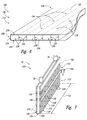
- Fig. 6 is a schematic fragmentary view of examples of a body 130 that may define vertically oriented vacuum surface 132 of vacuum chucks 100 according to the present disclosure.
- Body 130 also may be referred to herein as a panel 212 and/or as a double walled panel 212 and may be formed from any suitable material.
- body 130 may be formed from and/or may include a polymeric material and/or a polycarbonate.
- Body 130 includes a first planar wall 230, a second, opposed planar wall 232, and a plurality of elongate webs 234 that extend between first planar wall 230 and second planar wall 232.
- First planar wall 230 may define vertically oriented vacuum surface 132 of chucks 100, while second planar wall 232 may be operatively attached to elongate rigid support 120 of chucks 100.
- Planar walls 230 and 232, together with the plurality of elongate webs 234, define a plurality of elongate channels 236 that extend within body 130.
- channels 236 may extend along a longitudinal axis that is parallel to first planar wall 230 and/or second planar wall 232, may extend from an edge 238 of body 130, may extend from a first edge of body 130 to a second edge of body 130, and/or may extend between two opposed edges of body 130.
- First planar wall 230 also may define vacuum holes 134.
- Each vacuum hole 134 may be in fluid communication with one or more selected elongate channels 236, which may form a portion of vacuum manifold 160 of Fig. 5 .
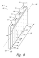
- Figs. 7-8 are less schematic profile views of vacuum chucks 100, according to the present disclosure, that may be included in and/or may form a portion of systems 20.
- chucks 100 include an elongate rigid support 120 and at least one body 130, in the form of a double walled panel 212, that is supported by and/or operatively attached to elongate rigid support 120.
- Body 130 defines a vertically oriented vacuum surface 132 that includes a plurality of vacuum holes 134.
- vertically oriented vacuum surface 132 extends along a length 122 of elongate rigid support 120.
- Chucks 100 of Figs. 7-8 also include a vacuum manifold 160 and one or more vacuum sources 76.
- vacuum sources 76 may be lightweight and/or modular vacuum sources that may be attached, or directly attached to chuck 100 and/or to vacuum manifold 160 thereof.
- each vacuum source 76 may be configured to independently apply the retention vacuum to a respective region 133 of vertically oriented vacuum surface 132, as discussed herein.
- Vacuum manifold 160 provides fluid communication between vacuum sources 76 and vacuum holes 134.
- Fig. 7 illustrates vacuum manifold 160 as being at least partially defined by elongate rigid support 120. Under these conditions, the ends of elongate channels 236 may be sealed and second planar wall 232 may include holes to permit fluid communication between elongate channels 236 and vacuum manifold 160.
- Fig. 8 illustrates vacuum manifold 160 as being at least partially defined by a vacuum conduit 164 that is external to elongate rigid support 120. Under these conditions, one end of elongate channels 236 may be sealed and vacuum conduit 164 may be in fluid communication with the other end of elongate channels 236.
- Chucks 100 of Figs. 7-8 further include a skirt seal 170 that extends along length 122 of elongate rigid support 120.
- chuck 100 of Fig. 7 includes an auxiliary retention mechanism 190, in the form of a retention strap, which may be selectively extended along the length of elongate rigid support 120.
- elongate channels 236 of double walled panel 212 may extend in any suitable direction and/or with any suitable orientation relative to elongate rigid support 120.
- elongate channels 236 may extend in a horizontal, or at least substantially horizontal, direction and/or may extend parallel, or at least substantially parallel, to a longitudinal axis 102 of chuck 100.
- elongate channels 236 may extend in a vertical, or at least substantially vertical, direction and/or may extend perpendicular, or at least substantially perpendicular, to longitudinal axis 102 of chuck 100.
- Figs. 9-13 are schematic cross-sectional views of vacuum chucks 100 according to the present disclosure and illustrate various relative configurations for elongate rigid supports 120 and bodies 130 that define vertically oriented vacuum surfaces 132.
- chucks 100 are illustrated as including an elongate rigid support 120 and a body 130 that is operatively attached to elongate rigid support 120 and that defines a vertically oriented vacuum surface 132.
- Chucks 100 also are illustrated as including a lift support 104 that is operatively attached to elongate rigid support 120 and is configured to permit chucks 100 to be suspended thereby.
- Elongate rigid support 120 is a tubular structure that also defines at least a portion of a vacuum manifold 160, which is configured to provide a retention vacuum to vertically oriented vacuum surface 132.
- elongate rigid support 120 includes an opening 126 that permits fluid communication between an internal volume 128, which is defined by elongate rigid support 120, and body 130.
- an end of body 130 may be operatively attached to elongate rigid support 120 and body 130 may be suspended from elongate rigid support such that vertically oriented vacuum surface 132 may not be directly supported by elongate rigid support 120.
- body 130 may be configured to permit limited deformation and/or flexing along a length thereof.
- body 130 is centered on elongate rigid support 120 and/or is located vertically below lift support 104.
- body 130 is located proximal an edge, or side, of elongate rigid support 120, is offset from a center of elongate rigid support 120, and/or is offset from lift support 104.
- a face, or side, 138 of body 130 additionally or alternatively may be operatively attached to a surface 124 that is defined by elongate rigid support 120.
- face 138 of body 130 is only partially supported by and/or attached to elongate rigid support 120, while in Fig. 13 , face 138 of body 130 is completely (or at least substantially completely) supported by and/or attached to elongate rigid support 120.
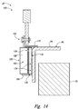
- Fig. 14 is a schematic cross-sectional view of a vacuum chuck 100, according to the present disclosure, retaining a flexible elongate body 90.
- a retention vacuum has been applied to a vacuum manifold 160, thereby retaining flexible elongate body 90 on a vertically oriented vacuum surface 132 of chuck 100 and permitting flexible elongate body 90 to be separated from a support surface 70 and/or transferred by chuck 100.
- a skirt seal 170 extends from chuck 100 and across an upper surface 94 of flexible elongate body 90 and restricts fluid flow therebetween.
- a lower seal 184 also extends into contact with flexible elongate body 90 and restricts fluid flow therebetween.
- FIGs. 15-17 are schematic side views of vacuum chucks 100, according to the present disclosure, that include vertically oriented vacuum surfaces 132 with a plurality of independent regions 133.
- Each region 133 may be associated with and/or in fluid communication with a respective independent vacuum manifold 160, and vacuum manifolds 160 may be configured to permit independent control of application of the retention vacuum to respective regions 133. This may include independent control of the presence and/or absence of the retention vacuum within a given region 133 and/or independent control of a level, or magnitude, of the retention vacuum that is applied to a given region 133.
- a flexible elongate body 90 that extends, at least substantially, along an entire length of chuck 100 may be retained on vertically oriented vacuum surface 132 through application of the retention vacuum to each region 133 of vertically oriented vacuum surface 132. This is illustrated by the dotted texture in each region 133 of vertically oriented vacuum surface 132.
- a portion of the plurality of regions 133 that retains flexible elongate body 90 may have the retention vacuum applied thereto, as illustrated by the dotted texture in the three leftmost regions 133 of fig. 16 .
- a portion of the plurality of regions 133 that does not retain flexible elongate body 90 may not have the retention vacuum applied thereto, as illustrated by the absence of the dotted texture in the three rightmost regions 133 of Fig. 16 .
- Such a configuration may decrease leakage of the retention vacuum and/or may decrease a power requirement of vacuum source 76.
- the plurality of regions 133 may be utilized to retain separate and/or distinct flexible elongate bodies 90 with chuck 100.
- one or more regions 133 may have a different level of retention vacuum applied thereto when compared to one or more other regions 133.
- each vacuum manifold 160 may have a separate and/or distinct vacuum source 76 associated therewith.
- a single vacuum source 76 may provide the retention vacuum to a plurality of vacuum manifolds 160, and one or more valves 166 may be utilized to control and/or regulate the application of the retention vacuum to a given vacuum manifold 160 and/or propagation of the retention vacuum between vacuum manifolds 160.
- Figs. 15-17 illustrate regions 133 of vertically oriented vacuum surface 132 as being spaced-apart horizontally and/or along a length of vertically oriented vacuum surface 132. However, this is not required in all embodiments. As an example, regions 133 additionally or alternatively may be spaced-apart vertically along a height of vertically oriented vacuum surface 132 (as illustrated in Fig. 7 ). In addition, Figs. 15-17 also illustrate regions 133 as being, at least substantially, the same size and/or as having, at least substantially, the same surface area. However, this is not required in all embodiments. As an example, a first region 133 may have a different length and/or a different surface area than a second region 133.
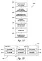
- Fig. 18 is a flowchart depicting methods 300, according to the present disclosure, of transferring a flexible elongate body.
- Methods 300 include suspending an elongate horizontal support structure at 310 and aligning a plurality of vacuum chucks at 320.
- Methods 300 further include selectively actuating the plurality of vacuum chucks at 330 and lifting the flexible elongate body at 340.
- Suspending the elongate horizontal support structure at 310 may include suspending with a transfer structure.
- the elongate horizontal support structure may form a portion of a system for transferring the flexible elongate body and may be operatively attached to an upper end of each of a plurality of vertical linkages.
- Each of the plurality of vertical linkages may extend vertically, or at least substantially vertically, from and/or below the elongate horizontal support structure.
- the system further may include a plurality of vacuum chucks, and a respective vacuum chuck may be operatively attached to a lower end of each of the plurality of vertical linkages.
- the suspending at 310 further may include suspending the plurality of vertical linkages via that elongate horizontal support structure and/or suspending the plurality of vacuum chucks via the plurality of vertical linkages.
- the suspending at 310 may be performed prior to the lifting at 340 and may include pre-deflecting the elongate horizontal support structure. This may decrease deflection and/or deformation of the elongate horizontal support structure during the lifting at 340 and/or may decrease deflection and/or deformation of the flexible elongate body subsequent to, during, and/or as a result of the lifting at 340.
- the suspending at 310 may be accomplished in any suitable manner.
- the suspending at 310 may include moving the elongate horizontal support structure in a vertical direction with the transfer structure. This may include moving such that a weight of the elongate horizontal support structure, a weight of the plurality of vertical linkages, and a weight of the plurality of vacuum chucks are supported by the transfer structure.
- Aligning the plurality of vacuum chucks at 320 may include aligning each of the plurality of vacuum chucks with a respective portion of a vertical surface of the flexible elongate body and may be accomplished in any suitable manner.
- the aligning at 320 may include rotating at least a portion of the plurality of vertical linkages relative to the elongate horizontal support structure. This may include rotating about a pivot axis that is perpendicular to a longitudinal axis of the elongate horizontal support structure and/or that is perpendicular to the vertical direction.
- the aligning at 320 may include rotating at least one of the plurality of vacuum chucks relative to a respective one of the plurality of vertical linkages.
- the aligning at 320 additionally or alternatively may include adjusting a length of at least one of the plurality of vertical linkages.
- the aligning at 320 may include aligning such that a longitudinal axis of each of the plurality of vacuum chucks is aligned with, or at least substantially aligned with, a trajectory of the respective portion of the vertical surface of the flexible elongate body. Additionally or alternatively, the aligning at 320 also may include aligning such that a longitudinal axis of a first portion of the plurality of vacuum chucks is not aligned with and/or is at a skew angle relative to a longitudinal axis of a second portion of the plurality of vacuum chucks.
- Selectively actuating the plurality of vacuum chucks at 330 may include selectively actuating each vacuum chuck to selectively retain the respective portion of the vertical surface of the flexible elongate body with the vacuum chuck.
- the selectively actuating at 330 may include selectively, operatively, and/or reversibly attaching each of the plurality of vacuum chucks to the respective portion of the vertical surface of the flexible elongate body.
- the selectively actuating at 330 may include applying a retention vacuum to an interface between each of the plurality of vacuum chucks and the respective portion of the vertical surface of the flexible elongate body.
- Lifting the flexible elongate body at 340 may include lifting via translation of the horizontal support structure. Additionally or alternatively, the lifting at 340 also may include lifting such that the flexible elongate body is suspended from the plurality of vacuum chucks, is supported by the plurality of vacuum chucks, and/or is fully supported by the plurality of vacuum chucks. The lifting at 340 may be accomplished in any suitable manner. As an example, the lifting at 340 may include translating the elongate horizontal support structure in the vertical direction, translating the elongate horizontal support structure with the transfer structure, and/or translating the elongate horizontal support structure such that a weight of the flexible elongate body is supported by the elongate horizontal support structure.
- exemplary method 900 may include specification and design 905 of the aircraft 700 and material procurement 910.
- component and subassembly manufacturing 915 and system integration 920 of the aircraft 700 take place.
- the aircraft 700 may go through certification and delivery 925 in order to be placed in service 930.
- routine maintenance and service 935 which also may include modification, reconfiguration, refurbishment, and so on).
- Each of the processes of method 900 may be performed or carried out by a system integrator, a third party, and/or an operator (e.g., a customer).
- a system integrator may include without limitation any number of aircraft manufacturers and major-system subcontractors
- a third party may include without limitation any number of venders, subcontractors, and suppliers
- an operator may be an airline, leasing company, military entity, service organization, and so on.
- aircraft 700 produced by exemplary method 900 may include an airframe 710 with a plurality of systems 712 and an interior 714.
- high-level systems 712 include one or more of a propulsion system 715, an electrical system 716, a hydraulic system 717, and an environmental system 718. Any number of other systems may be included.
- an aerospace example is shown, the principles of the invention may be applied to other industries, such as the automotive industry.
- Systems and methods embodied herein may be employed during any one or more of the stages of the manufacturing and service method 900.
- components or subassemblies corresponding to component and subassembly manufacturing process 915 may be fabricated or manufactured in a manner similar to components or subassemblies produced while the aircraft 700 is in service.
- one or more system embodiments, method embodiments, or a combination thereof may be utilized during the production stages 915 and 920, for example, by substantially expediting assembly of or reducing the cost of an aircraft 700.
- one or more of system embodiments, method embodiments, or a combination thereof may be utilized while the aircraft 700 is in service, for example and without limitation, to maintenance and service 935.
- the terms “adapted” and “configured” mean that the element, component, or other subject matter is designed and/or intended to perform a given function. Thus, the use of the terms “adapted” and “configured” should not be construed to mean that a given element, component, or other subject matter is simply “capable of” performing a given function but that the element, component, and/or other subject matter is specifically selected, created, implemented, utilized, programmed, and/or designed for the purpose of performing the function. It is also within the scope of the present disclosure that elements, components, and/or other recited subject matter that is recited as being adapted to perform a particular function may additionally or alternatively be described as being configured to perform that function, and vice versa. Similarly, subject matter that is recited as being configured to perform a particular function may additionally or alternatively be described as being operative to perform that function.
- the phrase, "for example,” the phrase, “as an example,” and/or simply the term “example,” when used with reference to one or more components, features, details, structures, embodiments, and/or methods according to the present disclosure, are intended to convey that the described component, feature, detail, structure, embodiment, and/or method is an illustrative, non-exclusive example of components, features, details, structures, embodiments, and/or methods according to the present disclosure.
Landscapes
- Engineering & Computer Science (AREA)
- Mechanical Engineering (AREA)
- Transportation (AREA)
- Manufacturing & Machinery (AREA)
- Aviation & Aerospace Engineering (AREA)
- Physics & Mathematics (AREA)
- Geometry (AREA)
- Manipulator (AREA)
- Container, Conveyance, Adherence, Positioning, Of Wafer (AREA)
- Lining Or Joining Of Plastics Or The Like (AREA)
- Blow-Moulding Or Thermoforming Of Plastics Or The Like (AREA)
Applications Claiming Priority (1)
| Application Number | Priority Date | Filing Date | Title |
|---|---|---|---|
| US14/633,979 US9663247B2 (en) | 2015-02-27 | 2015-02-27 | Systems, methods, and vacuum chucks for transferring flexible elongate bodies |
Publications (3)
| Publication Number | Publication Date |
|---|---|
| EP3061569A2 true EP3061569A2 (de) | 2016-08-31 |
| EP3061569A3 EP3061569A3 (de) | 2016-11-30 |
| EP3061569B1 EP3061569B1 (de) | 2018-10-10 |
Family
ID=55349729
Family Applications (1)
| Application Number | Title | Priority Date | Filing Date |
|---|---|---|---|
| EP16155112.2A Active EP3061569B1 (de) | 2015-02-27 | 2016-02-10 | Vakuumspannfutter zum transfer von flexiblen länglichen körpern |
Country Status (2)
| Country | Link |
|---|---|
| US (1) | US9663247B2 (de) |
| EP (1) | EP3061569B1 (de) |
Cited By (3)
| Publication number | Priority date | Publication date | Assignee | Title |
|---|---|---|---|---|
| EP4000899A1 (de) | 2020-11-18 | 2022-05-25 | The Boeing Company | Verfahren und system zum tragen von paneelen von flugzeugflügeln |
| NL2027392B1 (en) * | 2021-01-26 | 2022-08-12 | Boeing Co | Assembly line fabrication and assembly of aircraft wings |
| US11807395B2 (en) | 2020-11-18 | 2023-11-07 | The Boeing Company | Assembly line fabrication and assembly of aircraft wings |
Families Citing this family (13)
| Publication number | Priority date | Publication date | Assignee | Title |
|---|---|---|---|---|
| US10843449B2 (en) | 2017-12-14 | 2020-11-24 | The Boeing Company | Method and apparatus for forming composite plies on contoured tool surfaces |
| US11485519B2 (en) * | 2018-07-12 | 2022-11-01 | The Boeing Company | Wing panel assembly system and method |
| US12194693B2 (en) * | 2020-12-07 | 2025-01-14 | The Boeing Company | Forming apparatus, method, and system |
| US11826970B2 (en) | 2020-12-07 | 2023-11-28 | The Boeing Company | Forming apparatus, method, and system |
| US11964442B2 (en) | 2020-12-07 | 2024-04-23 | The Boeing Company | Forming apparatus, method, and system |
| US11654641B2 (en) | 2020-12-07 | 2023-05-23 | The Boeing Company | Composite ply placement system and method |
| US11685128B2 (en) | 2020-12-07 | 2023-06-27 | The Boeing Company | System and method for fabricating a composite structure |
| US12304062B2 (en) * | 2021-01-04 | 2025-05-20 | The Boeing Company | Part transfer system |
| US11897209B2 (en) | 2021-08-30 | 2024-02-13 | The Boeing Company | Composite forming apparatus, system and method |
| US11999116B2 (en) | 2021-08-30 | 2024-06-04 | The Boeing Company | Composite forming apparatus, system and method |
| US12103249B2 (en) | 2021-08-30 | 2024-10-01 | The Boeing Company | Composite forming apparatus, methods, and systems |
| US12138864B2 (en) | 2021-08-30 | 2024-11-12 | The Boeing Company | Forming apparatus, methods, and systems |
| DK202270528A1 (en) * | 2022-10-31 | 2024-06-14 | Alvac Ind A/S | A lifting apparatus and a method for lifting a longitudinal bendable structure such as a wind turbine blade. |
Family Cites Families (40)
| Publication number | Priority date | Publication date | Assignee | Title |
|---|---|---|---|---|
| FR895153A (fr) | 1943-06-01 | 1945-01-17 | Forges Ateliers Const Electr | Procédé de scellage des feuilles de verre sur les tables d'appareils à doucir ou à polir les glaces ou matières analogues et moyens de mise en oeuvre de ce procédé |
| US2893581A (en) * | 1957-10-31 | 1959-07-07 | Walton W Cushman | Suction lift means for industrial lift trucks |
| US2942745A (en) * | 1958-11-17 | 1960-06-28 | Yale & Towne Mfg Co | Vacuum lift device |
| US3054521A (en) * | 1958-12-22 | 1962-09-18 | Hyster Co | Apparatus for handling loads |
| US3118554A (en) * | 1959-03-23 | 1964-01-21 | Hyster Co | Vacuum handling apparatus |
| US3187989A (en) * | 1962-11-19 | 1965-06-08 | Yale & Towne Inc | Vacuum system |
| US4066249A (en) | 1977-05-11 | 1978-01-03 | Grumman Aerospace Corporation | Modular vacuum work area |
| US4129328A (en) * | 1977-06-20 | 1978-12-12 | Littell Edmund R | Plate handling apparatus with load deflection compensation |
| IT1176164B (it) | 1984-05-22 | 1987-08-18 | Bini & C Srl | Procedimento ed apparecchiatura per il sollevamento ed il trasporto di oggetti sistemati su supporti a vassoio o simili |
| DE3824155A1 (de) * | 1988-07-16 | 1990-01-25 | Focke & Co | Vorrichtung zum heben von tray-packungen |
| US5348602A (en) | 1993-06-08 | 1994-09-20 | General Electric Company | Method for making a bonded laminated article bend portion |
| DE19928734B4 (de) * | 1998-04-21 | 2007-08-23 | J. Schmalz Kg | Unterdruckhandhabungseinrichtung |
| US6245275B1 (en) | 1999-05-13 | 2001-06-12 | Vought Aircraft Industries, Inc. | Method for fabricating composite structures |
| US6431623B1 (en) * | 1999-06-11 | 2002-08-13 | Honeywell International Inc. | Vacuum device for peeling off thin sheets |
| DE10119029A1 (de) * | 2001-04-18 | 2002-10-24 | Fezer Maschf Albert | Vakuum-Spannvorrichtung |
| DE20112633U1 (de) * | 2001-07-31 | 2002-02-21 | Festo AG & Co, 73734 Esslingen | Handhabungsvorrichtung, insbesondere zur Handhabung von Platten und Folien |
| GB0201837D0 (en) * | 2002-01-26 | 2002-03-13 | Palamatic Handling Syst | "Vacuum lifting apparatus etc" |
| US7134649B2 (en) | 2004-05-27 | 2006-11-14 | The Boeing Company | Conformal vacuum cup apparatus and method |
| DE102006046624A1 (de) | 2006-09-29 | 2008-04-03 | Brötje-Automation GmbH | Verfahren und Transportvorrichtung zum Transportieren von Gegenständen |
| DE102007052012A1 (de) * | 2007-10-31 | 2009-05-07 | Grenzebach Maschinenbau Gmbh | Verfahren und Vorrichtung zum Erfassen und Umladen von Gepäckstücken |
| FR2928855B1 (fr) | 2008-03-21 | 2010-04-16 | Applic De Productivite Logisti | Dispositif a effet de ventouse pour le transport de charges |
| FR2930766B1 (fr) * | 2008-04-30 | 2010-05-07 | Coval | Appareil de prehension par aspiration |
| DE102008032574A1 (de) * | 2008-07-11 | 2010-01-14 | Brötje-Automation GmbH | Vorrichtung zur Verwendung bei der Herstellung faserverstärkter Bauteile |
| US8863939B2 (en) | 2009-12-14 | 2014-10-21 | Xerox Corporation | Surface roughness for improved vacuum pressure for efficient media hold-down performance |
| IT1401339B1 (it) | 2010-07-30 | 2013-07-18 | Piazza | Attrezzatura perfezionata per la movimentazione di prodotti lastriformi singoli o in pacco |
| DE102010034720B4 (de) * | 2010-08-18 | 2013-11-14 | Deutsches Zentrum für Luft- und Raumfahrt e.V. | Flächengreifer |
| US8534730B2 (en) * | 2010-08-18 | 2013-09-17 | Deutsches Zentrum Fur Luft- Und Raumfahrt E.V. (Dlr E.V.) | Areal gripper |
| US8944481B2 (en) * | 2010-12-31 | 2015-02-03 | Fundacion Tecnalia Research & Innovation | Gripping device for manipulating flexible elements |
| DE202011100042U1 (de) | 2011-04-29 | 2012-05-02 | Bystronic Armatec Gmbh | Handhabungsvorrichtung mit einer in vertikaler Richtung verfahrbaren Bedieneinheit für eine Glasplatte, insbesondere ein mehrlagiges Glaspaket |
| US8857877B2 (en) * | 2011-05-04 | 2014-10-14 | GM Global Technology Operations LLC | Reconfigurable end-effector attachable to a robotic arm |
| DE102011106214A1 (de) * | 2011-06-07 | 2012-12-13 | Brötje-Automation GmbH | Endeffektor |
| JP6173818B2 (ja) * | 2012-08-17 | 2017-08-02 | バット ホールディング アーゲー | バルブ |
| US8826957B2 (en) | 2012-08-31 | 2014-09-09 | General Electric Company | Methods and systems for automated ply layup for composites |
| FR2995244B1 (fr) | 2012-09-07 | 2014-10-10 | Airbus Operations Sas | Procede de realisation d'un profile en materiau composite presentant un angle rentrant a partir d'un empilage de couches de fibres |
| DE102012019841B4 (de) * | 2012-10-09 | 2022-01-05 | Grenzebach Maschinenbau Gmbh | Verfahren und Vorrichtung für das Umsetzen großflächiger Platten in extremer Übergröße |
| US8974618B1 (en) | 2012-12-04 | 2015-03-10 | The Boeing Company | Systems and methods for assembling a skin of a composite structure |
| US9314976B2 (en) | 2013-02-15 | 2016-04-19 | The Boeing Company | Systems and methods for compacting a charge of composite material |
| US9375908B2 (en) | 2013-05-03 | 2016-06-28 | The Boeing Company | Flexible material transfer devices, flexible vacuum compaction devices, flexible vacuum chucks, and systems and methods including the same |
| ITTO20131020A1 (it) | 2013-12-13 | 2015-06-14 | Alenia Aermacchi Spa | Attrezzo e procedimento per la formatura e l'assemblaggio di longheroni di materiale composito |
| CN104016218B (zh) | 2014-06-24 | 2016-04-13 | 山东温声玻璃有限公司 | 一种吊装玻璃的吸盘架 |
-
2015
- 2015-02-27 US US14/633,979 patent/US9663247B2/en active Active
-
2016
- 2016-02-10 EP EP16155112.2A patent/EP3061569B1/de active Active
Non-Patent Citations (1)
| Title |
|---|
| None |
Cited By (3)
| Publication number | Priority date | Publication date | Assignee | Title |
|---|---|---|---|---|
| EP4000899A1 (de) | 2020-11-18 | 2022-05-25 | The Boeing Company | Verfahren und system zum tragen von paneelen von flugzeugflügeln |
| US11807395B2 (en) | 2020-11-18 | 2023-11-07 | The Boeing Company | Assembly line fabrication and assembly of aircraft wings |
| NL2027392B1 (en) * | 2021-01-26 | 2022-08-12 | Boeing Co | Assembly line fabrication and assembly of aircraft wings |
Also Published As
| Publication number | Publication date |
|---|---|
| US20160251091A1 (en) | 2016-09-01 |
| EP3061569A3 (de) | 2016-11-30 |
| US9663247B2 (en) | 2017-05-30 |
| EP3061569B1 (de) | 2018-10-10 |
Similar Documents
| Publication | Publication Date | Title |
|---|---|---|
| US9663247B2 (en) | Systems, methods, and vacuum chucks for transferring flexible elongate bodies | |
| US20170021534A1 (en) | Systems and methods for incrementally forming a composite part | |
| US9144959B1 (en) | Methods for assembling a skin of a composite structure | |
| EP2998228B1 (de) | Verfahren und vorrichtung zur montage von versteiften verbundstrukturen | |
| US9511548B1 (en) | Systems and methods for assembling a skin of a composite structure | |
| US9314976B2 (en) | Systems and methods for compacting a charge of composite material | |
| US9375908B2 (en) | Flexible material transfer devices, flexible vacuum compaction devices, flexible vacuum chucks, and systems and methods including the same | |
| US9993980B2 (en) | Methods for forming radius fillers for composite structures | |
| US8974618B1 (en) | Systems and methods for assembling a skin of a composite structure | |
| JP6811035B2 (ja) | 補強された複合構造体を製造するためのシステム及び方法 | |
| US10688697B2 (en) | Apparatus and method of forming a composite structure | |
| US9993947B2 (en) | Fabrication of stiffened composite panels | |
| US20190193371A1 (en) | Stiffened stringer panel with integral indexing laminate stacks | |
| US10226915B1 (en) | Systems of forming a skin for a composite structure | |
| EP2977189A1 (de) | Umformpressen und verfahren zur herstellung von geschüttelten, versteiften verbundstrukturen | |
| EP2871048B1 (de) | Verfahren und Werkzeuge zur Herstellung profilierter Verbundstrukturen mit Formgedächtnislegierung | |
| US8906179B2 (en) | Systems, tools, and methods for forming composite tubular stringers and stiffened composite structures having composite tubular stringers | |
| EP3023233A1 (de) | Flexible Materialübertragungsvorrichtungen, flexible Vakuumverdichtungsvorrichtungen, flexible Vakuumspannvorrichtungen und Systeme und Verfahren damit | |
| EP3023234B1 (de) | Herstellung von versteiften Verbundplatten | |
| CN102615528A (zh) | 飞机大型薄壁件滚压机附属柔性自动托架装置 | |
| US11046032B2 (en) | Composite charge positioning system | |
| US9895848B2 (en) | Systems and tooling for manufacturing composite parts and related methods | |
| Monner et al. | Single Slotted Flap | |
| US10005234B2 (en) | Devices, systems, and methods for compacting a charge of composite material across an edge | |
| US12043005B2 (en) | Mandrel support system and method |
Legal Events
| Date | Code | Title | Description |
|---|---|---|---|
| PUAI | Public reference made under article 153(3) epc to a published international application that has entered the european phase |
Free format text: ORIGINAL CODE: 0009012 |
|
| 17P | Request for examination filed |
Effective date: 20160210 |
|
| AK | Designated contracting states |
Kind code of ref document: A2 Designated state(s): AL AT BE BG CH CY CZ DE DK EE ES FI FR GB GR HR HU IE IS IT LI LT LU LV MC MK MT NL NO PL PT RO RS SE SI SK SM TR |
|
| AX | Request for extension of the european patent |
Extension state: BA ME |
|
| PUAL | Search report despatched |
Free format text: ORIGINAL CODE: 0009013 |
|
| AK | Designated contracting states |
Kind code of ref document: A3 Designated state(s): AL AT BE BG CH CY CZ DE DK EE ES FI FR GB GR HR HU IE IS IT LI LT LU LV MC MK MT NL NO PL PT RO RS SE SI SK SM TR |
|
| AX | Request for extension of the european patent |
Extension state: BA ME |
|
| RIC1 | Information provided on ipc code assigned before grant |
Ipc: B23Q 3/08 20060101ALI20161025BHEP Ipc: B64F 5/00 20060101ALN20161025BHEP Ipc: B25B 11/00 20060101AFI20161025BHEP Ipc: B66C 1/02 20060101ALI20161025BHEP |
|
| GRAP | Despatch of communication of intention to grant a patent |
Free format text: ORIGINAL CODE: EPIDOSNIGR1 |
|
| STAA | Information on the status of an ep patent application or granted ep patent |
Free format text: STATUS: GRANT OF PATENT IS INTENDED |
|
| RIC1 | Information provided on ipc code assigned before grant |
Ipc: B64F 5/40 20170101ALI20180329BHEP Ipc: B64F 5/00 20170101ALN20180329BHEP Ipc: B66C 1/02 20060101ALI20180329BHEP Ipc: B64F 5/50 20170101ALI20180329BHEP Ipc: B23Q 3/08 20060101ALI20180329BHEP Ipc: B25B 11/00 20060101AFI20180329BHEP |
|
| INTG | Intention to grant announced |
Effective date: 20180423 |
|
| GRAS | Grant fee paid |
Free format text: ORIGINAL CODE: EPIDOSNIGR3 |
|
| GRAA | (expected) grant |
Free format text: ORIGINAL CODE: 0009210 |
|
| STAA | Information on the status of an ep patent application or granted ep patent |
Free format text: STATUS: THE PATENT HAS BEEN GRANTED |
|
| AK | Designated contracting states |
Kind code of ref document: B1 Designated state(s): AL AT BE BG CH CY CZ DE DK EE ES FI FR GB GR HR HU IE IS IT LI LT LU LV MC MK MT NL NO PL PT RO RS SE SI SK SM TR |
|
| REG | Reference to a national code |
Ref country code: GB Ref legal event code: FG4D |
|
| REG | Reference to a national code |
Ref country code: CH Ref legal event code: EP Ref country code: AT Ref legal event code: REF Ref document number: 1050667 Country of ref document: AT Kind code of ref document: T Effective date: 20181015 |
|
| REG | Reference to a national code |
Ref country code: IE Ref legal event code: FG4D |
|
| REG | Reference to a national code |
Ref country code: DE Ref legal event code: R096 Ref document number: 602016006290 Country of ref document: DE |
|
| REG | Reference to a national code |
Ref country code: NL Ref legal event code: MP Effective date: 20181010 |
|
| REG | Reference to a national code |
Ref country code: LT Ref legal event code: MG4D |
|
| REG | Reference to a national code |
Ref country code: AT Ref legal event code: MK05 Ref document number: 1050667 Country of ref document: AT Kind code of ref document: T Effective date: 20181010 |
|
| PG25 | Lapsed in a contracting state [announced via postgrant information from national office to epo] |
Ref country code: NL Free format text: LAPSE BECAUSE OF FAILURE TO SUBMIT A TRANSLATION OF THE DESCRIPTION OR TO PAY THE FEE WITHIN THE PRESCRIBED TIME-LIMIT Effective date: 20181010 |
|
| PG25 | Lapsed in a contracting state [announced via postgrant information from national office to epo] |
Ref country code: ES Free format text: LAPSE BECAUSE OF FAILURE TO SUBMIT A TRANSLATION OF THE DESCRIPTION OR TO PAY THE FEE WITHIN THE PRESCRIBED TIME-LIMIT Effective date: 20181010 Ref country code: AT Free format text: LAPSE BECAUSE OF FAILURE TO SUBMIT A TRANSLATION OF THE DESCRIPTION OR TO PAY THE FEE WITHIN THE PRESCRIBED TIME-LIMIT Effective date: 20181010 Ref country code: LT Free format text: LAPSE BECAUSE OF FAILURE TO SUBMIT A TRANSLATION OF THE DESCRIPTION OR TO PAY THE FEE WITHIN THE PRESCRIBED TIME-LIMIT Effective date: 20181010 Ref country code: NO Free format text: LAPSE BECAUSE OF FAILURE TO SUBMIT A TRANSLATION OF THE DESCRIPTION OR TO PAY THE FEE WITHIN THE PRESCRIBED TIME-LIMIT Effective date: 20190110 Ref country code: IS Free format text: LAPSE BECAUSE OF FAILURE TO SUBMIT A TRANSLATION OF THE DESCRIPTION OR TO PAY THE FEE WITHIN THE PRESCRIBED TIME-LIMIT Effective date: 20190210 Ref country code: FI Free format text: LAPSE BECAUSE OF FAILURE TO SUBMIT A TRANSLATION OF THE DESCRIPTION OR TO PAY THE FEE WITHIN THE PRESCRIBED TIME-LIMIT Effective date: 20181010 Ref country code: PL Free format text: LAPSE BECAUSE OF FAILURE TO SUBMIT A TRANSLATION OF THE DESCRIPTION OR TO PAY THE FEE WITHIN THE PRESCRIBED TIME-LIMIT Effective date: 20181010 Ref country code: HR Free format text: LAPSE BECAUSE OF FAILURE TO SUBMIT A TRANSLATION OF THE DESCRIPTION OR TO PAY THE FEE WITHIN THE PRESCRIBED TIME-LIMIT Effective date: 20181010 Ref country code: BG Free format text: LAPSE BECAUSE OF FAILURE TO SUBMIT A TRANSLATION OF THE DESCRIPTION OR TO PAY THE FEE WITHIN THE PRESCRIBED TIME-LIMIT Effective date: 20190110 Ref country code: LV Free format text: LAPSE BECAUSE OF FAILURE TO SUBMIT A TRANSLATION OF THE DESCRIPTION OR TO PAY THE FEE WITHIN THE PRESCRIBED TIME-LIMIT Effective date: 20181010 |
|
| PG25 | Lapsed in a contracting state [announced via postgrant information from national office to epo] |
Ref country code: RS Free format text: LAPSE BECAUSE OF FAILURE TO SUBMIT A TRANSLATION OF THE DESCRIPTION OR TO PAY THE FEE WITHIN THE PRESCRIBED TIME-LIMIT Effective date: 20181010 Ref country code: AL Free format text: LAPSE BECAUSE OF FAILURE TO SUBMIT A TRANSLATION OF THE DESCRIPTION OR TO PAY THE FEE WITHIN THE PRESCRIBED TIME-LIMIT Effective date: 20181010 Ref country code: SE Free format text: LAPSE BECAUSE OF FAILURE TO SUBMIT A TRANSLATION OF THE DESCRIPTION OR TO PAY THE FEE WITHIN THE PRESCRIBED TIME-LIMIT Effective date: 20181010 Ref country code: GR Free format text: LAPSE BECAUSE OF FAILURE TO SUBMIT A TRANSLATION OF THE DESCRIPTION OR TO PAY THE FEE WITHIN THE PRESCRIBED TIME-LIMIT Effective date: 20190111 Ref country code: PT Free format text: LAPSE BECAUSE OF FAILURE TO SUBMIT A TRANSLATION OF THE DESCRIPTION OR TO PAY THE FEE WITHIN THE PRESCRIBED TIME-LIMIT Effective date: 20190210 |
|
| REG | Reference to a national code |
Ref country code: DE Ref legal event code: R097 Ref document number: 602016006290 Country of ref document: DE |
|
| PG25 | Lapsed in a contracting state [announced via postgrant information from national office to epo] |
Ref country code: DK Free format text: LAPSE BECAUSE OF FAILURE TO SUBMIT A TRANSLATION OF THE DESCRIPTION OR TO PAY THE FEE WITHIN THE PRESCRIBED TIME-LIMIT Effective date: 20181010 Ref country code: IT Free format text: LAPSE BECAUSE OF FAILURE TO SUBMIT A TRANSLATION OF THE DESCRIPTION OR TO PAY THE FEE WITHIN THE PRESCRIBED TIME-LIMIT Effective date: 20181010 Ref country code: CZ Free format text: LAPSE BECAUSE OF FAILURE TO SUBMIT A TRANSLATION OF THE DESCRIPTION OR TO PAY THE FEE WITHIN THE PRESCRIBED TIME-LIMIT Effective date: 20181010 |
|
| PLBE | No opposition filed within time limit |
Free format text: ORIGINAL CODE: 0009261 |
|
| STAA | Information on the status of an ep patent application or granted ep patent |
Free format text: STATUS: NO OPPOSITION FILED WITHIN TIME LIMIT |
|
| PG25 | Lapsed in a contracting state [announced via postgrant information from national office to epo] |
Ref country code: SK Free format text: LAPSE BECAUSE OF FAILURE TO SUBMIT A TRANSLATION OF THE DESCRIPTION OR TO PAY THE FEE WITHIN THE PRESCRIBED TIME-LIMIT Effective date: 20181010 Ref country code: EE Free format text: LAPSE BECAUSE OF FAILURE TO SUBMIT A TRANSLATION OF THE DESCRIPTION OR TO PAY THE FEE WITHIN THE PRESCRIBED TIME-LIMIT Effective date: 20181010 Ref country code: SM Free format text: LAPSE BECAUSE OF FAILURE TO SUBMIT A TRANSLATION OF THE DESCRIPTION OR TO PAY THE FEE WITHIN THE PRESCRIBED TIME-LIMIT Effective date: 20181010 Ref country code: RO Free format text: LAPSE BECAUSE OF FAILURE TO SUBMIT A TRANSLATION OF THE DESCRIPTION OR TO PAY THE FEE WITHIN THE PRESCRIBED TIME-LIMIT Effective date: 20181010 |
|
| 26N | No opposition filed |
Effective date: 20190711 |
|
| REG | Reference to a national code |
Ref country code: CH Ref legal event code: PL |
|
| PG25 | Lapsed in a contracting state [announced via postgrant information from national office to epo] |
Ref country code: LU Free format text: LAPSE BECAUSE OF NON-PAYMENT OF DUE FEES Effective date: 20190210 Ref country code: SI Free format text: LAPSE BECAUSE OF FAILURE TO SUBMIT A TRANSLATION OF THE DESCRIPTION OR TO PAY THE FEE WITHIN THE PRESCRIBED TIME-LIMIT Effective date: 20181010 Ref country code: MC Free format text: LAPSE BECAUSE OF FAILURE TO SUBMIT A TRANSLATION OF THE DESCRIPTION OR TO PAY THE FEE WITHIN THE PRESCRIBED TIME-LIMIT Effective date: 20181010 |
|
| REG | Reference to a national code |
Ref country code: BE Ref legal event code: MM Effective date: 20190228 |
|
| REG | Reference to a national code |
Ref country code: IE Ref legal event code: MM4A |
|
| PG25 | Lapsed in a contracting state [announced via postgrant information from national office to epo] |
Ref country code: LI Free format text: LAPSE BECAUSE OF NON-PAYMENT OF DUE FEES Effective date: 20190228 Ref country code: CH Free format text: LAPSE BECAUSE OF NON-PAYMENT OF DUE FEES Effective date: 20190228 |
|
| REG | Reference to a national code |
Ref country code: DE Ref legal event code: R082 Ref document number: 602016006290 Country of ref document: DE Representative=s name: MAIER, LL.M., MICHAEL C., DE Ref country code: DE Ref legal event code: R082 Ref document number: 602016006290 Country of ref document: DE Representative=s name: BOULT WADE TENNANT LLP, DE |
|
| PG25 | Lapsed in a contracting state [announced via postgrant information from national office to epo] |
Ref country code: IE Free format text: LAPSE BECAUSE OF NON-PAYMENT OF DUE FEES Effective date: 20190210 |
|
| REG | Reference to a national code |
Ref country code: DE Ref legal event code: R082 Ref document number: 602016006290 Country of ref document: DE Representative=s name: BOULT WADE TENNANT LLP, DE |
|
| PG25 | Lapsed in a contracting state [announced via postgrant information from national office to epo] |
Ref country code: BE Free format text: LAPSE BECAUSE OF NON-PAYMENT OF DUE FEES Effective date: 20190228 |
|
| PG25 | Lapsed in a contracting state [announced via postgrant information from national office to epo] |
Ref country code: TR Free format text: LAPSE BECAUSE OF FAILURE TO SUBMIT A TRANSLATION OF THE DESCRIPTION OR TO PAY THE FEE WITHIN THE PRESCRIBED TIME-LIMIT Effective date: 20181010 |
|
| PG25 | Lapsed in a contracting state [announced via postgrant information from national office to epo] |
Ref country code: MT Free format text: LAPSE BECAUSE OF NON-PAYMENT OF DUE FEES Effective date: 20190210 |
|
| PG25 | Lapsed in a contracting state [announced via postgrant information from national office to epo] |
Ref country code: CY Free format text: LAPSE BECAUSE OF FAILURE TO SUBMIT A TRANSLATION OF THE DESCRIPTION OR TO PAY THE FEE WITHIN THE PRESCRIBED TIME-LIMIT Effective date: 20181010 |
|
| PG25 | Lapsed in a contracting state [announced via postgrant information from national office to epo] |
Ref country code: HU Free format text: LAPSE BECAUSE OF FAILURE TO SUBMIT A TRANSLATION OF THE DESCRIPTION OR TO PAY THE FEE WITHIN THE PRESCRIBED TIME-LIMIT; INVALID AB INITIO Effective date: 20160210 |
|
| PG25 | Lapsed in a contracting state [announced via postgrant information from national office to epo] |
Ref country code: MK Free format text: LAPSE BECAUSE OF FAILURE TO SUBMIT A TRANSLATION OF THE DESCRIPTION OR TO PAY THE FEE WITHIN THE PRESCRIBED TIME-LIMIT Effective date: 20181010 |
|
| P01 | Opt-out of the competence of the unified patent court (upc) registered |
Effective date: 20230516 |
|
| PGFP | Annual fee paid to national office [announced via postgrant information from national office to epo] |
Ref country code: GB Payment date: 20260227 Year of fee payment: 11 |
|
| PGFP | Annual fee paid to national office [announced via postgrant information from national office to epo] |
Ref country code: DE Payment date: 20260227 Year of fee payment: 11 |
|
| PGFP | Annual fee paid to national office [announced via postgrant information from national office to epo] |
Ref country code: FR Payment date: 20260225 Year of fee payment: 11 |