EP3060352B1 - Procédé de clarification d'un produit fluide au moyen d'une centrifugeuse - Google Patents
Procédé de clarification d'un produit fluide au moyen d'une centrifugeuse Download PDFInfo
- Publication number
- EP3060352B1 EP3060352B1 EP14792429.4A EP14792429A EP3060352B1 EP 3060352 B1 EP3060352 B1 EP 3060352B1 EP 14792429 A EP14792429 A EP 14792429A EP 3060352 B1 EP3060352 B1 EP 3060352B1
- Authority
- EP
- European Patent Office
- Prior art keywords
- product
- time interval
- parameter
- turbidity
- discharge
- Prior art date
- Legal status (The legal status is an assumption and is not a legal conclusion. Google has not performed a legal analysis and makes no representation as to the accuracy of the status listed.)
- Active
Links
- 238000000034 method Methods 0.000 title claims description 43
- 230000009969 flowable effect Effects 0.000 title claims description 4
- 239000007787 solid Substances 0.000 claims description 62
- 239000012071 phase Substances 0.000 claims description 43
- 238000005259 measurement Methods 0.000 claims description 29
- 238000011156 evaluation Methods 0.000 claims description 11
- 239000007788 liquid Substances 0.000 claims description 7
- 239000007791 liquid phase Substances 0.000 claims description 5
- 239000007790 solid phase Substances 0.000 claims description 3
- 238000007599 discharging Methods 0.000 claims 2
- 230000000977 initiatory effect Effects 0.000 claims 2
- 230000008859 change Effects 0.000 description 7
- 239000012530 fluid Substances 0.000 description 6
- 238000005352 clarification Methods 0.000 description 5
- 230000008569 process Effects 0.000 description 5
- 230000001960 triggered effect Effects 0.000 description 5
- 239000000126 substance Substances 0.000 description 4
- 238000001514 detection method Methods 0.000 description 3
- 230000007246 mechanism Effects 0.000 description 3
- 235000013361 beverage Nutrition 0.000 description 2
- 230000005540 biological transmission Effects 0.000 description 2
- 238000009795 derivation Methods 0.000 description 2
- 238000000691 measurement method Methods 0.000 description 2
- 229930014626 natural product Natural products 0.000 description 2
- 239000013049 sediment Substances 0.000 description 2
- XLYOFNOQVPJJNP-UHFFFAOYSA-N water Substances O XLYOFNOQVPJJNP-UHFFFAOYSA-N 0.000 description 2
- FGUUSXIOTUKUDN-IBGZPJMESA-N C1(=CC=CC=C1)N1C2=C(NC([C@H](C1)NC=1OC(=NN=1)C1=CC=CC=C1)=O)C=CC=C2 Chemical compound C1(=CC=CC=C1)N1C2=C(NC([C@H](C1)NC=1OC(=NN=1)C1=CC=CC=C1)=O)C=CC=C2 FGUUSXIOTUKUDN-IBGZPJMESA-N 0.000 description 1
- 235000013405 beer Nutrition 0.000 description 1
- 230000008901 benefit Effects 0.000 description 1
- 230000033228 biological regulation Effects 0.000 description 1
- 230000015572 biosynthetic process Effects 0.000 description 1
- 230000001276 controlling effect Effects 0.000 description 1
- 230000001419 dependent effect Effects 0.000 description 1
- 230000004069 differentiation Effects 0.000 description 1
- 230000000694 effects Effects 0.000 description 1
- 235000015203 fruit juice Nutrition 0.000 description 1
- 230000006872 improvement Effects 0.000 description 1
- 230000001151 other effect Effects 0.000 description 1
- 230000000704 physical effect Effects 0.000 description 1
- 230000001105 regulatory effect Effects 0.000 description 1
- 239000012266 salt solution Substances 0.000 description 1
- 238000002834 transmittance Methods 0.000 description 1
- 238000002604 ultrasonography Methods 0.000 description 1
- 235000015192 vegetable juice Nutrition 0.000 description 1
Images


Classifications
-
- B—PERFORMING OPERATIONS; TRANSPORTING
- B04—CENTRIFUGAL APPARATUS OR MACHINES FOR CARRYING-OUT PHYSICAL OR CHEMICAL PROCESSES
- B04B—CENTRIFUGES
- B04B1/00—Centrifuges with rotary bowls provided with solid jackets for separating predominantly liquid mixtures with or without solid particles
- B04B1/10—Centrifuges with rotary bowls provided with solid jackets for separating predominantly liquid mixtures with or without solid particles with discharging outlets in the plane of the maximum diameter of the bowl
- B04B1/14—Centrifuges with rotary bowls provided with solid jackets for separating predominantly liquid mixtures with or without solid particles with discharging outlets in the plane of the maximum diameter of the bowl with periodical discharge
-
- B—PERFORMING OPERATIONS; TRANSPORTING
- B04—CENTRIFUGAL APPARATUS OR MACHINES FOR CARRYING-OUT PHYSICAL OR CHEMICAL PROCESSES
- B04B—CENTRIFUGES
- B04B11/00—Feeding, charging, or discharging bowls
- B04B11/04—Periodical feeding or discharging; Control arrangements therefor
Definitions
- the invention relates to a method according to the preamble of claim 1.
- a product parameter - here the degree of turbidity of a clear phase running out of the drum - is determined and used to monitor the emptying of the solids space of the drum.
- the solid phase is emptied continuously. If the turbidity or the degree of turbidity becomes too high in the clear phase, the clear phase is returned to the drum.
- the object of the invention is to reduce this problem.
- the invention solves this problem by a method having the features of claim 1.
- step a the start time or the start of the product feed into the drum. Otherwise the time of the last emptying of solids is preferably used.
- the calibration period can also be determined indirectly from the time the solids are emptied or as a period between two solids empties. The further solids emptying of step d. In this respect, only the consequence of the deviation of the product parameter from the target value and the time of this event is dependent. Falling below a limit value can in particular be done according to the measurement method of WO 2008/058340 A1 be a suitable method in which the turbidity is measured in a separate line to the outlet of the drum and / or in a bypass line or the like.
- the actual value of the product parameter can be determined, for example, by a quasi-continuous determination of measured values. However, it is also possible to determine only a few measured values at slightly larger intervals. In this way, a measurement curve can be determined from the measured values, which allows a statement about the change in the product parameter.
- the triggering of the second solids discharge preferably ends the calibration interval.
- the clear phase carried out in the calibration interval corresponds qualitatively to the clear phase according to the prior art, since a change in the parameter has already started in a significant manner. Therefore, during the calibration interval no qualitative change compared to the prior art has been achieved. However, this improvement is made possible by the fact that steps e) and f) can now be used to set different times than is possible solely on the basis of the measurements, which is explained in more detail below using examples.
- Different mathematical operations can be used to determine and set the operating time interval. In this way, a preset time interval can be subtracted from the determined calibration time interval.
- the analysis curve or the end user can also analyze the measurement curve, that is to say the time course of the measurement values, over the calibration time interval, and the operating time interval can be set as a function of this evaluation.
- the solids can be emptied if the change is not yet measurable or only just measurable.
- the product parameter is, for example, the turbidity content of a clear phase
- an increase in the turbidity or the degree of turbidity in the clear phase is tolerated to a limit value.
- Some other emptying operations are then carried out in a time-controlled manner in such a way that this limit value is not reached in the first place and preferably even remains significantly below. In this way, the turbidity content of the overall derived clear phase is reduced and the overall quality of the derived clear phase is improved.
- the aforementioned steps of the method serve to control the operation of a separator.
- the individual process steps do not necessarily have to be carried out in one unit of the separator, but can alternatively be carried out by external devices (measuring devices, sensors, evaluation unit).
- the inlet volume flow or a product parameter of the starting product fed to the separator can be determined and steps a) - f) run through again if the volume flow changes or the product parameter changes beyond a limit value.
- the product parameter of the clear phase can be not only the degree of turbidity but also another measurable parameter - the viscosity and / or the conductivity. Sensors or measuring devices with appropriately designed sensors for determining these parameters can be attached to the separator at the corresponding processes in a comparatively simple manner.
- the operating time interval is selected such that within the operating time interval the product parameters of the clear phase immediately before emptying deviates by less than 50%, preferably less than 20%, from the product parameters of the clear phase immediately after the solids discharge. If, for example, you select the degree of turbidity as a parameter, you have been able to do so - among other things Fig. 2 results - only a solids discharge or a solids emptying take place if the degree of turbidity of the clear phase towards the end of the time interval in which the solids collected in the separator had reached a multiple of the degree of turbidity of the clear phase immediately after emptying. This excessive increase in the degree of turbidity in the clear phase shortly before emptying is prevented by the novel setting of the operating interval.
- the operating time interval is at least 5%, preferably at least 10%, shorter than the calibration time interval.
- the solids discharge takes place, as is customary in the case of a discontinuous solids discharge, preferably through discharge openings in the manner of nozzles, which can be closed and opened by a piston slide.
- This has the particular advantage that the opening state of the discharge nozzles can be precisely controlled.
- the calibration time interval and the operating interval and the setting of the operating time interval are preferably determined by means of an evaluation unit designed as a software routine of a control computer, which is connected to the sensors and which enables the actuation mechanism of the piston slide in the drum to be activated.
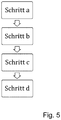
- a method for clarifying a flowable starting product (AP) with a centrifuge in particular a separator with a rotatable drum with an inlet and at least one liquid discharge for the continuous discharge of at least one clarified liquid phase - a clear phase - and with discontinuously opening solid discharge openings for discontinuous Discharge of the solid phase, which has at least the following steps: a) setting or determining a start time; b) repeated determination / measurement of at least one actual value of a product parameter of the clear phase (KP) derived from the drum; c) determining and evaluating the difference quotient from the determined product parameters and the respective time intervals between the measurements; and d) triggering a solids discharge as a result of the evaluation in step c).
- steps a) to d) preferably start again.
- the difference quotient is then determined and evaluated from the measured values of the product parameter and the time intervals between the measurements. Depending on this evaluation, emptying may be triggered. Only when the behavior of this difference quotient (i.e. the course of the numerical differentiation of the product parameter function, which is only approximately known in the form of discrete measured values, depending on the time) deviates from a predetermined and pre-stored behavior, in particular if the difference quotient (or the first derivative), for example The emptying is triggered once or several times, or falls below or exceeds a predetermined limit value.
- steps e) and f) are then carried out, i.e. one or a few further emptying intervals are fixed in time.
- the degree of turbidity is determined at intervals by a measurement.
- the difference quotients from the degree of turbidity and the time intervals between the respective measurements are then determined and evaluated.
- a (numerical) detection of a change, for example an increase, in the difference quotient enables a statement to be made, or advantageously a detection, at a relatively early point in time an onset of a clearer or faster increase in turbidity. In this situation, an additional emptying of solids makes sense. This procedure can also be used to prevent the risk of late emptying.
- Fig. 1 shows a separator 1 for clarifying turbidity-containing, flowable starting products AP with a drum with a vertical axis of rotation.
- the product is processed in continuous operation. This means that the product is fed in continuously and at least one cleared liquid phase, called the clear phase, is drained off.
- the separator has a discontinuous discharge of solids, the solid F separated from a starting product by clarification being removed at intervals by opening and reclosing discharge nozzles or discharge openings 5.
- the drum has a lower drum part 10 and a drum cover 11. It is also preferably surrounded by a hood 12.
- the drum is also on a drive spindle 2 is placed, which is rotatably mounted and can be driven by a motor.
- the drum has a product inlet 4, through which a starting product AP is passed into the drum. It also has at least one outlet 13 with a gripper, which is used to derive a clear phase KP from the drum.
- the gripper is a kind of centripetal pump.
- the liquid discharge could also be done by other means. In addition to clarification, it would also be conceivable to separate the product into two liquid phases of different densities. This would require a further liquid drain.
- the rotatable drum with a vertical axis of rotation preferably has a plate pack 14 made of axially spaced separating plates.
- a solid collecting space 8 is formed between the outer periphery of the plate pack 14 and the inner periphery of the drum in the region of its largest inner diameter. Solids, which are separated from the clear phase in the area of the plate pack 14, collect in the solids collecting space 8, from which the solids can be discharged from the drum via the discharge nozzles 5.
- the discharge nozzles 5 can be opened and closed by means of a piston slide 6, which is arranged in the lower drum part 11. When the discharge nozzles are open, the solid F is passed out of the drum into a solid trap 7.
- the drum has an actuating mechanism for moving the piston valve.
- it comprises at least one supply line 15 for a control fluid such as water and a valve arrangement 16 in the drum and further elements outside the drum.
- a control fluid such as water
- the supply of the control fluid is made possible via a control valve 17 arranged outside the drum, which is arranged in a supply line 19 for the control fluid arranged outside the drum, so that the control fluid can be sprayed into the drum for emptying by releasing the control valve or conversely, the inflow of control fluid can be stopped to move the spool accordingly to expose the discharge openings.
- the actuation mechanism here that Control valve 17 is connected via a data line 18 to a control unit 9 for controlling and / or regulating the solids discharge.
- At least one sensor 22 which is designed to determine one or more product parameters of the at least one clear phase, is arranged on or in the process 13 of the clear phase.
- Product parameters in the context of the present invention are, in particular, physical properties of the measurement medium “clear phase” such as the degree of turbidity, the viscosity or also the conductivity (for example in the case of salt solutions).
- the at least one sensor 22 can be designed as a photocell for determining the light transmittance.
- a sensor 3 for determining the flow rate or one or more product parameters of the starting product to be conducted into the drum is preferably also arranged on or in the inlet 4 for the starting product AP into the drum.
- These product parameters can also be physical parameters such as the turbidity or the viscosity of the starting product.
- Such measurement methods can also be carried out using sensors as transmission measurements or scattered light measurements.
- Another option for determining the degree of turbidity is ultrasound measurements.
- process parameters such as volume flow or flow rate are also known.
- the sensor can in each case be integrated into a measuring device which has a product parameter e.g. determines the degree of turbidity or conductivity and at the same time a process parameter - such as determines the flow rate of the clear phase.
- a turbidity measurement and / or a viscosity measurement of the starting product AP can be carried out on the product inlet 4 analogously to the determination of the product parameters of the clear phase KP.
- the sensors 3 and 22 are connected via data lines 20, 21 to the evaluation and control unit 9 (preferably a control computer of the separator), which evaluates the measured values determined and controls the movement of the piston slide 6 and thus also the time interval until the discharge nozzles 5 open .
- the evaluation and control unit 9 preferably a control computer of the separator
- the starting product AP is preferably fed continuously into the separator, where it is clarified. There is a continuous clear phase discharge of the clear phase KP.
- a limit value for the turbidity value which should not be exceeded was preset and the solids F were emptied out of the solids collecting space 6 when the determined turbidity value exceeded the limit value.
- the time interval from the last emptying of the solid space 6 of the separator 1 to the reaching of a predetermined first turbidity limit value is first determined, as has been the case up to now.
- This process step is as follows referred to as determining a calibration time interval.
- the calibration time interval is defined as the time between the last time the solid space of the separator was emptied until the first turbidity limit value was reached. As soon as the measured turbidity content has reached the first limit value, the solid space 6 is emptied.
- the emptying of the solid space during this process step is controlled by the measurement and the reaching of the desired value.
- an operating time interval is set.
- the operating time interval can be determined by subtracting a predetermined time interval from the calibration time interval. After passing through the specific operating time interval, the solids are emptied in a time-controlled manner. This virtually precedes an increase in the degree of turbidity and ensures that the quality of the clear phase is almost consistently good. A measurement of the turbidity content during this process step is not absolutely necessary, but is conceivable in order to intervene if the limit value is reached prematurely contrary to expectations.
- n can preferably vary between 5-50, particularly preferably between 8-30, runs. It is therefore recommended that the calibration time interval be determined again and the operating time interval set again after running the operating time intervals n times.
- the degree of turbidity of the clear phase also depends, among other things, on the degree of turbidity of the starting product, it is advisable to monitor the conditions at the inlet of the starting product.
- the flow current can be detected in this way.
- Fig. 2 represents the time course of the degree of turbidity T of the clear phase, provided the previous method is used.
- the turbidity or the degree of turbidity T is constant at one percent over the course of the 1st minute to the 9th minute. From the 9th minute, the degree of turbidity increases relatively quickly. In the 11th minute the setpoint of 5% turbidity is reached and the solids are emptied. As a result, the degree of turbidity drops again to 1%.
- the time window t (K) represents the calibration time interval.
- the time interval can be set manually or determined mathematically or depending on measured values in a database.
- the operating time interval t (b) can be determined by multiplying the calibration time interval by a factor less than 1.
- the time window t (B) represents the operating time interval. It can be seen that the turbidity in this time window is approximately constant at 1%.
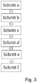
- step f) The sequence of steps a) to f) of claim 1 additionally illustrates Fig. 3 .
- step f) the method can start again at step a) and run through it again.
- An exemplary procedure shows Fig. 4 using the example of the product parameter "degree of turbidity" as a function of time.
- the detection of a change, for example an increase, in the difference quotient makes it possible to detect an onset of a faster increase in the turbidity at a relatively early point in time. In this situation, an additional emptying of solids makes sense. This procedure can also be used to prevent the risk of late emptying.
Landscapes
- Centrifugal Separators (AREA)
Claims (10)
- Procédé pour clarifier un produit de départ fluide (AP) avec une centrifugeuse, en particulier un séparateur, muni d'un tambour rotatif avec une arrivée et au moins une sortie de liquide pour la sortie en continu d'au moins une phase liquide clarifiée (phase clarifiée) et avec des ouvertures d'évacuation de solides à ouverture discontinue pour la sortie discontinue de la phase solide, caractérisé en ce qu'il comprend les étapes suivantes :a. réglage ou détermination du moment d'un démarrage ;b. détermination répétée d'au moins une valeur réelle d'un paramètre de produit de la phase clarifiée (KP) évacuée du tambour, lequel paramètre de produit de la phase clarifiée (KP) est la turbidité, la viscosité et/ou la conductivité ;c. détermination de l'intervalle d'étalonnage t/(K) entre le moment du démarrage et le moment où la valeur réelle du paramètre de produit ou un quotient de différence des valeurs réelles du paramètre de produit et des intervalles de temps entre les mesures atteint ou dépasse une valeur limite, en particulier une valeur limite du paramètre de produit ;d. déclenchement d'une sortie de solides quand la valeur limite, en particulier la valeur limite du paramètre de produit, est atteinte ou dépassée ;e. détermination et réglage d'un intervalle de temps de fonctionnement t(B) au moyen de l'intervalle de temps d'étalonnage t(K), l'intervalle de temps de fonctionnement t(B) étant inférieur d'au moins 5 % à l'intervalle de temps d'étalonnage t(K), etf. déclenchement d'au moins une ou plusieurs sorties de solides après l'écoulement de chaque intervalle de temps de fonctionnement t(B) réglé.
- Procédé selon la revendication 1, caractérisé en ce que le moment d'une première sortie de solides est déterminé dans l'étape a.
- Procédé selon la revendication 1 ou 2, caractérisé en ce qu'après un nombre prédéterminé (n) d'intervalles de temps de fonctionnement t(B), les étapes a à f sont à nouveau exécutées.
- Procédé selon la revendication 1, 2 ou 3, caractérisé en ce qu'une détermination du débit volumique ou d'un paramètre de produit du produit de départ (AP) amené au séparateur (1) est effectuée et les étapes a à f sont de nouveau exécutées si le débit volumique change ou si le paramètre de produit change jusqu'à une valeur limite ou au-delà d'une valeur limite.
- Procédé selon l'une des revendications précédentes, caractérisé en ce que l'intervalle de temps de fonctionnement t(B) est réglé de telle manière que dans l'intervalle de temps de fonctionnement t(B), le paramètre de produit immédiatement avant la vidange s'écarte de moins de 50 %, de préférence de moins de 20 %, du paramètre de produit immédiatement après la sortie de solides.
- Procédé selon l'une des revendications précédentes, caractérisé en ce que l'intervalle de temps de fonctionnement t(B) est inférieur d'au moins 10 % à l'intervalle de temps d'étalonnage.
- Procédé selon l'une des revendications précédentes, caractérisé en ce que la sortie de solides est effectuée à l'aide de buses de sortie (5), lesquelles buses de sortie (5) sont ouvertes et fermées par une vanne à piston (6).
- Procédé selon l'une des revendications précédentes, caractérisé en ce que la détermination du paramètre de produit de la phase clarifiée (KP) est effectuée par un capteur (22) qui est disposé dans ou sur un écoulement (13) du séparateur (1).
- Procédé selon l'une des revendications précédentes, caractérisé en ce que la détermination du paramètre de produit du produit de départ (AP) est effectuée par un capteur (3) qui est disposé dans ou sur une arrivée (4) du séparateur (1).
- Procédé selon l'une des revendications précédentes, caractérisé en ce que la détermination de l'intervalle de temps d'étalonnage t(K) et de l'intervalle de temps de fonctionnement t(B) et le réglage de l'intervalle de temps de fonctionnement t(B) sont effectués au moyen d'une unité d'analyse (9) qui est reliée aux capteurs (3, 22) et qui permet un réglage hydraulique de la position de la vanne à piston (6) dans le tambour.
Applications Claiming Priority (2)
| Application Number | Priority Date | Filing Date | Title |
|---|---|---|---|
| DE201310111576 DE102013111576A1 (de) | 2013-10-21 | 2013-10-21 | Verfahren zur Klärung eines fließfähigen Produktes mit einer Zentrifuge, insbesondere einem Separator |
| PCT/EP2014/072437 WO2015059091A1 (fr) | 2013-10-21 | 2014-10-20 | Procédé de clarification d'un produit fluide au moyen d'une centrifugeuse |
Publications (2)
| Publication Number | Publication Date |
|---|---|
| EP3060352A1 EP3060352A1 (fr) | 2016-08-31 |
| EP3060352B1 true EP3060352B1 (fr) | 2020-04-29 |
Family
ID=51844687
Family Applications (1)
| Application Number | Title | Priority Date | Filing Date |
|---|---|---|---|
| EP14792429.4A Active EP3060352B1 (fr) | 2013-10-21 | 2014-10-20 | Procédé de clarification d'un produit fluide au moyen d'une centrifugeuse |
Country Status (8)
| Country | Link |
|---|---|
| US (1) | US10040076B2 (fr) |
| EP (1) | EP3060352B1 (fr) |
| CN (1) | CN105658338A (fr) |
| AU (1) | AU2014339090B2 (fr) |
| DE (1) | DE102013111576A1 (fr) |
| NZ (1) | NZ719985A (fr) |
| RU (1) | RU2672412C2 (fr) |
| WO (1) | WO2015059091A1 (fr) |
Families Citing this family (6)
| Publication number | Priority date | Publication date | Assignee | Title |
|---|---|---|---|---|
| CN104849323B (zh) * | 2015-05-06 | 2017-06-30 | 浙江大学 | 一种基于电子鼻快速检测果汁中澄清剂的方法 |
| DE102015119165B4 (de) * | 2015-11-06 | 2022-06-09 | Gea Mechanical Equipment Gmbh | Verfahren zur Klärung eines fließfähigen Produktes mit einer Zentrifuge, insbesondere einem Separator |
| DE102017106801B3 (de) * | 2017-03-29 | 2018-08-02 | Gea Mechanical Equipment Gmbh | Selbstentleerender Separator zum schonenden Austrag von scherempfindlichen Produkten sowie Verfahren zu seinem Betrieb |
| DE102017111672B4 (de) * | 2017-03-29 | 2019-05-16 | Gea Mechanical Equipment Gmbh | Verfahren zur automatisierten Feststoffentleerung von Zentrifugen |
| CN114173932A (zh) * | 2019-07-26 | 2022-03-11 | 利乐拉瓦尔集团及财务有限公司 | 自动排放设置 |
| EP4108340A1 (fr) | 2021-06-23 | 2022-12-28 | Alfa Laval Corporate AB | Procédé de fonctionnement d'un séparateur centrifuge |
Family Cites Families (13)
| Publication number | Priority date | Publication date | Assignee | Title |
|---|---|---|---|---|
| SE348121B (fr) | 1970-12-07 | 1972-08-28 | Alfa Laval Ab | |
| DE3147613A1 (de) * | 1981-12-02 | 1983-06-09 | Klöckner-Humboldt-Deutz AG, 5000 Köln | Zentrifuge mit selbsstaetiger feststoffentleerung |
| DE3228074A1 (de) | 1982-07-28 | 1984-02-02 | Westfalia Separator Ag, 4740 Oelde | Verfahren und vorrichtung zur optimierung der geklaerten phase und der feststoffkonzentration bei einer zentrifuge mit kontinuierlichem feststoffaustrag |
| DE3620548A1 (de) * | 1986-06-19 | 1987-12-23 | Westfalia Separator Ag | Verfahren und vorrichtung zur herstellung von zitrussaeften mit einer geringen restpuelpe |
| DE3940057A1 (de) * | 1989-12-04 | 1991-06-06 | Krauss Maffei Ag | Verfahren und vorrichtung zum betrieb einer filterzentrifuge |
| US5318500A (en) * | 1992-10-15 | 1994-06-07 | Eli Lilly And Company | Method for controlling intermittently discharged centrifuges |
| DE10335191B3 (de) | 2003-07-30 | 2005-05-19 | Westfalia Separator Ag | Verfahren und Vorrichtung zur Einstellung des Trubgehaltes eines Getränks |
| EP2091656A1 (fr) | 2006-11-15 | 2009-08-26 | Westfalia Separator Australia Pty.Ltd. | Ensemble de centrifugeuse autonettoyante continue |
| DE202007009212U1 (de) * | 2007-06-30 | 2008-12-11 | Gea Westfalia Separator Gmbh | Drei-Phasen-Trennseparator |
| DE102008051499A1 (de) * | 2008-10-13 | 2010-04-15 | Gea Westfalia Separator Gmbh | Verfahren zur Reduzierung des Pülpegehaltes von pülpehaltigen Fruchtsäften |
| DE102008062055B4 (de) | 2008-12-12 | 2021-07-22 | Gea Mechanical Equipment Gmbh | Verfahren zur Überwachung der automatisierten Entleerung einer Zentrifuge |
| DE102010038193A1 (de) * | 2010-10-14 | 2012-04-19 | Gea Mechanical Equipment Gmbh | Verfahren zur Phasentrennung eines Produktes mit einer Zentrifuge |
| EP2644278B1 (fr) * | 2012-03-27 | 2014-12-10 | Alfa Laval Corporate AB | Séparateur centrifuge et procédé de commande de décharge intermittente |
-
2013
- 2013-10-21 DE DE201310111576 patent/DE102013111576A1/de not_active Ceased
-
2014
- 2014-10-20 AU AU2014339090A patent/AU2014339090B2/en active Active
- 2014-10-20 EP EP14792429.4A patent/EP3060352B1/fr active Active
- 2014-10-20 US US15/030,524 patent/US10040076B2/en active Active
- 2014-10-20 CN CN201480057972.2A patent/CN105658338A/zh active Pending
- 2014-10-20 NZ NZ719985A patent/NZ719985A/en unknown
- 2014-10-20 RU RU2016116724A patent/RU2672412C2/ru active
- 2014-10-20 WO PCT/EP2014/072437 patent/WO2015059091A1/fr active Application Filing
Non-Patent Citations (1)
| Title |
|---|
| None * |
Also Published As
| Publication number | Publication date |
|---|---|
| AU2014339090A1 (en) | 2016-04-07 |
| AU2014339090B2 (en) | 2018-10-11 |
| CN105658338A (zh) | 2016-06-08 |
| RU2016116724A (ru) | 2017-11-28 |
| RU2016116724A3 (fr) | 2018-05-14 |
| DE102013111576A1 (de) | 2015-04-23 |
| US10040076B2 (en) | 2018-08-07 |
| US20160263586A1 (en) | 2016-09-15 |
| WO2015059091A1 (fr) | 2015-04-30 |
| NZ719985A (en) | 2020-07-31 |
| EP3060352A1 (fr) | 2016-08-31 |
| RU2672412C2 (ru) | 2018-11-14 |
Similar Documents
| Publication | Publication Date | Title |
|---|---|---|
| EP3060352B1 (fr) | Procédé de clarification d'un produit fluide au moyen d'une centrifugeuse | |
| EP3060351B1 (fr) | Procédé d'épuration en continu d'une suspension fluide à l'aide d'une centrifugeuse | |
| EP3060350B1 (fr) | Procédé de clarification d'un produit fluide avec une centrifugeuse | |
| EP3600680B1 (fr) | Procédé servant à purger de manière automatisée des matières solides de centrifugeuses | |
| DE2160455C2 (de) | Zetrifuge | |
| DE102008062055B4 (de) | Verfahren zur Überwachung der automatisierten Entleerung einer Zentrifuge | |
| EP2348894B1 (fr) | Procédé permettant de réduire la teneur en pulpe de jus de fruits pulpeux | |
| EP1699562B2 (fr) | Procede pour eviter des phenomenes d'engorgement de voies d'ecoulement d'un separateur | |
| DE102015119165B4 (de) | Verfahren zur Klärung eines fließfähigen Produktes mit einer Zentrifuge, insbesondere einem Separator | |
| EP2825318B1 (fr) | Dispositif comportant une centrifugeuse travaillant en discontinu, destiné à séparer un sirop de masses cuites de sucrerie, et procédé pour la commande d'un tel dispositif | |
| EP2896571A1 (fr) | Dispositif de dosage et procédé de dosage | |
| DE102019106842A1 (de) | Verfahren zum Regeln des Betriebes einer kontinuierlich oder periodisch arbeitenden Zentrifuge und Einrichtung zur Durchführung des Verfahrens | |
| EP3485979B1 (fr) | Procédé de détection de l'état de fonctionnement d'une centrifugeuse | |
| WO2003007700A1 (fr) | Procede et dispositif de controle, commande et/ou regulation d'une centrifugeuse | |
| DE102017112553A1 (de) | Verfahren zur Feststoffentleerung einer Zentrifuge | |
| EP2277627A1 (fr) | Centrifugeuse discontinue dotée d'une commande des quantités de matières de remplissage et procédé de fonctionnement de la centrifugeuse | |
| EP0431426B1 (fr) | Procédé et installation pour opérer une centrifugeuse filtrante | |
| AT505281B1 (de) | Vorrichtung zum abscheiden von feststoffteilchen aus einer trübe | |
| DE19728089A1 (de) | Verfahren zum Separieren einer Zellsuspension durch Zentrifugieren, insbesondere zum Trennen von Vollblut in seine Blutkomponenten | |
| DE10355000B3 (de) | Filterzentrifuge mit Sensor zur Massenbestimmung von Filtrationsrückständen | |
| DE2342475B2 (de) | Verfahren zur selbsttätigen Steuerung einer selbstentleerenden Schlammzentrifuge und Schlammzentrifuge zur Durchführung dieses Verfahrens | |
| WO2004108295A1 (fr) | Dispositif de mesure d'une centrifugeuse filtrante |
Legal Events
| Date | Code | Title | Description |
|---|---|---|---|
| PUAI | Public reference made under article 153(3) epc to a published international application that has entered the european phase |
Free format text: ORIGINAL CODE: 0009012 |
|
| 17P | Request for examination filed |
Effective date: 20160423 |
|
| AK | Designated contracting states |
Kind code of ref document: A1 Designated state(s): AL AT BE BG CH CY CZ DE DK EE ES FI FR GB GR HR HU IE IS IT LI LT LU LV MC MK MT NL NO PL PT RO RS SE SI SK SM TR |
|
| AX | Request for extension of the european patent |
Extension state: BA ME |
|
| DAX | Request for extension of the european patent (deleted) | ||
| GRAP | Despatch of communication of intention to grant a patent |
Free format text: ORIGINAL CODE: EPIDOSNIGR1 |
|
| STAA | Information on the status of an ep patent application or granted ep patent |
Free format text: STATUS: GRANT OF PATENT IS INTENDED |
|
| INTG | Intention to grant announced |
Effective date: 20200109 |
|
| RIN1 | Information on inventor provided before grant (corrected) |
Inventor name: LINCKAMP, JOSEF Inventor name: MACKEL, WILFRIED Inventor name: FLEUTER, MARKUS |
|
| GRAS | Grant fee paid |
Free format text: ORIGINAL CODE: EPIDOSNIGR3 |
|
| GRAA | (expected) grant |
Free format text: ORIGINAL CODE: 0009210 |
|
| STAA | Information on the status of an ep patent application or granted ep patent |
Free format text: STATUS: THE PATENT HAS BEEN GRANTED |
|
| AK | Designated contracting states |
Kind code of ref document: B1 Designated state(s): AL AT BE BG CH CY CZ DE DK EE ES FI FR GB GR HR HU IE IS IT LI LT LU LV MC MK MT NL NO PL PT RO RS SE SI SK SM TR |
|
| REG | Reference to a national code |
Ref country code: GB Ref legal event code: FG4D Free format text: NOT ENGLISH |
|
| REG | Reference to a national code |
Ref country code: CH Ref legal event code: EP |
|
| REG | Reference to a national code |
Ref country code: AT Ref legal event code: REF Ref document number: 1262506 Country of ref document: AT Kind code of ref document: T Effective date: 20200515 |
|
| REG | Reference to a national code |
Ref country code: DE Ref legal event code: R096 Ref document number: 502014014100 Country of ref document: DE |
|
| REG | Reference to a national code |
Ref country code: IE Ref legal event code: FG4D Free format text: LANGUAGE OF EP DOCUMENT: GERMAN |
|
| REG | Reference to a national code |
Ref country code: SE Ref legal event code: TRGR |
|
| REG | Reference to a national code |
Ref country code: NL Ref legal event code: MP Effective date: 20200429 |
|
| REG | Reference to a national code |
Ref country code: LT Ref legal event code: MG4D |
|
| PG25 | Lapsed in a contracting state [announced via postgrant information from national office to epo] |
Ref country code: GR Free format text: LAPSE BECAUSE OF FAILURE TO SUBMIT A TRANSLATION OF THE DESCRIPTION OR TO PAY THE FEE WITHIN THE PRESCRIBED TIME-LIMIT Effective date: 20200730 Ref country code: NO Free format text: LAPSE BECAUSE OF FAILURE TO SUBMIT A TRANSLATION OF THE DESCRIPTION OR TO PAY THE FEE WITHIN THE PRESCRIBED TIME-LIMIT Effective date: 20200729 Ref country code: FI Free format text: LAPSE BECAUSE OF FAILURE TO SUBMIT A TRANSLATION OF THE DESCRIPTION OR TO PAY THE FEE WITHIN THE PRESCRIBED TIME-LIMIT Effective date: 20200429 Ref country code: IS Free format text: LAPSE BECAUSE OF FAILURE TO SUBMIT A TRANSLATION OF THE DESCRIPTION OR TO PAY THE FEE WITHIN THE PRESCRIBED TIME-LIMIT Effective date: 20200829 Ref country code: PT Free format text: LAPSE BECAUSE OF FAILURE TO SUBMIT A TRANSLATION OF THE DESCRIPTION OR TO PAY THE FEE WITHIN THE PRESCRIBED TIME-LIMIT Effective date: 20200831 Ref country code: LT Free format text: LAPSE BECAUSE OF FAILURE TO SUBMIT A TRANSLATION OF THE DESCRIPTION OR TO PAY THE FEE WITHIN THE PRESCRIBED TIME-LIMIT Effective date: 20200429 |
|
| PG25 | Lapsed in a contracting state [announced via postgrant information from national office to epo] |
Ref country code: LV Free format text: LAPSE BECAUSE OF FAILURE TO SUBMIT A TRANSLATION OF THE DESCRIPTION OR TO PAY THE FEE WITHIN THE PRESCRIBED TIME-LIMIT Effective date: 20200429 Ref country code: HR Free format text: LAPSE BECAUSE OF FAILURE TO SUBMIT A TRANSLATION OF THE DESCRIPTION OR TO PAY THE FEE WITHIN THE PRESCRIBED TIME-LIMIT Effective date: 20200429 Ref country code: RS Free format text: LAPSE BECAUSE OF FAILURE TO SUBMIT A TRANSLATION OF THE DESCRIPTION OR TO PAY THE FEE WITHIN THE PRESCRIBED TIME-LIMIT Effective date: 20200429 Ref country code: BG Free format text: LAPSE BECAUSE OF FAILURE TO SUBMIT A TRANSLATION OF THE DESCRIPTION OR TO PAY THE FEE WITHIN THE PRESCRIBED TIME-LIMIT Effective date: 20200729 |
|
| PG25 | Lapsed in a contracting state [announced via postgrant information from national office to epo] |
Ref country code: NL Free format text: LAPSE BECAUSE OF FAILURE TO SUBMIT A TRANSLATION OF THE DESCRIPTION OR TO PAY THE FEE WITHIN THE PRESCRIBED TIME-LIMIT Effective date: 20200429 Ref country code: AL Free format text: LAPSE BECAUSE OF FAILURE TO SUBMIT A TRANSLATION OF THE DESCRIPTION OR TO PAY THE FEE WITHIN THE PRESCRIBED TIME-LIMIT Effective date: 20200429 |
|
| PG25 | Lapsed in a contracting state [announced via postgrant information from national office to epo] |
Ref country code: RO Free format text: LAPSE BECAUSE OF FAILURE TO SUBMIT A TRANSLATION OF THE DESCRIPTION OR TO PAY THE FEE WITHIN THE PRESCRIBED TIME-LIMIT Effective date: 20200429 Ref country code: CZ Free format text: LAPSE BECAUSE OF FAILURE TO SUBMIT A TRANSLATION OF THE DESCRIPTION OR TO PAY THE FEE WITHIN THE PRESCRIBED TIME-LIMIT Effective date: 20200429 Ref country code: SM Free format text: LAPSE BECAUSE OF FAILURE TO SUBMIT A TRANSLATION OF THE DESCRIPTION OR TO PAY THE FEE WITHIN THE PRESCRIBED TIME-LIMIT Effective date: 20200429 Ref country code: EE Free format text: LAPSE BECAUSE OF FAILURE TO SUBMIT A TRANSLATION OF THE DESCRIPTION OR TO PAY THE FEE WITHIN THE PRESCRIBED TIME-LIMIT Effective date: 20200429 Ref country code: DK Free format text: LAPSE BECAUSE OF FAILURE TO SUBMIT A TRANSLATION OF THE DESCRIPTION OR TO PAY THE FEE WITHIN THE PRESCRIBED TIME-LIMIT Effective date: 20200429 Ref country code: ES Free format text: LAPSE BECAUSE OF FAILURE TO SUBMIT A TRANSLATION OF THE DESCRIPTION OR TO PAY THE FEE WITHIN THE PRESCRIBED TIME-LIMIT Effective date: 20200429 |
|
| REG | Reference to a national code |
Ref country code: DE Ref legal event code: R097 Ref document number: 502014014100 Country of ref document: DE |
|
| PG25 | Lapsed in a contracting state [announced via postgrant information from national office to epo] |
Ref country code: SK Free format text: LAPSE BECAUSE OF FAILURE TO SUBMIT A TRANSLATION OF THE DESCRIPTION OR TO PAY THE FEE WITHIN THE PRESCRIBED TIME-LIMIT Effective date: 20200429 Ref country code: PL Free format text: LAPSE BECAUSE OF FAILURE TO SUBMIT A TRANSLATION OF THE DESCRIPTION OR TO PAY THE FEE WITHIN THE PRESCRIBED TIME-LIMIT Effective date: 20200429 |
|
| PLBE | No opposition filed within time limit |
Free format text: ORIGINAL CODE: 0009261 |
|
| STAA | Information on the status of an ep patent application or granted ep patent |
Free format text: STATUS: NO OPPOSITION FILED WITHIN TIME LIMIT |
|
| 26N | No opposition filed |
Effective date: 20210201 |
|
| PG25 | Lapsed in a contracting state [announced via postgrant information from national office to epo] |
Ref country code: SI Free format text: LAPSE BECAUSE OF FAILURE TO SUBMIT A TRANSLATION OF THE DESCRIPTION OR TO PAY THE FEE WITHIN THE PRESCRIBED TIME-LIMIT Effective date: 20200429 |
|
| REG | Reference to a national code |
Ref country code: CH Ref legal event code: PL |
|
| GBPC | Gb: european patent ceased through non-payment of renewal fee |
Effective date: 20201020 |
|
| PG25 | Lapsed in a contracting state [announced via postgrant information from national office to epo] |
Ref country code: LU Free format text: LAPSE BECAUSE OF NON-PAYMENT OF DUE FEES Effective date: 20201020 Ref country code: MC Free format text: LAPSE BECAUSE OF FAILURE TO SUBMIT A TRANSLATION OF THE DESCRIPTION OR TO PAY THE FEE WITHIN THE PRESCRIBED TIME-LIMIT Effective date: 20200429 |
|
| REG | Reference to a national code |
Ref country code: BE Ref legal event code: MM Effective date: 20201031 |
|
| PG25 | Lapsed in a contracting state [announced via postgrant information from national office to epo] |
Ref country code: FR Free format text: LAPSE BECAUSE OF NON-PAYMENT OF DUE FEES Effective date: 20201031 |
|
| PG25 | Lapsed in a contracting state [announced via postgrant information from national office to epo] |
Ref country code: BE Free format text: LAPSE BECAUSE OF NON-PAYMENT OF DUE FEES Effective date: 20201031 Ref country code: CH Free format text: LAPSE BECAUSE OF NON-PAYMENT OF DUE FEES Effective date: 20201031 Ref country code: LI Free format text: LAPSE BECAUSE OF NON-PAYMENT OF DUE FEES Effective date: 20201031 Ref country code: GB Free format text: LAPSE BECAUSE OF NON-PAYMENT OF DUE FEES Effective date: 20201020 |
|
| PG25 | Lapsed in a contracting state [announced via postgrant information from national office to epo] |
Ref country code: IE Free format text: LAPSE BECAUSE OF NON-PAYMENT OF DUE FEES Effective date: 20201020 |
|
| REG | Reference to a national code |
Ref country code: AT Ref legal event code: MM01 Ref document number: 1262506 Country of ref document: AT Kind code of ref document: T Effective date: 20201020 |
|
| PG25 | Lapsed in a contracting state [announced via postgrant information from national office to epo] |
Ref country code: AT Free format text: LAPSE BECAUSE OF NON-PAYMENT OF DUE FEES Effective date: 20201020 |
|
| PG25 | Lapsed in a contracting state [announced via postgrant information from national office to epo] |
Ref country code: MT Free format text: LAPSE BECAUSE OF FAILURE TO SUBMIT A TRANSLATION OF THE DESCRIPTION OR TO PAY THE FEE WITHIN THE PRESCRIBED TIME-LIMIT Effective date: 20200429 Ref country code: CY Free format text: LAPSE BECAUSE OF FAILURE TO SUBMIT A TRANSLATION OF THE DESCRIPTION OR TO PAY THE FEE WITHIN THE PRESCRIBED TIME-LIMIT Effective date: 20200429 |
|
| PG25 | Lapsed in a contracting state [announced via postgrant information from national office to epo] |
Ref country code: MK Free format text: LAPSE BECAUSE OF FAILURE TO SUBMIT A TRANSLATION OF THE DESCRIPTION OR TO PAY THE FEE WITHIN THE PRESCRIBED TIME-LIMIT Effective date: 20200429 |
|
| P01 | Opt-out of the competence of the unified patent court (upc) registered |
Effective date: 20230413 |
|
| PGFP | Annual fee paid to national office [announced via postgrant information from national office to epo] |
Ref country code: TR Payment date: 20231016 Year of fee payment: 10 Ref country code: SE Payment date: 20231023 Year of fee payment: 10 Ref country code: IT Payment date: 20231030 Year of fee payment: 10 Ref country code: DE Payment date: 20231030 Year of fee payment: 10 |