EP3059190B1 - Device and method for distributing and grouping containers - Google Patents
Device and method for distributing and grouping containers Download PDFInfo
- Publication number
- EP3059190B1 EP3059190B1 EP16155789.7A EP16155789A EP3059190B1 EP 3059190 B1 EP3059190 B1 EP 3059190B1 EP 16155789 A EP16155789 A EP 16155789A EP 3059190 B1 EP3059190 B1 EP 3059190B1
- Authority
- EP
- European Patent Office
- Prior art keywords
- containers
- conveyor
- container
- guide elements
- transfer
- Prior art date
- Legal status (The legal status is an assumption and is not a legal conclusion. Google has not performed a legal analysis and makes no representation as to the accuracy of the status listed.)
- Active
Links
- 238000000034 method Methods 0.000 title claims description 21
- 238000012546 transfer Methods 0.000 claims description 128
- 238000013459 approach Methods 0.000 claims description 4
- 238000011161 development Methods 0.000 description 34
- 230000018109 developmental process Effects 0.000 description 34
- 230000001105 regulatory effect Effects 0.000 description 20
- 230000003993 interaction Effects 0.000 description 11
- 238000004804 winding Methods 0.000 description 11
- 230000033001 locomotion Effects 0.000 description 8
- 230000007246 mechanism Effects 0.000 description 8
- 230000008569 process Effects 0.000 description 8
- 230000015572 biosynthetic process Effects 0.000 description 6
- 238000013461 design Methods 0.000 description 6
- 238000009434 installation Methods 0.000 description 6
- 230000001154 acute effect Effects 0.000 description 4
- 238000009826 distribution Methods 0.000 description 4
- 230000001276 controlling effect Effects 0.000 description 3
- 230000003111 delayed effect Effects 0.000 description 3
- 238000012856 packing Methods 0.000 description 3
- 230000001360 synchronised effect Effects 0.000 description 3
- XEEYBQQBJWHFJM-UHFFFAOYSA-N Iron Chemical group [Fe] XEEYBQQBJWHFJM-UHFFFAOYSA-N 0.000 description 2
- 235000013361 beverage Nutrition 0.000 description 2
- 230000001419 dependent effect Effects 0.000 description 2
- 239000011521 glass Substances 0.000 description 2
- 230000006698 induction Effects 0.000 description 2
- 238000002372 labelling Methods 0.000 description 2
- 238000005339 levitation Methods 0.000 description 2
- 230000004807 localization Effects 0.000 description 2
- 238000004806 packaging method and process Methods 0.000 description 2
- 230000009467 reduction Effects 0.000 description 2
- 238000003860 storage Methods 0.000 description 2
- 230000007723 transport mechanism Effects 0.000 description 2
- 230000001133 acceleration Effects 0.000 description 1
- 230000033228 biological regulation Effects 0.000 description 1
- 230000005540 biological transmission Effects 0.000 description 1
- 230000008859 change Effects 0.000 description 1
- 230000000295 complement effect Effects 0.000 description 1
- 230000006835 compression Effects 0.000 description 1
- 238000007906 compression Methods 0.000 description 1
- 239000004020 conductor Substances 0.000 description 1
- 230000001934 delay Effects 0.000 description 1
- 238000007598 dipping method Methods 0.000 description 1
- 230000000694 effects Effects 0.000 description 1
- 238000007667 floating Methods 0.000 description 1
- 238000004519 manufacturing process Methods 0.000 description 1
- 230000003287 optical effect Effects 0.000 description 1
- 230000000737 periodic effect Effects 0.000 description 1
- 239000000725 suspension Substances 0.000 description 1
- 238000012549 training Methods 0.000 description 1
Images


Classifications
-
- B—PERFORMING OPERATIONS; TRANSPORTING
- B65—CONVEYING; PACKING; STORING; HANDLING THIN OR FILAMENTARY MATERIAL
- B65G—TRANSPORT OR STORAGE DEVICES, e.g. CONVEYORS FOR LOADING OR TIPPING, SHOP CONVEYOR SYSTEMS OR PNEUMATIC TUBE CONVEYORS
- B65G47/00—Article or material-handling devices associated with conveyors; Methods employing such devices
- B65G47/52—Devices for transferring articles or materials between conveyors i.e. discharging or feeding devices
- B65G47/68—Devices for transferring articles or materials between conveyors i.e. discharging or feeding devices adapted to receive articles arriving in one layer from one conveyor lane and to transfer them in individual layers to more than one conveyor lane or to one broader conveyor lane, or vice versa, e.g. combining the flows of articles conveyed by more than one conveyor
- B65G47/71—Devices for transferring articles or materials between conveyors i.e. discharging or feeding devices adapted to receive articles arriving in one layer from one conveyor lane and to transfer them in individual layers to more than one conveyor lane or to one broader conveyor lane, or vice versa, e.g. combining the flows of articles conveyed by more than one conveyor the articles being discharged or distributed to several distinct separate conveyors or to a broader conveyor lane
- B65G47/715—Devices for transferring articles or materials between conveyors i.e. discharging or feeding devices adapted to receive articles arriving in one layer from one conveyor lane and to transfer them in individual layers to more than one conveyor lane or to one broader conveyor lane, or vice versa, e.g. combining the flows of articles conveyed by more than one conveyor the articles being discharged or distributed to several distinct separate conveyors or to a broader conveyor lane to a broader conveyor lane
-
- B—PERFORMING OPERATIONS; TRANSPORTING
- B65—CONVEYING; PACKING; STORING; HANDLING THIN OR FILAMENTARY MATERIAL
- B65G—TRANSPORT OR STORAGE DEVICES, e.g. CONVEYORS FOR LOADING OR TIPPING, SHOP CONVEYOR SYSTEMS OR PNEUMATIC TUBE CONVEYORS
- B65G15/00—Conveyors having endless load-conveying surfaces, i.e. belts and like continuous members, to which tractive effort is transmitted by means other than endless driving elements of similar configuration
- B65G15/22—Conveyors having endless load-conveying surfaces, i.e. belts and like continuous members, to which tractive effort is transmitted by means other than endless driving elements of similar configuration comprising a series of co-operating units
-
- B—PERFORMING OPERATIONS; TRANSPORTING
- B65—CONVEYING; PACKING; STORING; HANDLING THIN OR FILAMENTARY MATERIAL
- B65G—TRANSPORT OR STORAGE DEVICES, e.g. CONVEYORS FOR LOADING OR TIPPING, SHOP CONVEYOR SYSTEMS OR PNEUMATIC TUBE CONVEYORS
- B65G19/00—Conveyors comprising an impeller or a series of impellers carried by an endless traction element and arranged to move articles or materials over a supporting surface or underlying material, e.g. endless scraper conveyors
- B65G19/02—Conveyors comprising an impeller or a series of impellers carried by an endless traction element and arranged to move articles or materials over a supporting surface or underlying material, e.g. endless scraper conveyors for articles, e.g. for containers
-
- B—PERFORMING OPERATIONS; TRANSPORTING
- B65—CONVEYING; PACKING; STORING; HANDLING THIN OR FILAMENTARY MATERIAL
- B65G—TRANSPORT OR STORAGE DEVICES, e.g. CONVEYORS FOR LOADING OR TIPPING, SHOP CONVEYOR SYSTEMS OR PNEUMATIC TUBE CONVEYORS
- B65G19/00—Conveyors comprising an impeller or a series of impellers carried by an endless traction element and arranged to move articles or materials over a supporting surface or underlying material, e.g. endless scraper conveyors
- B65G19/18—Details
- B65G19/22—Impellers, e.g. push-plates, scrapers; Guiding means therefor
-
- B—PERFORMING OPERATIONS; TRANSPORTING
- B65—CONVEYING; PACKING; STORING; HANDLING THIN OR FILAMENTARY MATERIAL
- B65G—TRANSPORT OR STORAGE DEVICES, e.g. CONVEYORS FOR LOADING OR TIPPING, SHOP CONVEYOR SYSTEMS OR PNEUMATIC TUBE CONVEYORS
- B65G47/00—Article or material-handling devices associated with conveyors; Methods employing such devices
- B65G47/02—Devices for feeding articles or materials to conveyors
- B65G47/04—Devices for feeding articles or materials to conveyors for feeding articles
- B65G47/06—Devices for feeding articles or materials to conveyors for feeding articles from a single group of articles arranged in orderly pattern, e.g. workpieces in magazines
- B65G47/08—Devices for feeding articles or materials to conveyors for feeding articles from a single group of articles arranged in orderly pattern, e.g. workpieces in magazines spacing or grouping the articles during feeding
- B65G47/084—Devices for feeding articles or materials to conveyors for feeding articles from a single group of articles arranged in orderly pattern, e.g. workpieces in magazines spacing or grouping the articles during feeding grouping articles in a predetermined 2-dimensional pattern
- B65G47/088—Devices for feeding articles or materials to conveyors for feeding articles from a single group of articles arranged in orderly pattern, e.g. workpieces in magazines spacing or grouping the articles during feeding grouping articles in a predetermined 2-dimensional pattern cylindrical articles
-
- B—PERFORMING OPERATIONS; TRANSPORTING
- B65—CONVEYING; PACKING; STORING; HANDLING THIN OR FILAMENTARY MATERIAL
- B65G—TRANSPORT OR STORAGE DEVICES, e.g. CONVEYORS FOR LOADING OR TIPPING, SHOP CONVEYOR SYSTEMS OR PNEUMATIC TUBE CONVEYORS
- B65G47/00—Article or material-handling devices associated with conveyors; Methods employing such devices
- B65G47/22—Devices influencing the relative position or the attitude of articles during transit by conveyors
- B65G47/26—Devices influencing the relative position or the attitude of articles during transit by conveyors arranging the articles, e.g. varying spacing between individual articles
- B65G47/30—Devices influencing the relative position or the attitude of articles during transit by conveyors arranging the articles, e.g. varying spacing between individual articles during transit by a series of conveyors
- B65G47/32—Applications of transfer devices
-
- B—PERFORMING OPERATIONS; TRANSPORTING
- B65—CONVEYING; PACKING; STORING; HANDLING THIN OR FILAMENTARY MATERIAL
- B65G—TRANSPORT OR STORAGE DEVICES, e.g. CONVEYORS FOR LOADING OR TIPPING, SHOP CONVEYOR SYSTEMS OR PNEUMATIC TUBE CONVEYORS
- B65G47/00—Article or material-handling devices associated with conveyors; Methods employing such devices
- B65G47/74—Feeding, transfer, or discharging devices of particular kinds or types
- B65G47/84—Star-shaped wheels or devices having endless travelling belts or chains, the wheels or devices being equipped with article-engaging elements
- B65G47/841—Devices having endless travelling belts or chains equipped with article-engaging elements
-
- B—PERFORMING OPERATIONS; TRANSPORTING
- B65—CONVEYING; PACKING; STORING; HANDLING THIN OR FILAMENTARY MATERIAL
- B65G—TRANSPORT OR STORAGE DEVICES, e.g. CONVEYORS FOR LOADING OR TIPPING, SHOP CONVEYOR SYSTEMS OR PNEUMATIC TUBE CONVEYORS
- B65G54/00—Non-mechanical conveyors not otherwise provided for
- B65G54/02—Non-mechanical conveyors not otherwise provided for electrostatic, electric, or magnetic
-
- B—PERFORMING OPERATIONS; TRANSPORTING
- B65—CONVEYING; PACKING; STORING; HANDLING THIN OR FILAMENTARY MATERIAL
- B65B—MACHINES, APPARATUS OR DEVICES FOR, OR METHODS OF, PACKAGING ARTICLES OR MATERIALS; UNPACKING
- B65B21/00—Packaging or unpacking of bottles
- B65B21/02—Packaging or unpacking of bottles in or from preformed containers, e.g. crates
- B65B21/04—Arranging, assembling, feeding, or orientating the bottles prior to introduction into, or after removal from, containers
- B65B21/06—Forming groups of bottles
-
- B—PERFORMING OPERATIONS; TRANSPORTING
- B65—CONVEYING; PACKING; STORING; HANDLING THIN OR FILAMENTARY MATERIAL
- B65G—TRANSPORT OR STORAGE DEVICES, e.g. CONVEYORS FOR LOADING OR TIPPING, SHOP CONVEYOR SYSTEMS OR PNEUMATIC TUBE CONVEYORS
- B65G2201/00—Indexing codes relating to handling devices, e.g. conveyors, characterised by the type of product or load being conveyed or handled
- B65G2201/02—Articles
- B65G2201/0235—Containers
- B65G2201/0244—Bottles
Description
Die vorliegende Erfindung betrifft eine Vorrichtung und ein Verfahren zum Verteilen und Gruppieren von Behältern, insbesondere von Flaschen, in einer Behälterbehandlungsanlage.The present invention relates to a device and a method for distributing and grouping containers, in particular bottles, in a container treatment plant.
In Behälterbehandlungsanlagen, beispielsweise in der Getränkeindustrie, werden die zu behandelnden Behälter häufig umverteilt oder umgruppiert, um beispielsweise mehrere parallel verarbeitbare Behälterströme oder Gebinde von Behältern zu erzeugen. So erfolgt der Behältertransport zwischen einer Etikettiermaschine und einem Einwegpacker zur Gebindeherstellung beispielsweise nach dem folgenden Schema: Im Nachlauf zur Etikettiermaschine werden die Behälter in der Regel einreihig transportiert, wobei fehlerhafte Behälter aus dem Behälterstrom ausgeschleust werden. Nach Behälterverzögerung mittels mehrfachen Geschwindigkeitsabbaus durch die verwendeten Transportbänder wird die einreihige Formation aufgelöst, sodass ein ungeordneter Massentransport entsteht. Aus diesem Massentransport werden die Behälter durch Eindrängelung in Gassen und Aufstauen der Behälter in den Einzelgassen schließlich verteilt, wobei eine Behältervorgruppierung durch einen sogenannten Behältereinteiler erfolgt. Die vorgruppierten Behälter können anschließend einem Einwegpacker zugeführt werden, um Gebinde von Behältern, beispielsweise in Form von Getränkekästen, zu erstellen.In container treatment plants, for example in the beverage industry, the containers to be treated are often redistributed or regrouped, for example in order to produce several container flows or bundles of containers that can be processed in parallel. Container transport between a labeling machine and a one-way packer for container production is carried out, for example, according to the following scheme: In the downstream to the labeling machine, the containers are usually transported in a single row, with faulty containers being ejected from the container flow. After the container has been delayed by means of multiple speed reductions due to the conveyor belts used, the single-row formation is broken up, resulting in a disordered mass transport. For this mass transport, the containers are finally distributed by pushing them into lanes and damming the containers in the individual lanes, with the containers being pre-grouped by a so-called container divider. The pre-grouped containers can then be fed to a disposable packer in order to create bundles of containers, for example in the form of beverage crates.
Das oben beschriebene Verfahren zum Verteilen und Gruppieren von Behältern weist jedoch eine Vielzahl von Nachteilen in Hinsicht auf die Prozesssicherheit auf. So besteht beispielsweise aufgrund der reibungsbehafteten Geschwindigkeitsreduzierung der Behälter durch die Transportbänder eine Gefahr des Kippens. Bei weichen Behältern oder klebrigen Recycling-PET Behältern ist zudem auch die Gasseneindrängelung problematisch, wobei nicht druckresistente weiche Behälter allgemein schlecht unter Staudruck befördert werden können. Ein Transport der Behälter unter Staudruck wie in dem oben beschriebenen ungeordneten Massentransport führt darüber hinaus häufig zur Beschädigung der auf den Behältern aufgebrachten Etiketten und ist für Formbehälter wie z. B. rechteckige PET- oder auch Behälter aus weichem Karton generell nicht durchführbar. Des Weiteren gestaltet sich eine Umstellung auf ein anderes Behälterformat oft umständlich und fehleranfällig, wobei lange Inbetriebnahmezeiten aufgrund der teilweise hohen Komplexität in Kauf genommen werden müssen. Zudem hat die beschriebene Vorrichtung einen hohen Platzbedarf.The method described above for distributing and grouping containers, however, has a number of disadvantages with regard to process reliability. For example, there is a risk of tipping over due to the friction-related reduction in the speed of the containers due to the conveyor belts. In the case of soft containers or sticky recycled PET containers, the intrusion of aisles is also problematic, and soft containers that are not pressure-resistant are generally difficult to convey under dynamic pressure. A transport of the container under dynamic pressure as in the above-described disordered mass transport also often leads to damage to the labels applied to the containers and is for molded containers such. B. rectangular PET or containers made of soft cardboard are generally not feasible. Furthermore, switching to a different container format is often cumbersome and error-prone, with long commissioning times due to the sometimes high complexity must be accepted. In addition, the device described takes up a lot of space.
Die deutsche Patentschrift
Die deutsche Patentanmeldung
Der vorliegenden Erfindung liegt somit die Aufgabe zugrunde, eine Vorrichtung und ein Verfahren zum Verteilen und Gruppieren von Behältern zu Verfügung zu stellen, welches die oben genannten Nachteile umgeht. Insbesondere sollen die Flexibilität der Anlage hinsichtlich eines Produktwechsels und die Prozesssicherheit erhöht werden. Darüber hinaus soll der Platzbedarf der Anlage reduziert werden, um Installationskosten einzusparen.The present invention is therefore based on the object of providing a device and a method for distributing and grouping containers which circumvents the above-mentioned disadvantages. In particular, the flexibility of the system with regard to a product change and the process reliability should be increased. In addition, the space requirement of the system should be reduced in order to save installation costs.
Die oben genannten Aufgaben werden gelöst durch eine Vorrichtung zum Verteilen und Gruppieren von Behältern in einer Behälterbehandlungsanlage gemäß Anspruch 1. Vorteilhafte Weiterbildungen sind Gegenstand der abhängigen Ansprüche.The above-mentioned objects are achieved by a device for distributing and grouping containers in a container treatment system according to
Bei den Behältern kann es sich um Dosen, Glasflaschen oder andere Glasbehälter mit Deckel, Kunststoffflaschen, beispielsweise aus PET, Formbehälter, wie z. B. rechteckige PET-Behälter, Behälter aus Karton, oder ähnliches handeln. Insbesondere können Behälter unterschiedlicher Größen, Querschnitte und/oder unterschiedlichen Gewichts mit der erfindungsgemäßen Vorrichtung verteilt und gruppiert werden.The containers can be cans, glass bottles or other glass containers with lids, plastic bottles, for example made of PET, molded containers, such as. B. rectangular PET containers, cardboard containers, or the like act. In particular, containers of different sizes, cross-sections and / or different weights can be distributed and grouped with the device according to the invention.
Das Verteilen und optionale Gruppieren der Behälter erfolgt dabei mittels der erfindungsgemäßen Transferfördereinrichtung in Kooperation mit der Auslauffördereinrichtung. Dazu weist die erfindungsgemäße Vorrichtung eine Einlauffördereinrichtung auf, die dazu ausgebildet ist, eine Vielzahl von Behältern in einem einspurigen Einlaufstrom der Transferfördereinrichtung zuzuführen. Dabei können die Behälter je nach Ausbildung der Einlauffördereinrichtung entweder mit einer festen oder variablen Teilung oder auf Stoß gefördert werden. Die Einlauffördereinrichtung kann das weiter unten beschriebene Transportband, auf dem die Behälter stehend befördert werden, eine staudruckbetriebene Gasse, eine per Riemen- oder Linearmotorantrieb angetriebene Transportstrecke, eine Transferschnecke oder ein Sternrad, beispielsweise als Auslaufstern einer Rundläufermaschine, umfassen. Die Behälter können von der Einlauffördereinrichtung bevorzugt stehend befördert werden. Alternativ können die Behälter jedoch auch schwebend, beispielsweise per Neckhandling für Flaschen, befördert werden, solange eine Übergabezone zur Übergabe der Behälter an die Transferfördereinrichtung vorgesehen ist, in der die Behälter stehend bewegt werden. Eine solche Übergabezone kann als Überschubblech oder Teil eines Transportbands gegeben sein. Optional kann der einspurige Behälterstrom, beispielweise durch Vorsehen einer Einteilschnecke, vor der Übergabe an die Transferfördereinrichtung auf eine gewünschte Teilung auseinander gefahren werden. Eine solche Teilung kann beispielsweise gewünscht sein, damit die unten genauer beschriebene Transferfördereinrichtung mehr als einen Behälter gleichzeitig von dem Einlaufstrom übernehmen kann.The containers are distributed and optionally grouped by means of the transfer conveyor device according to the invention in cooperation with the discharge conveyor device. For this purpose, the device according to the invention has an infeed conveyor which is designed to feed a plurality of containers in a single-lane infeed stream to the transfer conveyor. Depending on the design of the infeed conveyor, the containers can be conveyed either with a fixed or variable pitch or with a joint. The infeed conveyor device can include the conveyor belt described below, on which the containers are conveyed standing, a back pressure-operated lane, a conveyor line driven by a belt or linear motor drive, a transfer screw or a star wheel, for example as the outfeed star of a rotary machine. The containers can preferably be conveyed upright by the infeed conveyor device. Alternatively, the containers can also be floating, for example by neck handling for bottles, as long as a transfer zone is provided for transferring the containers to the transfer conveyor, in which the containers are moved in an upright position. Such a transfer zone can be provided as a cover plate or part of a conveyor belt. Optionally, the single-lane container flow can be moved apart to a desired pitch, for example by providing a feed screw, before it is transferred to the transfer conveyor device. Such a division can be desired, for example, so that the transfer conveyor device described in more detail below can take over more than one container from the inlet flow at the same time.
Die Transferfördereinrichtung kann dazu ausgebildet sein, die Behälter einzeln oder in Gruppen von dem Einlaufstrom zu übernehmen. Dabei ist das Übernehmen von Behältern hier und im Folgenden als Übernahme der Kontrolle über den Transport, insbesondere in Hinblick auf Geschwindigkeit und Richtung, der Behälter zu verstehen. Gemäß der vorliegenden Erfindung ist die Transferfördereinrichtung derart ausgebildet, dass sie die Behälter stehend durch gezieltes Führen mittels einer Vielzahl umlaufender Führungselemente für die Behälter von dem einspurigen Einlaufstrom auf den mehrspurigen Auslaufstrom verteilt. Die Führungselemente können hierzu insbesondere alle gleich ausgebildet sein und derart gestaltet sein, dass die umlaufenden Führungselemente zur Übernahme eines oder mehrerer Behälter von dem Einlaufstrom in Eingriff mit den zu übernehmenden Behältern gebracht werden können. Form und Anordnung der Führungselemente hängen dabei von den zu transportierenden Behältertypen und der Art des Transports in der Einlauffördereinrichtung ab, können aber derart gewählt werden, dass eine Vielzahl unterschiedlicher Behältertypen und -großen ohne Änderung von Formatteilen transportiert werden können. Die Transferfördereinrichtung ist weiterhin derart ausgebildet, dass die Vielzahl der Führungselemente entlang einer oder mehreren bestimmten Bahnen umlaufen, wobei die Transferfördereinrichtung derart relativ zu der Einlauffördereinrichtung und der Auslauffördereinrichtung angeordnet ist, dass die Führungselemente die Behälter von der Einlauffördereinrichtung übernehmen und zur Auslauffördereinrichtung führen können. Dabei sind Einlauffördereinrichtung, Transferfördereinrichtung und Auslauffördereinrichtung derart ausgebildet und zueinander angeordnet, dass die Behälter zumindest zwischen Übernahme aus dem Einlaufstrom und Abgabe an den Auslaufstrom stehend transportiert werden.The transfer conveyor device can be designed to take over the containers individually or in groups from the inlet flow. Here and in the following, taking over containers is to be understood as taking over control of the transport, in particular with regard to the speed and direction of the containers. According to the present invention, the transfer conveyor device is designed in such a way that it distributes the containers from the single-track inlet flow to the multi-track outlet flow by means of targeted guidance by means of a plurality of circumferential guide elements for the containers in an upright position. For this purpose, the guide elements can in particular all be of the same design and be designed in such a way that the circumferential guide elements can be brought into engagement with the containers to be taken over for taking over one or more containers from the inlet flow. The shape and arrangement of the guide elements depend on the types of container to be transported and the type of transport in the infeed conveyor, but can be selected so that a large number of different types and sizes of containers can be transported without changing format parts. The transfer conveyor is also designed in such a way that the plurality of guide elements circulate along one or more specific paths, the transfer conveyor being arranged relative to the infeed conveyor and the outlet conveyor in such a way that the guide elements can take over the containers from the infeed conveyor and guide them to the outfeed conveyor. In this case, the inlet conveyor device, transfer conveyor device and outlet conveyor device are designed and arranged in relation to one another in such a way that the containers are transported upright at least between being taken over from the inlet flow and discharged to the discharge flow.
Die Transferfördereinrichtung kann teilweise oder vollständig zwischen der Einlauffördereinrichtung und Auslauffördereinrichtung angeordnet sein, wobei zur Übernahme bzw. Abgabe der Behälter ein teilweiser Überlapp zwischen Transferfördereinrichtung und Einlauffördereinrichtung bzw. Auslauffördereinrichtung vorliegt. Dabei ist die Transferfördereinrichtung derart relativ zur Auslauffördereinrichtung angeordnet, dass die Behälter zumindest entlang eines Teils der Transferstrecke unter einem spitzen Winkel zur Förderrichtung der Auslauffördereinrichtung bei der Übergabe der Behälter an die Auslauffördereinrichtung befördert werden.The transfer conveyor device can be arranged partially or completely between the infeed conveyor device and outlet conveyor device, with a partial overlap between the transfer conveyor device and infeed conveyor device or outfeed conveyor device for the acceptance or delivery of the containers. The transfer conveyor is arranged relative to the discharge conveyor in such a way that the containers at least along part of the Transfer path are conveyed at an acute angle to the conveying direction of the discharge conveyor when the container is transferred to the discharge conveyor.
Erfindungsgemäß ist die Auslauffördereinrichtung dazu ausgebildet, die Behälter nach Übergabe von der Transferfördereinrichtung mehrspurig abzufördern. Die Anzahl und der Abstand der Förderspuren kann dabei in Abhängigkeit von der gewünschten Gruppierung gewählt werden. Ist z. B. eine vierreihige Gruppierung, beispielsweise zum Erstellen von vierreihigen Gebinden aus den Behältern, gewünscht, so sollte die Auslauffördereinrichtung wenigstens vier Förderspuren aufweisen, wobei auch mehr Förderspuren möglich sein können, um unterschiedliche Gebindegrößen zu ermöglichen. Die Förderspuren können dabei als separate Transportbänder oder aber als Förderspuren auf einem gemeinsamen Transportband ausgebildet sein.According to the invention, the outfeed conveyor is designed to convey away the containers in multiple lanes after they have been transferred from the transfer conveyor. The number and spacing of the conveyor tracks can be selected depending on the desired grouping. Is z. If, for example, a four-row grouping, for example to create four-row bundles from the containers, is desired, the outfeed conveyor should have at least four conveyor lanes, with more conveyor lanes being possible to allow different container sizes. The conveyor tracks can be designed as separate conveyor belts or as conveyor tracks on a common conveyor belt.
Die Transferfördereinrichtung ist nun dazu ausgebildet, die von dem Einlaufstrom übernommenen Behälter gezielt zu der jeweils gewünschten Förderspur zu führen, wobei das oder die jeweiligen in Eingriff mit den Behältern stehenden Führungselemente dieses Führen bewerkstelligen. Dazu können die Führungselemente die Behälter aktiv durch Schieben zu der gewünschten Förderspur führen. Alternativ oder zusätzlich können die Führungselemente die von einem Transportmechanismus bewegten Behälter nach Bedarf gezielt abbremsen, bis sie bei der jeweils gewünschten Förderspur angelangt sind. Der Transportmechanismus kann beispielsweise durch das oder die Transportbänder der Auslauffördereinrichtung oder ein oder mehrere Transportbänder der Transferfördereinrichtung gegeben sein, solange die Behälter auf dem Band oder einer Gleitfläche stehend transportiert werden. In jedem Fall wird durch den mechanischen Eingriff des jeweiligen Führungselements eine Kraft auf den zu führenden Behälter ausgeübt, die derart gerichtet und dimensioniert ist, dass der von dem Einlaufstrom aufgenommene Behälter zu der gewünschten Förderspur bewegt wird. Die Transfer- und die Auslauffördereinrichtungen sind dabei derart ausgebildet, dass diese Kraft nach Übergabe des Behälters an die gewünschte Förderspur wieder aufgehoben werden kann. Dazu kann z. B. der mechanische Eingriff aufgehoben und/oder die momentane Geschwindigkeit des Führungselements geändert werden. Auch ist ein Entriegelungsmechanismus wie unten beschrieben zur Freigabe des Behälters denkbar.The transfer conveyor is now designed to guide the containers taken over from the inlet stream in a targeted manner to the respectively desired conveyor track, the guide element or elements in engagement with the containers accomplishing this guiding. For this purpose, the guide elements can actively guide the container to the desired conveyor track by pushing it. As an alternative or in addition, the guide elements can, as required, brake the containers moved by a transport mechanism in a targeted manner until they have reached the respectively desired conveyor lane. The transport mechanism can be provided, for example, by the conveyor belt or belts of the discharge conveyor or one or more conveyor belts of the transfer conveyor, as long as the containers are transported standing on the belt or a sliding surface. In any case, the mechanical engagement of the respective guide element exerts a force on the container to be guided, which force is directed and dimensioned in such a way that the container received by the inlet flow is moved to the desired conveying track. The transfer and discharge conveyor devices are designed in such a way that this force can be canceled again after the container has been transferred to the desired conveyor track. For this purpose z. B. the mechanical engagement is canceled and / or the current speed of the guide element can be changed. An unlocking mechanism as described below for releasing the container is also conceivable.
Das gezielte Führen zu der gewünschten Förderspur kann insbesondere mittels einer Steuer- und/oder Regeleinheit der Transferfördereinrichtung erfolgen, die beispielsweise den genannten Entriegelungsmechanismus aktiviert und/oder die Geschwindigkeit der Führungselemente steuert. Die Steuer- und/oder Regeleinheit kann des Weiteren dazu ausgebildet sein, auch den Transport der Behälter im Einlaufstrom und/oder Auslaufstrom zu steuern. Dadurch kann eine reibungslose Zusammenarbeit der Einlauf-, Auslauf- und Transferfördereinrichtungen gewährleistet werden.The targeted guidance to the desired conveyor lane can in particular take place by means of a control and / or regulating unit of the transfer conveyor which, for example, activates the aforementioned unlocking mechanism and / or controls the speed of the guide elements. The control and / or regulating unit can also be designed to control the transport of the containers in the inlet flow and / or outlet flow. This allows a Smooth cooperation of the infeed, outfeed and transfer conveyor systems can be guaranteed.
Gemäß einer Weiterbildung kann die Auslauffördereinrichtung wenigstens ein Transportband, insbesondere eine Vielzahl von parallel zueinander angeordneten Transportbändern zum mehrspurigen Transport von Behältern aufweisen. Dabei können die Behälter auf dem Transportband der Einlauffördereinrichtung stehend mit einem vorgegebenen Abstand oder auf Stoß befördert werden. Wie bereits erwähnt, werden die auf dem Transportband der Einlauffördereinrichtung beförderten Behälter einzeln oder in Gruppen von den Führungselementen der Transferfördereinrichtung übernommen, um die Behälter gezielt zu den jeweiligen Förderspuren der Auslauffördereinrichtung zu führen. Dabei ist der Vorgang der Übernahme durch die Führungselemente hier und im Folgenden derart zu verstehen, dass die Führungselemente in mechanischen Eingriff mit den zu führenden Behältern gebracht werden. Die eigentliche Beförderung der Behälter kann dabei zumindest teilweise von den Führungselementen geleistet werden, muss dies aber nicht. Es sind auch Weiterbildungen denkbar, bei denen die eigentliche Beförderung der Behälter zumindest teilweise von einem oder mehreren Transportbändern der Auslauffördereinrichtung und/oder der Transferfördereinrichtung bewerkstelligt wird, während die Führungselemente lediglich die Richtung und/oder die Geschwindigkeit der Bewegung der Behälter auf dem Weg von dem einspurigen Einlaufstrom zum mehrspurigen Auslaufstrom beeinflussen. Gemäß dieser Weiterbildung weist die Auslauffördereinrichtung wenigstens ein Transportband zum mehrspurigen Abfördern der Behälter auf. Dabei können die Förderspuren nebeneinander auf demselben Transportband angeordnet sein. Alternativ können mehrere parallel zueinander angeordnete Transportbänder zum mehrspurigen Transport der Behälter im Auslaufstrom vorgesehen sein. Die Transportbänder der Einlauf-, Auslauf- und eventuell Transferfördereinrichtungen sind dabei derart ausgebildet und zueinander angeordnet, dass die Behälter stehend von dem Transportband der Einlauffördereinrichtung zu dem oder den Transportbändern der Auslauffördereinrichtung geschoben werden können. Insbesondere können die Transportbänder in einer horizontalen Ebene angeordnet sein.According to a further development, the outfeed conveyor device can have at least one conveyor belt, in particular a plurality of conveyor belts arranged parallel to one another for the multi-lane transport of containers. The containers can be conveyed standing on the conveyor belt of the infeed conveyor device with a predetermined spacing or abutted. As already mentioned, the containers conveyed on the conveyor belt of the infeed conveyor device are taken over individually or in groups by the guide elements of the transfer conveyor device in order to guide the containers specifically to the respective conveyor tracks of the outfeed conveyor device. The process of taking over by the guide elements is to be understood here and below in such a way that the guide elements are brought into mechanical engagement with the containers to be guided. The actual transport of the container can be done at least partially by the guide elements, but does not have to be. Further developments are also conceivable in which the actual transport of the containers is at least partially accomplished by one or more conveyor belts of the discharge conveyor and / or the transfer conveyor, while the guide elements only determine the direction and / or the speed of the movement of the container on the way from the influence single-lane inlet flow to multi-lane outlet flow. According to this development, the outfeed conveyor has at least one conveyor belt for the multi-lane conveying away of the containers. The conveyor tracks can be arranged next to one another on the same conveyor belt. Alternatively, several conveyor belts arranged parallel to one another can be provided for multi-lane transport of the containers in the outlet stream. The conveyor belts of the infeed, outfeed and possibly transfer conveyors are designed and arranged in relation to one another in such a way that the containers can be pushed upright from the conveyor belt of the infeed conveyor to the conveyor belt or belts of the outfeed conveyor. In particular, the conveyor belts can be arranged in a horizontal plane.
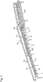
Die Transferfördereinrichtung umfasst einen Langstator-Linearmotorantrieb mit einer Vielzahl von einzeln und unabhängig voneinander bewegbaren Fördermitteln.The transfer conveyor device comprises a long-stator linear motor drive with a multiplicity of individually and independently movable conveying means.
Im Falle eines Langstator-Linearmotorantriebs verfügt die Transferfördereinrichtung über eine Vielzahl von einzeln bewegbaren Fördermitteln. Das einzelne und unabhängige Bewegen bezieht sich dabei sowohl auf die Position als auch auf die Geschwindigkeit der Fördermittel. Dabei sind die Fördermittel so ausgebildet, dass sie einen oder mehrere Behälter mit einem individuellen Weg-Zeit-Profil entlang einer vorgegebenen Transportstrecke zwischen der Übernahme von der Einlauffördereinrichtung und der Übergabe an die Auslauffördereinrichtung transportieren können. Insbesondere können die Fördermittel als Schlitten oder Läufer ausgebildet werden, welche jeweils ein oder mehrere Führungselemente zum Führen der Behälter aufweisen. Bei einem Langstator-Linearmotorantrieb, wie er im Stand der Technik an sich bekannt ist, werden die Fördermittel mit ihren Führungselementen durch magnetische Wechselwirkung mit einem oder mehreren Langstatoren einzeln und unabhängig voneinander bewegt. Zur Definition der jeweiligen Weg-Zeit-Profile der Fördermittel, und damit der geführten Behälter, kann die erfindungsgemäße Transferfördereinrichtung eine Steuer- und/oder Regeleinrichtung umfassen, welche die Fördermittel und/oder den Linearmotorantrieb entsprechend ansteuert. Die Anzahl der Fördermittel kann gemäß dem gewünschten Durchsatz an Behältern der Transferfördereinrichtung sowie in Abhängigkeit von einer Länge der Transportstrecke gewählt werden. Im Allgemeinen werden wenigstens so viele Fördermittel vorgesehen, dass die einlaufenden Behälter ohne Verzögerungen auf die auslaufenden Förderspuren aufgeteilt werden können.In the case of a long-stator linear motor drive, the transfer conveyor has a large number of individually movable conveyors. The individual and independent movement relates to both the position and the speed of the conveyor. There the conveying means are designed in such a way that they can transport one or more containers with an individual path-time profile along a specified transport route between the takeover from the infeed conveyor and the transfer to the outfeed conveyor. In particular, the conveying means can be designed as slides or runners which each have one or more guide elements for guiding the container. In the case of a long stator linear motor drive, as is known per se in the prior art, the conveying means with their guide elements are moved individually and independently of one another by magnetic interaction with one or more long stators. To define the respective path-time profiles of the conveying means, and thus the guided containers, the transfer conveying device according to the invention can include a control and / or regulating device which controls the conveying means and / or the linear motor drive accordingly. The number of conveying means can be selected according to the desired throughput of containers of the transfer conveyor device and as a function of a length of the transport route. In general, at least as many conveying means are provided that the incoming containers can be distributed to the outgoing conveying lanes without delays.
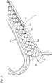
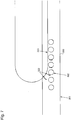
Die Vielzahl der Fördermittel mit ihren jeweiligen Führungselementen laufen erfindungsgemäß entlang einer Transportbahn der Transferfördereinrichtung um. Dabei ist die Form dieser Transportbahn grundsätzlich beliebig, solange ein Teil der Transportbahn derart zwischen der Einlauffördereinrichtung und der Auslauffördereinrichtung angeordnet ist, dass die Behälter aus dem Einlaufstrom von den Führungselementen übernommen und auf die auslaufenden Förderspuren verteilt werden können. Insbesondere können die Transportbahnen im Wesentlichen geschlossen sein, wobei im Wesentlichen geschlossen bedeutet, dass die jeweilige Transportbahn mindestens einen geschlossenen Weg für die jeweilige Vielzahl von Fördermitteln aufweist. Dies kann beispielsweise durch Bereitstellen einer Rückführstrecke als Teil der Transportbahn realisiert werden, wobei die Rückführstrecke ein Rückführen der Fördermittel zur Einlauffördereinrichtung nach Übergabe der Behälter an die Auslauffördereinrichtung ermöglicht. Neben einer Hauptstrecke sind dabei eine oder mehrere Nebenstrecken möglich, die mit der Hauptstrecke über Weichen verbunden sind (siehe unten). Entlang der Rückführstrecke werden die Fördermittel nicht nur zur Einlauffördereinrichtung zurückgeführt, sondern können dort auch gepuffert werden, falls Lücken im Einlaufstrom der Behälter auftreten sollten. Darüber hinaus muss nicht die gesamte jeweilige Transportbahn mit dem Linearmotorantrieb für die Fördermittel ausgestattet sein. Alternativ kann beispielsweise die Rückführstrecke mit einem kontinuierlichen Antrieb wie einem Transportriemen oder ähnlichem ausgestattet sein.According to the invention, the plurality of conveying means with their respective guide elements circulate along a transport path of the transfer conveying device. The shape of this transport path is basically arbitrary as long as part of the transport path is arranged between the infeed conveyor and the outfeed conveyor in such a way that the containers from the infeed flow can be taken over by the guide elements and distributed to the outflowing conveyor lanes. In particular, the transport paths can be essentially closed, whereby essentially closed means that the respective transport path has at least one closed path for the respective multiplicity of conveying means. This can be realized, for example, by providing a return path as part of the transport path, the return path enabling the conveying means to be returned to the infeed conveyor after the containers have been transferred to the outfeed conveyor. In addition to a main line, one or more secondary lines are possible, which are connected to the main line via switches (see below). Along the return path, the conveying means are not only returned to the infeed conveyor device, but can also be buffered there should gaps occur in the inlet flow of the containers. In addition, the entire respective transport path does not have to be equipped with the linear motor drive for the conveying means. Alternatively, for example, the return path can be equipped with a continuous drive such as a transport belt or the like.
Da die Fördermittel und damit die Führungselemente derart einzeln und unabhängig voneinander bewegt werden können, können aufeinanderfolgende Behälter mit einem beliebigen Teilungsabstand in Förderrichtung entlang der Transportstrecke der Transferfördereinrichtung transportiert werden. Insbesondere können die Behälter dabei nach einem vorgegebenen Verteilschema beliebig beschleunigt und/oder abgebremst werden, um sie auf die auslaufenden Förderspuren zu verteilen. Auch eventuelle Lücken im einlaufenden Behälterstrom können durch entsprechend beschleunigtes Führen des oder der nachfolgenden Behälter bzw. entsprechend verzögertes Führen des oder der vorauseilenden Behälter geschlossen werden, sodass stets ein lückenloser Auslaufstrom gebildet werden kann.Since the conveying means and thus the guide elements can be moved individually and independently of one another in this way, successive containers with any pitch can be made be transported in the conveying direction along the transport path of the transfer conveyor. In particular, the containers can be accelerated and / or decelerated at will according to a predetermined distribution scheme in order to distribute them to the outgoing conveyor lanes. Any gaps in the incoming container flow can also be closed by correspondingly accelerated guiding of the subsequent container (s) or correspondingly delayed guiding of the preceding container (s), so that an uninterrupted discharge flow can always be formed.
Bei einer Transferfördereinrichtung mit Langstator-Linearmotorantrieb kann die zwischen Einlauffördereinrichtung und Auslauffördereinrichtung liegende Transportstrecke bzw. Transferstrecke geradlinig oder auch zumindest teilweise gekrümmt sein. Dadurch können Einlauffördereinrichtung und Auslauffördereinrichtung in einer Linie angeordnet sein. Das Führen der Behälter mittels eines Langstator-Linearmotorantriebs erfolgt ebenso wie bei dem unten beschriebenen Führen mittels eines Riemen- oder Kettenantriebs, indem die zu führenden Behälter auf einer Förderfläche stehen, wobei es sich bei dieser Förderfläche insbesondere um ein Transportband der Auslauffördereinrichtung oder der Transferfördereinrichtung handeln kann.In the case of a transfer conveyor device with a long-stator linear motor drive, the transport path or transfer path located between the infeed conveyor device and the outfeed conveyor device can be straight or also at least partially curved. As a result, the inlet conveyor device and the outlet conveyor device can be arranged in a line. The containers are guided by means of a long stator linear motor drive in the same way as with the guide described below by means of a belt or chain drive, in that the containers to be guided are on a conveyor surface, this conveyor surface being in particular a conveyor belt of the discharge conveyor or the transfer conveyor can.
Zum Führen der Fördermittel des Langstator-Linearmotorantriebs entlang der jeweiligen Transportbahn kann die Transportbahn beispielsweise mindestens eine Führungsschiene und/oder einen Führungskanal aufweisen. Dementsprechend können die Fördermittel mindestens einen komplementären Führungskanal, einen Führungsstift und/oder eine oder mehrere geeignet angeordnete Führungsrollen aufweisen, welche z. B. mittels eines Spurkranzes auf der Führungsschiene der Transportbahn laufen. Eine Vielzahl alternativer Ausführungsformen, z. B. mittels Gleitlager, ist hierbei vorstellbar. Durch das Bereitstellen einer Führungsschiene an der Transportbahn kann ein reibungsarmes Leiten der Fördermittel entlang der Transportbahn ermöglicht werden. Darüber hinaus kann die Transportbahn über eine Lauffläche verfügen, auf welcher entsprechende Stützelemente, z. B. Stützrollen, abrollen bzw. gleiten können. Weiterhin kann die Transportbahn mindestens einen Sensor zur Bestimmung der Position der Fördermittel entlang der Transportbahn umfassen. Insbesondere kann durch regelmäßige und periodische Anordnung von Sensoren entlang zumindest eines Teilstücks der Transportbahn die Position eines Fördermittels auf diesem Teilstück der Transportbahn bestimmt werden. Alternativ kann die Positionsbestimmung der Fördermittel auch ohne zusätzliche Sensorik, beispielsweise mittels geberloser Regelung der Fördermittel (ELC - Encoderless Control), realisiert werden. Sensoren können als optische Sensoren, elektrische Sensoren, elektromagnetische Sensoren oder mechanische Sensoren ausgebildet sein. Solche Sensoren können beispielsweise im Vorlauf zur Übernahme der Behälter von dem Einlaufstrom vorgesehen sein, um eine Synchronisierung der Bewegung der Fördermittel, d.h. der Führungselemente, mit der Bewegung der aufzunehmenden Behälter zu erreichen. Dadurch und durch geeignetes Anordnen der Transportbahn zur Einlauffördereinrichtung können einzelne Behälter oder Gruppen von Behältern gezielt von dem Einlaufstrom übernommen werden.For guiding the conveying means of the long stator linear motor drive along the respective transport path, the transport path can for example have at least one guide rail and / or one guide channel. Accordingly, the conveying means can have at least one complementary guide channel, a guide pin and / or one or more suitably arranged guide rollers which, for. B. run by means of a flange on the guide rail of the transport track. A variety of alternative embodiments, e.g. B. by means of plain bearings is conceivable here. By providing a guide rail on the transport path, low-friction guiding of the conveying means along the transport path can be made possible. In addition, the transport track can have a running surface on which corresponding support elements, for. B. support rollers can roll or slide. Furthermore, the transport path can comprise at least one sensor for determining the position of the conveying means along the transport path. In particular, by regular and periodic arrangement of sensors along at least a section of the transport path, the position of a conveying means on this section of the transport path can be determined. Alternatively, the position of the conveying means can also be determined without additional sensors, for example by means of encoderless regulation of the conveying means (ELC - Encoderless Control). Sensors can be designed as optical sensors, electrical sensors, electromagnetic sensors or mechanical sensors. Such sensors can be provided, for example, in advance of the takeover of the containers from the inlet flow in order to synchronize the movement of the conveying means, ie the guide elements, with the movement of the ones to be picked up To reach container. As a result, and by suitably arranging the transport path to the infeed conveyor device, individual containers or groups of containers can be specifically taken over by the infeed flow.
Gemäß der vorliegenden Weiterbildung sind die Transportbahn und die Fördermittel des Langstator-Linearmotorantriebs derart ausgestaltet, dass die Fördermittel einzeln entlang der Transportstrecke geleitet werden können. Dies bedeutet, dass die Fördermittel je mindestens ein Reaktionselement aufweisen, welches mittels elektromagnetischer Wechselwirkung mit entlang der Transportbahn angeordneten Wechselwirkungselementen eine Kraft erfährt, durch welche das Fördermittel beschleunigt und somit bewegt werden kann. Durch gezieltes Ansteuern des Reaktionselements eines bestimmten Fördermittels und/oder eines oder mehrerer Wechselwirkungselemente in einem begrenzten Bereich der Transportbahn kann diese Kraftausübung auf ein bestimmtes Fördermittel beschränkt werden, wodurch das Fördermittel einzeln und unabhängig von anderen Fördermitteln entlang der Transportbahn geleitet werden kann.According to the present development, the transport track and the conveying means of the long stator linear motor drive are designed in such a way that the conveying means can be guided individually along the transport route. This means that the conveying means each have at least one reaction element which, by means of electromagnetic interaction with interaction elements arranged along the transport path, experiences a force by which the conveying means can be accelerated and thus moved. By targeted control of the reaction element of a certain conveyor and / or one or more interaction elements in a limited area of the transport path, this force exertion can be limited to a certain conveyor, whereby the conveyor can be guided individually and independently of other conveyors along the transport path.
Transportsysteme mit Linearmotorantrieb sind im Stand der Technik wohl bekannt. Allen Transportsystemen mit Linearmotorantrieb ist gemein, dass speziell dazu ausgebildete Transportelemente bzw. Fördermittel über magnetische Wechselwirkung mit dem oder den Langstatoren bzw. Linearmotorsträngen eines oder mehrerer Linearmotoren entlang einer oder mehrerer Führungsschienen bewegt werden.Linear motor drive transport systems are well known in the art. All transport systems with linear motor drives have in common that specially designed transport elements or conveying means are moved along one or more guide rails via magnetic interaction with the long stators or linear motor strands of one or more linear motors.
Im Fall der Verwendung eines Linearmotorantriebs zum Führen der Behälter in der Transferfördereinrichtung sind also die Fördermittel und zumindest der Teil der jeweiligen Transportbahn entlang der Transportstrecke derart ausgebildet, dass die Fördermittel im Bereich der Transportstrecke mittels einer magnetischen Kraft, vorzugsweise in Wechselwirkung mit der Transportbahn, bewegt werden können. Der entsprechende Teil der Transportbahn kann insbesondere mit einem magnetischen Linearantrieb, zum Beispiel in Form eines synchronen oder asynchronen Linearmotors, ausgestattet sein. Dazu wird der entsprechende Abschnitt der Transportbahn mit einer Vielzahl von elektrischen Wicklungen in Form von einzeln ansteuerbaren Elektromagneten ausgerüstet. Um eine magnetische Wechselwirkung zwischen dem Fördermittel und den einzeln ansteuerbaren Elektromagneten der Transportbahn zu erzeugen, kann das Fördermittel mit einem oder mehreren Permanentmagneten bzw. nicht schaltenden Elektromagneten oder Eisenkernen ausgestattet werden.If a linear motor drive is used to guide the containers in the transfer conveyor, the conveyor and at least the part of the respective transport path along the transport path are designed in such a way that the conveyor moves in the area of the transport path by means of a magnetic force, preferably in interaction with the transport path can be. The corresponding part of the transport path can in particular be equipped with a magnetic linear drive, for example in the form of a synchronous or asynchronous linear motor. For this purpose, the corresponding section of the transport path is equipped with a large number of electrical windings in the form of individually controllable electromagnets. In order to generate a magnetic interaction between the conveying means and the individually controllable electromagnets of the transport path, the conveying means can be equipped with one or more permanent magnets or non-switching electromagnets or iron cores.
In einer Ausführung kann das Fördermittel als ein passives Fördermittel ausgeführt sein, welches durch Wechselwirkung mit den von den einzeln ansteuerbaren Elektromagneten der Transportbahn erzeugten elektromagnetischen Wechselfeldern bewegt wird. Der mindestens eine Permanentmagnet bzw. nicht schaltende Elektromagnet bzw. Eisenkern des Fördermittels bildet somit das oben erwähnte Reaktionselement, während die einzeln ansteuerbaren Elektromagnete der Transportbahn die oben erwähnten Wechselwirkungselemente bilden. Bevorzugt ist bei Verwendung von passiven Fördermitteln eine Lokalisierungseinheit an der Transportbahn angebracht, um die Lage wenigstens eines Fördermittels und bevorzugt aller Fördermittel zu ermitteln und an eine Steuerung der Elektromagnete der Transportbahn weiterzugeben. Die Lokalisierungseinheit kann insbesondere durch die oben beschriebenen Sensoren realisiert werden. Die Stromstärke durch die elektrischen Wicklungen der Transportbahn kann von der Steuerung in Abhängigkeit von einem Kraftbedarf des zu bewegenden Fördermittels automatisch angepasst werden. Durch individuelles Regeln der Stromstärke durch einzelne Wicklungen der Transportbahn kann das Fördermittel außerdem beschleunigt, abgebremst oder mit einer konstanten vorgegebenen Geschwindigkeit bewegt werden.In one embodiment, the conveying means can be designed as a passive conveying means which, through interaction with the electromagnets that can be individually controlled by the Transport path generated electromagnetic alternating fields is moved. The at least one permanent magnet or non-switching electromagnet or iron core of the conveying means thus forms the above-mentioned reaction element, while the individually controllable electromagnets of the transport path form the above-mentioned interaction elements. When using passive conveying means, a localization unit is preferably attached to the transport track in order to determine the position of at least one conveying means and preferably all of the conveying means and to pass it on to a control of the electromagnets of the transport track. The localization unit can in particular be implemented by the sensors described above. The strength of the current through the electrical windings of the transport path can be automatically adjusted by the control depending on the power requirement of the conveying means to be moved. By individually regulating the amperage through individual windings of the transport path, the conveying means can also be accelerated, decelerated or moved at a constant predetermined speed.
Bei einer alternativen Ausführungsform ist das Fördermittel als aktives Fördermittel mit elektrischen Wicklungen versehen, welche die für den Antrieb notwendigen magnetischen Wechselfelder aufbringen können. Entsprechend wird der Abschnitt der Transportbahn mit Permanentmagneten bzw. nicht schaltenden Elektromagneten versehen. Hierbei können sowohl die für den Antrieb nötige elektrische Energie als auch für die Steuerung nötigen Signale via Induktionsübertragung auf die einzelnen Fördermittel übertragen werden. Die Steuerung kann sich demnach dezentral auf den einzelnen Fördermitteln befinden oder auch zentral in einer eigenen Steuereinheit untergebracht sein. Alternativ dazu kann die nötige elektrische Energie über eine entlang der Transportbahn angeordnete Leitung auf die Fördermittel übertragen werden. Des Weiteren ist eine Kombination einer Ausführung des Fördermittels als aktives Fördermittel mit einer Transportbahn mit einzeln ansteuerbaren Elektromagneten denkbar.In an alternative embodiment, the conveying means is provided as an active conveying means with electrical windings which can apply the alternating magnetic fields necessary for the drive. Correspondingly, the section of the transport path is provided with permanent magnets or non-switching electromagnets. Both the electrical energy required for the drive and the signals required for the control can be transmitted to the individual conveying means via induction transmission. The control can therefore be located decentrally on the individual conveying means or also be housed centrally in a separate control unit. Alternatively, the necessary electrical energy can be transmitted to the conveying means via a line arranged along the transport path. Furthermore, a combination of an embodiment of the conveying means as active conveying means with a transport path with individually controllable electromagnets is conceivable.
Zum Einsatz eines Linearmotorantriebs kann die jeweilige Transportbahn einen oder mehrere Linearmotorstränge aufweisen, die als Langstatoren von, insbesondere synchronen, Linearmotoren ausgebildet sind. In einer alternativen Ausführung können die Linearmotorstränge auch als asynchrone Linearmotoren ausgebildet sein, wobei der mindestens eine Permanentmagnet und/oder nicht schaltende Elektromagnet des Reaktionselements des Fördermittels und/oder ein elektrisch leitendes Element des Fördermittels, z. B. in Form einer metallischen Platte, an welcher der Permanentmagnet und/oder nicht schaltende Elektromagnet angebracht sind, als elektrische Leiter für die Induktion durch die asynchronen Linearmotoren fungieren.For the use of a linear motor drive, the respective transport track can have one or more linear motor strings, which are designed as long stators of, in particular synchronous, linear motors. In an alternative embodiment, the linear motor trains can also be designed as asynchronous linear motors, the at least one permanent magnet and / or non-switching electromagnet of the reaction element of the conveyor and / or an electrically conductive element of the conveyor, e.g. B. in the form of a metallic plate, to which the permanent magnet and / or non-switching electromagnet are attached, act as an electrical conductor for the induction by the asynchronous linear motors.
Neben dem oben beschriebenen, als Magnettrasse ausgebildeten Teil der Transportbahn entlang der Transferstrecke zwischen Übernahmepunkt und Übergabepunkt kann die Transportbahn außerhalb der Transferstrecke weiterhin wenigstens eine Teilstrecke, beispielsweise die Rückführstrecke, umfassen, entlang derer die Fördermittel mit einer konstanten Geschwindigkeit bewegt werden. Die Teilstrecke kann hierzu eine Antriebsvorrichtung in Form eines Transportbandes, einer Transportkette oder ähnlichem umfassen. Durch Kombination einer Transportstrecke mit Magnetantrieb und einer Rückführstrecke mit einem mechanischen Antrieb können Installationskosten der gesamten Transferfördereinrichtung gesenkt werden.In addition to the part of the transport track, which is designed as a magnetic route, along the transfer route between the takeover point and the transfer point, the transport track outside the transfer path furthermore comprise at least one partial path, for example the return path, along which the conveying means are moved at a constant speed. For this purpose, the section can comprise a drive device in the form of a conveyor belt, a conveyor chain or the like. By combining a transport path with a magnetic drive and a return path with a mechanical drive, installation costs for the entire transfer conveyor can be reduced.
In einer Weiterbildung kann das Fördermittel vollmagnetisch oder teilweise magnetisch und teilweise mechanisch oder vollmechanisch an der Transportbahn gelagert sein. Bei vollmagnetischer Lagerung ist der oben beschriebene Teil der Transportbahn als Magnetschwebebahn ausgebildet, wobei elektrische Wicklungen in der Transportbahn und/oder dem Fördermittel vorgesehen sind, welche eine magnetische Levitation des Fördermittels über der Transportbahn bewirken. Dadurch lässt sich die Reibung zwischen dem Fördermittel und der Transportbahn auf ein Minimum reduzieren. Bei teilweise magnetischer und teilweise mechanischer Lagerung kann das Fördermittel zusätzlich ein oder mehrere Stützelemente, zum Beispiel in Form von Stützrollen und/oder Führungsrollen aufweisen. Die zusätzlichen Stützelemente rollen oder gleiten dabei auf einer Lauffläche bzw. Führungsschiene der Transportbahn. Bei vollmechanischer Lagerung kann das Fördermittel ausschließlich durch das beschriebene mindestens eine Stützelement gelagert sein. Ergänzend oder alternativ hierzu kann eine Lagerung auch pneumatisch erfolgen, wobei die Transportbahn in dem entsprechenden Teilstück als Luftschwebebahn ausgeführt ist. Bei pneumatischer Lagerung ergibt sich wie auch bei vollständig magnetischer Lagerung eine Minimierung der Reibung zwischen dem Fördermittel und der Transportbahn.In a further development, the conveying means can be supported on the transport path in a fully magnetic or partially magnetic and partially mechanical or fully mechanical manner. In the case of fully magnetic storage, the part of the transport path described above is designed as a magnetic levitation train, with electrical windings being provided in the transport path and / or the conveyor, which cause magnetic levitation of the conveyor above the transport path. This allows the friction between the conveyor and the transport path to be reduced to a minimum. In the case of partially magnetic and partially mechanical mounting, the conveying means can additionally have one or more support elements, for example in the form of support rollers and / or guide rollers. The additional support elements roll or slide on a running surface or guide rail of the transport track. In the case of fully mechanical mounting, the conveying means can be mounted exclusively by the at least one support element described. In addition or as an alternative to this, storage can also take place pneumatically, with the transport path in the corresponding section being designed as an air suspension path. With pneumatic mounting, as with completely magnetic mounting, there is a minimization of the friction between the conveying means and the transport path.
Die Transferfördereinrichtung kann weiterhin eine Steuer- und/oder Regeleinrichtung, insbesondere einen Prozessrechner, zum Steuern des mindestens einen Fördermittels umfassen. Die Steuer- und/oder Regeleinrichtung kann dabei durch eine zentrale Steuereinheit und/oder durch dezentral an den Fördermitteln angeordnete Steuereinheiten realisiert werden. Die eine oder mehrere Steuereinheiten können dabei derart ausgebildet sein, dass sie die elektrischen Wicklungen der Transportbahn und/oder der Fördermittel derart individuell steuern und/oder regeln, dass die Fördermittel die mittels der jeweiligen Führungselemente übernommenen Behälter gezielt zur jeweiligen auslaufenden Förderspur führen.The transfer conveying device can furthermore comprise a control and / or regulating device, in particular a process computer, for controlling the at least one conveying means. The control and / or regulating device can be implemented by a central control unit and / or by control units arranged decentrally on the conveying means. The one or more control units can be designed in such a way that they individually control and / or regulate the electrical windings of the transport path and / or the conveying means in such a way that the conveying means specifically guide the containers taken over by the respective guide elements to the respective outgoing conveyor lane.
Alternativ oder zusätzlich kann die Transferfördereinrichtung einen Riemen- oder Kettenantrieb umfassen, beispielsweise um, wie oben beschrieben, die unbeladenen Fördermittel entlang der Rückführstrecke zur Übernahmestelle an der Einlauffördereinrichtung zurück zu führen. Unter Inkaufnahme einer geringeren Flexibilität kann aber auch das Führen der Behälter entlang der Transportstrecke durch einen Riemen- oder Kettenantrieb bewältigt werden. Dabei sind die Vielzahl von Führungselementen zum Übernehmen der Behälter von dem Einlaufstrom in einem konstanten Abstand voneinander derart an dem Transportriemen bzw. der Transportkette angeordnet, dass sie bei geeigneter Umlaufgeschwindigkeit des Transportriemens bzw. der Transportkette in den einlaufenden Behälterstrom eintauchen und derart zwischen die Behälter des Einlaufstroms greifen, dass diese durch mechanischen Kontakt mit den Führungselementen zu der Auslauffördereinrichtung geführt werden können.As an alternative or in addition, the transfer conveyor device can comprise a belt or chain drive, for example in order, as described above, to return the unloaded conveyor device along the return path to the transfer point on the infeed conveyor device. However, while accepting less flexibility, the containers can also be guided along the transport route by means of a belt or chain drive. They are there A large number of guide elements for taking over the containers from the inlet stream are arranged at a constant distance from one another on the conveyor belt or the conveyor chain in such a way that, at a suitable speed of rotation of the conveyor belt or the conveyor chain, they dip into the incoming container stream and thus grip between the containers of the inlet stream, that these can be guided to the discharge conveyor device by mechanical contact with the guide elements.
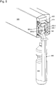
Unabhängig davon, ob die Führungselemente als Teil einzeln bewegbarer Fördermittel eines Langstator-Linearmotorantriebs vorgesehen sind oder über einen Riemen- oder Kettenantrieb angetrieben werden, können die Führungselemente jeweils wenigstens ein, insbesondere gesteuert verriegelbares und/oder gesteuert entriegelbares Anschlagelement aufweisen, das derart ausgebildet ist, dass es über mechanischen Eingriff mit wenigstens einem Behälter zum Abbremsen dieses Behälters verwendet werden kann. Das Anschlagelement kann dabei entsprechend der Form und Größe der zu führenden Behälter ausgebildet sein, beispielsweise als Anschlagplatte oder Anschlagbalken, und insbesondere derart ausgebildet sein, dass ein Verkippen der geführten Behälter während des Abbremsens verhindert werden kann. Darüber hinaus kann das Anschlagelement derart ausgebildet sein, dass auch Behälter unterschiedlicher Größe und/oder Form ohne Wechsel des Anschlagelements sicher geführt werden können. Um die geführten Behälter gezielt an die gewünschten Förderspuren der Auslauffördereinrichtung übergeben zu können, kann das Anschlagelement optional mit einem Verriegelungsmechanismus, beispielsweise in Form eines Drehriegels, ausgestattet sein. Nachdem das Anschlagelement in die Lücke zwischen zwei aufeinanderfolgenden Behältern des Einlaufstroms eingetaucht ist, kann dieser Verriegelungsmechanismus, beispielsweise über eine stationäre Nocke, betätigt werden, um den übernommenen Behälter vor dem Herausrutschen aus dem Führungselement zu schützen. Ist der Behälter an der gewünschten Förderspur angelangt, kann der Verriegelungsmechanismus, beispielsweise mittels einer stationären und schaltbaren Nocke, geöffnet werden, um den Behälter freizugeben. Das Anschlagelement kann besonders vorteilhaft in Kombination mit einem Transportband der Transferfördereinrichtung bzw. der Auslauffördereinrichtung eingesetzt werden, welches mit einer solchen Geschwindigkeit betrieben wird, dass der von dem Transportband beförderte Behälter gegen das Anschlagelement gefahren wird. Durch geeignete Relativgeschwindigkeit des Führungselements zum Transportband können die geführten Behälter gezielt auf die auslaufenden Förderspuren verteilt werden, wobei gleichzeitig Gruppen von Behältern gebildet werden können.Regardless of whether the guide elements are provided as part of individually movable conveying means of a long stator linear motor drive or are driven via a belt or chain drive, the guide elements can each have at least one stop element, in particular that can be locked and / or unlocked in a controlled manner, which is designed in such a way that that it can be used to brake this container via mechanical engagement with at least one container. The stop element can be designed according to the shape and size of the containers to be guided, for example as a stop plate or stop bar, and in particular be designed in such a way that tilting of the guided containers can be prevented during braking. In addition, the stop element can be designed in such a way that containers of different sizes and / or shapes can also be safely guided without changing the stop element. In order to be able to transfer the guided containers in a targeted manner to the desired conveyor tracks of the discharge conveyor device, the stop element can optionally be equipped with a locking mechanism, for example in the form of a rotary bolt. After the stop element is immersed in the gap between two successive containers of the inlet flow, this locking mechanism can be actuated, for example via a stationary cam, in order to protect the container taken over from slipping out of the guide element. Once the container has reached the desired conveyor lane, the locking mechanism can be opened, for example by means of a stationary and switchable cam, in order to release the container. The stop element can be used particularly advantageously in combination with a conveyor belt of the transfer conveyor or the outlet conveyor, which is operated at such a speed that the container conveyed by the conveyor belt is driven against the stop element. By means of a suitable relative speed of the guide element to the conveyor belt, the guided containers can be distributed in a targeted manner to the outgoing conveyor lanes, whereby groups of containers can be formed at the same time.
In dem Fall, dass die Transferfördereinrichtung einen Langstator-Linearmotorantrieb aufweist, können die Führungselemente alternativ oder zusätzlich je wenigstens ein Schubelement aufweisen, das derart ausgebildet ist, dass es über mechanischen Eingriff mit wenigstens einem Behälter zum seitenstabilen Vorschieben dieses Behälters verwendet werden kann. Das Schubelement kann dabei entsprechend der Form und/oder Größe der zu führenden Behälter derart ausgebildet sein, dass die zu führenden Behälter seitenstabil, d. h. ohne seitliches Herausrutschen oder Kippen, von der Übernahmestelle zur Übergabestelle geschoben werden können. Auch hier sind Ausbildungen der Schubelemente möglich, die Behälter unterschiedlicher Formen und Größen seitenstabil führen können. Mittels des Langstator-Linearmotorantriebs können die Behälter durch mechanischen Kontakt mit den Schubelementen mit einer gewünschten Geschwindigkeit über eine Förderfläche geschoben werden. Beispielsweise können die Behälter gezielt von einem Transportband der Einlauffördereinrichtung an den entsprechenden Stellen auf an dieses Transportband angrenzende parallel angeordnete Transportbänder der Auslauffördereinrichtung geschoben werden.In the event that the transfer conveyor device has a long-stator linear motor drive, the guide elements can alternatively or additionally each have at least one thrust element which is designed such that it is mechanically engaged with at least one Container can be used for laterally stable advancement of this container. The pusher element can be designed according to the shape and / or size of the container to be guided in such a way that the container to be guided can be pushed from the transfer point to the transfer point in a laterally stable manner, ie without slipping out sideways or tilting. Here, too, designs of the pushing elements are possible, which can guide containers of different shapes and sizes in a laterally stable manner. By means of the long stator linear motor drive, the containers can be pushed over a conveying surface at a desired speed by mechanical contact with the pushing elements. For example, the containers can be pushed in a targeted manner from a conveyor belt of the infeed conveyor at the appropriate points onto conveyor belts of the outfeed conveyor that are adjacent to this conveyor belt and are arranged in parallel.
Gemäß einer speziellen Weiterbildung kann die Transferfördereinrichtung weiterhin eine Vielzahl von steuerbaren Weichen aufweisen, die eine Hauptstrecke der Transferfördereinrichtung mit einer Vielzahl den auslaufenden Behälterspuren zugeordneter Nebenstrecken verbindet. In dieser Weiterbildung umfasst die Transportbahn des Langstator-Linearmotorantriebs neben der Hauptstrecke eine Vielzahl von Nebenstrecken, die mit der Hauptstrecke über Weichen verbunden sind. Über diese Weichen können die Fördermittel, und mit ihnen die geführten Behälter, gezielt auf die Nebenstrecken ausgeleitet werden, die der jeweils gewünschten Förderspur, zu der der Behälter geführt werden soll, zugeordnet sind. Nach Übergabe der Behälter werden die nunmehr unbeladenen Fördermittel über weitere Weichen wieder in die Hauptstrecke der Transportbahn eingeleitet und anschließend zur Einlauffördereinrichtung zurückgeführt.According to a special development, the transfer conveyor device can furthermore have a plurality of controllable switches that connect a main section of the transfer conveyor device with a plurality of secondary sections assigned to the outgoing container lanes. In this development, the transport path of the long stator linear motor drive comprises, in addition to the main line, a large number of secondary lines that are connected to the main line via switches. Via these switches, the conveying means, and with them the guided containers, can be directed specifically to the branch lines that are assigned to the respectively desired conveyor track to which the container is to be guided. After the containers have been handed over, the now unloaded conveying means are fed back into the main section of the transport path via further switches and then returned to the infeed conveyor.
Die Transferfördereinrichtung weist weiterhin wenigstens eine Teilstrecke auf, die die Auslauffördereinrichtung, d. h. deren Förderspuren, unter einem Winkel α kreuzt, der größer als 0° und kleiner als 90° ist, wobei der Winkel α insbesondere in etwa durch die Formel cosα = vauslvtrans mit einer konstanten Fördergeschwindigkeit vaus der Behälter im Auslaufstrom und einer konstanten Fördergeschwindigkeit vtrans der Behälter entlang der Teilstrecke der Transferfördereinrichtung gegeben sein kann. Die Teilstrecke kann dabei die gesamte, oben beschriebene Transportstrecke zwischen dem Übernahmepunkt für die Übernahme der Behälter von der Einlauffördereinrichtung und dem (letzten) Übergabepunkt für die Übergabe der Behälter an die Auslauffördereinrichtung umfassen, oder aber nur den Teil der Transportstrecke im Bereich der Übergabepunkte. Gemäß dieser Weiterbildung kreuzt diese Teilstrecke die Auslauffördereinrichtung unter einem spitzen Winkel a. Bei einer solchen Anordnung können die von der Transferfördereinrichtung geführten Behälter gezielt zu den jeweiligen auslaufenden Behälterspuren geführt werden, indem sie beispielsweise mittels der Führungselemente entsprechend schräg über die Gruppe der parallel laufenden Förderspuren geführt werden, um an der gewünschten Förderspur freigegeben zu werden. Gibt man eine konstante Fördergeschwindigkeit Vaus der Behälter in den Förderspuren des Auslaufstroms vor und weiterhin eine konstante Fördergeschwindigkeit vtrans der Behälter entlang der Teilstrecke der Transferfördereinrichtung, so können aufeinanderfolgende Behälter derart auf die Förderspuren verteilt werden, dass sie bereits gruppiert abgefördert werden, wenn dieser Winkel α in etwa durch die Formel cos α = vaus /vtrans gegeben ist. Dabei bedeutet "in etwa" in diesem Zusammenhang, dass der Winkel innerhalb von Installationstoleranzen der genannten Bedingung genügt. Bei anderen Winkeln kann diese Gruppierung, beispielsweise mittels der unten beschriebenen Weiterbildung der Auslauffördereinrichtung nachträglich hergestellt werden.The transfer conveyor further comprises at least one leg, the outlet conveyor, that the conveyor tracks, α intersects at an angle greater than 0 ° and smaller than 90 °, wherein the angle α in particular approximately by the formula cos α = v from lv trans with a constant conveying speed v out of the container in the outlet stream and a constant conveying speed v trans the container along the section of the transfer conveyor can be given. The partial route can include the entire transport route described above between the takeover point for taking over the containers from the infeed conveyor and the (last) handover point for handing over the containers to the outfeed conveyor, or only the part of the transport route in the area of the transfer points. According to this development, this section crosses the discharge conveyor device at an acute angle a. With such an arrangement, the containers guided by the transfer conveyor can be directed to the respective outgoing container tracks are guided by being guided, for example by means of the guide elements, correspondingly at an incline over the group of conveyor tracks running in parallel in order to be released at the desired conveyor track. If you specify a constant conveying speed V from the container in the conveying lanes of the discharge stream and a constant conveying speed v trans of the containers along the section of the transfer conveyor, then successive containers can be distributed to the conveying lanes in such a way that they are already conveyed away in groups when this Angle α is roughly given by the formula cos α = v out / v trans . In this context, “approximately” means that the angle satisfies the stated condition within installation tolerances. In the case of other angles, this grouping can be established subsequently, for example by means of the further development of the discharge conveyor device described below.
Gemäß einer Weiterbildung kann die Auslauffördereinrichtung weiterhin ein Paar parallel zueinander angeordneter Langstator-Linearmotorantriebe mit einer Vielzahl von paarweise durch ein Querelement, insbesondere einen Anlaufbalken, miteinander verbundenen Fördermitteln umfassen. Die derart angeordneten Linearmotorantriebe sind dabei dem Bereich der Auslauffördereinrichtung, in dem die Behälter auf die Förderspuren verteilt werden, prozesstechnisch nachgeordnet, sodass noch nicht gruppierte Behälter auf den Förderspuren durch gezieltes Bewegen der Paare von Fördermitteln zu Gruppen zusammengefasst werden können. Dazu können die noch nicht senkrecht zur Förderrichtung in einer Linie ausgerichteten Behälter mittels des Querelements ausgerichtet werden. Beispielsweise können die durch das oder die Transportbänder der Auslauffördereinrichtung schneller als die Querelemente beförderten Behälter gegen diese Querelemente anlaufen und somit abgebremst werden. Andererseits können nachlaufende Behälter durch ein schneller laufendes Querelement angeschoben werden, bis sie mit den vorauseilenden Behältern in einer Linie liegen. Dazu können die die Paare bildenden Fördermittel der Linearmotorantriebe mittels einer Steuer- und/oder Regeleinheit, auch unabhängig voneinander, entsprechend bewegt werden. Die Transportbahnen der Linearmotorantriebe können zum Rückführen der Fördermittel Rückführstrecken in einer vertikal versetzten Ebene zur Transportebene der Behälter aufweisen. Die Querelemente, insbesondere in Form von Anlaufbalken, können erneut derart ausgebildet sein, dass ein Verkippen der Behälter während des Gruppierens vermieden werden kann. Darüber hinaus können die Querelemente gelenkig an den jeweiligen Fördermitteln gelagert sein, sodass die Fördermittel der Paare vorübergehend mit unterschiedlichen Geschwindigkeiten bewegt werden können, um eine Schrägstellung der Querelemente in Bezug auf die Senkrechte zur Förderrichtung bewirken zu können. Nach Bedarf können die Querelemente mit variabler Länge, beispielsweise mittels eines Federmechanismus ausgebildet werden.According to a further development, the outfeed conveyor device can furthermore comprise a pair of long-stator linear motor drives arranged parallel to one another with a multiplicity of conveyor means connected to one another in pairs by a transverse element, in particular a run-up bar. The linear motor drives arranged in this way are process-oriented downstream of the area of the discharge conveyor in which the containers are distributed on the conveyor lanes, so that containers that have not yet been grouped on the conveyor lanes can be combined into groups by moving the pairs of conveyors in a targeted manner. For this purpose, the containers that are not yet aligned in a line perpendicular to the conveying direction can be aligned by means of the transverse element. For example, the containers conveyed faster than the transverse elements by the conveyor belt or belts of the discharge conveyor can run against these transverse elements and thus be braked. On the other hand, trailing containers can be pushed by a faster moving transverse element until they are in line with the leading containers. For this purpose, the conveyor means of the linear motor drives that form the pairs can be moved accordingly by means of a control and / or regulating unit, also independently of one another. The transport tracks of the linear motor drives can have return sections in a vertically offset plane to the transport plane of the containers for returning the conveying means. The transverse elements, in particular in the form of run-up bars, can again be designed in such a way that tilting of the containers during grouping can be avoided. In addition, the transverse elements can be articulated on the respective conveying means, so that the conveying means of the pairs can be moved temporarily at different speeds in order to be able to effect an inclination of the transverse elements in relation to the perpendicular to the conveying direction. If required, the transverse elements can be designed with a variable length, for example by means of a spring mechanism.
Die oben genannten Aufgaben werden auch durch ein Verfahren zum Verteilen und Gruppieren von Behältern in einer Behälterbehandlungsanlage gemäß Anspruch 8 gelöst. Vorteilhafte Weiterbildungen sind Gegenstand der abhängigen Ansprüche.The above-mentioned objects are also achieved by a method for distributing and grouping containers in a container treatment plant according to claim 8. Advantageous further developments are the subject of the dependent claims.
Dabei können dieselben Variationen und Weiterbildungen, die oben im Zusammenhang mit der erfindungsgemäßen Vorrichtung beschrieben wurden, auch auf das Verfahren zum Verteilen und Gruppieren von Behältern angewendet werden. Insbesondere kann die Transferfördereinrichtung derart ausgebildet und bzgl. der Einlauf- und Auslauffördereinrichtungen angeordnet sein, dass die umlaufenden Führungselemente je einen oder mehrere Behälter aus dem Einlaufstrom übernehmen und gezielt zu der jeweils gewünschten Förderspur der Auslauffördereinrichtung führen können. Dazu werden die Führungselemente mittels einer Steuer- und/oder Regeleinheit derart bewegt, dass sie im Bereich der Übernahme der Behälter synchron mit den Behältern im Einlaufstrom bewegt werden. Durch Annähern der Führungselemente an den Einlaufstrom werden diese dann in mechanischen Eingriff mit den Behältern gebracht, sodass die Transferfördereinrichtung die Kontrolle über den Transport der Behälter, insbesondere deren Geschwindigkeit, übernimmt. Sowohl in der Einlauffördereinrichtung als auch in der Auslauffördereinrichtung werden die Behälter mit Transportbändern stehend befördert. Während dies in der Einlauffördereinrichtung erfindungsgemäß einspurig geschieht, erfolgt der Transport in der Auslauffördereinrichtung mehrspurig, je nach gewünschter Behälterverteilung bzw. Gebindegröße. Dabei kann der mehrspurige Behältertransport wie oben beschrieben mittels eines einzigen Transportbandes oder einer entsprechenden Anzahl von parallel angeordneten Transportbändern erfolgen.The same variations and developments that were described above in connection with the device according to the invention can also be applied to the method for distributing and grouping containers. In particular, the transfer conveyor can be designed and arranged with respect to the inlet and outlet conveyor devices so that the revolving guide elements each take one or more containers from the inlet flow and can lead them selectively to the desired conveyor track of the outlet conveyor. For this purpose, the guide elements are moved by means of a control and / or regulating unit in such a way that they are moved synchronously with the containers in the inlet flow in the area where the containers are taken over. By bringing the guide elements closer to the inlet flow, they are then brought into mechanical engagement with the containers, so that the transfer conveyor takes over control of the transport of the containers, in particular their speed. Both in the infeed conveyor device and in the outfeed conveyor device, the containers are conveyed upright with conveyor belts. While this takes place in a single lane in the infeed conveyor device according to the invention, the transport in the outfeed conveyor device takes place in multiple lanes, depending on the desired container distribution or container size. The multi-lane container transport can be carried out as described above by means of a single conveyor belt or a corresponding number of conveyor belts arranged in parallel.
Das Verteilen der Behälter mittels der Transferfördereinrichtung erfolgt erfindungsgemäß, indem die Behälter über mechanischen Kontakt mit den Führungselementen gezielt zu den gewünschten auslaufenden Förderspuren bewegt werden. Dabei kann die Bewegung der Behälter im Bereich der Transferstrecke durch Kombination eines Vorschiebens und/oder Abbremsens der Behälter mittels der Führungselemente mit einem zugrunde liegenden Transport der Behälter, beispielsweise durch ein Transportband der Transferfördereinrichtung bzw. der Auslauffördereinrichtung, erzeugt werden. Zum Verteilen der Behälter können diese insbesondere quer über die nicht gewünschten Förderspuren der Auslauffördereinrichtung geschoben oder geführt werden. Nachdem die Behälter durch Aufheben des mechanischen Kontakts mit den Führungselementen an die auslaufenden Förderspuren übergeben wurden, werden die nunmehr unbeladenen Führungselemente umlaufend zur Übernahmestelle zurückgeführt.According to the invention, the containers are distributed by means of the transfer conveyor device in that the containers are moved in a targeted manner to the desired outgoing conveyor tracks via mechanical contact with the guide elements. The movement of the containers in the area of the transfer path can be generated by a combination of advancing and / or braking the container by means of the guide elements with an underlying transport of the container, for example by a conveyor belt of the transfer conveyor or the outlet conveyor. In order to distribute the containers, they can in particular be pushed or guided across the undesired conveying tracks of the discharge conveyor. After the containers have been transferred to the outgoing conveyor lanes by breaking the mechanical contact with the guide elements, the now unloaded guide elements are circulated back to the transfer point.
Gemäß einer Weiterbildung können die Behälter bei der Übernahme der Behälter von dem Einlaufstrom vereinzelt werden. Dies ist besonders dann von Vorteil, wenn die Behälter einzeln den gewünschten Förderspuren zugeführt werden sollen. Die Vereinzelung der Behälter kann dabei insbesondere durch die Führungselemente selbst, bzw. deren mechanischen Eingriff mit den Behältern erfolgen. Wie oben erwähnt werden die Führungselemente dabei derart synchron mit den Behältern im Einlaufstrom bewegt, dass sie durch Annäherung an die Einlauffördereinrichtung jeweils zwischen zwei aufeinanderfolgende Behälter eintauchen. Durch Ausüben einer Kraft über die Führungselemente auf die Behälter werden letztere somit einzeln geführt und können gezielt an eine gewünschte Stelle bewegt werden.According to a development, the containers can be separated from the inlet flow when the containers are taken over. This is particularly advantageous when the containers are to be fed individually to the desired conveyor lanes. The containers can be separated by the guide elements themselves or their mechanical engagement with the containers. As mentioned above, the guide elements are moved synchronously with the containers in the inlet flow in such a way that they each immerse between two consecutive containers when they approach the inlet conveyor. By exerting a force via the guide elements on the containers, the latter are thus guided individually and can be moved to a desired location in a targeted manner.
Erfindungsgemäß werden die Behälter mittels eines Langstator-Linearmotorantriebs mit einer Vielzahl von einzeln und unabhängig voneinander bewegbaren Fördermitteln verteilt. Dabei können dieselben Weiterbildungen und Variationen, die zuvor im Zusammenhang mit dem Linearmotorantrieb beschrieben wurden, auch hier zum Einsatz kommen. Insbesondere können die Fördermittel derart individuell mittels einer Steuer- und/oder Regeleinheit der Transferfördereinrichtung bewegt werden, dass ihre Führungselemente einzelne Behälter oder Gruppen von Behältern aus dem Einlaufstrom übernehmen und gezielt zu den gewünschten Förderspuren führen. Dabei können eventuelle Lücken im Einlaufstrom dadurch geschlossen werden, dass die Fördermittel bei Bedarf auf den nächsten Behälter am Übergabepunkt warten. Durch Beschleunigen der nachlaufenden Fördermittel und/oder Verzögern der vorauseilenden Fördermittel kann die Lücke dann wieder zusammengefahren werden. Eine solche Flexibilität ist zwar bei Verwendung eines Riemen- oder Kettenantriebs nicht gegeben. Dafür reduzieren sich jedoch die Installations- und Betriebskosten. Auch die mittels Riemen- oder Kettenantriebs umlaufend bewegten Führungselemente können mit den Behältern im Einlaufstrom synchronisiert werden.According to the invention, the containers are distributed by means of a long stator linear motor drive with a large number of individually and independently movable conveying means. The same developments and variations that were previously described in connection with the linear motor drive can also be used here. In particular, the conveying means can be moved individually by means of a control and / or regulating unit of the transfer conveying device in such a way that their guide elements take over individual containers or groups of containers from the inlet flow and lead them specifically to the desired conveying tracks. Any gaps in the inlet flow can be closed by having the conveyor wait for the next container at the transfer point if necessary. The gap can then be closed again by accelerating the following conveying means and / or delaying the leading conveying means. Such flexibility is not given when using a belt or chain drive. However, the installation and operating costs are reduced. The guide elements, which are moved around by means of belt or chain drives, can also be synchronized with the containers in the inlet flow.
Gemäß einer speziellen Weiterbildung können die Behälter über mechanischen Eingriff wenigstens eines, insbesondere gesteuert verriegelbaren und/oder gesteuert entriegelbaren Anschlagelements der Führungselemente abgebremst und/oder über mechanischen Eingriff wenigstens eines Schubelements der Führungselemente vorgeschoben werden. Zum Abbremsen werden die Führungselemente dabei derart gesteuert bewegt, dass die Behälter aufgrund der Transportgeschwindigkeit der Transportbänder, auf denen sie stehend befördert werden, gegen die Anschlagelemente anlaufen. Zum Vorschieben werden umgekehrt höhere Geschwindigkeiten der Führungselemente im Vergleich zur Transportgeschwindigkeit der Transportbänder und/oder eine Geschwindigkeitskomponente quer zur Richtung der Transportbänder benötigt. Durch gesteuertes Verriegeln bzw. Entriegeln der Anschlagelemente können die mitgeführten Behälter sicher an die Führungselemente gebunden bzw. von diesen freigegeben werden. Dadurch kann durch Lösen der Verriegelung eine gezielte Übergabe der Behälter an die auslaufenden Förderspuren erfolgen. Die Steuerung des Verriegelungsmechanismus kann beispielsweise mittels, insbesondere schaltbarer, Nocken, einer Steuerkurve oder einer Schaltelektrik realisiert werden.According to a special development, the containers can be braked by mechanical engagement of at least one, in particular controllably lockable and / or controlled unlockable stop element of the guide elements and / or advanced by mechanical engagement of at least one push element of the guide elements. For braking, the guide elements are moved in a controlled manner in such a way that the containers run against the stop elements due to the transport speed of the conveyor belts on which they are conveyed while standing. Conversely, higher speeds of the guide elements compared to the transport speed of the conveyor belts and / or a speed component transverse to the direction of the conveyor belts are required for advancing. By controlled locking or unlocking of the stop elements, the containers carried along can be securely bound to the guide elements or released from them. As a result, by releasing the lock, the containers can be specifically transferred to the outgoing conveyor lanes. The control of the locking mechanism can be implemented, for example, by means of, in particular switchable, cams, a control cam or switching electronics.
Gemäß einer weiteren Weiterbildung können einige oder alle Fördermittel über eine Vielzahl von steuerbaren Weichen von einer Hauptstrecke der Transferfördereinrichtung auf eine Vielzahl den auslaufenden Behälterspuren zugeordneter Nebenstrecken ausgeleitet werden. Beim Ausleiten der Fördermittel werden die von ihnen geführten Behälter mitgenommen und zu den jeweiligen Förderspuren geführt. Dadurch kann durch gesteuertes Schalten der Weichen eine gezielte Verteilung der Behälter auf die Behälterspuren erfolgen, wobei die Steuerung der Weichen von der Steuer- und/oder Regeleinheit der Transferfördereinrichtung übernommen werden kann.According to a further development, some or all of the conveying means can be diverted via a large number of controllable switches from a main line of the transfer conveyor to a large number of secondary lines assigned to the outgoing container lanes. When the conveying means are diverted, the containers carried by them are taken along and led to the respective conveying lanes. As a result, controlled switching of the switches allows the containers to be distributed specifically to the container lanes, the control of the switches being able to be taken over by the control and / or regulating unit of the transfer conveyor.
Erfindungsgemäß werden die Behälter von der Transferfördereinrichtung zum Verteilen der Behälter entlang einer Teilstrecke bewegt, die die auslaufenden Förderspuren bzw. Behälterspuren unter einem Winkel α kreuzt, der größer als 0° und kleiner als 90° ist, wobei der Winkel α insbesondere in etwa durch die Formel cos α = vaus /vtrans mit einer konstanten Fördergeschwindigkeit vaus der Behälter im Auslaufstrom und einer konstanten Fördergeschwindigkeit vtrans der Behälter entlang der Teilstrecke der Transferfördereinrichtung gegeben sein kann. Bevorzugt werden die Behälter in dieser Weiterbildung mit konstanten Fördergeschwindigkeiten von den Führungselementen bzw. dem oder den Transportbändern der Auslauffördereinrichtung befördert. Unter dem genannten Winkel werden die geführten Behälter somit genau mit einer solchen Geschwindigkeit schräg zu den Förderspuren bewegt, dass sie bei Übergabe an die Förderspuren eine Linie senkrecht zu den Förderspuren bilden und somit bereits gruppiert an die Auslauffördereinrichtung übergeben werden.According to the invention, the containers are moved by the transfer conveyor for distributing the containers along a section that crosses the outgoing conveyor lanes or container lanes at an angle α that is greater than 0 ° and less than 90 °, the angle α in particular being approximately through the Formula cos α = v out / v trans with a constant conveying speed v out of the container in the outlet stream and a constant conveying speed v trans of the container along the section of the transfer conveying device . In this development, the containers are preferably conveyed at constant conveying speeds by the guide elements or the conveyor belt or belts of the outfeed conveyor. At the angle mentioned, the guided containers are thus moved diagonally to the conveyor lanes at precisely such a speed that they form a line perpendicular to the conveyor lanes when they are transferred to the conveyor lanes and are thus already grouped and transferred to the discharge conveyor.
Alternativ oder ergänzend können die mehrspurig auslaufenden Behälter mittels eines Paares parallel zueinander angeordneter Langstator-Linearmotorantriebe mit einer Vielzahl von paarweise durch ein Querelement, insbesondere einen Anlaufbalken miteinander verbundenen Fördermitteln gruppiert werden. Auch hier können die oben beschriebenen Weiterbildungen Anwendung finden. Insbesondere können die Fördermittel der Paare von Fördermitteln mittels einer Steuer- und/oder Regeleinheit derart gesteuert werden, dass sie die in den parallelen Förderspuren transportierten Behälter durch Abbremsen oder Anschieben in einer Linie ausrichten. Dazu kann wenigstens eines der beiden Fördermittel eines Paares zeitweise mit einer geringeren Geschwindigkeit als der Fördergeschwindigkeit der Förderspuren bewegt werden, nachdem das Querelement vor den zu gruppierenden Behältern positioniert wurde. Dadurch laufen die Behälter gegen das Querelement an und werden solange abgebremst, bis sie eine Linie bilden. Im Bereich der Auslauffördereinrichtung können das oder die Transportbänder derart entlang der Laufrichtung geteilt vorgesehen sein, dass ein erster Bandabschnitt im Bereich der Verzögerungsstrecke der Querelemente mit einer ersten Fördergeschwindigkeit angetrieben wird, während der darauffolgende zweite Bandabschnitt mit einer, insbesondere geringeren, Ziel-Fördergeschwindigkeit der verzögerten Behälter angetrieben wird. Zeitgleich zu dem Vorgang der Linienbildung können mehrere Behälterreihen mittels der unabhängig verfahrbaren Querelemente zu Gruppen zusammengeschoben bzw. vorgruppiert werden, welche der späteren Gebindeformation entsprechen. Die Steuer- und/oder Regeleinheit bewegt die Paare von Fördermitteln dabei so, dass das, insbesondere anfänglich schräg zur Senkrechten zur Förderrichtung stehende, Querelement schließlich senkrecht zur Förderrichtung ausgerichtet ist. Anschließend werden die Paare von Fördermitteln mit der Fördergeschwindigkeit weiterbewegt. Umgekehrt kann das Querelement auch hinter den auszurichtenden Behältern platziert werden. Wenigstens eines der Fördermittel des Paares von Fördermitteln wird dann mittels der Steuer- und/oder Regeleinheit schneller als die Fördergeschwindigkeit bewegt, sodass die Behälter von hinten solange angeschoben werden, bis sie in einer Linie ausgerichtet sind. Auch hier werden die Fördermittel anschließend mit der Fördergeschwindigkeit weiterbewegt. Auch in diesem Fall ist ein zweigeteiltes Transportband vorstellbar, bei welchem nun jedoch die Ziel-Fördergeschwindigkeit der angeschobenen Behälter höher als die erste Fördergeschwindigkeit des ersten Bandabschnitts ist. Auf diese Weise können die möglichweise versetzt zueinander an die auslaufenden Förderspuren übergebenen Behälter in einer Linie senkrecht zur Förderrichtung ausgerichtet und somit gruppiert werden. Eine nachgeschaltete Packvorrichtung, beispielsweise ein Einweg-Packer, kann die so gebildeten vorgruppierten Reihen anschließend mittels eines Schubbalkensystems auf die exakte Packformation zusammenschieben, um Gebinde von Behältern zu bilden. Die beschriebene Vorrichtung zum Gruppieren der Behälter kann weiterhin zur Pufferung von Behältern dienen, falls es in dem nachfolgenden Prozess zu einer Störung kommt.Alternatively or additionally, the multi-lane outgoing containers can be grouped by means of a pair of long stator linear motor drives arranged parallel to one another with a plurality of conveying means connected to one another in pairs by a transverse element, in particular a run-up bar. The developments described above can also be used here. In particular, the funds of the pairs of funds can be controlled by means of a control and / or regulating unit in such a way that they are in the parallel Align transported containers in a line by braking or pushing the conveyor lanes. For this purpose, at least one of the two conveying means of a pair can be moved temporarily at a speed lower than the conveying speed of the conveyor lanes after the transverse element has been positioned in front of the containers to be grouped. As a result, the containers run against the transverse element and are slowed down until they form a line. In the area of the outfeed conveyor device, the conveyor belt (s) can be provided divided along the running direction in such a way that a first belt section in the area of the deceleration path of the transverse elements is driven at a first conveying speed, while the subsequent second belt section is driven at an, in particular lower, target conveying speed of the decelerated Container is driven. At the same time as the line formation process, several rows of containers can be pushed together or pre-grouped into groups by means of the independently movable transverse elements, which correspond to the subsequent container formation. The control and / or regulating unit moves the pairs of conveying means in such a way that the transverse element, in particular initially inclined to the perpendicular to the conveying direction, is finally aligned perpendicular to the conveying direction. Then the pairs of conveyors are moved on at the conveying speed. Conversely, the transverse element can also be placed behind the containers to be aligned. At least one of the conveying means of the pair of conveying means is then moved faster than the conveying speed by means of the control and / or regulating unit, so that the containers are pushed from behind until they are aligned in a line. Here, too, the funds are then moved on at the conveyor speed. In this case, too, a two-part conveyor belt is conceivable, in which, however, the target conveying speed of the pushed containers is now higher than the first conveying speed of the first belt section. In this way, the containers transferred to the outgoing conveyor lanes possibly offset to one another can be aligned in a line perpendicular to the conveying direction and thus grouped. A downstream packing device, for example a disposable packer, can then push the pre-grouped rows formed in this way onto the exact packing formation by means of a push bar system in order to form bundles of containers. The described device for grouping the containers can also serve to buffer containers in the event that a fault occurs in the subsequent process.
Die oben beschriebenen Vorrichtungen und Verfahren zum Verteilen und Gruppieren von Behältern gestatten es, eine Vielzahl unterschiedlicher Behältertypen und -großen sicher und ohne Beschädigungen, beispielsweise der aufgebrachten Etiketten, auf mehrere Förderspuren zu verteilen und zu gruppieren. Da die Schubelemente und Anschlagelemente für eine Vielzahl unterschiedlicher Behältertypen und -großen ausgelegt werden können, kann auf zeitaufwändige Wechsel von Formatteilen bei einem Produktwechsel verzichtet werden. Darüber hinaus erfüllt die beschriebene Vorrichtung eine Pufferfunktion.The devices and methods described above for distributing and grouping containers make it possible to distribute and group a large number of different container types and sizes safely and without damage, for example the applied labels, to a plurality of conveyor lanes. As the thrust elements and stop elements for a variety Different container types and sizes can be designed, there is no need for time-consuming changes of format parts when changing products. In addition, the device described fulfills a buffer function.
Weitere Merkmale und beispielhafte Ausführungsformen sowie Vorteile der vorliegenden Erfindung werden nachfolgend anhand der Zeichnungen näher erläutert. Es versteht sich, dass die Ausführungsformen nicht den Bereich der vorliegenden Erfindung erschöpfen. Es versteht sich weiterhin, dass einige oder sämtliche der im Weiteren beschriebenen Merkmale auch auf andere Weise miteinander kombiniert werden können.
- Fig. 1
- zeigt eine beispielhafte Ausführungsform einer Vorrichtung zum Verteilen und Gruppieren von Behältern gemäß der vorliegenden Erfindung in perspektivischer Darstellung.
- Fig. 2
- stellt eine beispielhafte Ausführungsform eines Fördermittels und einer Transportbahn eines Linearmotorantriebs dar.
- Fig. 3
- stellt schematisch die Übernahme der Behälter von der Einlauffördereinrichtung durch die Transferfördereinrichtung dar.
- Fig. 4
- stellt schematisch die Übergabe der Behälter von der Transferfördereinrichtung an die Auslauffördereinrichtung in perspektivischer Ansicht dar.
- Fig. 5
- zeigt die Übergabe der Behälter in Draufsicht.
- Fig. 6
- stellt schematisch eine alternative Vorrichtung zum Verteilen und Gruppieren von Behältern mit einer fächerartigen Transferfördereinrichtung gemäß der vorliegenden Erfindung dar.
- Fig. 7
- stellt die Übernahme der Behälter durch die Transferfördereinrichtung der
Fig. 6 dar. - Fig. 8
- zeigt ein exemplarisches Schubelement der Transferfördereinrichtung der
Fig. 6 . - Fig. 9
- zeigt eine perspektivische Darstellung eines Langstator-Linearmotorantriebs für das Schubelement der
Fig. 8 . - Fig. 10
- zeigt die Übergabe bereits gruppierter Behälter von der Transferfördereinrichtung der
Fig. 6 an die Auslauffördereinrichtung. - Fig. 11
- zeigt eine Gruppiervorrichtung für die Behälter gemäß der vorliegenden Erfindung.
- Fig. 1
- shows an exemplary embodiment of a device for distributing and grouping containers according to the present invention in a perspective view.
- Fig. 2
- represents an exemplary embodiment of a conveyor and a transport path of a linear motor drive.
- Fig. 3
- shows schematically the transfer of the containers from the infeed conveyor by the transfer conveyor.
- Fig. 4
- shows schematically the transfer of the containers from the transfer conveyor to the discharge conveyor in a perspective view.
- Fig. 5
- shows the transfer of the container in plan view.
- Fig. 6
- Figure 3 schematically illustrates an alternative apparatus for distributing and grouping containers with a fan-type transfer conveyor in accordance with the present invention.
- Fig. 7
- represents the takeover of the containers by the transfer conveyor
Fig. 6 represent. - Fig. 8
- shows an exemplary push element of the transfer conveyor of FIG
Fig. 6 . - Fig. 9
- shows a perspective view of a long stator linear motor drive for the thrust element of FIG
Fig. 8 . - Fig. 10
- shows the transfer of already grouped containers from the transfer conveyor of
Fig. 6 to the discharge conveyor. - Fig. 11
- Figure 3 shows a grouping device for the containers according to the present invention.
In den im Folgenden beschriebenen Figuren bezeichnen gleiche Bezugszeichen gleiche Elemente. Zur besseren Übersichtlichkeit werden gleiche Elemente nur bei ihrem ersten Auftreten beschrieben. Es versteht sich jedoch, dass die mit Bezug auf eine der Figuren beschriebenen Varianten und Ausführungsformen eines Elements auch auf die entsprechenden Elemente in den übrigen Figuren angewendet werden können.In the figures described below, the same reference symbols denote the same elements. For the sake of clarity, the same elements are only described when they appear for the first time. It goes without saying, however, that the variants and embodiments of an element described with reference to one of the figures can also be applied to the corresponding elements in the other figures.
Die Transferfördereinrichtung 120 umfasst eine Teilstrecke 123, entlang derer die Führungselemente 122 synchron mit den Behältern im Einlaufstrom bewegt werden und dabei zwischen aufeinanderfolgende Behälter eintauchen. In
Die Führungselemente 122 sind an Fördermitteln befestigt, die mittels eines Langstator-Linearmotorantriebs einzeln und unabhängig voneinander bewegt werden. In diesem Fall kann durch Anpassen der Geschwindigkeiten und Positionen der Fördermittel flexibel auf das Auftreten einer Lücke im Einlaufstrom 102 reagiert werden. Dies ist zwar bei einem Riemen- oder Kettenantrieb für die Führungselemente 122 nicht möglich, jedoch reduzieren sich bei einem solchen Antrieb die Installations- und Betriebskosten.The
In
Das Führungselement 222 ist in der hier dargestellten exemplarischen Ausführung in Form eines Anschlagbalkens 226 ausgebildet, an dem ein Drehriegel 227 angeordnet ist, der beispielsweise durch an der Transportbahn angeordnete Nocken geschaltet werden kann. In der dargestellten, nicht limitierenden Weiterbildung ist der Drehriegel 227 mit dem Anschlagbalken 226 verbunden, wobei der Drehriegel 227 drehbar an dem Anschlagbalken gelagert sein kann. Alternativ kann der Drehriegel 227 über ein um seine Längsachse drehbares Element, insbesondere den Anschlagbalken 226 selbst, mit dem Fördermittel verbunden sein. Eine Vielzahl alternativer Weiterbildungen des Führungselements 222, wie beispielsweise das in
Wie in
An dem Übernahmepunkt A werden die Behälter von dem Einlaufstrom 102 durch die Führungselemente 122 der Transferfördereinrichtung übernommen. Dies bedeutet, dass die Führungselemente die Kontrolle über die Geschwindigkeit und/oder die Richtung des Transports der Behälter ab diesem Punkt übernehmen, welche zuvor durch das Transportband 101 der Einlauffördereinrichtung 100 bestimmt wurden. Dies kann beispielsweise, wie exemplarisch in den
Dieser Vorgang ist in den
In der hier dargestellten Weiterbildung werden jeweils Sechsergruppen von Behältern auf die sechs Förderspuren 145-1 bis 145-6 verteilt. Dies geschieht, indem die entsprechenden Drehriegel an den entsprechenden Übergabepositionen B-1 bis B-6 geöffnet werden, sodass die Behälter 150-1 bis 150-6 von den Führungselementen freigegeben werden. In der hier dargestellten Weiterbildung gehören das Transportband bzw. die Transportbänder 145 zu der Auslauffördereinrichtung 140. Die Transferfördereinrichtung 120 kann jedoch auch über eigene Transportbänder verfügen, die die verteilten Behälter anschließend an die Auslauffördereinrichtung 140 übergeben.In the further development shown here, groups of six containers are distributed to the six conveyor lanes 145-1 to 145-6. This is done by opening the corresponding rotary latches at the corresponding transfer positions B-1 to B-6, so that the containers 150-1 to 150-6 are released from the guide elements. In the development shown here, the conveyor belt or
Wie in
Die Übernahme von Behältern 302 aus dem Einlaufstrom ist im Detail in der
Eine beispielhafte Ausführung der Führungselemente findet sich in der
Die Schubelemente 322 können durch gesteuertes Bewegen der Fördermittel mittels des Linearmotorantriebs derart relativ zu dem Einlaufstrom der Behälter 302 bewegt werden, dass die Schubelemente gezielt in den Einlaufstrom eingeführt werden und in mechanischen Kontakt mit den stromabwärts gelegenen Behälterseiten gebracht werden können. Die Schubelemente können wie in der Figur gezeigt gewinkelt ausgebildet sein, um ein seitenstabiles Führen der Behälter zu ermöglichen.The pushing
In der
Auch in der
Da die Fördermittel mittels des Linearmotorantriebs auch entlang der Nebenstrecken 331 unabhängig voneinander bewegt werden können, können die Geschwindigkeiten der Fördermittel derart gewählt werden, dass die mitgeführten Behälter bereits gruppiert an die Auslauffördereinrichtung übergeben werden, so wie es beispielsweise in der
Die
Die beschriebenen Weiterbildungen erlauben das zuverlässige und flexible Verteilen eines einspurigen Behälterstroms auf einen mehrspurigen Auslaufstrom, wobei eine Vielzahl von unterschiedlichen Behältertypen und -großen ohne Austausch von Formatteilen behandelt werden können. Eine nachgeordnete Gruppiervorrichtung kann die verteilten Behälter in Reihen ausrichten und zur Verpackung in Gebinden vorbereiten.The developments described allow the reliable and flexible distribution of a single-lane container flow to a multi-lane outlet flow, with a large number of different container types and sizes being able to be handled without exchanging format parts. A downstream grouping device can align the distributed containers in rows and prepare them for packing in bundles.
Claims (13)
- Device for distributing and grouping containers in a container treatment assembly, comprising:an infeed conveyor (100, 300) which is configured to convey a plurality of containers (102, 302) in a single-lane infeed flow and wherein the infeed conveyor (100, 300) comprises a conveyor belt (101, 301) for single-lane transportation of the containers, where the containers are conveyed in a standing position on the conveyor belt;an outfeed conveyor (140, 340) which is configured to convey the containers away in multiple outfeed container lanes; anda transfer conveyor (120, 320) associated with the infeed and the outfeed conveyor and having a plurality of circulating guide elements (122, 222, 322, 960) for the containers;where the transfer conveyor (120, 320) comprises a long-stator linear motor drive (250, 900) with a plurality of individually and independently movable conveying devices (200, 940), to which the guide elements (122, 222, 322, 960) are attached;where the transfer conveyor (120, 320) being adapted to separate the containers in a standing position by way of the circulating guide elements (122, 222, 322, 960) from the single-lane infeed flow to the multi-lane outfeed flow by selective guiding, in particular, by pushing them forward and/or decelerating them; andwhere the transfer conveyor (120, 320) further comprises at least one section (124, 330) of the path which intersects the outfeed conveyor (140, 340) at an angle α which is smaller than 90° and greater than 0°;characterized in thatthe transfer conveyor (120, 320) comprises a further section (123, 323) of the path along which the circulating guide elements (122, 222, 322, 960) are moved in synchronism with the containers (102, 302) in the standing position on the conveyor belt (101, 301) in the infeed flow, and being arranged such that the further section (123, 323) of the path continuously approaches the transport track (101, 301) of the infeed conveyor (100, 300) where the circulating guide elements (122, 222, 322, 960) each immerse between two successive containers in the infeed flow and are made to mechanically contact the containers (102, 302) in the infeed flow, so that the transfer conveyor (120, 320) assumes control over transporting the containers, in particular their speed.
- Device according to claim 1, where the outfeed conveyor (140, 340) comprises at least one conveyor belt (145), in particular a plurality of conveyor belts (145-1 -145-6) arranged in parallel for multi-lane transportation of containers.
- Device according to claim 1 or 2, where the guide elements (122, 222) each have at least one, in particular controllably lockable and/or controllably unlockable stop element (126, 226) which is adapted such that it can by mechanical engagement with at least one container (102) be used for decelerating the container.
- Device according to claim 1 or 2, where the guide elements (322) each comprise at least one push element (200, 960) which is configured such that it can by mechanical engagement with at least one container (302) be used to push forward the container in a laterally stable manner.
- Device according to claim 4, where the transfer conveyor (320) further comprises a plurality of controllable track switches (332) connecting a main line (330) of the transfer conveyor to a plurality of branch lines (331) associated with the outfeed container lanes.
- Device according to one of the preceding claims, where the angle α is represented approximately by the formula cosα = vout /vtrans with a uniform conveying speed vout of the containers in the outfeed flow and a uniform conveying speed vtrans of the containers along the section (124) of the path of the transfer conveyor.
- Device according to one of the preceding claims, where the outfeed conveyor (140, 160; 340) further comprises a pair of long-stator linear motor drives (165-1, 165-2) arranged parallel to each other with a plurality of conveying devices connected to each other in pairs by a cross member (170), in particular an impact bar.
- Method for distributing and grouping containers in a container treatment assembly, comprising the steps of:supplying a plurality of containers (102, 302) in a single lane to a transfer conveyor (120, 320) by way of a conveyor belt (101, 301) of an infeed conveyor (100, 300), where the containers are conveyed in a standing position on the conveyor belt;conveying away the containers from the transfer conveyor (120, 320) in multiple lanes; anddistributing the containers from the single-lane infeed flow to the multi-lane outfeed flow by way of the transfer conveyor (120, 320)where the containers (102, 302) are distributed by way of a long-stator linear motor drive (250, 900) with a plurality of individually and independently movable conveying devices (200, 940);where distributing the containers is effected by selective guiding, in particular by pushing them forward and/or decelerating the containers transported in a standing position by way of a plurality of circulating guide elements (122, 222, 322) of the transfer conveyor attached to the conveying devices (200, 940);where the containers are moved by the transfer conveyor (120, 320) for distributing the containers along a section (124, 330) of the path of the transfer conveyor (120, 320) which intersects the outfeed container lanes at an angle α which is smaller than 90° and greater than 0°; andwhere the conveying devices (200, 940) are moved along a further section (123, 323) of the path of the transfer conveyor (120, 320) in synchronism with the containers (102, 302) in the infeed flow;characterized in thatthe further section (123, 323) of the path being arranged such that the conveying devices (200, 940) continuously approach the infeed flow such that the circulating guide elements (122, 222, 322, 960) each immerse between two successive containers in the infeed flow and are made to mechanically contact the containers (102, 302) in the infeed flow, so that the transfer conveyor (120, 320) assumes control over transporting the containers, in particular their speed.
- Method according to claim 8, where the containers (102, 302) are separated by the transfer device when the containers are received from the infeed flow.
- Method according to claim 8 or 9, where the containers are decelerated by mechanical engagement of at least one in particular controllably lockable and/or controllably unlockable stop element (126, 226) of the guide elements (122, 222) and/or pushed forward by mechanical engagement of at least one push element (960) of the guide elements (322).
- Method according to claim 10, where some or all conveying devices are by a plurality of controllable track switches (332) fed out from a main line (330) of the transfer conveyor (320) to a plurality of branch lines (331) associated with the outfeed container lanes.
- Method according to one of the claims 8 to 11, where the angle α is represented approximately by the formula cos α = vout /vtrans with a uniform conveying speed vout of the containers in the outfeed flow and a uniform conveying speed vtrans of the containers along the section (124) of the path of the transfer conveyor.
- Method according to one of the claims 8 to 12, where the containers fed out in multiple lanes are by way of a pair of long-stator linear motor drives (165-1, 165-2), being disposed parallel to each other and having a plurality of conveying devices connected to each other in pairs by a cross member (170), in particular an impact bar, preferably aligned perpendicular to the transport track, and/or decelerated and/or buffered and/or grouped.
Applications Claiming Priority (1)
| Application Number | Priority Date | Filing Date | Title |
|---|---|---|---|
| DE102015203042.3A DE102015203042A1 (en) | 2015-02-20 | 2015-02-20 | Apparatus and method for distributing and grouping containers |
Publications (2)
| Publication Number | Publication Date |
|---|---|
| EP3059190A1 EP3059190A1 (en) | 2016-08-24 |
| EP3059190B1 true EP3059190B1 (en) | 2021-01-13 |
Family
ID=55359458
Family Applications (1)
| Application Number | Title | Priority Date | Filing Date |
|---|---|---|---|
| EP16155789.7A Active EP3059190B1 (en) | 2015-02-20 | 2016-02-16 | Device and method for distributing and grouping containers |
Country Status (4)
| Country | Link |
|---|---|
| US (1) | US9950875B2 (en) |
| EP (1) | EP3059190B1 (en) |
| CN (1) | CN105905583B (en) |
| DE (1) | DE102015203042A1 (en) |
Families Citing this family (22)
| Publication number | Priority date | Publication date | Assignee | Title |
|---|---|---|---|---|
| FR3035865B1 (en) * | 2015-05-07 | 2019-09-06 | C.E.R.M.E.X. Constructions Etudes Et Recherches De Materiels Pour L'emballage D'expedition | CONTROLLED POWER SUPPLY FOR BATCH PACK SOLUTION |
| ITUB20159535A1 (en) * | 2015-12-14 | 2017-06-14 | Makro Labelling Srl | Conveyor machine for containers |
| DE102016109226A1 (en) * | 2016-05-19 | 2017-11-23 | WOTAN Technisches Büro GmbH | Device and method for the defined unification, distribution and / or redistribution of parcels and / or parcel groups |
| DE102016121575B4 (en) | 2016-11-10 | 2023-03-30 | Illinois Tool Works Inc. | Device and method for dividing consecutively conveyed products |
| CN106429184B (en) * | 2016-11-14 | 2019-07-09 | 重庆市永恒玻陶包装材料股份有限公司 | Vial transportation guide device |
| DE102017102913A1 (en) * | 2017-02-14 | 2018-08-16 | Sig Technology Ag | Apparatus and method for the flexible distribution of packaging |
| USD945274S1 (en) | 2017-11-09 | 2022-03-08 | Robert David Sager | Water bottle |
| US11345554B2 (en) | 2018-04-10 | 2022-05-31 | The Procter & Gamble Company | Method and apparatus for flexibly assembling packages of absorbent articles |
| DE102018209725A1 (en) * | 2018-06-15 | 2019-12-19 | Krones Ag | Method and device for load identification of a transport element of a long stator linear motor system |
| IT201800006729A1 (en) * | 2018-06-27 | 2019-12-27 | DIVIDING DEVICE FOR A PRODUCT HANDLING LINE | |
| DE102018211859A1 (en) * | 2018-07-17 | 2020-01-23 | Krones Ag | Device and method for buffering piece goods |
| DE102018219083A1 (en) * | 2018-11-08 | 2020-05-14 | Krones Ag | Device for grouping containers |
| DE102018219082A1 (en) | 2018-11-08 | 2020-05-14 | Krones Ag | Device for grouping containers |
| EP3670404B1 (en) * | 2018-12-20 | 2023-07-12 | Sidel Participations | Sterilization apparatus having a conveying apparatus |
| DE102019115198A1 (en) * | 2019-06-05 | 2020-12-10 | Krones Aktiengesellschaft | Method and device for distributing and / or grouping containers |
| EP4003845B1 (en) | 2019-07-30 | 2024-04-17 | Anheuser-Busch InBev S.A. | An article picking and treating apparatus |
| DE102019126289A1 (en) * | 2019-09-30 | 2021-04-15 | Krones Ag | Treatment device for containers with a modular structure |
| WO2021080965A1 (en) * | 2019-10-21 | 2021-04-29 | Graphic Packaging International, Llc | Method and system for arranging articles |
| EP3838812A1 (en) * | 2019-12-16 | 2021-06-23 | Forspective | Conveying apparatus with buffering unit |
| JP7390907B2 (en) * | 2020-01-29 | 2023-12-04 | 株式会社京都製作所 | Conveyance device |
| DE102020207677A1 (en) * | 2020-06-22 | 2021-12-23 | Krones Aktiengesellschaft | Method and device for buffering containers |
| DE102021117646A1 (en) * | 2021-07-08 | 2023-01-12 | Theegarten-Pactec Gmbh & Co. Kg | Process and device for aligning products |
Citations (1)
| Publication number | Priority date | Publication date | Assignee | Title |
|---|---|---|---|---|
| EP2743192A1 (en) * | 2012-12-12 | 2014-06-18 | Tetra Laval Holdings & Finance S.A. | A unit for sequencing and guiding items |
Family Cites Families (23)
| Publication number | Priority date | Publication date | Assignee | Title |
|---|---|---|---|---|
| DE1786484B2 (en) | 1966-01-24 | 1974-04-25 | Ab Plaatmanufaktur, Malmoe (Schweden) | Device for distributing packaging units supplied in a row, such as bottles, cans and the like, to several parallel rows. Eliminated from: 1561939 |
| US4411353A (en) * | 1981-02-10 | 1983-10-25 | Brockway Glass Co., Inc. | Glassware transfer |
| DE3504555A1 (en) * | 1985-02-11 | 1986-10-30 | Jagenberg AG, 4000 Düsseldorf | DEVICE FOR DISTRIBUTING ITEMS, IN PARTICULAR BOTTLES |
| DE4134735C2 (en) | 1990-07-31 | 1994-01-05 | Centro Kontrollsysteme | Device for sorting and distributing packaging units conveyed standing upright on a horizontal main conveyor belt, in particular plastic bottles |
| DE4134438C2 (en) * | 1991-10-18 | 1994-11-10 | Leifeld & Lemke Maschf | Device for distributing containers on several tracks of a conveyor |
| DE29517091U1 (en) * | 1995-07-20 | 1995-12-14 | Kronseder Hermann | Device for dividing and introducing a single-track vascular flow |
| DE20002411U1 (en) * | 2000-02-10 | 2001-06-13 | Horst Michael | Device for deflecting objects, in particular containers, from a movement path |
| FR2847242B1 (en) * | 2002-11-15 | 2005-11-11 | Cermex Ouest Conditionnement | MACHINE FOR TRANSFERRING OBJECTS ALIGNED IN SUCCESSIVE RANGES |
| DE102004048515A1 (en) * | 2004-10-06 | 2006-04-13 | Krones Ag | Sorting device and conveying device for general cargo as well as methods for sorting or conveying piece goods |
| DE102005003775B4 (en) | 2005-01-27 | 2007-09-06 | Siemens Ag | Device for discharging containers from a running section conveyor |
| DE102006025090B3 (en) * | 2006-05-30 | 2007-08-23 | Centro Kontrollsysteme Gmbh | Sliding device for single-row packing units on horizontal main belt conveyor, comprises transverse main belt conveyor and further running conveyor for distribution or segregation purposes |
| DK1927560T3 (en) * | 2006-07-27 | 2010-09-13 | Indag Gmbh | Device and method for dividing a stream of objects |
| DE102007022910B4 (en) | 2007-05-14 | 2020-03-12 | Krones Aktiengesellschaft | Device for moving containers relative to a transport path |
| GB0803910D0 (en) | 2008-03-03 | 2008-04-09 | Meadwestvaco Packaging Systems | System for processing articles |
| DE102008051919A1 (en) * | 2008-10-16 | 2010-04-29 | Faktor Gmbh | Objects i.e. bottles, sorting device, has discharge opening in recess arranged and dimensioned such that bottles are held in recess by compressed air flow until delivery of bottles to discharge device |
| DE102011014495A1 (en) * | 2011-03-18 | 2012-09-20 | Krones Aktiengesellschaft | Device and method for grouping piece goods |
| DE102011076864B4 (en) | 2011-06-01 | 2023-07-27 | Krones Aktiengesellschaft | Device and method for picking up, transporting and delivering containers |
| DE102012201059A1 (en) * | 2012-01-25 | 2013-07-25 | Krones Ag | A device and a method for discharging products, in particular product containers such as bottles |
| DE102013106742A1 (en) | 2013-06-27 | 2014-12-31 | Khs Gmbh | Device for forming packaging units |
| DE102013107565A1 (en) * | 2013-07-16 | 2015-01-22 | Khs Gmbh | Method and transport device for converting a first container stream into a second container stream |
| US20150078876A1 (en) * | 2013-09-18 | 2015-03-19 | C.G. Bretting Manufacturing Co., Inc. | Pack alignment apparatus and methods using linear motor |
| CH710556B1 (en) * | 2014-12-23 | 2021-06-15 | Rotzinger Ag | Grouping device for product lines. |
| US9540127B2 (en) * | 2015-06-09 | 2017-01-10 | The Procter & Gamble Company | Drive mechanism and methods of grouping articles |
-
2015
- 2015-02-20 DE DE102015203042.3A patent/DE102015203042A1/en not_active Withdrawn
-
2016
- 2016-02-15 US US15/043,949 patent/US9950875B2/en active Active
- 2016-02-16 EP EP16155789.7A patent/EP3059190B1/en active Active
- 2016-02-22 CN CN201610096559.8A patent/CN105905583B/en active Active
Patent Citations (1)
| Publication number | Priority date | Publication date | Assignee | Title |
|---|---|---|---|---|
| EP2743192A1 (en) * | 2012-12-12 | 2014-06-18 | Tetra Laval Holdings & Finance S.A. | A unit for sequencing and guiding items |
Also Published As
| Publication number | Publication date |
|---|---|
| DE102015203042A1 (en) | 2016-08-25 |
| US9950875B2 (en) | 2018-04-24 |
| CN105905583B (en) | 2018-09-14 |
| EP3059190A1 (en) | 2016-08-24 |
| CN105905583A (en) | 2016-08-31 |
| US20160244271A1 (en) | 2016-08-25 |
Similar Documents
| Publication | Publication Date | Title |
|---|---|---|
| EP3059190B1 (en) | Device and method for distributing and grouping containers | |
| EP3393946B1 (en) | Linear transport system with minimal transport spacing | |
| EP3044136B1 (en) | Apparatus and method for grouping containers | |
| EP2471728B1 (en) | Assembly of several container treatment and/or container handling and/or container transport modules coupled together and method for transporting, handling and/or treating containers | |
| EP2792626B1 (en) | Grouping method and device | |
| EP3022138B1 (en) | Method and transport device for converting a first container stream into a second container stream | |
| DE102010018153B4 (en) | Transport device and transport method for a container treatment system and a container treatment system with such a transport device | |
| EP2511203B1 (en) | Method and device for transporting containers or container assemblies | |
| EP3597577B1 (en) | Device and method for buffering articles | |
| EP2185448B1 (en) | Apparatus for conveying packages | |
| EP2838833B1 (en) | Filling plant for containers and method for operating the filling plant | |
| DE102013112091A1 (en) | Device for loading and / or unloading objects on and / or from a processing machine | |
| EP3877308B1 (en) | Device for grouping containers | |
| EP3071498A1 (en) | Product-stream-transfer apparatus | |
| EP3027543B1 (en) | Palletising apparatus for packaging units | |
| WO2017198772A2 (en) | Apparatus and method for the defined combination, distribution and/or redistribution of piece goods and/or groups of piece goods | |
| DE102014103632A1 (en) | Apparatus and method for transporting containers in a container treatment plant | |
| WO2019011516A1 (en) | Line-arrangement buffer table | |
| DE102017130352A1 (en) | Device and method for transporting packages | |
| EP3160878B1 (en) | Method and device for conveying piece products | |
| DE102011007935A1 (en) | Container treatment and/or handling and/or transport module assembly for transporting, handling and/or treating containers i.e. bottles, has transport units connected to preset movement paths, and guided on track system and/or track support | |
| WO2019063165A1 (en) | Line distributor with linear motors | |
| WO2017198771A2 (en) | Divider conveyor | |
| DE102011016372A1 (en) | Container treatment and/or handling and/or transport module assembly for transporting, handling and/or treating containers i.e. bottles, has transport units connected to preset movement paths, and guided on track system and/or track support |
Legal Events
| Date | Code | Title | Description |
|---|---|---|---|
| PUAI | Public reference made under article 153(3) epc to a published international application that has entered the european phase |
Free format text: ORIGINAL CODE: 0009012 |
|
| AK | Designated contracting states |
Kind code of ref document: A1 Designated state(s): AL AT BE BG CH CY CZ DE DK EE ES FI FR GB GR HR HU IE IS IT LI LT LU LV MC MK MT NL NO PL PT RO RS SE SI SK SM TR |
|
| AX | Request for extension of the european patent |
Extension state: BA ME |
|
| STAA | Information on the status of an ep patent application or granted ep patent |
Free format text: STATUS: REQUEST FOR EXAMINATION WAS MADE |
|
| 17P | Request for examination filed |
Effective date: 20170209 |
|
| RBV | Designated contracting states (corrected) |
Designated state(s): AL AT BE BG CH CY CZ DE DK EE ES FI FR GB GR HR HU IE IS IT LI LT LU LV MC MK MT NL NO PL PT RO RS SE SI SK SM TR |
|
| STAA | Information on the status of an ep patent application or granted ep patent |
Free format text: STATUS: EXAMINATION IS IN PROGRESS |
|
| 17Q | First examination report despatched |
Effective date: 20180517 |
|
| GRAP | Despatch of communication of intention to grant a patent |
Free format text: ORIGINAL CODE: EPIDOSNIGR1 |
|
| STAA | Information on the status of an ep patent application or granted ep patent |
Free format text: STATUS: GRANT OF PATENT IS INTENDED |
|
| RIC1 | Information provided on ipc code assigned before grant |
Ipc: B65G 47/84 20060101ALN20200629BHEP Ipc: B65B 21/06 20060101ALI20200629BHEP Ipc: B65G 47/71 20060101ALI20200629BHEP Ipc: B65G 54/02 20060101ALN20200629BHEP Ipc: B65G 47/08 20060101AFI20200629BHEP |
|
| INTG | Intention to grant announced |
Effective date: 20200731 |
|
| GRAS | Grant fee paid |
Free format text: ORIGINAL CODE: EPIDOSNIGR3 |
|
| GRAA | (expected) grant |
Free format text: ORIGINAL CODE: 0009210 |
|
| STAA | Information on the status of an ep patent application or granted ep patent |
Free format text: STATUS: THE PATENT HAS BEEN GRANTED |
|
| AK | Designated contracting states |
Kind code of ref document: B1 Designated state(s): AL AT BE BG CH CY CZ DE DK EE ES FI FR GB GR HR HU IE IS IT LI LT LU LV MC MK MT NL NO PL PT RO RS SE SI SK SM TR |
|
| REG | Reference to a national code |
Ref country code: GB Ref legal event code: FG4D Free format text: NOT ENGLISH |
|
| REG | Reference to a national code |
Ref country code: CH Ref legal event code: EP |
|
| REG | Reference to a national code |
Ref country code: IE Ref legal event code: FG4D Free format text: LANGUAGE OF EP DOCUMENT: GERMAN |
|
| REG | Reference to a national code |
Ref country code: DE Ref legal event code: R096 Ref document number: 502016012168 Country of ref document: DE |
|
| REG | Reference to a national code |
Ref country code: AT Ref legal event code: REF Ref document number: 1354409 Country of ref document: AT Kind code of ref document: T Effective date: 20210215 |
|
| REG | Reference to a national code |
Ref country code: NL Ref legal event code: MP Effective date: 20210113 |
|
| REG | Reference to a national code |
Ref country code: LT Ref legal event code: MG9D |
|
| PG25 | Lapsed in a contracting state [announced via postgrant information from national office to epo] |
Ref country code: LT Free format text: LAPSE BECAUSE OF FAILURE TO SUBMIT A TRANSLATION OF THE DESCRIPTION OR TO PAY THE FEE WITHIN THE PRESCRIBED TIME-LIMIT Effective date: 20210113 Ref country code: HR Free format text: LAPSE BECAUSE OF FAILURE TO SUBMIT A TRANSLATION OF THE DESCRIPTION OR TO PAY THE FEE WITHIN THE PRESCRIBED TIME-LIMIT Effective date: 20210113 Ref country code: FI Free format text: LAPSE BECAUSE OF FAILURE TO SUBMIT A TRANSLATION OF THE DESCRIPTION OR TO PAY THE FEE WITHIN THE PRESCRIBED TIME-LIMIT Effective date: 20210113 Ref country code: GR Free format text: LAPSE BECAUSE OF FAILURE TO SUBMIT A TRANSLATION OF THE DESCRIPTION OR TO PAY THE FEE WITHIN THE PRESCRIBED TIME-LIMIT Effective date: 20210414 Ref country code: NL Free format text: LAPSE BECAUSE OF FAILURE TO SUBMIT A TRANSLATION OF THE DESCRIPTION OR TO PAY THE FEE WITHIN THE PRESCRIBED TIME-LIMIT Effective date: 20210113 Ref country code: BG Free format text: LAPSE BECAUSE OF FAILURE TO SUBMIT A TRANSLATION OF THE DESCRIPTION OR TO PAY THE FEE WITHIN THE PRESCRIBED TIME-LIMIT Effective date: 20210413 Ref country code: PT Free format text: LAPSE BECAUSE OF FAILURE TO SUBMIT A TRANSLATION OF THE DESCRIPTION OR TO PAY THE FEE WITHIN THE PRESCRIBED TIME-LIMIT Effective date: 20210513 Ref country code: NO Free format text: LAPSE BECAUSE OF FAILURE TO SUBMIT A TRANSLATION OF THE DESCRIPTION OR TO PAY THE FEE WITHIN THE PRESCRIBED TIME-LIMIT Effective date: 20210413 |
|
| PG25 | Lapsed in a contracting state [announced via postgrant information from national office to epo] |
Ref country code: LV Free format text: LAPSE BECAUSE OF FAILURE TO SUBMIT A TRANSLATION OF THE DESCRIPTION OR TO PAY THE FEE WITHIN THE PRESCRIBED TIME-LIMIT Effective date: 20210113 Ref country code: PL Free format text: LAPSE BECAUSE OF FAILURE TO SUBMIT A TRANSLATION OF THE DESCRIPTION OR TO PAY THE FEE WITHIN THE PRESCRIBED TIME-LIMIT Effective date: 20210113 Ref country code: RS Free format text: LAPSE BECAUSE OF FAILURE TO SUBMIT A TRANSLATION OF THE DESCRIPTION OR TO PAY THE FEE WITHIN THE PRESCRIBED TIME-LIMIT Effective date: 20210113 Ref country code: SE Free format text: LAPSE BECAUSE OF FAILURE TO SUBMIT A TRANSLATION OF THE DESCRIPTION OR TO PAY THE FEE WITHIN THE PRESCRIBED TIME-LIMIT Effective date: 20210113 |
|
| PG25 | Lapsed in a contracting state [announced via postgrant information from national office to epo] |
Ref country code: IS Free format text: LAPSE BECAUSE OF FAILURE TO SUBMIT A TRANSLATION OF THE DESCRIPTION OR TO PAY THE FEE WITHIN THE PRESCRIBED TIME-LIMIT Effective date: 20210513 |
|
| REG | Reference to a national code |
Ref country code: DE Ref legal event code: R097 Ref document number: 502016012168 Country of ref document: DE |
|
| REG | Reference to a national code |
Ref country code: BE Ref legal event code: MM Effective date: 20210228 |
|
| PG25 | Lapsed in a contracting state [announced via postgrant information from national office to epo] |
Ref country code: LI Free format text: LAPSE BECAUSE OF NON-PAYMENT OF DUE FEES Effective date: 20210228 Ref country code: LU Free format text: LAPSE BECAUSE OF NON-PAYMENT OF DUE FEES Effective date: 20210216 Ref country code: MC Free format text: LAPSE BECAUSE OF FAILURE TO SUBMIT A TRANSLATION OF THE DESCRIPTION OR TO PAY THE FEE WITHIN THE PRESCRIBED TIME-LIMIT Effective date: 20210113 Ref country code: CZ Free format text: LAPSE BECAUSE OF FAILURE TO SUBMIT A TRANSLATION OF THE DESCRIPTION OR TO PAY THE FEE WITHIN THE PRESCRIBED TIME-LIMIT Effective date: 20210113 Ref country code: EE Free format text: LAPSE BECAUSE OF FAILURE TO SUBMIT A TRANSLATION OF THE DESCRIPTION OR TO PAY THE FEE WITHIN THE PRESCRIBED TIME-LIMIT Effective date: 20210113 Ref country code: SM Free format text: LAPSE BECAUSE OF FAILURE TO SUBMIT A TRANSLATION OF THE DESCRIPTION OR TO PAY THE FEE WITHIN THE PRESCRIBED TIME-LIMIT Effective date: 20210113 Ref country code: CH Free format text: LAPSE BECAUSE OF NON-PAYMENT OF DUE FEES Effective date: 20210228 |
|
| PLBE | No opposition filed within time limit |
Free format text: ORIGINAL CODE: 0009261 |
|
| STAA | Information on the status of an ep patent application or granted ep patent |
Free format text: STATUS: NO OPPOSITION FILED WITHIN TIME LIMIT |
|
| PG25 | Lapsed in a contracting state [announced via postgrant information from national office to epo] |
Ref country code: ES Free format text: LAPSE BECAUSE OF FAILURE TO SUBMIT A TRANSLATION OF THE DESCRIPTION OR TO PAY THE FEE WITHIN THE PRESCRIBED TIME-LIMIT Effective date: 20210113 Ref country code: DK Free format text: LAPSE BECAUSE OF FAILURE TO SUBMIT A TRANSLATION OF THE DESCRIPTION OR TO PAY THE FEE WITHIN THE PRESCRIBED TIME-LIMIT Effective date: 20210113 Ref country code: SK Free format text: LAPSE BECAUSE OF FAILURE TO SUBMIT A TRANSLATION OF THE DESCRIPTION OR TO PAY THE FEE WITHIN THE PRESCRIBED TIME-LIMIT Effective date: 20210113 Ref country code: RO Free format text: LAPSE BECAUSE OF FAILURE TO SUBMIT A TRANSLATION OF THE DESCRIPTION OR TO PAY THE FEE WITHIN THE PRESCRIBED TIME-LIMIT Effective date: 20210113 |
|
| 26N | No opposition filed |
Effective date: 20211014 |
|
| GBPC | Gb: european patent ceased through non-payment of renewal fee |
Effective date: 20210413 |
|
| PG25 | Lapsed in a contracting state [announced via postgrant information from national office to epo] |
Ref country code: GB Free format text: LAPSE BECAUSE OF NON-PAYMENT OF DUE FEES Effective date: 20210413 Ref country code: IE Free format text: LAPSE BECAUSE OF NON-PAYMENT OF DUE FEES Effective date: 20210216 Ref country code: AL Free format text: LAPSE BECAUSE OF FAILURE TO SUBMIT A TRANSLATION OF THE DESCRIPTION OR TO PAY THE FEE WITHIN THE PRESCRIBED TIME-LIMIT Effective date: 20210113 |
|
| PG25 | Lapsed in a contracting state [announced via postgrant information from national office to epo] |
Ref country code: SI Free format text: LAPSE BECAUSE OF FAILURE TO SUBMIT A TRANSLATION OF THE DESCRIPTION OR TO PAY THE FEE WITHIN THE PRESCRIBED TIME-LIMIT Effective date: 20210113 |
|
| REG | Reference to a national code |
Ref country code: AT Ref legal event code: MM01 Ref document number: 1354409 Country of ref document: AT Kind code of ref document: T Effective date: 20210216 |
|
| PG25 | Lapsed in a contracting state [announced via postgrant information from national office to epo] |
Ref country code: AT Free format text: LAPSE BECAUSE OF NON-PAYMENT OF DUE FEES Effective date: 20210216 |
|
| PG25 | Lapsed in a contracting state [announced via postgrant information from national office to epo] |
Ref country code: IS Free format text: LAPSE BECAUSE OF FAILURE TO SUBMIT A TRANSLATION OF THE DESCRIPTION OR TO PAY THE FEE WITHIN THE PRESCRIBED TIME-LIMIT Effective date: 20210513 |
|
| PG25 | Lapsed in a contracting state [announced via postgrant information from national office to epo] |
Ref country code: BE Free format text: LAPSE BECAUSE OF NON-PAYMENT OF DUE FEES Effective date: 20210228 |
|
| PG25 | Lapsed in a contracting state [announced via postgrant information from national office to epo] |
Ref country code: HU Free format text: LAPSE BECAUSE OF FAILURE TO SUBMIT A TRANSLATION OF THE DESCRIPTION OR TO PAY THE FEE WITHIN THE PRESCRIBED TIME-LIMIT; INVALID AB INITIO Effective date: 20160216 |
|
| PGFP | Annual fee paid to national office [announced via postgrant information from national office to epo] |
Ref country code: IT Payment date: 20230110 Year of fee payment: 8 Ref country code: DE Payment date: 20221230 Year of fee payment: 8 |
|
| P01 | Opt-out of the competence of the unified patent court (upc) registered |
Effective date: 20230523 |
|
| PG25 | Lapsed in a contracting state [announced via postgrant information from national office to epo] |
Ref country code: CY Free format text: LAPSE BECAUSE OF FAILURE TO SUBMIT A TRANSLATION OF THE DESCRIPTION OR TO PAY THE FEE WITHIN THE PRESCRIBED TIME-LIMIT Effective date: 20210113 |
|
| PGFP | Annual fee paid to national office [announced via postgrant information from national office to epo] |
Ref country code: FR Payment date: 20231229 Year of fee payment: 9 |