EP3059179B1 - Box with a wheel assembly and a tow strap - Google Patents
Box with a wheel assembly and a tow strap Download PDFInfo
- Publication number
- EP3059179B1 EP3059179B1 EP15201157.3A EP15201157A EP3059179B1 EP 3059179 B1 EP3059179 B1 EP 3059179B1 EP 15201157 A EP15201157 A EP 15201157A EP 3059179 B1 EP3059179 B1 EP 3059179B1
- Authority
- EP
- European Patent Office
- Prior art keywords
- carton
- roller support
- platform
- tow strap
- support platform
- Prior art date
- Legal status (The legal status is an assumption and is not a legal conclusion. Google has not performed a legal analysis and makes no representation as to the accuracy of the status listed.)
- Active
Links
Images


Classifications
-
- B—PERFORMING OPERATIONS; TRANSPORTING
- B62—LAND VEHICLES FOR TRAVELLING OTHERWISE THAN ON RAILS
- B62B—HAND-PROPELLED VEHICLES, e.g. HAND CARTS OR PERAMBULATORS; SLEDGES
- B62B3/00—Hand carts having more than one axis carrying transport wheels; Steering devices therefor; Equipment therefor
- B62B3/10—Hand carts having more than one axis carrying transport wheels; Steering devices therefor; Equipment therefor characterised by supports specially adapted to objects of definite shape
- B62B3/108—Hand carts having more than one axis carrying transport wheels; Steering devices therefor; Equipment therefor characterised by supports specially adapted to objects of definite shape the objects being plates, doors, panels, or the like
-
- B—PERFORMING OPERATIONS; TRANSPORTING
- B65—CONVEYING; PACKING; STORING; HANDLING THIN OR FILAMENTARY MATERIAL
- B65D—CONTAINERS FOR STORAGE OR TRANSPORT OF ARTICLES OR MATERIALS, e.g. BAGS, BARRELS, BOTTLES, BOXES, CANS, CARTONS, CRATES, DRUMS, JARS, TANKS, HOPPERS, FORWARDING CONTAINERS; ACCESSORIES, CLOSURES, OR FITTINGS THEREFOR; PACKAGING ELEMENTS; PACKAGES
- B65D19/00—Pallets or like platforms, with or without side walls, for supporting loads to be lifted or lowered
- B65D19/38—Details or accessories
- B65D19/40—Elements for spacing platforms from supporting surface
- B65D19/42—Arrangements or applications of rollers or wheels
-
- B—PERFORMING OPERATIONS; TRANSPORTING
- B42—BOOKBINDING; ALBUMS; FILES; SPECIAL PRINTED MATTER
- B42F—SHEETS TEMPORARILY ATTACHED TOGETHER; FILING APPLIANCES; FILE CARDS; INDEXING
- B42F7/00—Filing appliances without fastening means
- B42F7/14—Boxes
-
- B—PERFORMING OPERATIONS; TRANSPORTING
- B62—LAND VEHICLES FOR TRAVELLING OTHERWISE THAN ON RAILS
- B62B—HAND-PROPELLED VEHICLES, e.g. HAND CARTS OR PERAMBULATORS; SLEDGES
- B62B3/00—Hand carts having more than one axis carrying transport wheels; Steering devices therefor; Equipment therefor
- B62B3/002—Hand carts having more than one axis carrying transport wheels; Steering devices therefor; Equipment therefor characterised by a rectangular shape, involving sidewalls or racks
- B62B3/005—Details of storage means, e.g. drawers, bins or racks
-
- B—PERFORMING OPERATIONS; TRANSPORTING
- B62—LAND VEHICLES FOR TRAVELLING OTHERWISE THAN ON RAILS
- B62B—HAND-PROPELLED VEHICLES, e.g. HAND CARTS OR PERAMBULATORS; SLEDGES
- B62B3/00—Hand carts having more than one axis carrying transport wheels; Steering devices therefor; Equipment therefor
- B62B3/006—Hand carts having more than one axis carrying transport wheels; Steering devices therefor; Equipment therefor for stacking objects like trays, bobbins, chains
-
- B—PERFORMING OPERATIONS; TRANSPORTING
- B62—LAND VEHICLES FOR TRAVELLING OTHERWISE THAN ON RAILS
- B62B—HAND-PROPELLED VEHICLES, e.g. HAND CARTS OR PERAMBULATORS; SLEDGES
- B62B3/00—Hand carts having more than one axis carrying transport wheels; Steering devices therefor; Equipment therefor
- B62B3/14—Hand carts having more than one axis carrying transport wheels; Steering devices therefor; Equipment therefor characterised by provisions for nesting or stacking, e.g. shopping trolleys
- B62B3/1476—Hand carts having more than one axis carrying transport wheels; Steering devices therefor; Equipment therefor characterised by provisions for nesting or stacking, e.g. shopping trolleys the main load support being a platform
-
- B—PERFORMING OPERATIONS; TRANSPORTING
- B65—CONVEYING; PACKING; STORING; HANDLING THIN OR FILAMENTARY MATERIAL
- B65D—CONTAINERS FOR STORAGE OR TRANSPORT OF ARTICLES OR MATERIALS, e.g. BAGS, BARRELS, BOTTLES, BOXES, CANS, CARTONS, CRATES, DRUMS, JARS, TANKS, HOPPERS, FORWARDING CONTAINERS; ACCESSORIES, CLOSURES, OR FITTINGS THEREFOR; PACKAGING ELEMENTS; PACKAGES
- B65D25/00—Details of other kinds or types of rigid or semi-rigid containers
- B65D25/20—External fittings
- B65D25/24—External fittings for spacing bases of containers from supporting surfaces, e.g. legs
-
- B—PERFORMING OPERATIONS; TRANSPORTING
- B65—CONVEYING; PACKING; STORING; HANDLING THIN OR FILAMENTARY MATERIAL
- B65D—CONTAINERS FOR STORAGE OR TRANSPORT OF ARTICLES OR MATERIALS, e.g. BAGS, BARRELS, BOTTLES, BOXES, CANS, CARTONS, CRATES, DRUMS, JARS, TANKS, HOPPERS, FORWARDING CONTAINERS; ACCESSORIES, CLOSURES, OR FITTINGS THEREFOR; PACKAGING ELEMENTS; PACKAGES
- B65D5/00—Rigid or semi-rigid containers of polygonal cross-section, e.g. boxes, cartons or trays, formed by folding or erecting one or more blanks made of paper
- B65D5/42—Details of containers or of foldable or erectable container blanks
- B65D5/4208—Means facilitating suspending, lifting, handling, or the like of containers
-
- B—PERFORMING OPERATIONS; TRANSPORTING
- B65—CONVEYING; PACKING; STORING; HANDLING THIN OR FILAMENTARY MATERIAL
- B65D—CONTAINERS FOR STORAGE OR TRANSPORT OF ARTICLES OR MATERIALS, e.g. BAGS, BARRELS, BOTTLES, BOXES, CANS, CARTONS, CRATES, DRUMS, JARS, TANKS, HOPPERS, FORWARDING CONTAINERS; ACCESSORIES, CLOSURES, OR FITTINGS THEREFOR; PACKAGING ELEMENTS; PACKAGES
- B65D5/00—Rigid or semi-rigid containers of polygonal cross-section, e.g. boxes, cartons or trays, formed by folding or erecting one or more blanks made of paper
- B65D5/42—Details of containers or of foldable or erectable container blanks
- B65D5/44—Integral, inserted or attached portions forming internal or external fittings
- B65D5/46—Handles
- B65D5/46072—Handles integral with the container
- B65D5/4608—Handgrip holes
-
- B—PERFORMING OPERATIONS; TRANSPORTING
- B65—CONVEYING; PACKING; STORING; HANDLING THIN OR FILAMENTARY MATERIAL
- B65D—CONTAINERS FOR STORAGE OR TRANSPORT OF ARTICLES OR MATERIALS, e.g. BAGS, BARRELS, BOTTLES, BOXES, CANS, CARTONS, CRATES, DRUMS, JARS, TANKS, HOPPERS, FORWARDING CONTAINERS; ACCESSORIES, CLOSURES, OR FITTINGS THEREFOR; PACKAGING ELEMENTS; PACKAGES
- B65D5/00—Rigid or semi-rigid containers of polygonal cross-section, e.g. boxes, cartons or trays, formed by folding or erecting one or more blanks made of paper
- B65D5/42—Details of containers or of foldable or erectable container blanks
- B65D5/44—Integral, inserted or attached portions forming internal or external fittings
- B65D5/48—Partitions
- B65D5/48024—Partitions inserted
-
- B—PERFORMING OPERATIONS; TRANSPORTING
- B62—LAND VEHICLES FOR TRAVELLING OTHERWISE THAN ON RAILS
- B62B—HAND-PROPELLED VEHICLES, e.g. HAND CARTS OR PERAMBULATORS; SLEDGES
- B62B2202/00—Indexing codes relating to type or characteristics of transported articles
- B62B2202/12—Boxes, Crates
Landscapes
- Engineering & Computer Science (AREA)
- Mechanical Engineering (AREA)
- Chemical & Material Sciences (AREA)
- Combustion & Propulsion (AREA)
- Transportation (AREA)
- Cartons (AREA)
- Details Of Rigid Or Semi-Rigid Containers (AREA)
- Purses, Travelling Bags, Baskets, Or Suitcases (AREA)
- Handcart (AREA)
- Packages (AREA)
Description
- This invention relates generally to boxes. One aspect of the invention relates to boxes having a wheel assembly and a tow strap for attachment to the box to pull it along a surface. Another aspect of the invention relates to a box having hand holes and a spacer panel defining recesses behind the hand holes for insertion of the fingers to facilitate lifting and carrying of the box. In a specific embodiment the box is a carton designed to hold multiple reams of cut sheets of paper.
- Conventional boxes and cartons do not have a wheel assembly associated with them and normally are picked up and carried by placing the hands under the bottom of the box or carton. Conventional cartons designed for holding cut sheets of paper are formed of corrugated cardboard and typically hold 10 wrapped reams of 500 sheets each. These cartons of paper weigh 22.68 kg (50 pounds) or more, depending upon the bond rating of the paper. For example, a single ream of standard 9.071 kg (20 1b.) bond paper weighs 2.268 kg (5 pounds) and a single ream of 10.886 kg (24 lb.) bond paper weighs 2.722 kg (6 pounds), whereby a carton of 10 reams of 9.071 kg (20 1b.) bond paper weighs 22.68 kg (50 pounds) and a carton of 10 reams of 10.886 kg (24 1b.) bond paper weighs 27.216 kg (60 pounds). These boxes are relatively heavy and difficult to handle by most consumers.
- Some conventional boxes and cartons have hand holes in opposed walls to facilitate lifting and carrying of them, but there is no spacer panel defining recesses behind the hand holes to provide space for insertion of the fingers through the hand holes. Cartons holding cut sheets of paper normally do not have hand holes in them.
- Consumers wishing to purchase one or more cartons of paper typically either order the paper to be delivered to their home or office location, or go to a point of sale to acquire the paper. In the former instance, even after the carton has been delivered to their location, the consumer generally either has to lift the carton of paper and carry it to its point of use, or lift the carton onto a cart for transport to the point of use and then again lift the carton to remove it from the cart. In the latter instance, when the consumer drives to a point of sale to acquire the paper, the consumer either has to lift and carry the carton to check-out, or select a shopping cart and push the cart to where the cartons of paper are displayed, then lift the carton into the cart and push the cart to check-out. After purchase, the consumer again has to lift the carton of
paper to remove it from the cart and place it in his or her vehicle. Upon reaching their destination, the consumer again has to lift the carton to remove it from the vehicle and either carry the carton into his or her home or office or place it on a cart to transport it to its point of use. This multiple lifting of the relatively heavy cartons of paper from a variety of carts, dollies and shopping carts increases the possibility for personal injury to the consumer. -
US 5 551 715 A is concerned with a load-bearing platform with fixedly attached wheels. A surrounding basket member is suspended from the platform, so that the platform can be raised to a position exposing the wheels, at which point latches lock the outer portion of the basket in an upward position for ready rolling. The unloaded platform can be braked against movement by lowering the outer basket against the ground by pushing down on the walls of the basket, unlatching the wheels and pushing the platform up with respect to the basket. This particular construction has the wheels directly attached to the load-bearing platform. -
WO 2009/027992 A2 relates to a luggage which is mainly foldable and/or disposable. In preferable terms, the present invention provides said foldable and/or disposable luggage made of corrugated board having wheels adapted detachably to the luggage, which makes the luggage easy to handle, store and stackable. Said foldable and/or disposable luggage comprises two main panels, namely top main panel and a bottom main panel, and a plurality of side panels of the luggage formed by folding at least one scored die-cut flat blank, an extended panel, and a ply having wheels aligning with the holes of the said panel. -
DE 202 02 230 U1 refers to a carrier for a plurality of containers, such as beverage bottles having a body The wearing of such carriers with full bottles contained therein is therefore very stressful for the wearer. The problem underlying this German utility model is to provide a support in which transporting containers - in particular beverage bottles - can be considerably facilitated for the wearer since known from the art carriers have the disadvantage that they - when filled with full bottles - have a relatively high total weight. This problem is solved by a roller device with which the basic body can be supported in a rolling manner on a substrate. By arranging a roller device on the main body of the carrier, the carrier can be displaced on a ground without having to lift it. - In a preferred embodiment the box of the invention comprises a standard corrugated paper carton having a bottom wall, opposite side walls, opposite end walls, and a removable lid or cover, and is designed to hold 10 reams of paper, but it should be understood that the principles of the invention could be applied to containers made of other materials and having other capacities and designed for other goods. The carton of the invention differs from conventional cartons in that a wheel assembly is mounted to the carton bottom and a towing strap or lanyard is provided so that a consumer can place the carton on a supporting surface and easily pull the carton along without having to lift and carry the carton as required with conventional cartons.
- In one construction, the bottom wall of the carton of the invention has cutouts formed in it, and a wheel assembly is positioned in the bottom of the carton with rollers or wheels projecting downwardly through the cutouts to support the bottom of the carton above a supporting surface so that the carton may be easily moved along the surface. At least one tow strap or lanyard is stowed in the bottom of the carton. When it is desired to move the carton along a supporting surface the strap may be pulled out through one end or side of the carton to enable it to be comfortably used by a consumer standing upright to pull the carton along on the rollers. Because of the attachment of the strap at the bottom of the carton, preferably at one end thereof, it can be used to slightly lift the end of the carton to facilitate moving it over small obstacles such as uneven pavement, cracks in a sidewalk, and the like.
- A padded handle preferably is provided on the tow strap to enhance comfort of use. The handle is designed to fit snugly in and substantially fill and close the cutout in the carton end wall when the strap and handle are in their stowed position.
- In that form of the invention using only a single tow strap, the tow strap preferably is formed as a closed loop, and in one embodiment an inner end thereof is accordion-folded and stowed in a cutout in the roller support platform. In another embodiment the tow strap is assembled to a separate strap cartridge that is held in a cutout in the roller support platform. It is within the purview of the present invention that the tow strap could comprise a single strap rather than a closed loop, with an inner end of the strap appropriately folded and attached to the roller support platform, and, if desired, a handle attached to the outer end.
- In a further preferred construction, the roller support platform is made of corrugated paper and the rollers are formed of hardened paper to facilitate recycling, although they may be made of other suitable materials such as wood or plastic, for example. Similarly, although the upper and lower pads are preferably formed of paperboard, they may be formed of other suitable materials, such as fiberboard, for example.
- In a second preferred embodiment of the invention, the wheel assembly comprises a platform panel of Hexacomb® DIC, core type 1, with heavy facings, available from Pregis Corporation of Lake Forest, Illinois, and commonly used as a packing material. Cutouts are formed through the platform for accommodating roller means comprising roller balls or wheels
mounted in short, rigid, roller support cylinders glued in the cutouts. Short axles projecting from opposite sides of the roller balls or wheels are received in notches cut in a bottom end of the support cylinders so that the balls or wheels protrude from that end but are spaced from the opposite end of the respective cylinders. - In that form of the invention using two tow straps, with one being accessible at one side or end of the carton and the other being accessible at an opposite side or end of the carton, the tow straps are preferably formed as a single continuous loop, although the two tow straps could be separate from one another. A pair of spaced parallel channels is formed in the top surface of the Hexacomb® platform, extending inwardly from respective opposite edges of the platform and terminating at their inner ends in pockets approximately midway between the opposite edges. The loop is positioned in the channels, with opposite outer ends thereof normally stowed at respective opposite edges of the platform. A handle pad may be provided on the outer ends of the respective ends of the loop, and a shallow recess preferably is formed in the adjacent edge of the platform for stowing the handle so that it is substantially flush with the outer surface of the carton. The loop is a predetermined distance longer than the platform and the excess central portions of the loop are accordion-folded and stowed in respective pockets.
- A single tow strap may be used in the second preferred embodiment of the invention rather than the two tow straps as described above and may either have the inner end thereof accordion-folded and stowed in a cutout in the Hexacomb® platform, or assembled to a separate strap cartridge that is held in a cutout in the platform similarly to the arrangement in the first preferred embodiment.
- The tow strap or lanyard in either form of the invention can comprise a length of the plastic strapping that is commonly used to secure the lid or cover on the cartons, although it can be formed of any suitable material having sufficient strength and flexibility.
- In a preferred embodiment of the invention the tow strap is connected with a torsion spring and is retractable when not in use. In a particular embodiment of retractable tow strap, the tow strap is wound on a spool and twisted elastic members connected with the spool comprise the torsion spring.
- In a further preferred embodiment of the invention the wheel assembly platform comprises a main panel and two half panels hinged to respective opposite sides of the main panel. When the half panels are folded inwardly over the main panel they serve to retain the spool, elastic members, and tow strap in cut-outs in the main panel.
- In yet another preferred embodiment, the wheel assembly platform comprises a panel of honeycomb material with a thermoformed skin applied to its underside. Wheels having short axles projecting from opposite sides thereof are mounted to the panel, with the axles frictionally retained in undercut portions of the thermoformed skin.
- In a still further embodiment the wheel assembly platform comprises a thermoformed panel having a thickness to accommodate the wheels, and a separate panel of honeycomb or other material is omitted.
- Accessories to the carton of the invention include a dimpled pallet blanket that may be provided for placement on a pallet to receive the protruding rollers extending from the bottom of the lowermost cartons placed on the pallet so that the bottom walls of the cartons rest on the pallet blanket, protecting the rollers next to the pallet from damage due to the force that would otherwise be exerted on them by the stacked and strapped cartons on the pallet. The pallet blanket also stabilizes the placement of the cartons on the pallet.
- Additionally, a dimpled shelf pad may be provided for stably supporting the cartons on a shelf at a point of sale.
- Preferably, all components of the carton except the tow strap are made of a paper material and can be single streamed into the old corrugated container (OCC) reclamation process.
- According to a preferred embodiment, the carton of the invention is manufactured according to conventional methods, except that roller-receiving cutouts are formed in its bottom wall and a handle-receiving cutout is formed in one end wall. The wheel assembly is produced by making cutouts and recesses in the underside of the roller support platform for receiving the rollers, and channels for receiving the tow strap. The rollers, which in a preferred construction comprise hardened paper balls with stick paper axles projecting from opposite sides thereof, are positioned in the cutouts and recesses for receiving them, and the tow strap is appropriately folded and placed in the channels for receiving it, with the handle attached to the tow strap lying against the edge of the platform. The wheel assembly lower pad is glued to the bottom surface of the roller support platform to help hold the rollers and tow strap in their respective cutouts, recesses and channels, and the wheel assembly upper pad is glued to the top surface of the roller support platform. The completed wheel assembly is then positioned on the bottom wall-forming panel of a flattened carton, and the flattened carton with the wheel assembly attached to it is shipped to a facility where it may be erected and cut sheets of paper placed in it according to conventional methods.
- In another preferred embodiment, the wheeled carton of the invention has hand holes in its opposite ends and a spacer panel with cut outs in its opposite ends is inserted between the reams of paper with the cut outs positioned in registry with the hand holes to provide clearance for the fingers when they are inserted through the hand holes. The fingers then engage beneath superjacent reams of paper to exert force against the paper to lift the carton.
- Although the carton has been described as holding 10 reams of paper, it should be understood that the invention is applicable to cartons holding a different number of cut sheets of paper, or to cartons for holding other objects and which have a weight that makes them difficult to handle in a conventional manner.
- Further, it is contemplated that the wheel assembly and/or the handle pack could be a separate item of commerce, manufactured and sold separately for mounting in or to a carton or other article.
- The foregoing, as well as other objects and advantages of the invention, will become apparent from the following detailed description when taken in conjunction with the accompanying drawings, wherein like reference characters designate like parts throughout the several views, and wherein:
-
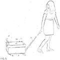
Fig. 1 is an isometric view of a wheeled carton being pulled by a consumer. -
Fig. 2 is a bottom isometric view of the carton, showing the tow strap and handle in stowed position. -
Fig. 3 is a side view in elevation of a carton according to the invention. -
Fig. 4 is a bottom plan view of the carton. -
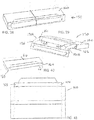
Fig. 5 is an exploded isometric view of a carton with portions broken away for purpose of illustration. -
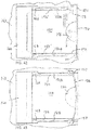
Fig. 6 is an enlarged bottom isometric view of a roller support platform showing the channels and pocket for receiving the tow strap (not shown) and the cutouts and recesses for receiving the rollers (shown in place). -
Fig. 7 is an enlarged fragmentary view in section taken along line 7-7 infigure 4 . -
Fig. 8 is a further enlarged fragmentary bottom isometric view of the roller support platform, showing the channels and pocket for the tow strap, with the tow strap according-folded in the pocket and shown partially withdrawn from the support panel through the channels. -
Fig. 9 is an enlarged fragmentary isometric view of one end of a carton showing the tow strap and handle in stowed position before the strap is withdrawn from the carton for use in pulling the carton along a supporting surface. -
Fig. 10 is an enlarged fragmentary isometric view showing the tow strap and handle partially withdrawn from the carton. -
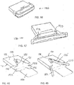
Fig. 11 is a bottom isometric view of an alternate embodiment of roller support platform, wherein a cutout is formed in the underside of the platform for receiving a pre-assembled tow strap cartridge. -
Fig. 12 is an exploded bottom isometric view of the tow strap cartridge for use with the platform offigure 11 . -
Fig. 13 is an exploded top isometric view of the tow strap cartridge for use with the platform offigure 11 . -
Fig. 14 is an exploded fragmentary isometric view showing the relationship between the cutout in the end wall of the carton, the inwardly folded carton end flaps, and the handle and tow strap and the cartridge front plate that covers the cutouts in the end flaps and end wall of the carton. -
Fig. 15 is a bottom isometric view of the roller support platform offigure 11 , with the cartridge offigures 12 and 13 installed. -
Fig. 16 is a top plan view of a dimpled pallet blanket -
Fig. 17 is a top isometric view of a typical wood pallet with the pallet blanket resting on it. -
Fig. 18 is an exploded top isometric view of a carton and a dimpled shelf pad accessory that may be placed on a shelf for use with the carton. -
Fig. 19 is a top plan view of a dimpled carton cover, showing a dimple array that may be provided to enable different stacking arrangements of cartons including cross-stacking. -
Fig. 20 is a bottom isometric view of a modified version of the platform offigure 11 , wherein material is cut away to reduce the weight of the platform. -
Fig. 21 is an enlarged fragmentary view in section of a portion of the wheel assembly in an embodiment of the invention, taken along line 21-21 inFig. 23 . -
Fig. 22 is a top isometric view of the honeycomb platform panel, showing the channels and pockets for receiving the strap loop. -
Fig. 23 is a bottom isometric view of an assembled wheel assembly according to the invention. -
Fig. 24 is an exploded top isometric view of the platform panel and cover pad according to the invention, with a tow strap loop received in the channels and pockets formed in the top surface of the panel. -
Fig. 25 is a top plan view of the platform panel according to the invention. -
Fig. 26A is a side view, shown partially in section, of a first form of roller and support cylinder as used in the invention, wherein the roller comprises a ball. -
Fig. 26B is a front view, shown partially in section, of the roller ball and support cylinder ofFig. 26A . -
Fig. 26C is a plan view looking toward the bottom end of the roller ball and support cylinder ofFig. 26B . -
Figs. 27A - 27C are views similar toFigs. 26A-26C of a second form of roller and support cylinder, wherein the roller comprises a wheel. -
Figs. 28A - 28C are views similar toFigs. 27A-27C of a third form of roller and support cylinder, wherein the roller comprises a wheel with a flanged or stepped axle. -
Fig. 29 is an isometric view of a support cylinder as used in the invention. -
Fig. 30 is a bottom plan view of the support cylinder ofFig. 29 , looking toward the bottom end of the support cylinder. -
Fig. 31 is a side view in elevation of the support cylinder ofFig. 29 . -
Fig. 32 is a side view in elevation of the support cylinder ofFig. 31 , with a roller assembled in place in the cylinder. -
Fig. 33 is an enlarged fragmentary isometric view of a portion of the support platform and tow strap assembly according to the invention, showing a handle attached to the outer end of the tow strap. -
Fig. 34 is a top plan view of a modified wheel assembly platform and attached handle pack, wherein at least one axle on each roller is extended and received in a notch in the platform to orient the roller. -
Fig. 35 is a bottom plan view of one of the roller support cylinders and rollers with extended axle used in the embodiment ofFig. 34 . -
Fig. 36 is a side view in elevation of the support cylinder and roller ofFig. 35 . -
Fig. 37 is a bottom isometric view of the support cylinder and roller ofFigs. 35 and 36 .Fig. 38 is a top isometric view of a first form of handle pack for use in the invention, shown in shipping configuration. -
Fig. 39 is an isometric view of the handle pack ofFig. 38 , with the shipping band removed and the handle partially extended. -
Fig. 40 is an isometric view of the box in which the lanyard is stowed in the handle pack ofFigs. 38 and 39 . -
Fig. 41 is a plan view of the blank used in making the lanyard box ofFig. 40 . -
Fig. 42 is a fragmentary bottom plan view of the handle pack ofFig. 38 installed on a wheel assembly platform, with the forward ends of the lanyard channels in the platform formed as slits and the lanyard extended through these slits. -
Fig. 43 a fragmentary bottom plan view of a slightly modified handle pack ofFig. 38 , wherein the handle is curved and the lanyard channels continue as slots, i.e. are not reduced to slits where they extend through the edge of the platform. -
Fig. 44 is a bottom plan view of a wheel assembly platform with a handle pack assembled to only one end thereof. -
Fig. 45 is a bottom plan view of a variation of the assembly shown inFig. 44 , wherein the handle pack is square rather than elongate and the lanyard channels and lanyards diverge as they extend from the lanyard box through the edge of the platform. -
Fig. 46 is an isometric view of the handle pack ofFig. 45 , shown in its shipping configuration. -
Fig. 47 is an isometric view of the handle pack ofFig. 46 , shown with the shipping band removed and the handle partially extended. -
Fig. 48 is a top isometric view of a lanyard box according to the invention prior to a lanyard being assembled thereto, wherein an empty and open lanyard box is positioned over a winding fork. -
Fig. 49 is a top isometric view of the box offig. 48 , showing a length of lanyard positioned between the prongs of the winding fork preparatory to winding the lanyard. -
Fig. 50 depicts the lanyard being wound into a coil by rotation of the winding fork.Fig. 51 depicts the pack after the lanyard has been wound, the winding fork withdrawn, and the box closed and sealed with opposite legs of the lanyard extending from opposite corners of the box. -
Fig. 52 is a top front isometric view of an embodiment of the invention wherein the tow strap is retractable into the carton. -
Fig., 53 is an isometric view of a spool for use in the retractable lanyard embodiment. -
Fig. 54 is a fragmentary isometric view depicting how the lanyard and torsion spring may be operatively connected with the spool in a preferred embodiment of the invention. -
Fig. 55 is a fragmentary partially exploded top isometric view of the wheel assembly and retractable tow handle of the embodiment shown inFig. 52 . -
Fig. 56 is a top isometric view of the honeycomb platform and retractable tow strap assembled thereto. -
Fig. 57 is a greatly enlarged fragmentary top isometric view of the spool on which the retractable lanyard is wound, and the elastic torsion spring that rotates the spool to retract the lanyard. -
Fig. 58 is a greatly enlarged fragmentary top isometric view showing one end of the elastic spring connected with a mounting structure on the honeycomb platform. -
Fig. 59 is a top isometric view of an alternate embodiment wherein the wheel assembly platform comprises hinged panels constructed to retain a retractable tow strap in place on the platform, with the platform shown from the bottom side and in unfolded position in this figure and a retractable tow strap about to be positioned in cutouts in the platform. -
Fig. 60 is a top isometric view showing the hinged platform offigure 59 after the retractable tow strap has been positioned in the cutouts but before the hinged panels are folded inwardly over the main panel. -
Fig. 61 shows the platform offigure 59 with the hinged half panels being folded inwardly over the main panel. -
Fig. 62 shows the half panels folded inwardly over the main panel into operative position retaining the elastic means in position in their cutouts. -
Fig. 63 is a top isometric view of the fully folded wheel assembly platform offigure 59 .Fig. 64 is a top isometric front end view of the wheel assembly platform offigure 63 , showing the tow strap being extended from the forward end of the platform. -
Fig. 65 is an enlarged fragmentary top isometric view of a spool and retractable tow strap in place in the wheel assembly platform, showing die-cut flaps on the top liner board that are folded down so that when the liner board is placed on top of the honeycomb layer the die-cut flaps hang down in front of the spool and provide surfaces against which the ends of the spool can rotate as the tow strap is extended. -
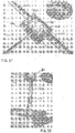
Fig. 66 is a top isometric view of the liner board, showing the die-cut flaps. -
Fig. 67 is a fragmentary exploded view of the honeycomb layer and top liner board being positioned so that the die-cut flaps will extend in front of the ends of the spool. -
Fig. 68 is an enlarged fragmentary top isometric view similar tofigure 65 , showing the tow strap unwound from the spool. -
Fig. 69 is an exploded isometric view of a honeycomb panel and thermoform skin panel that are assembled to form a wheel assembly platform according to another embodiment that is not part of the invention. -
Fig. 70 is a top isometric view of the honeycomb panel and thermoform skin panel assembled together in operative relationship. -
Fig. 71 is a bottom isometric view of the honeycomb panel and thermoform skin panel assembled together in operative relationship. -
Fig. 72 is a fragmentary sectional view taken along line 72-72 infigure 70 , but showing a wheel in operative position on the wheel assembly platform. -
Fig. 73 is a fragmentary sectional view taken along line 73-73 infigure 70 , but showing a wheel in operative position on the wheel assembly platform. -
Fig. 74 is a fragmentary sectional view taken along line 74-74 infigure 70 , but showing a wheel in operative position on the wheel assembly platform. -
Fig. 75 is a fragmentary bottom isometric view of the platform with the thermoformed skin applied to the bottom surface of the honeycomb panel and prior to wheels being mounted to the platform. -
Fig. 76 is a top isometric exploded view of an alternate embodiment wherein hand holes are provided in opposite ends of the carton and a spacer panel with cut outs in its opposite ends is inserted in the carton to provide clearance for fingers inserted through the hand holes so that lifting force can be exerted against the superjacent reams of paper when the carton is lifted by inserting fingers through the hand holes. -
Fig. 77 is a bottom isometric exploded view of the embodiment ofFig. 76 . -
Fig. 78 is an enlarged end view in elevation, with portions shown in section, of a carton having a wheel assembly and tow strap according to any of the forms of the invention, and including the spacer panel and hand holes of the embodiment shown inFigs. 76 and 77 . -
Fig. 79 is a top isometric exploded view of an alternate embodiment wherein the wheel assembly is omitted, the carton is provided with hand holes in its opposite ends, and a spacer panel with cut outs in its opposite ends is inserted in the carton to facilitate lifting of the carton. -
Fig. 80 is a bottom isometric exploded view of the carton ofFig. 79 . -
Fig. 81 is a top isometric view of the carton ofFigs. 79 and 80 shown in its shipping configuration with straps applied around the carton. - Referring more specifically to the drawings, a carton that is not part of the invention is indicated generally at 10 in
figures 1-4 , and is shown infigure 1 as being pulled along a supporting surface by a consumer. The carton in the particular example shown in these figures comprises a substantially standard carton 11 except for the modifications noted below, and has abottom wall 12,opposite side walls opposite end walls figures 1-15 and20 that are not part of the invention,cutouts 20 are formed through thebottom wall 12 of the carton adjacent each corner and in the center thereof, and an opening 21 is formed in one of itsend walls 16 near the bottom edge of the end wall spaced midway between opposite sides of the carton. Further, thecover 17 has either a thickened top wall or, as shown infigure 5 , acover pad 22 is positioned beneath the cover top wall for a purpose described hereinafter. - A
wheel assembly 30 is positioned in the bottom of the carton and a tow strap 31 attached to one end thereof. The wheel assembly comprises aroller support platform 32 adapted to fit within the carton and having a plurality ofcircular cutouts 33 extending through its thickness, and recesses 34 and 35 in its underside extending radially outwardly from diametrically opposite sides of each cutout and formed only partially through the thickness of the platform.Rollers 36 are supported on the support platform. The rollers comprise hardenedspherical paper balls 37 with cylindricalstick paper axles 38 and 39 projecting from diametrically opposite sides thereof. Alternatively, therollers 36 may be made from wood or plastic or other suitable material, with theballs 37 andaxles 38, 39 either formed as one unitary piece or as two pieces assembled together. In the latter instance, the ball could be made with a hole through its center and the axle inserted through the hole so that it projects equally from opposite sides of the ball. In use, the balls are rotatably received inrespective cutouts 33, and the axles projecting therefrom arc rotatably supported inrespective recesses rollers 36 are positioned so that they are in aligned registry with thecutouts 20 in the bottom wall of the carton when the wheel assembly is placed in the carton. By recessing therollers 36 into cutouts and recesses in the support platform the thickness of the wheel assembly is minimized. - As seen best in
figures 6 and8 , a pair of elongate, spaced apart, recessed channels 40 and 41 are formed in the underside of theplatform 32, extending inwardly from one edge thereof and partially through its thickness. The channels terminate at their inner ends at respective opposite sides of a recessed pocket 42 having the same depth as the channels. A loopedtow strap 43 has opposite legs 43A and 43B received in a respective one of the channels 40 and 41, and the inner end of the looped strap is accordion-folded at 44 and stowed in the pocket 42. The spaced apart channels 40, 41 and the pocket 42 form an island 45 that traps the closed inner end of the strap loop and prevents separation of the strap from the support platform. Ahandle 46 is attached to the outer looped end of the strap loop, and as depicted infigures 9 and10 , the handle is shaped and sized to substantially fill and close the opening 21 except for anotch 47 at a top edge of the opening to permit finger access behind one edge of the handle to pull it from the opening when the tow strap and handle are in their stowed position. In this regard, the handle is slightly longer than the opening 21 so that the opposite ends of the handle are engaged snugly in opposite ends of the opening to hold the handle in stowed position as shown infigure 9 until it is desired to withdraw it. - As seen best in
figures 5 and7 , an upperwheel assembly pad 50 is attached to the top side of theroller support platform 32 to provide a smooth wheel assembly upper surface and prevent damage that might otherwise be caused by thecutouts 33 to paper stored in the carton. Theupper pad 50 preferably is made of a water resistant material to prevent penetration of moisture into the carton. A lowerwheel assembly pad 51 is attached to the underside of theplatform 32 to strengthen the bottom of the carton and assist in holding therollers 36 in place in their respective cutouts and recesses. Attachment of thepads - The completed
wheel assembly 30, including thesupport platform 32, upper andlower pads rollers 36, andtow strap 43 with its attachedhandle 46 are glued to the bottom-formingpanel 12 of a flattenedcarton 10, with therollers 36 projecting through thecutouts 20 in thepanel 12. The flats arc then normally shipped to a facility where one wall of the carton is folded up and a stack of reams of cut sheets of paper is slid onto the bottom panel until the stack is stopped by the upwardly folded wall. The remaining walls are then folded upwardly about the stack and suitably secured in place. The lid or cover is then positioned on top of the carton and secured in place with one or more straps. - A plurality of recesses or dimples 55 preferably are formed in the top wall of the
cover 17 in positions to be in registry with the downwardly projectingrollers 36 of a superjacent carton when the cartons are stacked on top of one another. To provide room for the dimples, the top wall of the cover may be thickened, or as shown infigure 5 , acover pad 22 may be placed beneath the top wall of the cover. - As shown in
figures 11-15 , a modified wheel assembly 30' comprises a modified roller support platform 32' and tow strap arrangement. Upper and lowerwheel assembly pads - The cartridge 61 comprises a housing top member 62 having an open
forward end 63, depending side walls 64 and 65 extending along opposite sides thereof, a depending end wall 66 across a rearward end, and a raisedretainer 67 spaced between the side walls and longitudinally offset from the end wall 66. A pocket 68 is defined between the retainer and end wall 66, and the side walls and retainer define a pair of longitudinal channels 69 and 70 extending from the open end of the housing to the pocket. A loopedtow strap 43 is accordion-pleated and placed in the pocket, with the legs 43A and 43B thereof extending through a respective channel and through the open forward end. Ahandle 46 preferably is attached to the outer end of the looped strap. Tabs 71A and 71B project laterally outwardly from opposite sides of the rearward end of the housing 62, and when the cartridge is in operative position in the platform 32' as shown infigure 15 these tabs are received in notches 60A and 60B. The tabs 71A and 71B, in cooperation with the lowerwheel assembly pad 51, retain the cartridge in the recess 60. A cover 72 is assembled to the housing top member 62 in overlying relationship to the channels and pocket to retain the tow strap in the pocket and channels but enable withdrawal of the strap legs 43A and 43B through the channels. The raisedretainer 67 and cover 72 cooperate to trap the rearward end of the looped tow strap behind the retainer so that it cannot be withdrawn completely from the cartridge housing. A forward end wall 73 on the cartridge housing forms a cover plate that is shaped and sized to cover the cutout 21 in thecarton end wall 16 and the cutouts 74 and 75 in the lower adjacent edges of the carton end flaps 76 and 77, as indicated by the dot-and-dash lines infigure 14 , protecting the interior of the carton against ingress of dirt, moisture, and the like through the cutouts.Notches - The cartridge housing, including the cover 72 and end wall 73, may be made of plastic or paper or other suitable material, although an easily recyclable material such as paper is preferred.
- A pallet blanket accessory 80 having a plurality of dimples 81 in its upper surface may be provided for placement on a pallet P as shown in
figures 15 and16 to prevent damage to the rollers in the bottom cartons stacked on a pallet. When the pallet blanket is used, the rollers of the bottom cartons on the pallet are received in the dimples of the blanket, permitting the bottoms of the cartons adjacent the pallet to rest on the blanket. - Similarly, to enable stable positioning of a carton according to the invention on a shelf S, a shelf pad accessory 90 having a plurality of dimples 91 in its upper surface may be provided as shown in
figure 17 . Use of the shelf pad prevents unwanted rolling of the carton on the shelf. - In order to enable different stacking configurations of cartons according to the invention, including cross-stacking, the dimples in the upper surface of the carton cover have to be arranged in a particular pattern. One such arrangement is shown at 100 in
figure 18 . -
Figure 20 shows a modified roller support platform 81.28 cm (32"), wherein areas are cut away at 101 to reduce weight. The particular size and arrangement of cut away areas shown is one example of how weight savings can be accomplished, but it should be understood that other suitable arrangements may be utilized. - In a specific construction of a carton according to the first embodiment of the invention, the
roller balls 37 preferably have a diameter of from about 0.635 cm to about 3.175 cm (about 3/4 inch to about 11/4 inches), theaxles 38 and 39 each have a diameter of about 0.635 cm (1/4 inch) and a length of about 2.54 cm (1 inch), and the upper and lowerwheel assembly pads roller support platform 32 each have a thickness of about 0.079 cm (1/32 of an inch). The combined thickness of theroller support platform 32 or 32' and upper andlower platform pads upper pad 50 on the roller support platform. - A wheel assembly according to the invention is referenced generally at 100 in
figures 21-33 . In this form of the invention rollers 101 are mounted in and supported by short rigidroller support cylinders 102 glued incutouts 103 extended through aroller support platform 104 at opposite side edges of the platform and spaced slightly inwardly from opposite ends thereof. A roller 101 and itssupport cylinder 102 are also mounted in acenter cutout 105 in the middle of the platform. As seen infigure 21 , the opposite ends of the support cylinders terminate at the top and bottom surfaces of the platform and the rollers are mounted so that they project from the bottom ends of the cylinders and downwardly past the bottom of the platform. As shown in this figure, the wheel assembly is mounted inside a carton above thebottom wall 12, although if desired it could be mounted to the bottom wall outside the carton. If mounted inside the carton, as shown, thebottom wall 12 hascutouts 20 therethrough in alignment with the rollers, as in the previous embodiment (see
Fig. 2 ) so that the rollers extend through the cutouts to support the bottom of the carton above a surface S. - Undercut
notches 106 are formed in the bottom ends of the support cylinders on diametrically opposite sides thereof, andshort axles - The rollers may have any suitable form, such as the balls 101A shown in
figures 26A-26C , wheels 101B as shown infigures 27A-27C , orwheels 101C with flanged or stepped axles 107', 108' as shown infigures 28A-28C . - The
support platform 104 is made of corrugated material having a honeycomb core with heavy duty liners. One suitable material is Hexacomb® D/C, core type 1, with heavy facings, available from Prcgis Corporation of Lake Forest, Illinois. -
Channels 110 and 111 are formed in the top surface of theplatform 104, extending longitudinally thereof through opposite ends of the platform and on opposite sides of thecenter cutout 105. The channels may be formed in any suitable manner, as by crushing or cutting.Pockets - A double
tow strap arrangement 120 is provided in the particular example shown, although it should be understood that any of the single tow strap arrangements described in connection with the previous embodiments could be used if desired. The double tow strap comprises a singlecontinuous loop 121 with opposite legs 121A, 121B of the loop received in arespective channel 110 or 111. The loop is substantially longer than thesupport platform 104, and the central portions of the legs are accordion-folded and stowed in arespective pocket figure 24 . Handlepads 122 may be provided on the outer ends of the tow straps, as shown infigures 24 and33 . Although the outer ends of the tow straps and the associated handle pads are shown spaced from the respective opposite ends of theplatform 104 infigures 24 and33 , the handle pads are normally stowed inshallow recesses 123 in respective opposite ends of the support platform so that the handle pads are substantially flush with the ends of the platform.Barbs 124 on the back or inside surface of the handle pads are inserted into the core of the support platform to hold the handles in place until it is desired to use them to pull the carton along a surface. - When the
wheel assembly 100 is mounted inside the carton as depicted infigure 21 , it will be necessary to provide cutouts in a bottom portion of those walls adjacent the outer ends of the tow straps to enable access to the tow straps, as in the previous embodiments. - As seen in
figure 21 , a support platform cover sheet orpad 130 is glued to the top surface of theplatform 104 in covering relationship to the cutouts and tow strap to prevent damage to paper (not shown) stored in the carton and to hold the tow strap in the channels and pockets. The platform is supported immediately on top of thebottom wall 12 of the carton. Generally U-shaped cuts 131 are made in the platform, forming bendable flaps 132 in positions to be in registry with thepockets - In a specific construction of this form of the invention, the
channels 110, 111 andpockets notches 106 of approximately 0.635 cm (0.25 inch) depth will result in the roller ball or wheel projecting below the bottom the carton sufficiently to provide a floor clearance of about 0.313 cm (5/16 inch). - In this double tow strap arrangement, only one tow strap can be pulled from one end or the other of the carton and used to pull the carton along a surface. If desired, both tow straps can be pulled from the carton and wrapped upwardly around the carton for use as a handle or handles to lift the carton.
- An alternate embodiment of wheel assembly and tow strap is indicated generally at 140 in
Figs. 34-41 . In this form of the invention at least one of the axles 141 is elongated and extends past the outer diameter of theroller support cylinder 102. The extended axle is received in anadjacent notch 142 in thesupport platform 143 and serves to properly orient the roller. In the particular example shown, only one of the axles is extended in those rollers positioned along the sides of the platform, but both axles can be extended in the center roller andnotches 142A and 142B provided on opposite sides of theopening 144 for receiving the center roller and its support cylinder (not shown). - Also, in the
Fig. 34 embodiment ahandle pack 150 is provided at only one end of the wheel assembly platform. Thehandle pack 150 is elongated and the legs 151A, 151B of the tow strap 151 extend in parallel relationship to one another throughparallel channels 152, 153 in the platform. A land orisland 154 is formed between thechannels 152, 153 and therecess 155 for receiving the handle pack. The outer edge of the island is convexly curved and has asemi-circular recess 156 formed in its center. Anotch 157 is formed in the outer wall of each channel near its outer end. Thehandle 158 is curved to lie against the curved edge of the island and the opposite ends of the handle are engaged in thenotches 157 to hold the handle in its stowed position. - As seen best in
Figs. 38-41 , thehandle pack 150 comprises arectangular box 160 preferably formed of paperboard. Thetow strap 150 is appropriately folded and stowed in this box, with the opposite legs 151A and 151B thereof extended throughopenings 161, 162 in opposite ends of the forward edge of the box.Small flaps openings 161, 162 serve to guide the legs of the tow strap as it enters thechannels 152, 153 and prevent snagging of the strap as it is pulled from the box and outwardly through the channels. SeeFigs. 42 and 43 . -
Fig. 42 shows an alternate arrangement wherein thehandle 170 is straight and is nested in arecess 171 in the edge of the platform so that the handle is substantially flush with the outside of the carton when it is in its stowed position. Inadvertent displacement of the handle from the recess is prevented by narrowing the outer ends of the channels 152', 153' toslits 172 which frictionally engage the legs of the tow strap to retain it in position until it is deliberately withdrawn for use. When it is desired to withdraw the tow strap, the center of the handle can be pushed into thearcuate recess 156, which causes the opposite ends of the handle to flex outwardly where they can be accessed. -
Fig. 43 is an enlargement of the tow strap arrangement shown inFig. 34 . -
Fig. 44 shows a variation of the tow strap arrangement ofFig. 44 , but wherein the channels 152", 153" have a constant width throughout their length and the outer ends are not reduced to slits as in the previous embodiment. In this embodiment, thehandle 170 is frictionally received in the recess 171' to retain it in stowed position until it is desired to withdraw it. Also, this embodiment shows the platform withoutnotches 142 for receiving an extended axle on the roller, and could be used with a roller assembly as shown inFigs. 26A-28C , for example. -
Figs. 45-47 depict a variation of theFig. 44 embodiment, wherein the handle pack 180 is square rather than elongated as in theFig. 44 embodiment, and the channels 181, 182 for receiving the legs 151A, 151B of the tow strap diverge outwardly through the adjacent edge of the platform. The handle pack 180 is shown in its shipping configuration inFig. 46 , and with the shipping band removed and the handle partially extended inFig. 47 . -
Figs. 48-51 depict one way in which the tow strap 150' can be wound or coiled in thehandle pack box 190. As shown inFig. 48 , a bottom wall 191 of the box has ahole 192 substantially in the center thereof, and thetop wall 193 has a trapezoidally shapedcutout 194 therein, extending at its open end through the forward edge of thewall 193 and at its closed inner end to just past thehole 192 in the bottom wall. Aflange 195 of narrower width than the bottom wall is foldably joined to the forward edge of the bottom wall, and aclosure flap 196 is foldably joined to that edge of the flange opposite its folded connection with the bottom wall.Small flaps 197A, 197B are foldably joined to opposite ends of theflange 195. In use, thehole 192 of the open box is positioned over a windingfork 198 and the tow strap is placed between the tines of the fork. The fork is then rotated to wind the tow strap into a coil, and the legs 151A, 151B of the strap are positioned to extend through the corners of the open end of the box. The winding fork is then withdrawn and theclosure flap 196 is closed and sealed. - An embodiment with a retractable lanyard is indicated generally at 200 in
Figs. 52-58 . In this form of the invention the lanyard comprises a single length of cord orrope 201 wound around aspool 202 that is connected with atorsion spring 203. Mechanical energy is stored in the torsion spring when the lanyard is pulled to unwind it from the spool, and upon release of the lanyard the torsion spring rotates the spool to rewind the lanyard on it. The retractable lanyard is mounted to aplatform 204 that in a preferred embodiment comprises the Hexacomb® material previously described. - Thus, with particular reference to
Figs. 56-58 , atransverse slot 205 is made in the top surface of theplatform 204, with anenlarged cutout 206 at the midportion of the slot. One end edge of the platform has arecess 207 formed therein, and alongitudinal slot 208 extends from thecutout 206 to a midportion of therecess 207. Opposite side edges of the platform are cut to form outwardly protruding stubs or pegs 209A and 209B, respectively. - As seen best in
Figs. 53 ,54 ,57 and 58 , thespool 202 comprises acentral shaft 210 with radially enlargedhubs 211A and 211B on opposite ends. Acentral bore 212 extends axially through the spool from one end through the other, andsmall holes 213A, 213B and 214A, 214B are formed through the base of the respective hubs on diametrically opposite sides thereof closely adjacent the outer diameter of theshaft 210. In the particular example shown, thetorsion spring 203 comprises a rubber band. The rubber band is passed through thebore 212 so that loops 212A, 212B project from respective opposite ends of the spool. One end of thecord 201 is then passed outwardly through the hole 213A, through the adjacent loop 212A of the rubber band, back through the other hole 213B and across to the other end of the spool where the cord is passed outwardly throughhole 214A, through the adjacent loop 212B, and back through the other hole 214B. The end is then knotted to prevent it from being retracted back through the respective holes. - In use, the spool is placed in the
cutout 206, with the loops 212A and 212B of the rubber band lying in theslot 205 and thecord 210 lying in theslot 208. Outer ends of the loops 212A and 212B of the rubber band are then placed over respective stubs or pegs 208 and 209, and the cord is wound onto the spool so that the handle 215 attached to its outer end lies in therecess 207 in the edge of the platform. Preferably, the torsion spring is at least partially twisted to pre-load it when thecord 201 is fully wound on the spool. - In the retractable embodiment of
Figs. 52-58 , the tow strap or lanyard is automatically retracted to a stowed position when not in use. - A further embodiment is shown in
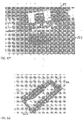
figures 59-64 , wherein the wheel assembly platform 250 comprises amain panel 251 andhalf panels wheel receiving opening 255 is made in the center of themain panel 251, adjacent the enlarged area 206', and oval shapedopenings 256 are made across the hinged connection between the main panel and the half panels adjacent opposite ends of the half panels. - A
semi-circular cutout 257 is made in the outer edge of each half panel midway along its length, and rectangular notches orcutouts 258 are made adjacent thecutouts 257. When the half panels are folded inwardly over the main panel thesemi-circular cutouts 257 are in aligned registry with thewheel opening 255, and therectangular cutouts 258 are in aligned registry with the enlarged area 206'. - A portion of the outer edge of each half panel is cut away to define a recessed
edge 259 leading from eachrectangular cutout 258 to the forward end of the respective half panel and the end of each recessed edge adjacent arespective cutout 258 is angled at 260. When the half panels are folded inwardly over the main panel as shown infigure 62 , the recessed edges define a channel 261 leading from the enlarged area 206' to the forward edge of the platform, with theangled portions 260 defining a tapered lead-in area from the enlarged area to the channel 261. A forward edge of the main panel is recessed at 207 in alignment with the enlarged area 206' and the channel 261. - A
retractable lanyard 201 wound on aspool 202 torsionally biased by elastic members 212A and 212B as in the previous embodiment is assembled to the wheel assembly platform 250. Pins 262 are attached to the outer ends of the elastic members, and a handle 215 is attached to the outer end of thelanyard 201. The retractable lanyard is assembled to the platform by placing thespool 202 in the central enlarged area 206', stretching the elastic members outwardly and placing the pins 262 in the slots 254A and 254B, and pulling the lanyard forwardly and placing the handle 215 in therecess 207. The half panels are then folded inwardly to retain the elastic members, pins, and handle in their respective positions. -
Figures 65-68 depict a preferred construction in which flaps 270 are die-cut from thetop liner board 271 of the wheel assembly platform and folded downwardly in front of theends 211A and 211B of the spool to provide surfaces against which the ends of the spool can rotate when the tow strap is being withdrawn to prevent the ends of the spool from digging into thehoneycomb layer 273. - Another embodiment that is not part of the invention is indicated generally at 280 in
figures 69-75 . In this embodiment a thermoformedplastic skin 281 is applied to the underside of thehoneycomb panel 282. As in previous embodiments, thepanel 282 hascutouts 33 for receivingrollers 37 andcutouts cutouts 33 for receivingaxles 38 and 39 on the rollers. See, e.g.,figure 6 . Thethermoformed skin 281 is shaped withsemi-spherical domes 283 that project into thecutouts 33, andsemi-cylindrical extensions 284 that fit into thecutouts figures 72-75 ,notches 285A and 285B are cut into the skin in aligned registry with thecutouts opening 286 leading from the bottom of the skin into the respective notches is narrower than the diameter of theaxles 38 and 39, whereby when aroller 37 is assembled to the platform as shown infigures 73 and 74 , the axles are frictionally retained in the notches. - In addition to serving to hold the rollers assembled to the platform, the
skin 281 protects the platform and the contents of the container from water when the container is placed on a wet surface. - Instead of laminating a skin to a honeycomb panel, the skin may be made thicker to accommodate the wheel assemblies and the honeycomb panel omitted (not shown).
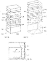
- Yet another embodiment of the invention is shown in
Figs. 76-78 , wherein thecarton 300 hashand holes spacer panel 303 is inserted in the carton between the layers of reams ofpaper 304. Arecess 305 is formed in cach end of thepanel 303 and the panel is positioned so that these recesses are in registry with the hand holes 301, 302. The recesses provide access for inserting the fingers through the hand holes so that lifting force can be exerted against the superjacent reams of paper to lift the carton. Thepanel 303 can comprise a sheet of honeycomb material or other material to provide the necessary space for inserting the fingers. -
Figs. 79-81 depict an embodiment that is not part of the invention wherein the wheel assembly of the previous embodiments is omitted. This form of the invention provides a carton withhand holes panel insert 303 withrecesses 305 in its opposite ends to provide space for inserting the fingers through the hand holes to facilitate lifting the carton. When the carton contains reams ofpaper 304, the spacer panel provides space for inserting the fingers between the reams of paper so that lifting force can be exerted against superjacent reams to lift the carton. Tie straps S may be placed longitudinally and/or transversely around the carton, as shown in broken lines inFig. 81 . - As used herein, the term "roller" or "rollers" is intended to encompass wheels or other devices that support an object for rolling movement on a surface.
- While particular embodiments of the invention have been illustrated and described in detail herein, it should be understood that various changes and modifications may be made in the invention without departing from the scope of the invention as defined by the appended claims.
Claims (12)
- A carton for cut sheets of paper, wherein said carton comprises: a bottom wall (12, 191), opposite side walls (13, 14), and opposite end walls (15, 16);
a wheel assembly (30, 30') mounted to said carton bottom wall (12, 191), said wheel assembly (30, 30') including a roller support platform (32, 32') and a plurality of roller means projecting downwardly from said carton bottom wall (12, 191) to support said carton above a supporting surface and enable said carton to be easily moved along said supporting surface on said rollers;
said carton bottom wall (12, 191) comprises said carton bottom wall (12,191) having a plurality of cutouts (20) therein;
said rollers project downwardly through said cutouts (20) in said carton bottom wall (12, 191);
said wheel assembly is above said carton bottom wall (12, 191);
characterized in that
at least one tow strap (31, 43) connected to said carton to enable a person to pull said carton along said supporting surface, said at least one tow strap (31, 43) having a stowed position in said carton and an extended position with one end of said at least one tow strap extended outside said carton, wherein
said platform has recess means formed in one surface thereof and said at least one tow strap (41, 43) is received in that recess means and attached at an inner end thereof to that platform;
and said roller support platform (32, 32') is positioned on top of said carton bottom wall (12, 191), said roller support platform (32, 32') having cutouts (20) in which said rollers are received and supported;
said cutouts (20) in said roller support platform (32, 32') extend through said roller support platform (32, 32') from a top surface through a bottom surface thereof; short, rigid, roller support cylinders are glued in said cutouts (20) in said roller support platform (32, 32'), said roller support cylinders having an upper end substantially flush with said top surface of said roller support platform (32, 32'), and a lower end substantially flush with said lower surface of said roller support platform (32, 32');
said rollers are mounted in and supported by said roller support cylinders;
two notches (106) are formed in said lower end of each said roller support cylinder, said notches being disposed on diametrically opposite sides of respective ones of said roller support cylinders; and
an axle projects from each of two diametrically opposite sides of each said roller, said axles being rotatably supported in respective said notches. - The carton according to claim 1 for cut sheets of paper, wherein said notches (106) are undercut to hold said axles in place in said notches during handling of said wheel assembly (30, 30').
- The carton according to claim 1 for cut sheets of paper, wherein said rollers comprise spherical balls.
- The carton according to claim 1 for cut sheets of paper, wherein said rollers comprise wheels.
- The carton of one of claims 1 to 4, wherein said roller support platform (32, 32') comprises a panel of honeycomb material with a thermoformed skin applied to its underside.
- The carton of one of claims 1 to 4, wherein all components of said carton except for said at least one tow strap (31, 43) are made of paper material and can be single streamed into an old corrugated container (OCC) reclamation process.
- The carton of one of claims 1 to 4, wherein said roller support platform (32, 32') is made of corrugated material having a honeycomb core with heavy duty liners.
- The carton of one of claims 1 to 4, wherein said roller support platform (32, 32') comprises areas that are cut away to reduce weight.
- The carton of one of claims 1 to 4, further comprising hand holes in said opposite end walls (15, 16) through which fingers may be inserted for lifting said carton; and a spacer panel inserted in said carton between layers of said cut sheets of paper, said spacer panel having a recess in each end thereof in registry with said hand holes to provide space for inserting said fingers between said cut sheets of paper to facilitate lifting said carton.
- The carton one of claims 1 to 4, wherein an upper wheel assembly pad (50) is attached on top of said roller support platform (32, 32') to provide said wheel assembly (30, 30') with a smooth upper surface, said upper wheel assembly (30, 30') pad being made of a water resistant material to prevent penetration of moisture into said carton.
- The carton of one of claims 1 to 4, wherein
said recess means comprises an enlarged pocket in which said at least one tow strap (31, 43) is folded and stored, and at least one channel extending from said enlarged pocket and opening through one edge of said roller support platform (32, 32'), an end of said at least one tow strap (31, 43) leading from said enlarged pocket and through said channel to outside said carton. - The carton according to claim 11, wherein
said recess means comprises an enlarged pocket in which said at least one tow strap (31, 43) is folded and stored, and at least one channel extending from said enlarged pocket and opening through one edge of said roller support platform (32, 32'), an end of said at least one tow strap leading from said enlarged pocket and through said channel to outside said carton; said at least one tow strap (31, 43) comprises a single tow strap formed as a closed loop, one closed end of said closed loop being received in said enlarged pocket and another end of said closed loop being outside said carton;
said at least one channel comprises two spaced apart channels (40, 41); and
said two spaced apart channels (40, 41) and said enlarged pocket define a raised island that engages said one closed end of said closed loop to prevent withdrawal of said closed loop from said enlarged pocket.
Priority Applications (1)
| Application Number | Priority Date | Filing Date | Title |
|---|---|---|---|
| PL15201157T PL3059179T3 (en) | 2012-02-16 | 2013-02-15 | Box with a wheel assembly and a tow strap |
Applications Claiming Priority (4)
| Application Number | Priority Date | Filing Date | Title |
|---|---|---|---|
| US201261599600P | 2012-02-16 | 2012-02-16 | |
| US201261724457P | 2012-11-09 | 2012-11-09 | |
| PCT/US2013/026383 WO2013123352A2 (en) | 2012-02-16 | 2013-02-15 | Box with a wheel assembly and a tow strap |
| EP13708955.3A EP2814747B1 (en) | 2012-02-16 | 2013-02-15 | Box with a wheel assembly and a tow strap |
Related Parent Applications (2)
| Application Number | Title | Priority Date | Filing Date |
|---|---|---|---|
| EP13708955.3A Division-Into EP2814747B1 (en) | 2012-02-16 | 2013-02-15 | Box with a wheel assembly and a tow strap |
| EP13708955.3A Division EP2814747B1 (en) | 2012-02-16 | 2013-02-15 | Box with a wheel assembly and a tow strap |
Publications (2)
| Publication Number | Publication Date |
|---|---|
| EP3059179A1 EP3059179A1 (en) | 2016-08-24 |
| EP3059179B1 true EP3059179B1 (en) | 2018-08-01 |
Family
ID=47843401
Family Applications (3)
| Application Number | Title | Priority Date | Filing Date |
|---|---|---|---|
| EP15201157.3A Active EP3059179B1 (en) | 2012-02-16 | 2013-02-15 | Box with a wheel assembly and a tow strap |
| EP13708955.3A Active EP2814747B1 (en) | 2012-02-16 | 2013-02-15 | Box with a wheel assembly and a tow strap |
| EP13708284.8A Active EP2814743B1 (en) | 2012-02-16 | 2013-02-15 | Carton box with hand holes and spacer panel to facilitate lifting and carrying the box |
Family Applications After (2)
| Application Number | Title | Priority Date | Filing Date |
|---|---|---|---|
| EP13708955.3A Active EP2814747B1 (en) | 2012-02-16 | 2013-02-15 | Box with a wheel assembly and a tow strap |
| EP13708284.8A Active EP2814743B1 (en) | 2012-02-16 | 2013-02-15 | Carton box with hand holes and spacer panel to facilitate lifting and carrying the box |
Country Status (11)
| Country | Link |
|---|---|
| US (3) | US20130313136A1 (en) |
| EP (3) | EP3059179B1 (en) |
| CN (2) | CN104114451B (en) |
| BR (3) | BR122020000763B1 (en) |
| CA (3) | CA2915489C (en) |
| ES (1) | ES2582903T3 (en) |
| IN (2) | IN2014DN06818A (en) |
| MX (3) | MX350796B (en) |
| PL (3) | PL3059179T3 (en) |
| RU (2) | RU2584518C2 (en) |
| WO (2) | WO2013123352A2 (en) |
Families Citing this family (13)
| Publication number | Priority date | Publication date | Assignee | Title |
|---|---|---|---|---|
| PL3059179T3 (en) | 2012-02-16 | 2019-04-30 | Int Paper Co | Box with a wheel assembly and a tow strap |
| MX2016005104A (en) * | 2013-10-21 | 2016-07-19 | Int Paper Co | Box with carry handles. |
| CN104997263A (en) * | 2015-07-29 | 2015-10-28 | 胡世棉 | Storage box |
| EP3193310B1 (en) * | 2016-01-15 | 2019-11-20 | Neopost Technologies | Franking machine with integrated scale |
| CN106005662B (en) * | 2016-06-16 | 2019-01-11 | 铜陵锋帆彩色印务有限公司 | Reinforced cartons |
| CN106828560A (en) * | 2016-12-05 | 2017-06-13 | 怀宁县鑫华制衣有限公司 | A kind of dress transportation box |
| TWM550248U (en) * | 2017-06-08 | 2017-10-11 | Chen-Huang Xie | Storage car for foldaway table and chair |
| CN108608677B (en) * | 2018-04-04 | 2019-11-22 | 江苏南江智能装备股份有限公司 | A kind of environment-friendly type paper handle process equipment |
| CN109178610A (en) * | 2018-10-29 | 2019-01-11 | 郑州莱兹电子科技有限公司 | A kind of Electron product packaging case of moisture-proof antidetonation |
| US11440284B2 (en) | 2018-11-21 | 2022-09-13 | Star Board Materials, LLC | Paperboard panel and method of making same |
| DK3670292T3 (en) * | 2018-12-19 | 2021-04-12 | Hilko Koch | SYSTEM FOR TRANSPORT, HANDLING AND / OR STORAGE OF GOODS |
| US11629520B1 (en) * | 2019-04-05 | 2023-04-18 | Edward Geraghty | Movable decorative base assembly selectively attachable to a parasol or umbrella |
| CN111252124A (en) * | 2020-03-04 | 2020-06-09 | 吉林工程技术师范学院 | Multi-functional containing box for financial accounting |
Family Cites Families (96)
| Publication number | Priority date | Publication date | Assignee | Title |
|---|---|---|---|---|
| AT8447B (en) | 1901-11-29 | 1902-07-25 | Karl Grimm | Uniform cravatte. |
| US1199790A (en) | 1914-11-12 | 1916-10-03 | Hunter Smith J | Tennis-court-tape reel. |
| US1647581A (en) * | 1926-08-04 | 1927-11-01 | Atlas Box Company | Fiber-board package |
| GB372119A (en) * | 1931-05-28 | 1932-05-05 | Eburite Corrugated Containers | Improvements in cardboard or like containers for articles of merchandise |
| US2257977A (en) * | 1937-06-21 | 1941-10-07 | Charles F Richard | Carton structure |
| US2284385A (en) * | 1940-10-28 | 1942-05-26 | Schlitz Brewing Co J | Carton |
| US2716558A (en) | 1953-12-28 | 1955-08-30 | Anna K Sullivan | Article carrying and rolling-transport device |
| US2805077A (en) | 1954-11-17 | 1957-09-03 | Katz Milton | Removable portable rollers for luggage |
| US2942771A (en) | 1957-12-03 | 1960-06-28 | Chicago Printed String Company | Article support |
| US2961143A (en) * | 1958-04-23 | 1960-11-22 | Mead Packaging Inc | Tray structure for bottles and other articles |
| US3042461A (en) | 1958-11-20 | 1962-07-03 | Signal Mfg Co | Dolly for cleaning apparatus with improved wheel bearings |
| US3086690A (en) * | 1961-01-09 | 1963-04-23 | Dan H Beck | Partitioned carton |
| US3135527A (en) | 1961-07-28 | 1964-06-02 | Philip B Knapp | Wheeled market carts |
| US3157342A (en) | 1963-01-07 | 1964-11-17 | Morton Salt Co | Carton |
| US3198300A (en) * | 1963-05-31 | 1965-08-03 | George K Tuttle | Handle having a retractable strap |
| US3337285A (en) | 1963-09-19 | 1967-08-22 | Signal Stat Corp | Vehicle rear view mirror with convex mirror portion |
| US3302955A (en) | 1965-04-29 | 1967-02-07 | Budd Co | Spacesaver swivel castered roving can |
| US3487479A (en) * | 1968-02-27 | 1970-01-06 | Percy E Grooms | Combination travel crib assembly |
| DE1755130B1 (en) | 1968-04-02 | 1970-09-24 | Jost Werke Gmbh | Rotary bolt arrangement for securing a container |
| US3492016A (en) | 1968-04-18 | 1970-01-27 | Dennis J O Connor | Wheeled vehicle |
| US3438480A (en) | 1968-05-03 | 1969-04-15 | Paul L Chabrelot | Wig carrying case |
| US3653577A (en) | 1970-06-15 | 1972-04-04 | Bernice Irene Wyner | Cake cover |
| US3680810A (en) | 1971-02-16 | 1972-08-01 | Saxton Products Inc | Pay-out container for spooled wire and analogous elongated elements |
| US3794239A (en) | 1972-04-24 | 1974-02-26 | Alton Box Board Co | Convenience handle means for carton |
| US3853285A (en) | 1973-03-03 | 1974-12-10 | H Woodring | Retractable cable device |
| US3954226A (en) | 1974-04-08 | 1976-05-04 | Pickering Phillip A | Strap coiling mechanism |
| GB1480726A (en) | 1974-07-01 | 1977-07-20 | Ross & Bonnyman Eng Ltd | Load containers |
| US4060252A (en) | 1974-11-06 | 1977-11-29 | Geoffrey John Mowery | Ball type transfer apparatus |
| US3982613A (en) | 1975-08-07 | 1976-09-28 | Leeds Travelwear, A Division Of Rapid-American Corporation | Retractable pull strap on wheeled luggage |
| US4068779A (en) * | 1975-12-01 | 1978-01-17 | Canfield Michael P | Foamed plastic cooler and handle combination |
| US4032009A (en) | 1976-02-11 | 1977-06-28 | Robert E. Taylor | Container system for garage door opener |
| US4058250A (en) * | 1976-05-04 | 1977-11-15 | Domtar Limited | Reinforced side carry carton |
| FR2380949A1 (en) | 1977-02-22 | 1978-09-15 | Colgate Palmolive Co | METHOD FOR ATTACHING A HANDLE TO A PACKAGING AND RESULTING PACKAGING |
| DE2733390A1 (en) | 1977-07-23 | 1979-02-08 | Color Druck Baiersbronn Wilhel | Folded box with handle - has central support flap with handle slot on opposite wall to closing flap |
| US4128253A (en) | 1977-10-14 | 1978-12-05 | Powers Richard J | Pallet and roller post construction therefor |
| EP0009921B1 (en) | 1978-10-05 | 1983-01-26 | Garnet Marshall Underwood Hannan | Wheel means for container handling |
| US4286714A (en) | 1979-10-19 | 1981-09-01 | Champion International Corporation | Sleeve with pre-applied handle for setup box or folding carton |
| US4311288A (en) | 1980-11-24 | 1982-01-19 | Jerry H. Webster | Strap winding mechanism |
| FR2501635A1 (en) | 1981-03-13 | 1982-09-17 | Socar | Hand grip for package - has flexible strip sewn or glued to package sheets and housed in cut out |
| US4408710A (en) * | 1981-06-12 | 1983-10-11 | Owens-Illinois, Inc. | Carton having tear resistant hand holes |
| US4416429A (en) | 1981-06-29 | 1983-11-22 | Jessamine Donald W | Water ski tow rope reel apparatus |
| US4583681A (en) | 1984-09-10 | 1986-04-22 | Purex Corporation | Extensible handle carton with leakage preventing flap structure |
| US4772035A (en) | 1987-05-19 | 1988-09-20 | Jeffrey Danial | Wheeled carrier for packages |
| US4969610A (en) | 1988-12-12 | 1990-11-13 | Jerry Taylor | Rope rewinding device for a ski boat |
| US4940252A (en) | 1989-04-13 | 1990-07-10 | Grumman Aerospace Corporation | Removable container caster assembly with tow capability |
| US5284247A (en) | 1989-07-12 | 1994-02-08 | Saf-T Corporation | Structural utility strap carton and dispenser |
| EP0410772A3 (en) | 1989-07-28 | 1991-04-24 | Jan Cornel Engelbrecht | Trolley |
| IT1239843B (en) | 1990-03-06 | 1993-11-15 | Olimpio Stocchiero | LID WITH HANDLE FOR ACCUMULATOR CONTAINERS |
| SE468942B (en) | 1990-09-05 | 1993-04-19 | Bjoern Jondelius | DEVICE FOR PREPARING PRINTER PAPER |
| CH683089A5 (en) * | 1991-06-19 | 1994-01-14 | Oscar Roth | The set of parts for producing a package. |
| US5106015A (en) | 1991-07-15 | 1992-04-21 | American Colloid Company | Container |
| US5467915A (en) | 1992-10-21 | 1995-11-21 | Roberts Systems, Inc. | Lift-up handle |
| WO1994019642A1 (en) | 1993-02-26 | 1994-09-01 | Dyment Limited | Promotional portable display stand |
| US5316210A (en) * | 1993-05-14 | 1994-05-31 | Georgia-Pacific Corporation | Paperboard storage container |
| US5445396A (en) | 1993-08-09 | 1995-08-29 | Gale Group, Inc. | Nestable dolly construction |
| US5419009A (en) | 1993-10-29 | 1995-05-30 | Assis; Rony | Packaging handle |
| US5564805A (en) | 1994-01-03 | 1996-10-15 | Contico International, Inc. | Storage container with wheels |
| US5372899A (en) * | 1994-03-16 | 1994-12-13 | At&T Corp. | Battery handle |
| US5403023A (en) | 1994-07-29 | 1995-04-04 | Tsai; Cheng-Hsien | Luggage truck |
| US5551715A (en) * | 1994-11-30 | 1996-09-03 | Pickard; Albert | Two position utility basket |
| CN1060122C (en) | 1995-01-09 | 2001-01-03 | 纳迪恩·辛诺 | Dolly and box for use with the dolly |
| GB2301768B (en) | 1995-06-08 | 1999-03-10 | Outrigger Inc | Auxiliary luggage holder |
| FR2741852A1 (en) | 1995-11-30 | 1997-06-06 | Czechowski Jean | Cardboard trolley with rollers |
| US5898472A (en) | 1997-07-08 | 1999-04-27 | Oshikawa; Hidetoshi | Automatic eyewear strap winding device |
| JPH1159666A (en) * | 1997-08-18 | 1999-03-02 | Rengo Co Ltd | Packaging case made of corrugated cardboard |
| US6244502B1 (en) * | 1999-07-29 | 2001-06-12 | Weyerhaeuser Company | Self-dividing box, components thereof, and method of manufacturing, assembly and disassembling the same |
| US20010038778A1 (en) | 2000-05-04 | 2001-11-08 | Tatina Richard A. | Winch assembly with web strap storage |
| DE20202320U1 (en) * | 2002-02-14 | 2002-05-29 | Urban Marion | Carrier for a plurality of containers, e.g. beverage bottles |
| FI5430U1 (en) * | 2002-04-05 | 2002-07-17 | Hartwall K Oy Ab | Box |
| US6979005B1 (en) | 2002-06-17 | 2005-12-27 | Chriscott Supply, Inc. | Stackable dollies and dolly systems |
| GB2390082A (en) | 2002-06-27 | 2003-12-31 | Graham Carrier | Collapsible container on wheels |
| US6983946B2 (en) | 2003-04-01 | 2006-01-10 | Porta Plastic Products | Transportable containers apparatus and method |
| DE502004010609D1 (en) | 2003-07-10 | 2010-02-25 | Utz Georg Holding Ag | Dollies |
| DE20316226U1 (en) | 2003-10-22 | 2004-02-19 | Forhouse Corp., Shenkang | Box for transporting goods, movable on roller units mounted in recesses along edge of square shaped box body |
| FR2865446A1 (en) | 2004-01-22 | 2005-07-29 | Dimitri Czechowski | Goods packaging and transporting carriage, has case with roller device having rollers allowing ends and upper flap to raise case, where flap has hole at upper part to form handle when flap is folded to move carriage in inclined manner |
| US20050269791A1 (en) | 2004-06-08 | 2005-12-08 | Hoiriis Paul A T | Container with built-in wheels |
| US7249729B2 (en) | 2005-01-05 | 2007-07-31 | Moritz Joel M | Utility strap dispenser |
| US7743969B2 (en) | 2005-05-31 | 2010-06-29 | Meadwestvaco Packaging Systems, Llc | Carton with upright handle and multi-ply reinforced top wall |
| AT8447U1 (en) | 2005-06-06 | 2006-08-15 | Robert Pachler | TRANSPORTER |
| CN2883251Y (en) * | 2006-02-23 | 2007-03-28 | 际诺思(厦门)轻工制品有限公司 | Packing chest structure |
| FR2898341A1 (en) * | 2006-03-13 | 2007-09-14 | Roger Salomon Pariente | Container and wheel base assembly for forming mobile trolley, has wheel base fixed on slit of container to transform container into mobile trolley, where container has external surfaces printed with advertisement messages, slogan, or logo |
| US7845894B2 (en) | 2006-05-08 | 2010-12-07 | Randall Douglas Dickinson | Shipping container |
| NZ580604A (en) * | 2007-03-22 | 2012-09-28 | Vinay K Mehta | Foldable and/or disposable luggage formed from blank and ply with wheels to engage with apertured panel of blank |
| US8032986B2 (en) | 2007-06-07 | 2011-10-11 | Patricia Lawrence | Self enclosed disposable carry handle |
| EP2195220B1 (en) * | 2007-10-05 | 2012-12-19 | Go-Trolley GmbH | Trolley |
| WO2009061700A1 (en) | 2007-11-05 | 2009-05-14 | Susan Nichols Ralston | Portable dwelling |
| CN201136613Y (en) * | 2008-01-02 | 2008-10-22 | 三和纸业股份有限公司 | Panel packing case with angle edges strengthened function |
| US8556278B2 (en) | 2008-07-07 | 2013-10-15 | Georgia-Pacific Corrugated Llc | Packaging assembly having casters |
| KR100958859B1 (en) | 2008-07-14 | 2010-05-20 | 한국화학연구원 | Continuous flow-through system for Daphnia toxicity test |
| NL1035964C (en) | 2008-09-22 | 2010-03-23 | Klaas Schepers | TRANSPORT COMPOSITION. |
| US8561769B2 (en) | 2008-12-11 | 2013-10-22 | Scott E. Andochick | Stackable, towable luggage |
| RU2009113248A (en) * | 2009-04-09 | 2010-10-20 | Дюкарев Дмитрий Михайлович (RU) | PACKAGING WITH WHEELS |
| GB2471309A (en) | 2009-06-24 | 2010-12-29 | David Graham | A wheel kit for transporting a package |
| CN201597926U (en) * | 2009-12-29 | 2010-10-06 | 浙江三浃包装有限公司 | Impeller buffer packing box |
| US8720770B2 (en) * | 2011-03-01 | 2014-05-13 | The Golden Box, Inc. | Box partition set |
| PL3059179T3 (en) | 2012-02-16 | 2019-04-30 | Int Paper Co | Box with a wheel assembly and a tow strap |
-
2013
- 2013-02-15 PL PL15201157T patent/PL3059179T3/en unknown
- 2013-02-15 ES ES13708284.8T patent/ES2582903T3/en active Active
- 2013-02-15 EP EP15201157.3A patent/EP3059179B1/en active Active
- 2013-02-15 MX MX2016013056A patent/MX350796B/en unknown
- 2013-02-15 CN CN201380009624.3A patent/CN104114451B/en active Active
- 2013-02-15 BR BR122020000763-0A patent/BR122020000763B1/en active IP Right Grant
- 2013-02-15 BR BR112014020995-2A patent/BR112014020995B1/en active IP Right Grant
- 2013-02-15 MX MX2014009854A patent/MX342603B/en active IP Right Grant
- 2013-02-15 US US13/768,664 patent/US20130313136A1/en not_active Abandoned
- 2013-02-15 EP EP13708955.3A patent/EP2814747B1/en active Active
- 2013-02-15 WO PCT/US2013/026383 patent/WO2013123352A2/en active Application Filing
- 2013-02-15 CN CN201380020243.5A patent/CN104245526B/en active Active
- 2013-02-15 PL PL13708284.8T patent/PL2814743T3/en unknown
- 2013-02-15 RU RU2014134913/12A patent/RU2584518C2/en active
- 2013-02-15 RU RU2014134915A patent/RU2622837C2/en active
- 2013-02-15 CA CA2915489A patent/CA2915489C/en active Active
- 2013-02-15 IN IN6818DEN2014 patent/IN2014DN06818A/en unknown
- 2013-02-15 BR BR112014020994-4A patent/BR112014020994B1/en active IP Right Grant
- 2013-02-15 MX MX2014009818A patent/MX340291B/en active IP Right Grant
- 2013-02-15 IN IN6849DEN2014 patent/IN2014DN06849A/en unknown
- 2013-02-15 WO PCT/US2013/026404 patent/WO2013123370A1/en active Application Filing
- 2013-02-15 CA CA2864820A patent/CA2864820C/en active Active
- 2013-02-15 PL PL13708955T patent/PL2814747T3/en unknown
- 2013-02-15 EP EP13708284.8A patent/EP2814743B1/en active Active
- 2013-02-15 CA CA2864829A patent/CA2864829C/en active Active
- 2013-11-11 US US14/076,345 patent/US9079601B2/en active Active
-
2014
- 2014-02-20 US US14/185,001 patent/US9205853B2/en active Active
Also Published As
Similar Documents
| Publication | Publication Date | Title |
|---|---|---|
| EP3059179B1 (en) | Box with a wheel assembly and a tow strap | |
| US6041718A (en) | Corrugated collapsible container pack | |
| ES2741299T3 (en) | Cardboard boxes with carrying handles | |
| JP5296773B2 (en) | Foldable and / or disposable travel bag | |
| US9051102B2 (en) | Carrier capable of hanging from a side of a container | |
| US9352888B2 (en) | Shipping container with grips and locking ports | |
| US9010531B2 (en) | Bulk bag carrier with pallet | |
| CA2565105C (en) | Platform comprising a blank and loading ledges | |
| US7735640B2 (en) | Carrier capable of hanging from a side of a container | |
| US20080128306A1 (en) | Gift wrap caddy | |
| KR200457917Y1 (en) | Packaging box | |
| CA2572721C (en) | Carrier capable of hanging from a side of a container | |
| JP3227214U (en) | Furoshiki cart | |
| KR102471479B1 (en) | Non-adhesive multi-packing box | |
| AU778535B2 (en) | Packaging for broom heads and handles therefor | |
| KR20210035649A (en) | Packing box |
Legal Events
| Date | Code | Title | Description |
|---|---|---|---|
| PUAI | Public reference made under article 153(3) epc to a published international application that has entered the european phase |
Free format text: ORIGINAL CODE: 0009012 |
|
| 17P | Request for examination filed |
Effective date: 20151218 |
|
| AC | Divisional application: reference to earlier application |
Ref document number: 2814747 Country of ref document: EP Kind code of ref document: P |
|
| AK | Designated contracting states |
Kind code of ref document: A1 Designated state(s): AL AT BE BG CH CY CZ DE DK EE ES FI FR GB GR HR HU IE IS IT LI LT LU LV MC MK MT NL NO PL PT RO RS SE SI SK SM TR |
|
| STAA | Information on the status of an ep patent application or granted ep patent |
Free format text: STATUS: EXAMINATION IS IN PROGRESS |
|
| 17Q | First examination report despatched |
Effective date: 20170322 |
|
| GRAP | Despatch of communication of intention to grant a patent |
Free format text: ORIGINAL CODE: EPIDOSNIGR1 |
|
| STAA | Information on the status of an ep patent application or granted ep patent |
Free format text: STATUS: GRANT OF PATENT IS INTENDED |
|
| INTG | Intention to grant announced |
Effective date: 20180302 |
|
| GRAS | Grant fee paid |
Free format text: ORIGINAL CODE: EPIDOSNIGR3 |
|
| GRAA | (expected) grant |
Free format text: ORIGINAL CODE: 0009210 |
|
| STAA | Information on the status of an ep patent application or granted ep patent |
Free format text: STATUS: THE PATENT HAS BEEN GRANTED |
|
| AC | Divisional application: reference to earlier application |
Ref document number: 2814747 Country of ref document: EP Kind code of ref document: P |
|
| AK | Designated contracting states |
Kind code of ref document: B1 Designated state(s): AL AT BE BG CH CY CZ DE DK EE ES FI FR GB GR HR HU IE IS IT LI LT LU LV MC MK MT NL NO PL PT RO RS SE SI SK SM TR |
|
| REG | Reference to a national code |
Ref country code: GB Ref legal event code: FG4D |
|
| REG | Reference to a national code |
Ref country code: CH Ref legal event code: EP Ref country code: AT Ref legal event code: REF Ref document number: 1024007 Country of ref document: AT Kind code of ref document: T Effective date: 20180815 |
|
| REG | Reference to a national code |
Ref country code: IE Ref legal event code: FG4D |
|
| REG | Reference to a national code |
Ref country code: DE Ref legal event code: R096 Ref document number: 602013041438 Country of ref document: DE |
|
| REG | Reference to a national code |
Ref country code: NL Ref legal event code: FP |
|
| REG | Reference to a national code |
Ref country code: LT Ref legal event code: MG4D |
|
| REG | Reference to a national code |
Ref country code: AT Ref legal event code: MK05 Ref document number: 1024007 Country of ref document: AT Kind code of ref document: T Effective date: 20180801 |
|
| PG25 | Lapsed in a contracting state [announced via postgrant information from national office to epo] |
Ref country code: NO Free format text: LAPSE BECAUSE OF FAILURE TO SUBMIT A TRANSLATION OF THE DESCRIPTION OR TO PAY THE FEE WITHIN THE PRESCRIBED TIME-LIMIT Effective date: 20181101 Ref country code: AT Free format text: LAPSE BECAUSE OF FAILURE TO SUBMIT A TRANSLATION OF THE DESCRIPTION OR TO PAY THE FEE WITHIN THE PRESCRIBED TIME-LIMIT Effective date: 20180801 Ref country code: BG Free format text: LAPSE BECAUSE OF FAILURE TO SUBMIT A TRANSLATION OF THE DESCRIPTION OR TO PAY THE FEE WITHIN THE PRESCRIBED TIME-LIMIT Effective date: 20181101 Ref country code: LT Free format text: LAPSE BECAUSE OF FAILURE TO SUBMIT A TRANSLATION OF THE DESCRIPTION OR TO PAY THE FEE WITHIN THE PRESCRIBED TIME-LIMIT Effective date: 20180801 Ref country code: RS Free format text: LAPSE BECAUSE OF FAILURE TO SUBMIT A TRANSLATION OF THE DESCRIPTION OR TO PAY THE FEE WITHIN THE PRESCRIBED TIME-LIMIT Effective date: 20180801 Ref country code: IS Free format text: LAPSE BECAUSE OF FAILURE TO SUBMIT A TRANSLATION OF THE DESCRIPTION OR TO PAY THE FEE WITHIN THE PRESCRIBED TIME-LIMIT Effective date: 20181201 Ref country code: GR Free format text: LAPSE BECAUSE OF FAILURE TO SUBMIT A TRANSLATION OF THE DESCRIPTION OR TO PAY THE FEE WITHIN THE PRESCRIBED TIME-LIMIT Effective date: 20181102 Ref country code: FI Free format text: LAPSE BECAUSE OF FAILURE TO SUBMIT A TRANSLATION OF THE DESCRIPTION OR TO PAY THE FEE WITHIN THE PRESCRIBED TIME-LIMIT Effective date: 20180801 Ref country code: SE Free format text: LAPSE BECAUSE OF FAILURE TO SUBMIT A TRANSLATION OF THE DESCRIPTION OR TO PAY THE FEE WITHIN THE PRESCRIBED TIME-LIMIT Effective date: 20180801 |
|
| PG25 | Lapsed in a contracting state [announced via postgrant information from national office to epo] |
Ref country code: AL Free format text: LAPSE BECAUSE OF FAILURE TO SUBMIT A TRANSLATION OF THE DESCRIPTION OR TO PAY THE FEE WITHIN THE PRESCRIBED TIME-LIMIT Effective date: 20180801 Ref country code: LV Free format text: LAPSE BECAUSE OF FAILURE TO SUBMIT A TRANSLATION OF THE DESCRIPTION OR TO PAY THE FEE WITHIN THE PRESCRIBED TIME-LIMIT Effective date: 20180801 Ref country code: HR Free format text: LAPSE BECAUSE OF FAILURE TO SUBMIT A TRANSLATION OF THE DESCRIPTION OR TO PAY THE FEE WITHIN THE PRESCRIBED TIME-LIMIT Effective date: 20180801 |
|
| PG25 | Lapsed in a contracting state [announced via postgrant information from national office to epo] |
Ref country code: EE Free format text: LAPSE BECAUSE OF FAILURE TO SUBMIT A TRANSLATION OF THE DESCRIPTION OR TO PAY THE FEE WITHIN THE PRESCRIBED TIME-LIMIT Effective date: 20180801 Ref country code: CZ Free format text: LAPSE BECAUSE OF FAILURE TO SUBMIT A TRANSLATION OF THE DESCRIPTION OR TO PAY THE FEE WITHIN THE PRESCRIBED TIME-LIMIT Effective date: 20180801 Ref country code: IT Free format text: LAPSE BECAUSE OF FAILURE TO SUBMIT A TRANSLATION OF THE DESCRIPTION OR TO PAY THE FEE WITHIN THE PRESCRIBED TIME-LIMIT Effective date: 20180801 Ref country code: ES Free format text: LAPSE BECAUSE OF FAILURE TO SUBMIT A TRANSLATION OF THE DESCRIPTION OR TO PAY THE FEE WITHIN THE PRESCRIBED TIME-LIMIT Effective date: 20180801 Ref country code: RO Free format text: LAPSE BECAUSE OF FAILURE TO SUBMIT A TRANSLATION OF THE DESCRIPTION OR TO PAY THE FEE WITHIN THE PRESCRIBED TIME-LIMIT Effective date: 20180801 |
|
| REG | Reference to a national code |
Ref country code: DE Ref legal event code: R097 Ref document number: 602013041438 Country of ref document: DE |
|
| PG25 | Lapsed in a contracting state [announced via postgrant information from national office to epo] |
Ref country code: SM Free format text: LAPSE BECAUSE OF FAILURE TO SUBMIT A TRANSLATION OF THE DESCRIPTION OR TO PAY THE FEE WITHIN THE PRESCRIBED TIME-LIMIT Effective date: 20180801 Ref country code: DK Free format text: LAPSE BECAUSE OF FAILURE TO SUBMIT A TRANSLATION OF THE DESCRIPTION OR TO PAY THE FEE WITHIN THE PRESCRIBED TIME-LIMIT Effective date: 20180801 Ref country code: SK Free format text: LAPSE BECAUSE OF FAILURE TO SUBMIT A TRANSLATION OF THE DESCRIPTION OR TO PAY THE FEE WITHIN THE PRESCRIBED TIME-LIMIT Effective date: 20180801 |
|
| PLBE | No opposition filed within time limit |
Free format text: ORIGINAL CODE: 0009261 |
|
| STAA | Information on the status of an ep patent application or granted ep patent |
Free format text: STATUS: NO OPPOSITION FILED WITHIN TIME LIMIT |
|
| 26N | No opposition filed |
Effective date: 20190503 |
|
| PG25 | Lapsed in a contracting state [announced via postgrant information from national office to epo] |
Ref country code: SI Free format text: LAPSE BECAUSE OF FAILURE TO SUBMIT A TRANSLATION OF THE DESCRIPTION OR TO PAY THE FEE WITHIN THE PRESCRIBED TIME-LIMIT Effective date: 20180801 |
|
| REG | Reference to a national code |
Ref country code: CH Ref legal event code: PL |
|
| PG25 | Lapsed in a contracting state [announced via postgrant information from national office to epo] |
Ref country code: MC Free format text: LAPSE BECAUSE OF FAILURE TO SUBMIT A TRANSLATION OF THE DESCRIPTION OR TO PAY THE FEE WITHIN THE PRESCRIBED TIME-LIMIT Effective date: 20180801 Ref country code: LU Free format text: LAPSE BECAUSE OF NON-PAYMENT OF DUE FEES Effective date: 20190215 |
|
| REG | Reference to a national code |
Ref country code: IE Ref legal event code: MM4A |
|
| PG25 | Lapsed in a contracting state [announced via postgrant information from national office to epo] |
Ref country code: LI Free format text: LAPSE BECAUSE OF NON-PAYMENT OF DUE FEES Effective date: 20190228 Ref country code: CH Free format text: LAPSE BECAUSE OF NON-PAYMENT OF DUE FEES Effective date: 20190228 |
|
| PG25 | Lapsed in a contracting state [announced via postgrant information from national office to epo] |
Ref country code: IE Free format text: LAPSE BECAUSE OF NON-PAYMENT OF DUE FEES Effective date: 20190215 |
|
| PG25 | Lapsed in a contracting state [announced via postgrant information from national office to epo] |
Ref country code: TR Free format text: LAPSE BECAUSE OF FAILURE TO SUBMIT A TRANSLATION OF THE DESCRIPTION OR TO PAY THE FEE WITHIN THE PRESCRIBED TIME-LIMIT Effective date: 20180801 |
|
| PG25 | Lapsed in a contracting state [announced via postgrant information from national office to epo] |
Ref country code: PT Free format text: LAPSE BECAUSE OF FAILURE TO SUBMIT A TRANSLATION OF THE DESCRIPTION OR TO PAY THE FEE WITHIN THE PRESCRIBED TIME-LIMIT Effective date: 20181201 Ref country code: MT Free format text: LAPSE BECAUSE OF NON-PAYMENT OF DUE FEES Effective date: 20190215 |
|
| PG25 | Lapsed in a contracting state [announced via postgrant information from national office to epo] |
Ref country code: CY Free format text: LAPSE BECAUSE OF FAILURE TO SUBMIT A TRANSLATION OF THE DESCRIPTION OR TO PAY THE FEE WITHIN THE PRESCRIBED TIME-LIMIT Effective date: 20180801 |
|
| PG25 | Lapsed in a contracting state [announced via postgrant information from national office to epo] |
Ref country code: HU Free format text: LAPSE BECAUSE OF FAILURE TO SUBMIT A TRANSLATION OF THE DESCRIPTION OR TO PAY THE FEE WITHIN THE PRESCRIBED TIME-LIMIT; INVALID AB INITIO Effective date: 20130215 |
|
| REG | Reference to a national code |
Ref country code: GB Ref legal event code: 732E Free format text: REGISTERED BETWEEN 20220324 AND 20220330 |
|
| REG | Reference to a national code |
Ref country code: BE Ref legal event code: PD Owner name: GLOBAL HOLDINGS II, INC.; US Free format text: DETAILS ASSIGNMENT: CHANGE OF OWNER(S), ASSIGNMENT; FORMER OWNER NAME: INTERNATIONAL PAPER COMPANY Effective date: 20220516 |
|
| PG25 | Lapsed in a contracting state [announced via postgrant information from national office to epo] |
Ref country code: MK Free format text: LAPSE BECAUSE OF FAILURE TO SUBMIT A TRANSLATION OF THE DESCRIPTION OR TO PAY THE FEE WITHIN THE PRESCRIBED TIME-LIMIT Effective date: 20180801 |
|
| PGFP | Annual fee paid to national office [announced via postgrant information from national office to epo] |
Ref country code: FR Payment date: 20230119 Year of fee payment: 11 |
|
| PGFP | Annual fee paid to national office [announced via postgrant information from national office to epo] |
Ref country code: PL Payment date: 20230120 Year of fee payment: 11 Ref country code: GB Payment date: 20230121 Year of fee payment: 11 Ref country code: DE Payment date: 20230119 Year of fee payment: 11 Ref country code: BE Payment date: 20230119 Year of fee payment: 11 |
|
| PGFP | Annual fee paid to national office [announced via postgrant information from national office to epo] |
Ref country code: NL Payment date: 20230119 Year of fee payment: 11 |