EP3058574B1 - Radiation vault module with adjustable base frame - Google Patents
Radiation vault module with adjustable base frame Download PDFInfo
- Publication number
- EP3058574B1 EP3058574B1 EP14854631.0A EP14854631A EP3058574B1 EP 3058574 B1 EP3058574 B1 EP 3058574B1 EP 14854631 A EP14854631 A EP 14854631A EP 3058574 B1 EP3058574 B1 EP 3058574B1
- Authority
- EP
- European Patent Office
- Prior art keywords
- base frame
- foundation
- radiotherapy
- module
- adjustable supports
- Prior art date
- Legal status (The legal status is an assumption and is not a legal conclusion. Google has not performed a legal analysis and makes no representation as to the accuracy of the status listed.)
- Active
Links
Images



Classifications
-
- F—MECHANICAL ENGINEERING; LIGHTING; HEATING; WEAPONS; BLASTING
- F16—ENGINEERING ELEMENTS AND UNITS; GENERAL MEASURES FOR PRODUCING AND MAINTAINING EFFECTIVE FUNCTIONING OF MACHINES OR INSTALLATIONS; THERMAL INSULATION IN GENERAL
- F16M—FRAMES, CASINGS OR BEDS OF ENGINES, MACHINES OR APPARATUS, NOT SPECIFIC TO ENGINES, MACHINES OR APPARATUS PROVIDED FOR ELSEWHERE; STANDS; SUPPORTS
- F16M7/00—Details of attaching or adjusting engine beds, frames, or supporting-legs on foundation or base; Attaching non-moving engine parts, e.g. cylinder blocks
-
- E—FIXED CONSTRUCTIONS
- E02—HYDRAULIC ENGINEERING; FOUNDATIONS; SOIL SHIFTING
- E02D—FOUNDATIONS; EXCAVATIONS; EMBANKMENTS; UNDERGROUND OR UNDERWATER STRUCTURES
- E02D27/00—Foundations as substructures
- E02D27/32—Foundations for special purposes
- E02D27/44—Foundations for machines, engines or ordnance
-
- E—FIXED CONSTRUCTIONS
- E04—BUILDING
- E04F—FINISHING WORK ON BUILDINGS, e.g. STAIRS, FLOORS
- E04F15/00—Flooring
- E04F15/02—Flooring or floor layers composed of a number of similar elements
- E04F15/02044—Separate elements for fastening to an underlayer
-
- E—FIXED CONSTRUCTIONS
- E04—BUILDING
- E04H—BUILDINGS OR LIKE STRUCTURES FOR PARTICULAR PURPOSES; SWIMMING OR SPLASH BATHS OR POOLS; MASTS; FENCING; TENTS OR CANOPIES, IN GENERAL
- E04H3/00—Buildings or groups of buildings for public or similar purposes; Institutions, e.g. infirmaries or prisons
- E04H3/08—Hospitals, infirmaries, or the like; Schools; Prisons
-
- G—PHYSICS
- G21—NUCLEAR PHYSICS; NUCLEAR ENGINEERING
- G21F—PROTECTION AGAINST X-RADIATION, GAMMA RADIATION, CORPUSCULAR RADIATION OR PARTICLE BOMBARDMENT; TREATING RADIOACTIVELY CONTAMINATED MATERIAL; DECONTAMINATION ARRANGEMENTS THEREFOR
- G21F7/00—Shielded cells or rooms
-
- E—FIXED CONSTRUCTIONS
- E04—BUILDING
- E04F—FINISHING WORK ON BUILDINGS, e.g. STAIRS, FLOORS
- E04F15/00—Flooring
- E04F15/02—Flooring or floor layers composed of a number of similar elements
- E04F15/02044—Separate elements for fastening to an underlayer
- E04F2015/0205—Separate elements for fastening to an underlayer with load-supporting elongated furring elements between the flooring elements and the underlayer
- E04F2015/02055—Separate elements for fastening to an underlayer with load-supporting elongated furring elements between the flooring elements and the underlayer with additional supporting elements between furring elements and underlayer
- E04F2015/02061—Separate elements for fastening to an underlayer with load-supporting elongated furring elements between the flooring elements and the underlayer with additional supporting elements between furring elements and underlayer adjustable perpendicular to the underlayer
Definitions
- the present invention relates to radiation therapy facilities and methods for making and using the same. More particularly, but not exclusively, the present invention relates to a radiotherapy therapy vault module having a base frame for the radiotherapy equipment that is adjustably mounted within the module so as to allow the levelness of the base frame to be adjusted independently from the levelness (or lack thereof) of the surrounding vault module or vault floor.
- Radiation emitting equipment has a number of well known applications. Radiation emitting equipment is used to inspect packages and cargo at borders and to perform non-destructive testing. In the medical field, radiation emitting equipment is used in the diagnosis and treatment of a number of diseases. Not surprisingly, the manufacturers of this equipment are continually making improvements. Radiation emitted by equipment of the type described as “therapeutic” or “for treatment” is often referred to as "high energy", and is typically greater than 1mv.
- radiotherapy For example, radiation therapy (a.k.a. radiotherapy) has become widely used in the treatment of cancer and several other non-malignant conditions, and modern radiotherapy equipment has improved abilities to target and destroy specific tissues while sparing surrounding healthy tissue.
- radiotherapy equipment has improved abilities to target and destroy specific tissues while sparing surrounding healthy tissue.
- the use of up-to-date radiotherapy equipment can yield improved patient outcomes as well as provide other benefits to the operators of the facility, such as increased ease of use, increased efficiency, and/or increased patient throughput.
- the present invention improves on the approach described in US 2013 111 825 by providing the ability to make fine adjustments to the orientation of the very sensitive radiotherapy equipment after some or all of the facility has been constructed. While described herein in the context of modular construction, it is to be understood that the invention is not so limited, and may be usefully employed in other vault constructions techniques to provide the ability to adjust the levelness of radiotherapy equipment independently from the surrounding vault floor.
- the present invention provides systems and techniques for constructing and using integrated radiotherapy treatment facilities which include radiation producing equipment and radiation shielding vaults. While the actual nature of the invention covered herein can only be determined with reference to the claims appended hereto, certain aspects of the invention that are characteristic of the embodiments disclosed herein are described briefly as follows.
- the present invention provides a temporary, building code compliant radiotherapy facility for use during the time when an existing facility is being upgraded or modernized.
- the present invention provides a method of maintaining radiotherapy treatment continuity during an equipment transition.
- the present invention provides a building code compliant temporary radiotherapy facility which can be erected and put into use rapidly and cost effectively.
- the present invention provides a radiation vault module for supporting a radiotherapy device in which the levelness of the equipment's base frame can be adjusted independently from the levelness of the surrounding module.
- the present invention provides a radiation vault with an integrated base frame in which adjustments to the orientation of the base frame can be readily made after the equipment has been in use for a period of time.
- the present invention involves the provision of a fully functioning temporary radiotherapy facility intended for short term use.
- the temporary facility may be provided at a designated site and used to treat patients during the time when an existing radiotherapy facility is being upgraded or modernized. Upon completion of the upgrade, the temporary facility may be removed from the site and redeployed to another site in need of a similar service.
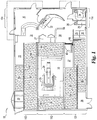
- temporary radiotherapy facility 10 includes a treatment room 20 including a radiotherapy device 25 and a control station 22 for the radiotherapy device 25.
- the interior of facility 10 includes waiting area 30, reception/scheduling area 31, gowning area 35, restroom 34, and storage areas 32, 38.
- the mechanical area 33 contains any necessary heating and chiller equipment and is accessed externally, as is an additional storage area 36.
- the facility further includes an electrical closet 27, staff sink 28 and a potable and waste water tanks 29.
- Access to treatment room 20 is via a radiation shielded door 40 and corridor 37.
- the patient lies on the treatment table 24 and the radiotherapy is administered via radiotherapy device 25 in accordance with the treatment parameters input by the operator at the control station 22.
- Both the treatment table 24 and the radiotherapy device 25 are mounted to a base frame 26 provided in the floor of the treatment room 20.
- the base frame 26 is sufficiently rigid so as to fix the orientation of the device 25 and table 24 relative to each other, though the table 24 and device 25 may themselves be moveable in the conventional fashion relative to the fixed base frame 26.
- the table 24 is typically mounted to a mounting ring (420 in FIG.
- the facility 10 When fully constructed, the facility 10 complies with applicable building codes. Further, the facility 10 is “habitable” in the context of supporting patients and medical personnel during the time of use.
- code compliant and building codes are intended to encompass an ability to construct and configure the basic structural elements of the disclosed combination so as to meet or adhere to what would be required according to applicable building codes. Since the codes of local municipalities might change over time, the structural embodiment disclosed herein is geared toward the code requirements as currently set forth in the 2009 Edition of the ICC International Building Code® (ISBN:1580017258 ), including those other codes referenced therein.
- Facility 10 has been designed using a number of prefabricated modules so as to speed the process of assembling and disassembling the structure, and may be referred to as a Temporary Radiotherapy Vault (TRV).
- TRV Temporary Radiotherapy Vault
- the ground floor is composed of four different modules, each of which has a generally rectangular footprint.
- Modules 101, 102 and 103 are equal in length and are placed along side each other and module 104 is placed across the ends of modules 101, 102, and 103 (right side of FIG. 1 ).
- Alternative configurations or embodiments could incorporate more than four different modules.
- Each of the modules in includes a free standing frame structure, typically made up of a series of interconnected steel C and I beams, that generally define the outer edges of the module. Accordingly, each of the modules may be constructed in the same fashion as the pods detailed in US 2010/0146870 , attached hereto.
- the treatment room is entirely contained within module 102.
- Modules 101, 102 and 103 are designed such that, when assembled, they define a number of void spaces 50, 52, 54, 56, 58, and 60 around the treatment room 20.
- These void spaces i.e., the vessel
- a radiation shielding material M such as a flowable granular fill having a density range of 80-125lb/ft 3 .
- Aligned void spaces e.g. 50 and 54, 54 and 52, 52 and 58
- the granular fill i.e., the shielding material M
- the shielding material M cannot crack due to settling or seismic events.
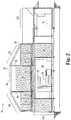
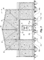
- Roof modules 105 and 106 are designed so as to be placed above modules 101, 102 and 103 and to have their trusses 84 and 82 spanning from the shear wall 64 in module 101 to the shear wall 62 in module 103.
- a supporting panel 80 is then mounted between the trusses 84 and 82, and together with panels 81, 83 integrated into the roof modules 106, 105 supports the shielding material M over the treatment room 20 while maintaining a gap 110 between the underside of the panels 80, 81, 83 and the uppermost portion of the treatment room 20.
- Alternative configurations and embodiments could incorporate additional roof modules in lieu of supporting panels.
- the load of the shielding material directly above the treatment room 20 can be distributed through the trusses to the shear walls 62, 64 rather than bearing on the treatment room itself.
- This gap isolates the treatment room and protects it from the effects of any foundation shifting or sinking that may occur due to the excessive weight of the shielding material above it.
- the upper level shielding areas 70, 72 and 74 that are not directly above the treatment room 20 are open to the lower level void spaces 50, 52, 54, 58.
- Connecting rods 88 span between the upper portions of the trusses 84, 82 and help give shape and support to fabric or membrane roof 92 which is installed once all the shielding material has been delivered.
- module 104 While some of the floor space for control station 22 is provided by module 104, it is preferable to have the relevant computer equipment hardwired to the radiotherapy device 25 in module 102.
- the computer equipment is provided on a wheeled cart so that it can move into the position shown in FIG. 1 from a storage position in module 102.
- the precise quantity and desired distribution of radiation shielding material is dependent on the characteristics of the radiation emitted from device 25.
- the facility 10 is configured to employ an isocentrically arranged high energy linear accelerator, which typically operates in the range of 4-25MV.
- An example would be Varian Medical Systems Trilogy, Palo Alto, CA.
- the total weight of the shielding material may be 1,000,000 lbs or 2,000,000 lbs or more.
- neutron shielding is provided by lining the treatment room with wood panels and borated polyethylene sheets.
- the facility 10 could also be used to perform other types of radiotherapy, such as gamma knife or high dose rate brachytherapy (HDR), which typically operate in the range of 1-3MV.
- HDR high dose rate brachytherapy
- the facility 10 may also be adapted for use with cyclotrons operating in the range of 10-15MV or proton accelerators operating in the range of 40-250MV.
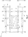
- the foundation 200 for the TRV comprises a pattern ( FIG. 4 ) of elongated beams of reinforced concrete.
- Individual beams of reinforced concrete are conventionally referred to as grade beams, since they are typically constructed at or above grade level.
- the grade beams for the TRV foundation are recessed several inches below-grade (e.g. 3-6inches). The use of below-grade, grade beams makes it easier to return the site to its original condition once the TRV has been removed, since one could simply backfill over the below- grade, grade beams.
- the pattern includes a number of parallel and orthogonal beams and beam segments. These beams underlie various portions of the TRV structure and the layout of FIG. 4 corresponds to the floor plan of FIG. 1 .
- parallel beams 210 and 212 underlie the elongated sides of module 102 and parallel beams 210a and 212a underlie the adjustable supports that are provided along the sides of the base frame 26 and used to level the base frame, as described more fully below.
- Short transverse beams 214, 215 and 216 span between beams 210, 210a and 212, 212a at multiple locations along the lengths of beams 210, 210a, 212 and 212a.
- These short transverse beams 214, 215, 216 serve to provide a degree of integration or coupling between beams 210 and 212, and they also serve to underlie and provide support for the base frame 26.
- beams 214, 215, 216 do not intersect with the outside beams 220 or 230, and thus these outside beams are relatively decoupled from their respective inner beam 212, 212a, , 210, 210a.
- the presence of beams 214, 215, 216 assures that beams 210, 210a are more coupled to beams 212, 212a than they are to beams 220, 230.
- beams 220 and 230 are designed to underlie and provide support to the shear walls 62 and 64 in modules 103 and 101 respectively.
- these shear walls 62, 64 bear the load of all the suspended shielding material that is positioned over the treatment room 20. Because this is a large mass of material, it provides significant inertial resistance to any lateral movement that would develop during a seismic event (i.e. earthquake). As a result, in order to satisfy various building codes, it is generally necessary to have a lateral coupling between the foundation and the shear wall that can withstand the significant lateral stresses.
- the dead load of the suspended shielding material is also positioned far enough away from the therapy room 20, to avoid any impairment to the supporting beams 214, 215, 216 and/or the supporting beams 210a, 212a which may impact the room's geometry and/or the levelness of the base frame 26.
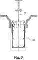
- Supports 160 are generally in the form of an I beam and have a planar base 164 and top plate 162 coupled by a vertical section 166. Support 160 is designed to be mounted in an elongated horizontal slot 168 such as the one formed in grade beam 240. Grade beams 240 and 250 are illustrated in FIG. 4 .
- the planar base 164 of support 160 being recessed into slot 168, the sidewalls of slot 168 provide lateral coupling through contact with the sides of base 164 and vertical span 166. If the slot 168 is initially too long to provide adequate lateral coupling contact, such contact can be facilitated by providing grout into the ends of slot 168.
- support 160 may be reconfigured so as to include additional or different vertical spans between top plate 162 and base 168.
- vertical plates may be added to the ends of the support 160 so as to provide additional coupling between the top plate 162 and the base 168. These end plates would be orthogonal to the vertical span 166 and would increase the overall rigidity of the supports 160.
- Supports 260 are similar to supports 160 in that they also have a planar mounting plate 262 and a planar base 264 and the planar base 264 is received in slot 222 of a grade beam 221.
- the slot 222 includes a pair of intersecting slots such that slot 222 is considered to be elongated in two orthogonal directions.
- the base 264 of support 260 is also of a "+" or intersecting configuration, and in use the base of support 260 is received in slot 222 and engages therewith so as to provide lateral contact coupling in multiple directions.
- Supports 260 may also be supplemented with additional vertical plates.
- additional vertical plates In particular, it is contemplated that four vertical end plates would be attached to the four ends of support 260. Two opposing plates would be attached orthogonal to vertical support 266 and two would be orthogonal to vertical support 268.
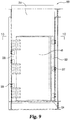
- FIGS. 9 and 10 illustrate the door cassette 300 installed in module 101.
- Door cassette 300 includes a shielding door 40, its surrounding frame parts 320, 330, 324, and a radiation shielding transom area 310 directly above the door 40.
- the entire cassette 300 is configured to be lifted out of module 101 as a whole.
- the lower portion of frame 324 i.e. the threshold
- the hinge side of frame 330 abuts against channel steel in the module 101 and is bolted in place via clamps 336.
- the opposing door side of frame 320 has a clearance that is filled with shim plate 338 and then the door side of frame 320 is bolted to module 101 via clamps 337.
- additional shielding plates 66 are provided in module 101 to provide shielding otherwise lost due to corridor 37, which cannot being filled with granular fill shielding material M.
- One contemplated method according to the present invention involves the identification of a radiotherapy facility having an existing radiotherapy device needing to be taken out of service. Typically, a facility would self identify its needs.
- a site for a temporary radiotherapy facility is identified.
- the site should be suitably close to the existing facility so as to minimize disruption, and may be an empty field or parking lot.
- a foundation for the temporary device is created at the identified site.
- the foundation can be a simple concrete slab, but preferably it is a pattern of recessed grade beams as described previously.
- the temporary radiotherapy facility typically includes a radiotherapy device within a radiation shielding vault, and it may correspond to the TRV previously described.
- the vault may include at least about 1,000,000 lbs of radiation shielding material, such as the granular fill or some other type, as previously described, including water.
- Removal of the temporary facility may include removal of some or all of the components of the TRV and some or all of the radiation shielding material included in the void spaces.
- the TRV is equipped with radiotherapy equipment substantially similar to the equipment to be installed at the existing facility. In this way, the personnel can receive training on the new equipment while operating in the TRV.
- Another inventive method contemplated herein involves maintaining treatment continuity to a patient population during the renovation or construction of a radiotherapy facility. This may be accomplished in connection with an existing (first) radiotherapy facility having a first radiotherapy device, wherein services are provided at the existing facility to a patient population by support staff, the support staff including at least one treatment individual.
- the treatment individual may be, for example, a doctor, a nurse, a therapist, a dosimetrist, or a physicist.
- a second radiotherapy facility is constructed to treat the patient population on a temporary basis, the second facility having a second radiotherapy device within a radiation shielding vault, such as the TRV described previously.
- the treatment individual Upon completion of the temporary facility, the treatment individual is transitioned to the second facility, and he/she provides services at the second facility to the patient population during the renovation and/or upgrade of the first radiotherapy facility. Then, upon completion of the renovation and/or upgrade of the first radiotherapy facility, the treatment individual is transitioned back to the first facility (or to a newly-constructed third facility) where he/she can continue to serve the same patient population.
- the period of transition may be occasioned by an equipment modernization and/or the construction of a wholly-new facility.
- isocenter is a point in three-dimensional space around which all movable axes of the treatment machine revolve.
- a stable isocenter is critical.
- isocenter is defined and specified as a sphere having a radius of no more than 2 mm in diameter, for example 1mm in diameter.
- the targeted treatment area usually a tumor, is placed at isocenter during treatment.
- various components of the treatment machine gantry, collimator, and couch
- All structures can sink, shift, or even move. They are engineered to do this without any overall impairment to the structure.
- a shift in a wall, floor or ceiling in a therapy room has consequences not normally part of the engineer's design challenge.
- soil settlement is controlled since the slab can bridge over settlement areas, just like a sheet of plywood would bridge your shoe depressions in the mud. If there is any settlement, it will be mitigated by the slab, or at least slowed down so as to happen over a longer period of time, typically years.
- Rapid settlement in localized areas can have an effect on grade beams, since they do not have the benefit of the monolithic slab.
- the disclosed approach as set forth herein, is to build in tolerance by making the therapy room an independent structural sanctuary that is not impacted by any settlement caused by the huge shielding mass, especially the mass directly above the treatment room. This is achieved by creating a six inch gap between the therapy room structure and the supported shielding mass above. Further contributing to this achievement is allowing the grade beams to move independently and further, separating the shielding mass load from the therapy room load by a suitable distance on independent grade beams.
- the base frame 26 includes mounting ring 240 for the treatment table 24 (not shown) that allows the treatment table 24 to be rotated about a vertical axis, and the radiotherapy machine 25 (not shown) is mounted to the base frame 26 with a gantry that allows the radiation emitting portion of the machine 25 to be rotated about a horizontal axis, and the base frame is sufficiently rigid and monolithic so as to maintain the relative alignment of the table 24 and machine 25 and their respective horizontal and vertical rotation axes.
- the treatment room module 102 is made up of a freestanding outer frame assembly.
- the floor structure of this frame includes lateral side members 102a, 102b. These side members 102a, 102b extend the length of the module 102 and are positioned over the grade beams 210, 212 as shown in FIG. 4 .
- the floor structure of module 102 also includes a pair of cross members 102c, 102d that extend between the side members 102a and 102b so as to be positioned over the grade beams 214 and 216 respectively.
- side member 102a and its underlying grade beam 210 have been omitted from FIG. 11 .
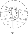
- the base frame 26 is provided with a number of mounting flanges 412, only one of which is shown in the detail of FIG. 12 . These mounting flanges are welded to the side rails 26a of the base frame 26 at each of its four corners, thereby providing an integral connection between the flanges and the base frame 26.
- the flanges 412 are coupled to the cross members by a series of bolts 410.
- the bolt holes in the flanges 412 are enlarged slightly relative to the shank of the bolt, for example being slotted or elongated in the vertical direction.
- the bolts 410 are loosened slightly, there is a degree of play in the connection between the base frame 26 and the module cross member 102c. This allows the orientation of the base frame 26 to be adjusted slightly from the orientation of the remainder of the module 102, as explained more fully below.
- an adjustable support 400 is provided near each of the four corners of the base frame 26.
- Support 400 includes a threaded rod 404 having a base 408 at its lower end.
- the threaded portion of the rod 404 is received in a correspondingly threaded vertical bore of block 402, which is welded to the side rail 26a of base frame 26.
- rotation of the rod 404 which is accomplished by turning the captured nut 406 at its upper end, serves to raise or lower the rod, and thus the base 408, relative to the side rail 26a of the base frame. Accordingly, once the base 408 has come into contact with the underlying foundation (e.g.
- the adjustments to the orientation of the base frame 26 made possible by the present invention can have a number of beneficial applications, for example, by allowing for adjustments to be made at the time of initial installation or after a period of use, for example to compensate for any adverse effects due to settling.
- trap doors may be provided in the floor of the treatment room above each of the supports, thereby enabling access to each support with minimal disruption to any floor finishing that may be installed.
- the process of leveling the base frame 26 may proceed as follows.
- the base frame 26 is adjustable mounted with the outer frame assembly of module 102.
- This outer frame assembly is then placed on a foundation.
- the radiotherapy machine 25 and treatment table 24 have already been mounted to the base frame 26 at the factory, but if not, they may be brought to the site and mounted to the base frame independently.
- the process of placing it on the foundation is typically accomplished with a container mover, such as a crane.
- the foundation may be a concrete slab or a pattern of grade beams, and the outer frame assembly/module 102 may be placed directly on the foundation or onto supports extending from the foundation.
- the levelness of the base frame is checked, which may be accomplished using conventional leveling equipment (i.e. bubble levels). If the base frame is determined to be out of level, the mounting bolts 410 securing the base frame 26 the outer fame (i.e. cross members 102c and 102) are loosened and the adjustable supports 400 are used to raise portions of the base frame 26 as described above. Any number of the supports 400 may be utilized to bring the base frame 26 to level, such as one, two, three or all four of the supports, and the levelness of the base frame may be continually checked during the leveling process.
- conventional leveling equipment i.e. bubble levels
Landscapes
- Engineering & Computer Science (AREA)
- Architecture (AREA)
- General Engineering & Computer Science (AREA)
- Civil Engineering (AREA)
- Structural Engineering (AREA)
- Mechanical Engineering (AREA)
- High Energy & Nuclear Physics (AREA)
- Paleontology (AREA)
- Mining & Mineral Resources (AREA)
- General Life Sciences & Earth Sciences (AREA)
- Life Sciences & Earth Sciences (AREA)
- Physics & Mathematics (AREA)
- Health & Medical Sciences (AREA)
- Public Health (AREA)
- Radiation-Therapy Devices (AREA)
Priority Applications (1)
| Application Number | Priority Date | Filing Date | Title |
|---|---|---|---|
| PL14854631T PL3058574T3 (pl) | 2013-10-15 | 2014-10-15 | Moduł bunkra radiacyjnego z regulowaną ramą podstawy |
Applications Claiming Priority (2)
| Application Number | Priority Date | Filing Date | Title |
|---|---|---|---|
| US201361891286P | 2013-10-15 | 2013-10-15 | |
| PCT/US2014/060588 WO2015057770A1 (en) | 2013-10-15 | 2014-10-15 | Radiation vault module with adjustable base frame |
Publications (3)
| Publication Number | Publication Date |
|---|---|
| EP3058574A1 EP3058574A1 (en) | 2016-08-24 |
| EP3058574A4 EP3058574A4 (en) | 2017-06-14 |
| EP3058574B1 true EP3058574B1 (en) | 2019-12-04 |
Family
ID=52808466
Family Applications (1)
| Application Number | Title | Priority Date | Filing Date |
|---|---|---|---|
| EP14854631.0A Active EP3058574B1 (en) | 2013-10-15 | 2014-10-15 | Radiation vault module with adjustable base frame |
Country Status (6)
| Country | Link |
|---|---|
| US (1) | US10876675B2 (pl) |
| EP (1) | EP3058574B1 (pl) |
| DK (1) | DK3058574T3 (pl) |
| ES (1) | ES2774944T3 (pl) |
| PL (1) | PL3058574T3 (pl) |
| WO (1) | WO2015057770A1 (pl) |
Cited By (1)
| Publication number | Priority date | Publication date | Assignee | Title |
|---|---|---|---|---|
| US10876675B2 (en) | 2013-10-15 | 2020-12-29 | Rad Technology Medical Systems Llc | Radiation vault module with adjustable base frame |
Families Citing this family (7)
| Publication number | Priority date | Publication date | Assignee | Title |
|---|---|---|---|---|
| CN105304153A (zh) * | 2015-11-20 | 2016-02-03 | 共享铸钢有限公司 | 伽马探伤机屏蔽防护装置 |
| FI128039B (en) * | 2018-05-21 | 2019-08-15 | Vetrospace Oy | Soundproof and hygienic space |
| US11000699B2 (en) | 2018-11-20 | 2021-05-11 | Alliance Oncology, LLC | Mobile radiation oncology coach system with internal and/or external shielding for same |
| CA3117053A1 (en) * | 2018-11-20 | 2020-05-28 | Dana-Farber Cancer Institute, Inc. | Self shielded cyclotron radiation patch |
| US11549258B2 (en) * | 2019-08-08 | 2023-01-10 | Daniel John Shields | Radiation shielding structure |
| CN110867269B (zh) * | 2019-11-27 | 2021-12-03 | 中广核工程有限公司 | 一种乏燃料干式贮存立式贮存模块 |
| WO2023097163A1 (en) * | 2021-11-23 | 2023-06-01 | Optima, Inc. | Modular habitable structures, and associated systems and methods |
Family Cites Families (80)
| Publication number | Priority date | Publication date | Assignee | Title |
|---|---|---|---|---|
| US3067843A (en) * | 1962-12-11 | Floor paneling arrangement | ||
| US2605066A (en) * | 1946-12-21 | 1952-07-29 | Firestone Tire & Rubber Co | Air spring for heavy machinery |
| US2779559A (en) * | 1953-03-19 | 1957-01-29 | Bertuch Hans | Machine mounting device |
| US2954647A (en) * | 1957-04-11 | 1960-10-04 | Lee Hsiang Kai | Adjustable anchoring device |
| US2952947A (en) * | 1958-01-28 | 1960-09-20 | White Paul | Anchor bolt assembly |
| US3222030A (en) * | 1964-06-22 | 1965-12-07 | Unistrut Corp | Floor structure elevating device |
| US3557777A (en) * | 1967-05-04 | 1971-01-26 | David Cohen | Magnetic study of bioelectric phenomena |
| US3831329A (en) * | 1969-02-14 | 1974-08-27 | Glen Crete Prod Co | Building construction system |
| US3606704A (en) * | 1969-05-02 | 1971-09-21 | Resilient Services Inc | Elevated floor structure |
| DE1948632C3 (de) * | 1969-09-26 | 1973-12-20 | Licentia Patent-Verwaltungs-Gmbh, 6000 Frankfurt | Bestrahlungsanlage fur Neutronen therapie |
| US3713259A (en) * | 1971-04-16 | 1973-01-30 | G Tkach | Combination anchor and support utilized to secure a mobile home to an underlying foundation |
| US3704560A (en) * | 1971-06-18 | 1972-12-05 | United States Steel Corp | Support assembly |
| US3747951A (en) * | 1971-08-16 | 1973-07-24 | M Brown | Emergency support |
| US3988622A (en) * | 1972-12-11 | 1976-10-26 | Bbc Brown Boveri & Company Limited | Dynamo-electric machine with prestressed laminated stator component |
| US3971175A (en) * | 1973-07-03 | 1976-07-27 | Houilleres Du Bassin Du Nord Et Du Pas-De-Calais | Factory-made habitation cell |
| AT321064B (de) * | 1973-09-25 | 1975-03-10 | Gfm Fertigungstechnik | Schmiedepresse mit einem liegenden Maschinengestell |
| CH584865A5 (pl) * | 1975-05-07 | 1977-02-15 | Bbc Brown Boveri & Cie | |
| FR2356777A1 (fr) * | 1976-06-28 | 1978-01-27 | Royer Fernand | Element modulaire pour construction d'habitation |
| JPS56100906A (en) * | 1980-01-08 | 1981-08-13 | Masaya Nagashima | Temporarily built bridge |
| US4438610A (en) * | 1982-04-14 | 1984-03-27 | Fifer James T | Clamped access floor panel assembly |
| USRE33220E (en) * | 1984-02-13 | 1990-05-22 | Interstitial Systems, Inc. | Modular combination floor support and electrical isolation system for use in building structures |
| US4785593A (en) * | 1986-10-27 | 1988-11-22 | Munoz Jr Jose C | Structural building system |
| US4846436A (en) * | 1987-06-08 | 1989-07-11 | Vibro Dynamics Corporation | Power assisted equipment mounting system |
| US5081071A (en) * | 1988-04-05 | 1992-01-14 | Biomagnetic Technologies, Inc. | Magnetically shielded enclosure |
| US4850162A (en) * | 1988-07-26 | 1989-07-25 | H. H. Robertson Company | Access floor system |
| US5110082A (en) * | 1988-09-21 | 1992-05-05 | Rowan Jr Robert L | Adjustable apparatus for supporting machinery or other load |
| US5016338A (en) * | 1988-09-21 | 1991-05-21 | Rowan Jr Robert L | Method for adjusting the vertical position of a frame on a foundation |
| US4959504A (en) * | 1988-11-22 | 1990-09-25 | Magnashield Technologies, Inc. | Magnetically and radio frequency shielded enclosure |
| EP0537799A1 (en) * | 1989-05-17 | 1993-04-21 | Naka Corporation | Device and structure for supporting floor panels |
| US5043529A (en) * | 1990-07-13 | 1991-08-27 | Biomagnetic Technologies, Inc. | Construction of shielded rooms using sealants that prevent electromagnetic and magnetic field leakage |
| US5167098A (en) * | 1991-02-22 | 1992-12-01 | The Will-Burt Company | Fire resistant modular building |
| DE4139387A1 (de) * | 1991-11-29 | 1993-06-03 | Asea Brown Boveri | Anordnung zur befestigung eines maschinenteils auf einem fundament |
| CA2061072C (en) * | 1992-02-12 | 1994-05-17 | Richard C. Ellithorpe | Adjustable column cap or base |
| US5516069A (en) * | 1994-09-15 | 1996-05-14 | Hanna; Maxwell H. | Adjustable construction support apparatus |
| FI95307C (fi) * | 1994-12-27 | 1996-01-10 | Euroshield Oy | Magneettisesti suojatun huoneen kannatuspilarijärjestelmä |
| US5695443A (en) * | 1996-07-26 | 1997-12-09 | Brent; Robert W. | High energy radiation emission shelter and method of making the same |
| US6282848B1 (en) * | 1998-05-08 | 2001-09-04 | Imedco Ag | Floor, ceiling and wall construction for a magnetically shielded room |
| US6026975A (en) * | 1998-12-17 | 2000-02-22 | Slater; Electus P. | Above ground storage tank for holding combustible material and supporting equipment thereon |
| US6257437B1 (en) * | 1998-12-17 | 2001-07-10 | Electus P. Slater | Above ground storage tank for holding combustible material and supporting equipment thereon |
| WO2002010634A1 (en) * | 2000-07-31 | 2002-02-07 | Hoppmann Corporation | Machine leveler and method |
| JP3545700B2 (ja) * | 2000-12-08 | 2004-07-21 | 鹿島建設株式会社 | ステンレス床構築方法およびステンレス床 |
| GB0100372D0 (en) * | 2001-01-06 | 2001-02-14 | Owen George | Support apparatus |
| ES2215813T3 (es) * | 2001-03-05 | 2004-10-16 | Brainlab Ag | Metodo para crear o actualizar un plan de tratamiento de radiaciones. |
| US6404845B1 (en) * | 2001-05-09 | 2002-06-11 | Philips Medical Systems (Cleveland), Inc. | Aerostatic rotor bearing |
| US6973758B2 (en) * | 2001-05-14 | 2005-12-13 | Rad Technology, Llc | Shielded structure for radiation treatment equipment and method of assembly |
| US6772564B2 (en) * | 2001-07-11 | 2004-08-10 | Richard Joseph Leon | Unitized, pre-fabricated raised access floor arrangement, installation and leveling method, and automatized leveling tool |
| DE10134539A1 (de) * | 2001-07-16 | 2003-02-13 | Siemens Ag | Abschirmkabine |
| US6591562B2 (en) * | 2001-08-20 | 2003-07-15 | Raymond M. L. Ting | Apparatus for securing curtain wall supports |
| US6648295B2 (en) * | 2001-10-02 | 2003-11-18 | Andrew James Herren | Vibration and sound dampener for heavy machinery |
| JP2003124679A (ja) * | 2001-10-15 | 2003-04-25 | Nikon Corp | 磁気シールドルーム、磁気シールド方法及び露光装置 |
| US6626264B1 (en) * | 2001-10-30 | 2003-09-30 | Igt | Radio frequency shielded and acoustically insulated enclosure |
| JP2003298276A (ja) * | 2002-04-02 | 2003-10-17 | Technol Network Inc | 防振型磁気シールドクリーンルームとその施工法 |
| AU2003280490A1 (en) * | 2002-07-01 | 2004-01-19 | Elekta Ab (Publ) | A mobile building unit as well as a building and a method for constructing the building |
| US6941599B2 (en) * | 2002-08-20 | 2005-09-13 | Aktina Medical Corp. | Radiotherapy treatment and imaging patient support table |
| US20040261333A1 (en) * | 2002-10-25 | 2004-12-30 | Whittaker Wayne H. | Seismic restraint apparatus |
| JP3588097B2 (ja) * | 2003-02-06 | 2004-11-10 | 有限会社泰成電機工業 | 遮音性床構造 |
| US20040163334A1 (en) * | 2003-02-24 | 2004-08-26 | Carlson Bruce Kenneth Oscar | Adjustable beam support |
| ATE427450T1 (de) * | 2003-06-27 | 2009-04-15 | Alstom Technology Ltd | Befestigungsvorrichtung eines maschinenfusses einer maschine und verfahren zur befestigung desselben |
| US6731968B2 (en) * | 2003-07-29 | 2004-05-04 | 4-D Neuroimaging | Magnetically shielded room with internal active magnetic field cancellation, and its use |
| US7210557B2 (en) * | 2004-04-06 | 2007-05-01 | Ets-Lindgren, L.P. | Low profile acoustic flooring |
| US8028476B1 (en) * | 2004-12-13 | 2011-10-04 | Alford Michael R | Pool leveling system |
| US7193227B2 (en) * | 2005-01-24 | 2007-03-20 | Hitachi, Ltd. | Ion beam therapy system and its couch positioning method |
| JP4219905B2 (ja) * | 2005-02-25 | 2009-02-04 | 株式会社日立製作所 | 放射線治療装置の回転ガントリー |
| US7328879B1 (en) * | 2005-06-03 | 2008-02-12 | The United States Of America As Represented By The Secretary Of The Navy | Equipment installation support on foundation |
| JP3882843B2 (ja) | 2005-06-30 | 2007-02-21 | 株式会社日立製作所 | 回転照射装置 |
| US20070039258A1 (en) * | 2005-08-19 | 2007-02-22 | Walker John R Iii | Adjustable attachment system |
| US7530616B2 (en) * | 2006-05-19 | 2009-05-12 | Breya, Llc. | Mobile radiation therapy |
| JP5134219B2 (ja) * | 2006-07-27 | 2013-01-30 | 株式会社日立製作所 | 建屋の建設方法 |
| US7373676B2 (en) * | 2006-09-21 | 2008-05-20 | Aktina Medical Corporation | Patient support apparatus and method therefor |
| WO2008055292A1 (en) * | 2006-11-06 | 2008-05-15 | Weeks Group Pty Ltd | A floor pier support |
| DE102007003878B4 (de) * | 2007-01-25 | 2008-10-02 | Siemens Ag | Partikeltherapie-Anlage mit beweglichem Bodensegment |
| JP4228018B2 (ja) * | 2007-02-16 | 2009-02-25 | 三菱重工業株式会社 | 医療装置 |
| US20100024353A1 (en) * | 2008-07-29 | 2010-02-04 | Green Horizon Manufacturing Llc | Method for deploying prefabricated structures arranged in a complementary layout |
| US20100257812A1 (en) * | 2009-04-13 | 2010-10-14 | Schultz Christopher A | Adjustable Attachment System |
| NZ596424A (en) * | 2009-04-17 | 2013-09-27 | Petar Zlatar | A noise attenuating and vibration dampening pedestal for an access floor assembly |
| HUE033391T2 (en) * | 2009-10-31 | 2017-12-28 | Rad Tech Medical Systems Llc | A method for providing radiation therapy |
| US20110302854A1 (en) * | 2010-06-09 | 2011-12-15 | Sustainable Building Innovations, Inc. | Floor leveling system |
| US8763329B2 (en) * | 2010-07-13 | 2014-07-01 | Kai N. MOSEID | Precise patient table cavity form |
| US8627601B2 (en) * | 2010-12-23 | 2014-01-14 | Veritas Medical Solutions Llc | Rotating radiation shielded entrance assembly |
| PL3058574T3 (pl) * | 2013-10-15 | 2020-06-01 | Rad Technology Medical Systems, Llc | Moduł bunkra radiacyjnego z regulowaną ramą podstawy |
-
2014
- 2014-10-15 PL PL14854631T patent/PL3058574T3/pl unknown
- 2014-10-15 US US14/514,509 patent/US10876675B2/en active Active
- 2014-10-15 DK DK14854631.0T patent/DK3058574T3/da active
- 2014-10-15 EP EP14854631.0A patent/EP3058574B1/en active Active
- 2014-10-15 ES ES14854631T patent/ES2774944T3/es active Active
- 2014-10-15 WO PCT/US2014/060588 patent/WO2015057770A1/en not_active Ceased
Non-Patent Citations (1)
| Title |
|---|
| None * |
Cited By (1)
| Publication number | Priority date | Publication date | Assignee | Title |
|---|---|---|---|---|
| US10876675B2 (en) | 2013-10-15 | 2020-12-29 | Rad Technology Medical Systems Llc | Radiation vault module with adjustable base frame |
Also Published As
| Publication number | Publication date |
|---|---|
| EP3058574A4 (en) | 2017-06-14 |
| US10876675B2 (en) | 2020-12-29 |
| PL3058574T3 (pl) | 2020-06-01 |
| DK3058574T3 (da) | 2020-03-09 |
| US20150101275A1 (en) | 2015-04-16 |
| EP3058574A1 (en) | 2016-08-24 |
| WO2015057770A1 (en) | 2015-04-23 |
| ES2774944T3 (es) | 2020-07-23 |
Similar Documents
| Publication | Publication Date | Title |
|---|---|---|
| US11982081B2 (en) | Relocatable radiation vault and methods of assembly and use | |
| US10876675B2 (en) | Radiation vault module with adjustable base frame | |
| US7665249B2 (en) | Shielded structure for radiation treatment equipment and method of assembly | |
| US20040118081A1 (en) | Ion beam facility | |
| US20180110666A1 (en) | Prefabricated modular radiation therapy vault design | |
| US8101933B2 (en) | Medical device | |
| WO1998004323A1 (en) | High energy radiation emission shelter and method of making the same | |
| GB2192213A (en) | Adjustable floor and column support system | |
| US11479966B2 (en) | Building elements and structures having materials with shielding properties | |
| US8763329B2 (en) | Precise patient table cavity form | |
| CA3117993A1 (en) | Mobile radiation oncology coach system with internal and/or external shielding for same | |
| JP2018100550A (ja) | 放射線照射室を備えた医療用免震建物 | |
| CN223724256U (zh) | 一种大型辐射装置的混凝土屏蔽体结构 | |
| Rabin et al. | Compact designs for comprehensive proton beam clinical facilities | |
| US12571201B2 (en) | Concrete-fillable prefabricated cartridges for constructing structural concrete buildings and construction methods therefor | |
| Szegedi et al. | Seismic reinforcement of a linac installation | |
| Ryskamp et al. | Design of the WSU Epithermal Neutron Beam Extraction Facility for BNCT | |
| Reimoser et al. | Engineering design and study of the beam position accuracy in the “Riesenrad” ion gantry | |
| Reimoser | Development and Engineering Design of a Novel Exocentric Carbon-Ion Gantry for Cancer Therapy: The" Riesenrad" Gantry |
Legal Events
| Date | Code | Title | Description |
|---|---|---|---|
| PUAI | Public reference made under article 153(3) epc to a published international application that has entered the european phase |
Free format text: ORIGINAL CODE: 0009012 |
|
| 17P | Request for examination filed |
Effective date: 20160512 |
|
| AK | Designated contracting states |
Kind code of ref document: A1 Designated state(s): AL AT BE BG CH CY CZ DE DK EE ES FI FR GB GR HR HU IE IS IT LI LT LU LV MC MK MT NL NO PL PT RO RS SE SI SK SM TR |
|
| AX | Request for extension of the european patent |
Extension state: BA ME |
|
| DAX | Request for extension of the european patent (deleted) | ||
| A4 | Supplementary search report drawn up and despatched |
Effective date: 20170511 |
|
| RIC1 | Information provided on ipc code assigned before grant |
Ipc: G21F 3/04 20060101ALI20170505BHEP Ipc: E04H 3/08 20060101ALI20170505BHEP Ipc: E04F 15/02 20060101ALI20170505BHEP Ipc: E02D 27/44 20060101ALI20170505BHEP Ipc: G21F 7/00 20060101AFI20170505BHEP Ipc: F16M 7/00 20060101ALI20170505BHEP Ipc: B23Q 1/00 20060101ALI20170505BHEP Ipc: G01R 33/42 20060101ALI20170505BHEP |
|
| STAA | Information on the status of an ep patent application or granted ep patent |
Free format text: STATUS: EXAMINATION IS IN PROGRESS |
|
| 17Q | First examination report despatched |
Effective date: 20180409 |
|
| GRAP | Despatch of communication of intention to grant a patent |
Free format text: ORIGINAL CODE: EPIDOSNIGR1 |
|
| STAA | Information on the status of an ep patent application or granted ep patent |
Free format text: STATUS: GRANT OF PATENT IS INTENDED |
|
| INTG | Intention to grant announced |
Effective date: 20190508 |
|
| GRAS | Grant fee paid |
Free format text: ORIGINAL CODE: EPIDOSNIGR3 |
|
| GRAA | (expected) grant |
Free format text: ORIGINAL CODE: 0009210 |
|
| STAA | Information on the status of an ep patent application or granted ep patent |
Free format text: STATUS: THE PATENT HAS BEEN GRANTED |
|
| AK | Designated contracting states |
Kind code of ref document: B1 Designated state(s): AL AT BE BG CH CY CZ DE DK EE ES FI FR GB GR HR HU IE IS IT LI LT LU LV MC MK MT NL NO PL PT RO RS SE SI SK SM TR |
|
| REG | Reference to a national code |
Ref country code: GB Ref legal event code: FG4D |
|
| REG | Reference to a national code |
Ref country code: CH Ref legal event code: EP |
|
| REG | Reference to a national code |
Ref country code: AT Ref legal event code: REF Ref document number: 1210408 Country of ref document: AT Kind code of ref document: T Effective date: 20191215 |
|
| REG | Reference to a national code |
Ref country code: DE Ref legal event code: R096 Ref document number: 602014058007 Country of ref document: DE |
|
| REG | Reference to a national code |
Ref country code: IE Ref legal event code: FG4D |
|
| REG | Reference to a national code |
Ref country code: CH Ref legal event code: NV Representative=s name: SERVOPATENT GMBH, CH |
|
| REG | Reference to a national code |
Ref country code: DK Ref legal event code: T3 Effective date: 20200305 |
|
| REG | Reference to a national code |
Ref country code: SE Ref legal event code: TRGR |
|
| REG | Reference to a national code |
Ref country code: NL Ref legal event code: FP |
|
| REG | Reference to a national code |
Ref country code: LT Ref legal event code: MG4D |
|
| PG25 | Lapsed in a contracting state [announced via postgrant information from national office to epo] |
Ref country code: LT Free format text: LAPSE BECAUSE OF FAILURE TO SUBMIT A TRANSLATION OF THE DESCRIPTION OR TO PAY THE FEE WITHIN THE PRESCRIBED TIME-LIMIT Effective date: 20191204 Ref country code: NO Free format text: LAPSE BECAUSE OF FAILURE TO SUBMIT A TRANSLATION OF THE DESCRIPTION OR TO PAY THE FEE WITHIN THE PRESCRIBED TIME-LIMIT Effective date: 20200304 Ref country code: GR Free format text: LAPSE BECAUSE OF FAILURE TO SUBMIT A TRANSLATION OF THE DESCRIPTION OR TO PAY THE FEE WITHIN THE PRESCRIBED TIME-LIMIT Effective date: 20200305 Ref country code: FI Free format text: LAPSE BECAUSE OF FAILURE TO SUBMIT A TRANSLATION OF THE DESCRIPTION OR TO PAY THE FEE WITHIN THE PRESCRIBED TIME-LIMIT Effective date: 20191204 Ref country code: BG Free format text: LAPSE BECAUSE OF FAILURE TO SUBMIT A TRANSLATION OF THE DESCRIPTION OR TO PAY THE FEE WITHIN THE PRESCRIBED TIME-LIMIT Effective date: 20200304 |
|
| PG25 | Lapsed in a contracting state [announced via postgrant information from national office to epo] |
Ref country code: HR Free format text: LAPSE BECAUSE OF FAILURE TO SUBMIT A TRANSLATION OF THE DESCRIPTION OR TO PAY THE FEE WITHIN THE PRESCRIBED TIME-LIMIT Effective date: 20191204 Ref country code: RS Free format text: LAPSE BECAUSE OF FAILURE TO SUBMIT A TRANSLATION OF THE DESCRIPTION OR TO PAY THE FEE WITHIN THE PRESCRIBED TIME-LIMIT Effective date: 20191204 |
|
| REG | Reference to a national code |
Ref country code: SK Ref legal event code: T3 Ref document number: E 33709 Country of ref document: SK |
|
| REG | Reference to a national code |
Ref country code: CH Ref legal event code: PCAR Free format text: NEW ADDRESS: WANNERSTRASSE 9/1, 8045 ZUERICH (CH) |
|
| PG25 | Lapsed in a contracting state [announced via postgrant information from national office to epo] |
Ref country code: AL Free format text: LAPSE BECAUSE OF FAILURE TO SUBMIT A TRANSLATION OF THE DESCRIPTION OR TO PAY THE FEE WITHIN THE PRESCRIBED TIME-LIMIT Effective date: 20191204 |
|
| REG | Reference to a national code |
Ref country code: ES Ref legal event code: FG2A Ref document number: 2774944 Country of ref document: ES Kind code of ref document: T3 Effective date: 20200723 |
|
| PG25 | Lapsed in a contracting state [announced via postgrant information from national office to epo] |
Ref country code: PT Free format text: LAPSE BECAUSE OF FAILURE TO SUBMIT A TRANSLATION OF THE DESCRIPTION OR TO PAY THE FEE WITHIN THE PRESCRIBED TIME-LIMIT Effective date: 20200429 Ref country code: RO Free format text: LAPSE BECAUSE OF FAILURE TO SUBMIT A TRANSLATION OF THE DESCRIPTION OR TO PAY THE FEE WITHIN THE PRESCRIBED TIME-LIMIT Effective date: 20191204 Ref country code: EE Free format text: LAPSE BECAUSE OF FAILURE TO SUBMIT A TRANSLATION OF THE DESCRIPTION OR TO PAY THE FEE WITHIN THE PRESCRIBED TIME-LIMIT Effective date: 20191204 |
|
| PG25 | Lapsed in a contracting state [announced via postgrant information from national office to epo] |
Ref country code: IS Free format text: LAPSE BECAUSE OF FAILURE TO SUBMIT A TRANSLATION OF THE DESCRIPTION OR TO PAY THE FEE WITHIN THE PRESCRIBED TIME-LIMIT Effective date: 20200404 Ref country code: SM Free format text: LAPSE BECAUSE OF FAILURE TO SUBMIT A TRANSLATION OF THE DESCRIPTION OR TO PAY THE FEE WITHIN THE PRESCRIBED TIME-LIMIT Effective date: 20191204 |
|
| REG | Reference to a national code |
Ref country code: DE Ref legal event code: R097 Ref document number: 602014058007 Country of ref document: DE |
|
| REG | Reference to a national code |
Ref country code: AT Ref legal event code: MK05 Ref document number: 1210408 Country of ref document: AT Kind code of ref document: T Effective date: 20191204 |
|
| PLBE | No opposition filed within time limit |
Free format text: ORIGINAL CODE: 0009261 |
|
| STAA | Information on the status of an ep patent application or granted ep patent |
Free format text: STATUS: NO OPPOSITION FILED WITHIN TIME LIMIT |
|
| 26N | No opposition filed |
Effective date: 20200907 |
|
| PG25 | Lapsed in a contracting state [announced via postgrant information from national office to epo] |
Ref country code: AT Free format text: LAPSE BECAUSE OF FAILURE TO SUBMIT A TRANSLATION OF THE DESCRIPTION OR TO PAY THE FEE WITHIN THE PRESCRIBED TIME-LIMIT Effective date: 20191204 Ref country code: SI Free format text: LAPSE BECAUSE OF FAILURE TO SUBMIT A TRANSLATION OF THE DESCRIPTION OR TO PAY THE FEE WITHIN THE PRESCRIBED TIME-LIMIT Effective date: 20191204 |
|
| PG25 | Lapsed in a contracting state [announced via postgrant information from national office to epo] |
Ref country code: MC Free format text: LAPSE BECAUSE OF FAILURE TO SUBMIT A TRANSLATION OF THE DESCRIPTION OR TO PAY THE FEE WITHIN THE PRESCRIBED TIME-LIMIT Effective date: 20191204 Ref country code: LU Free format text: LAPSE BECAUSE OF NON-PAYMENT OF DUE FEES Effective date: 20201015 |
|
| PG25 | Lapsed in a contracting state [announced via postgrant information from national office to epo] |
Ref country code: TR Free format text: LAPSE BECAUSE OF FAILURE TO SUBMIT A TRANSLATION OF THE DESCRIPTION OR TO PAY THE FEE WITHIN THE PRESCRIBED TIME-LIMIT Effective date: 20191204 Ref country code: MT Free format text: LAPSE BECAUSE OF FAILURE TO SUBMIT A TRANSLATION OF THE DESCRIPTION OR TO PAY THE FEE WITHIN THE PRESCRIBED TIME-LIMIT Effective date: 20191204 Ref country code: CY Free format text: LAPSE BECAUSE OF FAILURE TO SUBMIT A TRANSLATION OF THE DESCRIPTION OR TO PAY THE FEE WITHIN THE PRESCRIBED TIME-LIMIT Effective date: 20191204 |
|
| PG25 | Lapsed in a contracting state [announced via postgrant information from national office to epo] |
Ref country code: MK Free format text: LAPSE BECAUSE OF FAILURE TO SUBMIT A TRANSLATION OF THE DESCRIPTION OR TO PAY THE FEE WITHIN THE PRESCRIBED TIME-LIMIT Effective date: 20191204 |
|
| PGFP | Annual fee paid to national office [announced via postgrant information from national office to epo] |
Ref country code: SK Payment date: 20221013 Year of fee payment: 9 Ref country code: LV Payment date: 20221019 Year of fee payment: 9 Ref country code: CZ Payment date: 20221013 Year of fee payment: 9 |
|
| REG | Reference to a national code |
Ref country code: SK Ref legal event code: MM4A Ref document number: E 33709 Country of ref document: SK Effective date: 20231015 |
|
| PG25 | Lapsed in a contracting state [announced via postgrant information from national office to epo] |
Ref country code: CZ Free format text: LAPSE BECAUSE OF NON-PAYMENT OF DUE FEES Effective date: 20231015 |
|
| PG25 | Lapsed in a contracting state [announced via postgrant information from national office to epo] |
Ref country code: SK Free format text: LAPSE BECAUSE OF NON-PAYMENT OF DUE FEES Effective date: 20231015 |
|
| PG25 | Lapsed in a contracting state [announced via postgrant information from national office to epo] |
Ref country code: SK Free format text: LAPSE BECAUSE OF NON-PAYMENT OF DUE FEES Effective date: 20231015 Ref country code: CZ Free format text: LAPSE BECAUSE OF NON-PAYMENT OF DUE FEES Effective date: 20231015 |
|
| PG25 | Lapsed in a contracting state [announced via postgrant information from national office to epo] |
Ref country code: LV Free format text: LAPSE BECAUSE OF NON-PAYMENT OF DUE FEES Effective date: 20231015 |
|
| REG | Reference to a national code |
Ref country code: CH Ref legal event code: U11 Free format text: ST27 STATUS EVENT CODE: U-0-0-U10-U11 (AS PROVIDED BY THE NATIONAL OFFICE) Effective date: 20251101 |
|
| PGFP | Annual fee paid to national office [announced via postgrant information from national office to epo] |
Ref country code: NL Payment date: 20251015 Year of fee payment: 12 |
|
| PGFP | Annual fee paid to national office [announced via postgrant information from national office to epo] |
Ref country code: DE Payment date: 20251014 Year of fee payment: 12 |
|
| PGFP | Annual fee paid to national office [announced via postgrant information from national office to epo] |
Ref country code: GB Payment date: 20251016 Year of fee payment: 12 |
|
| PGFP | Annual fee paid to national office [announced via postgrant information from national office to epo] |
Ref country code: DK Payment date: 20251029 Year of fee payment: 12 Ref country code: IT Payment date: 20251030 Year of fee payment: 12 |
|
| PGFP | Annual fee paid to national office [announced via postgrant information from national office to epo] |
Ref country code: FR Payment date: 20251023 Year of fee payment: 12 |
|
| PGFP | Annual fee paid to national office [announced via postgrant information from national office to epo] |
Ref country code: BE Payment date: 20251015 Year of fee payment: 12 |
|
| PGFP | Annual fee paid to national office [announced via postgrant information from national office to epo] |
Ref country code: CH Payment date: 20251101 Year of fee payment: 12 Ref country code: SE Payment date: 20251010 Year of fee payment: 12 |
|
| PGFP | Annual fee paid to national office [announced via postgrant information from national office to epo] |
Ref country code: IE Payment date: 20251024 Year of fee payment: 12 |
|
| PGFP | Annual fee paid to national office [announced via postgrant information from national office to epo] |
Ref country code: PL Payment date: 20251009 Year of fee payment: 12 |
|
| PGFP | Annual fee paid to national office [announced via postgrant information from national office to epo] |
Ref country code: ES Payment date: 20251104 Year of fee payment: 12 |