EP3057848B1 - Procédé de commande de comportement de véhicule - Google Patents
Procédé de commande de comportement de véhicule Download PDFInfo
- Publication number
- EP3057848B1 EP3057848B1 EP14795881.3A EP14795881A EP3057848B1 EP 3057848 B1 EP3057848 B1 EP 3057848B1 EP 14795881 A EP14795881 A EP 14795881A EP 3057848 B1 EP3057848 B1 EP 3057848B1
- Authority
- EP
- European Patent Office
- Prior art keywords
- steering
- torque
- vehicle
- wheel
- vehicle state
- Prior art date
- Legal status (The legal status is an assumption and is not a legal conclusion. Google has not performed a legal analysis and makes no representation as to the accuracy of the status listed.)
- Active
Links
- 238000000034 method Methods 0.000 title claims description 22
- 238000004364 calculation method Methods 0.000 claims description 30
- 230000001419 dependent effect Effects 0.000 claims description 13
- 238000013016 damping Methods 0.000 claims description 11
- 230000009466 transformation Effects 0.000 claims description 7
- 238000005259 measurement Methods 0.000 claims description 5
- 230000009977 dual effect Effects 0.000 claims description 4
- 238000002347 injection Methods 0.000 claims description 4
- 239000007924 injection Substances 0.000 claims description 4
- 230000001131 transforming effect Effects 0.000 claims description 3
- 230000007423 decrease Effects 0.000 description 7
- 238000013178 mathematical model Methods 0.000 description 6
- 230000001133 acceleration Effects 0.000 description 5
- 239000010426 asphalt Substances 0.000 description 2
- 230000001447 compensatory effect Effects 0.000 description 2
- 230000006641 stabilisation Effects 0.000 description 2
- 230000009286 beneficial effect Effects 0.000 description 1
- 230000005540 biological transmission Effects 0.000 description 1
- 238000010586 diagram Methods 0.000 description 1
- 230000000694 effects Effects 0.000 description 1
- 238000004880 explosion Methods 0.000 description 1
- 239000012530 fluid Substances 0.000 description 1
- 238000007620 mathematical function Methods 0.000 description 1
- 238000005096 rolling process Methods 0.000 description 1
- 229920006395 saturated elastomer Polymers 0.000 description 1
- 238000005201 scrubbing Methods 0.000 description 1
- 230000007704 transition Effects 0.000 description 1
Images


Classifications
-
- B—PERFORMING OPERATIONS; TRANSPORTING
- B60—VEHICLES IN GENERAL
- B60W—CONJOINT CONTROL OF VEHICLE SUB-UNITS OF DIFFERENT TYPE OR DIFFERENT FUNCTION; CONTROL SYSTEMS SPECIALLY ADAPTED FOR HYBRID VEHICLES; ROAD VEHICLE DRIVE CONTROL SYSTEMS FOR PURPOSES NOT RELATED TO THE CONTROL OF A PARTICULAR SUB-UNIT
- B60W30/00—Purposes of road vehicle drive control systems not related to the control of a particular sub-unit, e.g. of systems using conjoint control of vehicle sub-units
- B60W30/02—Control of vehicle driving stability
-
- B—PERFORMING OPERATIONS; TRANSPORTING
- B60—VEHICLES IN GENERAL
- B60T—VEHICLE BRAKE CONTROL SYSTEMS OR PARTS THEREOF; BRAKE CONTROL SYSTEMS OR PARTS THEREOF, IN GENERAL; ARRANGEMENT OF BRAKING ELEMENTS ON VEHICLES IN GENERAL; PORTABLE DEVICES FOR PREVENTING UNWANTED MOVEMENT OF VEHICLES; VEHICLE MODIFICATIONS TO FACILITATE COOLING OF BRAKES
- B60T8/00—Arrangements for adjusting wheel-braking force to meet varying vehicular or ground-surface conditions, e.g. limiting or varying distribution of braking force
- B60T8/17—Using electrical or electronic regulation means to control braking
- B60T8/1755—Brake regulation specially adapted to control the stability of the vehicle, e.g. taking into account yaw rate or transverse acceleration in a curve
-
- B—PERFORMING OPERATIONS; TRANSPORTING
- B60—VEHICLES IN GENERAL
- B60W—CONJOINT CONTROL OF VEHICLE SUB-UNITS OF DIFFERENT TYPE OR DIFFERENT FUNCTION; CONTROL SYSTEMS SPECIALLY ADAPTED FOR HYBRID VEHICLES; ROAD VEHICLE DRIVE CONTROL SYSTEMS FOR PURPOSES NOT RELATED TO THE CONTROL OF A PARTICULAR SUB-UNIT
- B60W10/00—Conjoint control of vehicle sub-units of different type or different function
- B60W10/18—Conjoint control of vehicle sub-units of different type or different function including control of braking systems
-
- B—PERFORMING OPERATIONS; TRANSPORTING
- B60—VEHICLES IN GENERAL
- B60W—CONJOINT CONTROL OF VEHICLE SUB-UNITS OF DIFFERENT TYPE OR DIFFERENT FUNCTION; CONTROL SYSTEMS SPECIALLY ADAPTED FOR HYBRID VEHICLES; ROAD VEHICLE DRIVE CONTROL SYSTEMS FOR PURPOSES NOT RELATED TO THE CONTROL OF A PARTICULAR SUB-UNIT
- B60W10/00—Conjoint control of vehicle sub-units of different type or different function
- B60W10/20—Conjoint control of vehicle sub-units of different type or different function including control of steering systems
-
- B—PERFORMING OPERATIONS; TRANSPORTING
- B60—VEHICLES IN GENERAL
- B60W—CONJOINT CONTROL OF VEHICLE SUB-UNITS OF DIFFERENT TYPE OR DIFFERENT FUNCTION; CONTROL SYSTEMS SPECIALLY ADAPTED FOR HYBRID VEHICLES; ROAD VEHICLE DRIVE CONTROL SYSTEMS FOR PURPOSES NOT RELATED TO THE CONTROL OF A PARTICULAR SUB-UNIT
- B60W30/00—Purposes of road vehicle drive control systems not related to the control of a particular sub-unit, e.g. of systems using conjoint control of vehicle sub-units
- B60W30/02—Control of vehicle driving stability
- B60W30/045—Improving turning performance
-
- B—PERFORMING OPERATIONS; TRANSPORTING
- B62—LAND VEHICLES FOR TRAVELLING OTHERWISE THAN ON RAILS
- B62D—MOTOR VEHICLES; TRAILERS
- B62D5/00—Power-assisted or power-driven steering
- B62D5/04—Power-assisted or power-driven steering electrical, e.g. using an electric servo-motor connected to, or forming part of, the steering gear
- B62D5/0457—Power-assisted or power-driven steering electrical, e.g. using an electric servo-motor connected to, or forming part of, the steering gear characterised by control features of the drive means as such
- B62D5/046—Controlling the motor
- B62D5/0463—Controlling the motor calculating assisting torque from the motor based on driver input
-
- B—PERFORMING OPERATIONS; TRANSPORTING
- B62—LAND VEHICLES FOR TRAVELLING OTHERWISE THAN ON RAILS
- B62D—MOTOR VEHICLES; TRAILERS
- B62D6/00—Arrangements for automatically controlling steering depending on driving conditions sensed and responded to, e.g. control circuits
- B62D6/002—Arrangements for automatically controlling steering depending on driving conditions sensed and responded to, e.g. control circuits computing target steering angles for front or rear wheels
- B62D6/003—Arrangements for automatically controlling steering depending on driving conditions sensed and responded to, e.g. control circuits computing target steering angles for front or rear wheels in order to control vehicle yaw movement, i.e. around a vertical axis
-
- B—PERFORMING OPERATIONS; TRANSPORTING
- B62—LAND VEHICLES FOR TRAVELLING OTHERWISE THAN ON RAILS
- B62D—MOTOR VEHICLES; TRAILERS
- B62D6/00—Arrangements for automatically controlling steering depending on driving conditions sensed and responded to, e.g. control circuits
- B62D6/008—Control of feed-back to the steering input member, e.g. simulating road feel in steer-by-wire applications
-
- B—PERFORMING OPERATIONS; TRANSPORTING
- B60—VEHICLES IN GENERAL
- B60T—VEHICLE BRAKE CONTROL SYSTEMS OR PARTS THEREOF; BRAKE CONTROL SYSTEMS OR PARTS THEREOF, IN GENERAL; ARRANGEMENT OF BRAKING ELEMENTS ON VEHICLES IN GENERAL; PORTABLE DEVICES FOR PREVENTING UNWANTED MOVEMENT OF VEHICLES; VEHICLE MODIFICATIONS TO FACILITATE COOLING OF BRAKES
- B60T2210/00—Detection or estimation of road or environment conditions; Detection or estimation of road shapes
- B60T2210/10—Detection or estimation of road conditions
- B60T2210/13—Aquaplaning, hydroplaning
-
- B—PERFORMING OPERATIONS; TRANSPORTING
- B60—VEHICLES IN GENERAL
- B60T—VEHICLE BRAKE CONTROL SYSTEMS OR PARTS THEREOF; BRAKE CONTROL SYSTEMS OR PARTS THEREOF, IN GENERAL; ARRANGEMENT OF BRAKING ELEMENTS ON VEHICLES IN GENERAL; PORTABLE DEVICES FOR PREVENTING UNWANTED MOVEMENT OF VEHICLES; VEHICLE MODIFICATIONS TO FACILITATE COOLING OF BRAKES
- B60T2260/00—Interaction of vehicle brake system with other systems
- B60T2260/02—Active Steering, Steer-by-Wire
-
- B—PERFORMING OPERATIONS; TRANSPORTING
- B60—VEHICLES IN GENERAL
- B60W—CONJOINT CONTROL OF VEHICLE SUB-UNITS OF DIFFERENT TYPE OR DIFFERENT FUNCTION; CONTROL SYSTEMS SPECIALLY ADAPTED FOR HYBRID VEHICLES; ROAD VEHICLE DRIVE CONTROL SYSTEMS FOR PURPOSES NOT RELATED TO THE CONTROL OF A PARTICULAR SUB-UNIT
- B60W2510/00—Input parameters relating to a particular sub-units
- B60W2510/20—Steering systems
- B60W2510/202—Steering torque
Definitions
- the present invention relates to a yaw stability control method for a vehicle equipped with electric power assisted steering in accordance with the preamble of claim 1. Furthermore, the present invention relates to a yaw stability control method comprising hardware and software of a vehicle equipped with electric power assisted steering in accordance with the preamble of claim 14.
- YSC Yaw Stability Control
- ESC Electronic Stability Control
- ESP Electronic Stability Program
- DSTC Dynamic Stability and Traction Control
- the yaw stability control systems are utilised to maintain controlled and stable vehicle operations for improved vehicle and occupant safety.
- the stability control systems are often used to maintain control of a vehicle following a target travel direction, to prevent the vehicle from skidding and help the driver maintain directional stability when cornering. This function is enabled through the brake system by braking one or more of the individual wheels if a lateral skid is detected.
- the above hitherto known yaw stability control systems typically compare the target direction of a vehicle based upon the steering-wheel angle and the path of travel, which is determined from motion sensors located on the vehicle. By controlling the amount of braking at each corner of the vehicle and the traction force of the vehicle, the target path of travel can be maintained within certain limits.
- a tyre force disturbance such as a tyre force difference due to a road surface disturbance or due to a mismatch between the driving intention of a driver and a road surface condition.
- This mismatch usually happens when the front and the rear lateral tyre forces respectively deviates from the nominal ones (referred to as the lateral tyre force difference), or there is a difference between the right and the left longitudinal tyre forces respectively (referred to as the longitudinal tyre force difference), or a combination thereof.
- Such tyre force differences are called tyre force disturbances.
- yaw stability control systems are controlling the vehicle motion in situations where there are disturbances such as the afore-mentioned tyre force disturbances.
- the thus known yaw stability control systems activate brakes, reduce engine torque, or vary the driving torque at individual wheels or axles so as to generate an active tyre force difference to counteract the effect of the tyre force disturbance. That is, the control mechanism and the vehicle disturbance are from the same source, the tyre force differences.
- a vehicle when a vehicle is driven at a high speed to negotiate a curve, the vehicle could saturate its front tyre cornering forces such that there is a front-to-rear tyre lateral force difference.
- a tyre force disturbance will generate a yaw moment disturbance, which causes the vehicle to steer less than that requested by the driver. This is referred to as an understeer situation.
- the traditional yaw stability control systems e.g. the rear inside wheel is braked to add a longitudinal force to generate a yaw moment to counteract the yaw moment disturbance generated by the tyre force disturbance due to the front-to-rear tyre lateral force difference.
- this brake intervention is usually performed as a function of a yaw rate error, where the yaw rate error is determined as the difference between a yaw rate target and a sensed yaw rate.
- the yaw rate target is calculated from a steering-wheel angle, and the vehicle velocity using a single-track vehicle model, a so-called bicycle model.
- This bicycle model is nonlinear in terms of a tyre-to-road friction compensation of the parameters of the model. Therefore, such yaw stability control is closely coupled to the steering-wheel angle, which is to be considered as an indicative of the driver intent.
- Another aspect of vehicle stabilisation is that experienced drivers are sensitive to a torque feedback in the steering wheel.
- the feedback the experienced driver uses is based on the fact that the pneumatic trail, i.e. the distance between the centre of the tyre-to-road contact and the resultant of the side force of the tyre, will decrease as the tyre-to-road friction gets close to its peak friction. Furthermore, the lateral side force on the tyre will saturate as the tyre-to-road friction gets close to the before-mentioned peak friction. As a result of the pneumatic trail and the saturation of the side force, the steering wheel torque will decrease before the position where the peak friction is located.
- the experienced driver can perform compensatory steering in order to utilise the tyre-to-road friction in an optimal way on the front axle.
- Such a compensatory steering is beneficial in vehicles without traditional yaw stability control systems, as the peak friction therefore will be fully utilised at the front axle.
- the EP patent application 2112053(A1) (Jacobson et. al.) addresses this problem by introducing a torque ramp as a function of the level of understeer.
- Jacobson et. al. suggest means for calculating a driver intended steering-wheel angle and using it for controlling yaw stability control operations of the vehicle, see e.g. paragraph [0012] of that application.
- This measure of a torque applied by the driver via a steering wheel is transformed to a target yaw and/or lateral vehicle state whereby the mentioned target yaw and/or lateral vehicle state is used as a reference signal to one or more controllers for the mentioned control of one or more vehicle state actuators, such as the brakes, the engine, the four-wheel-drive clutches, the differentials etcetera.
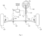
- FIG. 1 a schematic figure shows a control scheme over several control steps.
- a vehicle (480) with its several subsystems, has at every time a number of states, where a state is defined as a translational or rotational position, velocity or acceleration. These states are schematically represented by a dashed line (405).
- the vehicle (480) is equipped with a series of sensors (410) for direct or indirect measurements of the vehicle states.
- sensors can be used such as a torsion-bar torque sensor, a steering-wheel angle sensor, vehicle wheel speed sensors, a vehicle yaw rate sensor, a vehicle lateral acceleration sensor or a cluster of vehicle velocities and rotational speeds.
- the sensed or measured values of the vehicle states (405) are communicated to the control steps by the use of a signal bus (415), where a signal bus is a transmission path on which signals can be read and/or transmitted.
- a signal bus is a transmission path on which signals can be read and/or transmitted.
- the vehicle (480) there are two control paths (A, B) namely a vehicle state control path (A) indicated by (410)-(420)-(430)-(480) and a steering system assistance control path (B) indicated by (410)-(440)-(450)-(460)-(470)-(480).
- the vehicle state control path (A) contains a target vehicle state calculation (420), which is further illustrated in figure 2 , resulting in a target vehicle state.
- the target vehicle state calculation box (420) can be made such that a steering-wheel torque in figure 2 is a measure of a torque applied by the driver via a steering wheel compensated by a compensation torque.
- the steering-wheel torque contains several torque parts, namely the to the before-mentioned vehicle state related torque, but also a friction torque owing to the friction between the tyres and the road, a friction torque of the steering system owing to the friction of the parts of the linkage of the steering system, a damping torque owing to damping of the tyres and the steering system and a returnability torque that comes from the geometry of the steering system.
- This compensation torque is the sum of the above-mentioned tyre friction torque, the friction torque, the damping torque and the returnability torque.
- the parts of the compensation torque are calculated from mathematical models of the different torque parts.
- the mathematical model of the tyre friction torque is a model of an angle or angular speed driven hysteresis.
- the mathematical model of the tyre also contains a relaxation part such that as the tyre rolls, the torque of the hysteresis will have a relaxation length so that the hysteresis torque decreases with the rolling length of the tyre.
- the relaxation can preferably be the well-known half-life exponential decay function.
- the model of the tyre friction is the combination of the hysteresis and the relaxation so that e.g. an increase owing to the hysteresis torque can happen at the same time as the torque decrease owing to the relaxation.
- the resulting torque of the model is the sum of the two parts.
- the mathematical model of the friction torque is a model of an angle or angular speed driven hysteresis.
- the maximum torque in the hysteresis can be shaped by a function so that the maximum torque is different on centre compared to off centre.
- the mathematical model of the damping torque consists of a damping constant times an angular speed or translational speed, such as e.g. a rack velocity, measured somewhere in the linkage between the road wheels and the steering wheel.
- the damping constant can be such that the damping has a blow-off, such that the damping constant decreases for great angular or translational speeds.
- the damping constant can be vehicle speed dependent as well as different for steering outwards compared to inwards.
- the damping constant can also be a function of the steering-wheel or torsion-bar torque.
- the returnability torque is a vehicle speed dependent and steering-wheel angle dependent torque.
- a vehicle state controller (430) is defined as a dynamic function for achieving a target state in a vehicle (480) in a controlled manner.
- the vehicle state controller or controllers in the case of several controllers controlling several vehicle state actuators, are responsible for calculating target values for the vehicle state actuators in the vehicle (480).
- a vehicle state actuator is an actuator that when actuated influences one or several vehicle states. Vehicle state actuators are brakes, engine, controllable four-wheel-drive clutches, controllable differentials, active dampers, electric or hydraulic wheel motors and electrically or hydraulically driven axles.
- An actuator is a mechanism or system that is operated by an ECU and converts a source of energy, typically electric current, hydraulic fluid pressure, or pneumatic pressure, into a motion, force or torque.
- Controllability describes the ability of an external target value to move the internal state of a system from any initial state to any other final state in a finite time interval.
- a target value, reference value or request is a set point for the actuator, and a control error is the difference between the target value and the actual value, and the aim of the controller is to minimise this control error and hence achieving the target value in a controlled manner.
- the steering system assistance control path (B) consists of a vehicle model (440), which is a mathematical model that transforms a road-wheel angle and a vehicle speed to a number of vehicle yaw and/or lateral states, namely vehicle yaw rate and acceleration, vehicle lateral speed and acceleration and vehicle body sideslip angle.
- the states calculated in the vehicle model (440) are used in an understeer calculation (450), where understeer is defined as the situation where the vehicle steers less than the steering indicated by the vehicle model.
- the level of understeer calculated in the understeer calculation (450) is a transformation from the vehicle model states and the measured states to the level of understeer.
- a transformation is defined as a mathematical function or lookup table with one or more input values used to produce one or more output values.
- a ramp calculation there is a transformation between the level of understeer to a torque ramp (350, see Fig 3 ) value, which is an additional steering-wheel torque to be added to a base steering-wheel torque.
- a steering-wheel torque measurement is a torque measured in the steering column or steering wheel or a force measured in the steering rack times the torque ratio between the steering rack and the steering wheel.
- a base or normal steering-wheel torque is a torque that would occur without a torque ramp.
- the steering assistance is calculated so that the resulting steering-wheel torque is a sum of a base steering-wheel torque and an additional torque ramp.
- An additional torque can be added to a base torque by the use of a delta steering-wheel torque interface such that the assistance will result in the steering-wheel torque sum.
- a delta torque interface is for e.g. a boost curve control with a dual torque injection.
- the delta steering-wheel torque is added both before and after the boost curve, and hence, the boost curve is moved along a line with a gradient of minus one so that the delta steering-wheel torque shifts the equilibrium position.
- the level of assistance and the torque applied by the driver to the steering wheel will result in a steering-wheel angle (310), which will serve as an input to the behaviour of the vehicle (480).
- a steering-wheel angle is here referred to as any angle between the steering wheel and the road wheel times the ratio between the angular degree of freedom and the steering-wheel angular degree of freedom. It can also be a rack position times its ratio between the rack translational degree of freedom to the steering-wheel angular degree of freedom.
- a torque reference generator is a steering feel control concept where the steering-wheel torque is calculated in a reference generator, and this reference steering-wheel torque is then compared to a measured steering-wheel torque and the difference, the steering-wheel torque error, is fed to a controller so that this error is minimised.
- a third delta steering-wheel torque interface is the addition of a delta torque to the compensation torque value of an angle reference generator.
- An angle reference generator is a steering feel control concept where the steering-wheel angle is calculated in a reference generator, and this reference steering-wheel angle is then compared to a measured steering-wheel angle and the difference, the steering-wheel angle error, is fed to a controller so that this error is minimised.
- a schematic figure shows the relation between a vehicle yaw rate (210) on the abscissa and a steering-wheel torque (220) on the ordinate.
- a solid line (230) therein corresponds to a reference relation between the vehicle yaw rate and the steering-wheel torque.
- a dashed line (240) corresponds to how a steering-wheel torque is used to achieve a working point on the reference relation between the vehicle yaw rate and the steering-wheel torque.
- a dashed line (250) corresponds to how a working point on the reference relation between the vehicle yaw rate and the steering-wheel torque is used to achieve a target vehicle state, which in this figure is represented by a vehicle yaw rate.
- a steering-wheel torque is by the before-mentioned dashed line (250) transformed to a target yaw and/or lateral vehicle state.
- Figure 3 shows a schematic figure of the relation between a steering-wheel angle (310) on the abscissa and a steering-wheel torque (320) on the ordinate.
- a dashed line (330) in the figure corresponds to the situation where the tyre-to-road friction is not fully utilised, while a dash-dotted line (340) corresponds to the situation where the tyre-to-road friction is fully utilised, i.e. reaches its peak friction.
- the pneumatic trail which is the distance between the centre of the tyre-to-road contact and the resultant of the side force of the tyre, will decrease.
- the solid line corresponds to the situation where there is a ramp function (350) in the relation between the steering-wheel angle and the steering-wheel torque.
- a ramp function is a transformation between the level of understeer and the level of additional steering-wheel torque.
- FIG 4 is a schematic figure of a steering system (100).
- a power assisted steering system of a vehicle there is a linkage between the front axle road wheels (127) and the steering wheel (120).
- the linkage consists of a steering rack (124) with associated tie rods (125) connected via a pinion (122) to the steering column (121).
- the steering column (121) incorporates a torsion bar (128) with a torque sensor for measuring the steering torque applied by the driver.
- the assistance torque is actuated by a steering assistance actuator, which consists of an assistance motor (115) and an ECU (110).
- the control of the level of assistance actuation in the steering assistance actuator is controlled by a control system in the ECU.
- the present invention is based on the fact that the torque in the torsion bar (128), that is sensed by the sensors (410) and sent via the signal bus (415), is used and transformed in a series of steps according to figure 1 :
- the yaw torque should preferably be transformed to target brake torques of the rear axle only.
- the brake distribution between the two wheel brakes can be made in several ways, where one is to brake the inner rear wheel only, and another is to add a brake torque to the outer wheel as well in such a way that the target yaw torque is fulfilled. In the case of several rear axles, distribution between all of the rear axle brakes should be made.
- step 1 is in comparison to embodiment 1 altered in such a way that the steering-wheel torque in figure 2 is a measure of a torque applied by the driver via the steering wheel compensated by a compensation torque.
- This first step of the second embodiment is used together with the other steps from the first embodiment, whereby all steps necessary for the invention also in this embodiment is described, and again, the result of the invention is that the front axle tyre-to-road friction is fully utilised at the same time as the vehicle yaw and/or lateral vehicle states are controlled.
- step 3 is in comparison to embodiment 1 altered in such a way that the number of controllers is not limited to only one controller as depicted as (430) in Figure 1 .
- controllers e.g. one for every actuator used in the control of the vehicle stability, can be used.
- one controller for every vehicle state actuator is used.
- the vehicle state control error can either be used directly by rule based controllers or by first transforming it to a target vehicle yaw torque, to be used by the different controllers.
- This third step of the third embodiment can be used together with the full set of permutations of all of the other steps from all of the previously described embodiments, whereby all steps necessary for the invention also in this embodiment is fully described in all its combinations, and again, the result of the invention is that the front axle tyre-to-road friction is fully utilised at the same time as the vehicle yaw and/or lateral vehicle states are controlled.
- step 3 is in comparison to the first embodiment altered in such a way that several vehicle state actuators are used in combination with only one controller (430).
- the vehicle state control error is first transformed to a target vehicle yaw torque.
- This yaw torque is distributed to the different vehicle state actuators.
- the distribution can be made by the use of e.g. control allocation or any other control method for over-actuated systems.
- the vehicle state error is minimised by e.g. the control allocation controller.
- Over-actuated systems are systems with more actuators than degrees of freedom to be controlled.
- This third step of the third embodiment can be used together with the full set of permutations of all of the other steps from all of the previously described embodiments, whereby all steps necessary for the invention also in this embodiment is fully described in all its combinations, and again, the result of the invention is that the front axle tyre-to-road friction is fully utilised at the same time as the vehicle yaw and/or lateral vehicle states are controlled.
- step 5 is in comparison to the first embodiment altered in such a way that a, to a person skilled in the art well-known, two-track vehicle model (440) is used.
- a model is more advanced and includes among others lateral load transfer.
- load transfer is important in situations where the tire load capabilities is of importance, as they are at limit handling situation such as understeer.
- This fifth step of the fifth embodiment can be used together with the full set of permutations of all of the other steps from all of the other previously described embodiments, whereby all steps necessary for the invention also in this embodiment is fully described in all its combinations, and again, the result of the invention is that the front axle tyre-to-road friction is fully utilised at the same time as the vehicle yaw and/or lateral vehicle states are controlled.
- step 6 is altered in such a way that the level of understeer, in the understeer calculation (450), is the difference between the measured vehicle yaw and/or lateral vehicle state and the corresponding one calculated in the vehicle model times a vehicle velocity dependent weighting function.
- This sixth step of the sixth embodiment can be used together with the full set of permutations of all of the other steps from all the previously described embodiments, whereby all steps necessary for the invention also in this embodiment is fully described in all its combinations, and again, the result of the invention is that the front axle tyre-to-road friction is fully utilised at the same time as the vehicle yaw and/or lateral vehicle states are controlled.
- step 6 is altered in such a way that the level of understeer, in the understeer calculation (450), is a relative difference, such that it is calculated as the difference between the measured vehicle yaw and/or lateral vehicle state and the corresponding one calculated in the vehicle model divided by the corresponding measured or calculated one or a linear combination thereof.
- This sixth step of the seventh embodiment can be used together with the full set of permutations of all of the other steps from all of the previously described embodiments, whereby all steps necessary for the invention also in this embodiment is fully described in all its combinations, and again, the result of the invention is that the front axle tyre-to-road friction is fully utilised at the same time as the vehicle yaw and/or lateral vehicle states are controlled.
- step 7 is altered in such a way that the level of understeer is used in (460) for the transformation to the additional steering-wheel torque to be added to the base steering-wheel torque such that the ramp function is steering-wheel angle driven.
- the ramp function starts at a critical steering-wheel angle where the level of understeer is greater than a critical level of understeer and increases as a function of the difference between the current steering-wheel angle and the critical one.
- This seventh step of the eighth embodiment can be used together with the full set of permutations of all of the other steps from all of the previously described embodiments, whereby all steps necessary for the invention also in this embodiment is fully described in all its combinations, and again, the result of the invention is that the front axle tyre-to-road friction is fully utilised at the same time as the vehicle yaw and/or lateral vehicle states are controlled.
- step 7 is altered in such a way that the level of understeer is used in the ramp calculation (460) for the transformation to the additional steering-wheel torque to be added to the base steering-wheel torque such that the ramp function is a linear combination of a function of the level of understeer and a function that starts at the critical steering-wheel angle where the level of understeer is greater than a critical level of understeer and increases as a function of the difference between the current steering-wheel angle and the critical one.
- This seventh step of the ninth embodiment can be used together with the full set of permutations of all of the other steps from all of the previously described embodiments, whereby all steps necessary for the invention also in this embodiment is fully described in all its combinations, and again, the result of the invention is that the front axle tyre-to-road friction is fully utilised at the same time as the vehicle yaw and/or lateral vehicle states are controlled.
- step 8 is altered in such a way that the additional steering-wheel torque is in the steering assistance calculation (470) added to the steering-wheel reference torque of a torque reference generator.
- This eighth step of the tenth embodiment can be used together with the full set of permutations of all of the other steps from the previously described embodiments, whereby all steps necessary for the invention also in this embodiment is fully described in all its combinations, and again, the result of the invention is that the front axle tyre-to-road friction is fully utilised at the same time as the vehicle yaw and/or lateral vehicle states are controlled.
- step 8 is altered in such a way that the additional steering-wheel torque is in the steering assistance calculation (470) added to the compensation torque of an angle reference generator.
- This eighth step of the eleventh embodiment can be used together with the full set of permutations of all of the other steps from all of the earlier embodiments as previously described, whereby all steps necessary for the invention also in this embodiment is fully described in all its combinations, and again, the result of the invention is that the front axle tyre-to-road friction is fully utilised at the same time as the vehicle yaw and/or lateral vehicle states are controlled.
Landscapes
- Engineering & Computer Science (AREA)
- Transportation (AREA)
- Mechanical Engineering (AREA)
- Chemical & Material Sciences (AREA)
- Combustion & Propulsion (AREA)
- Automation & Control Theory (AREA)
- Physics & Mathematics (AREA)
- Mathematical Physics (AREA)
- Steering Control In Accordance With Driving Conditions (AREA)
Claims (14)
- Procédé de commande d'un actionneur d'assistance de direction dans un système de direction (100) d'un véhicule (480) et d'un ou plusieurs actionneurs commandables d'état de véhicule dudit véhicule où le système de direction présente un couple de base de volant de direction et où le véhicule est dans une situation de sous-virage intégrant les étapes de procédé suivantes :- de mesure d'au moins deux signaux d'entrée à l'aide de capteurs (410) (tels qu'un capteur de couple à barre de torsion, un capteur d'angle de volant de direction, des capteurs de vitesse de roue du véhicule et un capteur de vitesse de lacet du véhicule),- dans un calcul de sous-virage (450), de détermination à partir desdits signaux d'entrée d'un niveau de sous-virage,- à partir du niveau de sous-virage mentionné ci-dessus, dans un calcul de rampe (460), de détermination d'une rampe de couple de volant de direction,- à partir d'au moins l'un des signaux d'entrée précités, de détermination d'une mesure d'un couple appliqué par le conducteur via le volant de direction (120),ladite rampe de couple de volant de direction étant additionnée audit couple de volant de direction de base, ladite somme de couple de volant de direction étant utilisée comme signal de référence avec l'actionneur d'assistance de direction mentionné précédemment et empêchant ainsi un braquage excessif du conducteur,
caractérisé en ce que ledit couple déterminé appliqué par le conducteur via un volant de direction (120) est compensé par un couple de compensation, incluant une ou plusieurs des contributions de couple suivantes : couple de frottement du système de direction, couple de frottement de pneu, couple d'amortissement et couple d'auto-alignement du volant de direction, et en ce que ledit couple compensé est transformé en un état de lacet et/ou latéral cible du véhicule en utilisant une fonction de calcul dans un calcul d'état cible du véhicule (420), ledit état de lacet et/ou latéral cible du véhicule étant utilisé comme un signal de référence avec un ou plusieurs contrôleurs d'état du véhicule pour la commande mentionnée d'un ou plusieurs actionneurs d'état du véhicule afin de commander un trajet du véhicule, de sorte que le frottement pneu de l'essieu avant / route est complètement utilisé en même temps que les états de lacet et/ou latéral (/latéraux) du véhicule sont commandés. - Procédé selon la revendication 1, caractérisé en ce que le niveau de sous-virage dans le calcul de sous-virage (450) est la différence entre un état de lacet et/ou latéral du véhicule provenant des capteurs mentionnés ci-dessus (410) et/ou un état de lacet et/ou latéral calculé de véhicule provenant d'un modèle bicyclette.
- Procédé selon la revendication 1 ou 2, caractérisé en ce que les actionneurs commandables d'état du véhicule sont les freins du véhicule et en ce qu'un contrôleur de frein dans le contrôleur d'état du véhicule (430) agit sur l'état de lacet et/ou latéral cible mentionné du véhicule pour minimiser une différence entre l'état de lacet et/ou latéral mesuré du véhicule et l'état de lacet et/ou latéral cible du véhicule.
- Procédé selon l'une quelconque des revendications 1 à 3, caractérisé en ce que l'addition de la rampe de couple est réalisée par l'utilisation d'une interface de couple de volant de direction delta sous la forme d'une injection à double couple à un contrôleur de courbe de suralimentation.
- Procédé selon l'une quelconque des revendications 1, 2, ou 4 dépendant de la revendication 1 ou 2, caractérisé par le fait que plusieurs contrôleurs des actionneurs commandables d'état du véhicule sont, dans le contrôleur d'état de véhicule (430), utilisés de telle sorte qu'il y a un contrôleur pour chaque actionneur d'état du véhicule et que l'erreur de commande d'état du véhicule est soit directement utilisée par des contrôleurs basés sur des règles, soit d'abord transformée en un couple de lacet du véhicule cible, pour être utilisée par les contrôleurs.
- Procédé selon l'une quelconque des revendications 1 ou 2, ou 4 dépendant de la revendication 1 ou 2, caractérisé par le fait que plusieurs actionneurs d'état du véhicule sont utilisés en combinaison avec un seul contrôleur dans le contrôleur d'état du véhicule (430) où l'erreur de commande d'état du véhicule est d'abord transformée en un couple de lacet cible du véhicule et ensuite distribuée aux différents actionneurs d'état du véhicule par l'utilisation d'un procédé de commande pour systèmes sur-actionnés.
- Procédé selon la revendication 1 ou l'une quelconque des revendications 3-6 dépendant de la revendication 1, caractérisé par le fait que le niveau de sous-virage dans le calcul de sous-virage (450) est la différence entre l'état de lacet et/ou latéral mesuré du véhicule et l'état correspondant calculé dans un modèle de véhicule (440) fois une fonction de pondération dépendant de la vitesse du véhicule.
- Procédé selon la revendication 1 ou l'une quelconque des revendications 3 à 7 dépendant de la revendication 1, caractérisé par le fait que le niveau de sous-virage dans le calcul de sous-virage (450) est une différence relative entre l'état de lacet et/ou latéral mesuré du véhicule et l'état correspondant calculé dans le modèle de véhicule divisé par l'état mesuré ou calculé correspondant ou une combinaison linéaire de ceux-ci.
- Procédé selon l'une quelconque des revendications 1 à 8, caractérisé par le fait que la rampe est une fonction du niveau de sous-virage de telle sorte que la rampe dans le calcul de rampe (460) débute à un angle critique du volant de direction où le sous-virage est supérieur à une valeur de seuil prédéterminée du véhicule réel et également et aussi de sorte que la rampe est une fonction de la différence entre l'angle actuel du volant de direction et l'angle critique.
- Procédé selon l'une quelconque des revendications 1 à 8, caractérisé par le fait que le niveau de sous-virage est utilisé dans le calcul de rampe (460) dans un calcul de la fonction de rampe pour le transformation vers le couple additionnel du volant de direction à ajouter au couple de base de volant de direction de manière à ce que la fonction de rampe soit une combinaison linéaire d'une fonction du niveau de sous-virage et d'une fonction de rampe qui commence à l'angle critique du volant de direction où le niveau de sous-virage est supérieur à un niveau critique de sous-virage et augmente en fonction de la différence entre l'angle actuel du volant de direction et l'angle critique.
- Procédé selon l'une quelconque des revendications 1 ou 2, ou l'une quelconque des revendications 4 à 10 dépendant de la revendication 1 ou 2, caractérisé par le fait que le couple additionnel du volant de direction, dans le calcul d'assistance de direction (470), est ajouté au couple de référence du volant de direction d'un générateur de référence de couple.
- Procédé selon l'une quelconque des revendications 1 ou 2, ou l'une quelconque des revendications 4 à 10 dépendant de la revendication 1 ou 2, caractérisé par le fait que le couple additionnel du volant de direction, dans le calcul d'assistance de direction (470), est ajouté au couple de compensation d'un générateur de référence d'angle.
- Procédé selon l'une quelconque des revendications 1 ou 3, ou l'une quelconque des revendications 1-12 dépendant de la revendication 1 ou 2, caractérisé par le fait que le niveau de sous-virage dans le calcul de sous-virage (450) est la différence entre l'état de lacet et/ou latéral détecté du véhicule et un état de lacet et/ou latéral calculé de véhicule provenant d'un modèle de véhicule à deux voies.
- Procédé selon l'une quelconque des revendications précédentes, caractérisé par le fait que les étapes qui y sont comprises sont réalisées sous la forme d'un logiciel programmable.
Applications Claiming Priority (2)
| Application Number | Priority Date | Filing Date | Title |
|---|---|---|---|
| SE1300652 | 2013-10-16 | ||
| PCT/SE2014/051218 WO2015057147A1 (fr) | 2013-10-16 | 2014-10-15 | Procédé de commande de comportement de véhicule |
Publications (2)
| Publication Number | Publication Date |
|---|---|
| EP3057848A1 EP3057848A1 (fr) | 2016-08-24 |
| EP3057848B1 true EP3057848B1 (fr) | 2018-04-11 |
Family
ID=51869012
Family Applications (1)
| Application Number | Title | Priority Date | Filing Date |
|---|---|---|---|
| EP14795881.3A Active EP3057848B1 (fr) | 2013-10-16 | 2014-10-15 | Procédé de commande de comportement de véhicule |
Country Status (3)
| Country | Link |
|---|---|
| US (1) | US10005455B2 (fr) |
| EP (1) | EP3057848B1 (fr) |
| WO (1) | WO2015057147A1 (fr) |
Families Citing this family (34)
| Publication number | Priority date | Publication date | Assignee | Title |
|---|---|---|---|---|
| JP6384733B2 (ja) * | 2015-11-20 | 2018-09-05 | 本田技研工業株式会社 | 通信システム、及び制御装置 |
| ES2772749T3 (es) * | 2016-02-05 | 2020-07-08 | Sentient Ip Ab | Procedimiento para el control de la dirección y el comportamiento de un vehículo |
| DE102017103034B4 (de) * | 2016-02-16 | 2022-02-10 | Steering Solutions Ip Holding Corporation | Lenkungssystem zum Detektieren von Bewegungszuständen eines Fahrzeugs |
| DE102016214925A1 (de) * | 2016-08-11 | 2018-02-15 | Robert Bosch Gmbh | Verfahren und Vorrichtung zum Betreiben eines Kraftfahrzeugs, Kraftfahrzeug |
| JP6663333B2 (ja) * | 2016-09-23 | 2020-03-11 | 株式会社Subaru | 車両の制御装置及び車両の制御方法 |
| WO2018105399A1 (fr) * | 2016-12-09 | 2018-06-14 | 日立オートモティブシステムズ株式会社 | Appareil d'estimation d'état de mouvement de véhicule |
| EP3360757B1 (fr) * | 2017-02-10 | 2019-10-02 | Volvo Car Corporation | Gestionnaire de couple de braquage avancé destiné à un système d'aide au conducteur d'un véhicule routier |
| JP6787174B2 (ja) * | 2017-02-22 | 2020-11-18 | トヨタ自動車株式会社 | 駆動力制御装置 |
| EP3375696B1 (fr) * | 2017-03-17 | 2019-11-20 | Volvo Car Corporation | Gestionnaire de couple de braquage destinés à un système d'aide au conducteur d'un véhicule routier |
| EP3378733B1 (fr) * | 2017-03-20 | 2020-01-15 | Volvo Car Corporation | Appareil et procédé de commande d'angle de roue en fonction de la situation (had ou adas) |
| EP3378731B1 (fr) | 2017-03-20 | 2020-01-15 | Volvo Car Corporation | Appareil et procédé de commande d'angle de roue fonction de l'activité du conducteur (adas) |
| KR102335528B1 (ko) * | 2017-06-08 | 2021-12-03 | 현대자동차주식회사 | 타이어 파열 감지 및 긴급 조향 어시스트 시스템 및 방법 |
| EP3413082B1 (fr) | 2017-06-09 | 2020-01-01 | Veoneer Sweden AB | Système de véhicule pour la détection de véhicules en approche |
| US10800443B2 (en) | 2017-09-21 | 2020-10-13 | Steering Solutions Ip Holding Corporation | Catch motor torque generation in steer by wire system |
| SE541795C2 (en) * | 2017-09-22 | 2019-12-17 | Sentient Ip Ab | Method and system for controlling vehicle lane holding |
| US10752287B2 (en) * | 2017-10-03 | 2020-08-25 | Toyota Jidosha Kabushiki Kaisha | Steer-by-wire system |
| CN109774783B (zh) * | 2017-11-10 | 2022-05-13 | 现代自动车株式会社 | 用于电动转向的控制方法和控制系统 |
| US10375290B2 (en) * | 2017-11-20 | 2019-08-06 | Ross Video Limited | Video equipment control |
| US11377140B2 (en) | 2017-12-07 | 2022-07-05 | Steering Solutions Ip Holding Corporation | Notification for rack limiting conditions for steer by wire steering systems |
| US10906581B2 (en) | 2017-12-07 | 2021-02-02 | Steering Solutions Ip Holding Corporation | Rack-limiting condition detection and the corresponding steering wheel torque feedback for steer by wire steering systems |
| CN108944866B (zh) * | 2018-07-06 | 2021-06-01 | 长春工业大学 | 一种改善转向与制动协同控制的自适应模型预测控制算法 |
| CN109050658B (zh) * | 2018-07-06 | 2020-09-18 | 长春工业大学 | 基于模型预测控制的汽车主动前轮转向自适应调节方法 |
| JP7185219B2 (ja) * | 2018-09-10 | 2022-12-07 | マツダ株式会社 | 車両の制御方法、車両システム及び車両の制御装置 |
| ES2963510T3 (es) * | 2018-09-18 | 2024-03-27 | Volvo Car Corp | Método y sistema para evitar colisiones |
| DE102018124866A1 (de) * | 2018-10-09 | 2020-04-09 | Schaeffler Technologies AG & Co. KG | Verfahren zur Ermittlung eines Fahrbahnzustandes und Fahrzeug mit mindestens zwei radselektiven Lenkungsaktuatoren |
| CN110562318B (zh) * | 2018-11-26 | 2021-09-28 | 长城汽车股份有限公司 | 用于车辆的辅助控制系统及方法 |
| SE543719C2 (en) * | 2018-11-28 | 2021-06-29 | Sentient Ip Ab | A power assisted steering system arrangement |
| CN111824049B (zh) * | 2019-04-15 | 2022-07-15 | 比亚迪股份有限公司 | 车辆爆胎的控制方法、装置和车辆 |
| CN111661140B (zh) * | 2020-01-09 | 2021-06-11 | 吉林大学 | 一种电动助力转向系统助力特性表计算方法 |
| CN112026911B (zh) * | 2020-08-28 | 2022-04-29 | 北京汽车股份有限公司 | 转向助力的补偿方法、补偿装置和车辆 |
| US11724733B2 (en) * | 2020-09-23 | 2023-08-15 | Steering Solutions Ip Holding Corporation | Torque-based directional control in steer-by-wire steering systems |
| US11872989B2 (en) * | 2020-12-18 | 2024-01-16 | GM Global Technology Operations LLC | Method and system for controlling vehicle operation |
| CN115042855B (zh) * | 2021-09-16 | 2024-06-14 | 长城汽车股份有限公司 | 一种辅助驾驶方法、中央控制器及车辆 |
| CN118541301A (zh) * | 2022-09-26 | 2024-08-23 | 宁德时代新能源科技股份有限公司 | 车辆的控制方法及相关装置 |
Family Cites Families (1)
| Publication number | Priority date | Publication date | Assignee | Title |
|---|---|---|---|---|
| EP2112053B1 (fr) | 2008-04-25 | 2015-08-12 | Volvo Car Corporation | Système de contrôle de la stabilité de lacet |
-
2014
- 2014-10-15 WO PCT/SE2014/051218 patent/WO2015057147A1/fr active Application Filing
- 2014-10-15 EP EP14795881.3A patent/EP3057848B1/fr active Active
- 2014-10-15 US US15/029,435 patent/US10005455B2/en active Active
Also Published As
| Publication number | Publication date |
|---|---|
| US10005455B2 (en) | 2018-06-26 |
| EP3057848A1 (fr) | 2016-08-24 |
| WO2015057147A1 (fr) | 2015-04-23 |
| US20160272197A1 (en) | 2016-09-22 |
Similar Documents
| Publication | Publication Date | Title |
|---|---|---|
| EP3057848B1 (fr) | Procédé de commande de comportement de véhicule | |
| EP3684676B1 (fr) | Procédé et méthode pour garder un véhicule sur sa voie | |
| US8244435B2 (en) | Method and system for determining an optimal steering angle in understeer situations in a vehicle | |
| EP2112053B1 (fr) | Système de contrôle de la stabilité de lacet | |
| US9020699B2 (en) | Method and braking system for influencing driving dynamics by means of braking and driving operations | |
| US8983748B2 (en) | Vehicle dynamics control device | |
| US7171296B2 (en) | Integrated control apparatus for vehicle | |
| US9014921B2 (en) | Method and system for regulating driving stability | |
| US7997373B2 (en) | Steering control device for vehicle | |
| US20100191423A1 (en) | Vehicle rollover prevention control apparatus and vehicle rollover prevention control method | |
| CN103118911B (zh) | 车辆行驶控制装置 | |
| US20180178769A1 (en) | Method for assisting drivers in the event of aquaplaning on a road surface | |
| US8255122B2 (en) | Vehicle behavior control apparatus | |
| US7775608B2 (en) | Method for controlling a brake pressure | |
| JP2022515308A (ja) | 車両を所望の曲線経路に追従させる方法 | |
| JP4172361B2 (ja) | 電動式パワーステアリング装置用制御装置 | |
| US8442736B2 (en) | System for enhancing cornering performance of a vehicle controlled by a safety system | |
| JP4284210B2 (ja) | 車両の操舵制御装置 | |
| Wang et al. | Coordinated control of differential drive assisted steering system with vehicle stability enhancement system | |
| JP4685407B2 (ja) | 車輌の挙動制御装置 | |
| Lee et al. | Steering assist torque control enhancing vehicle stabiliity | |
| JP2009269573A (ja) | 車両挙動制御装置 |
Legal Events
| Date | Code | Title | Description |
|---|---|---|---|
| PUAI | Public reference made under article 153(3) epc to a published international application that has entered the european phase |
Free format text: ORIGINAL CODE: 0009012 |
|
| 17P | Request for examination filed |
Effective date: 20160426 |
|
| AK | Designated contracting states |
Kind code of ref document: A1 Designated state(s): AL AT BE BG CH CY CZ DE DK EE ES FI FR GB GR HR HU IE IS IT LI LT LU LV MC MK MT NL NO PL PT RO RS SE SI SK SM TR |
|
| AX | Request for extension of the european patent |
Extension state: BA ME |
|
| DAX | Request for extension of the european patent (deleted) | ||
| 17Q | First examination report despatched |
Effective date: 20170309 |
|
| GRAJ | Information related to disapproval of communication of intention to grant by the applicant or resumption of examination proceedings by the epo deleted |
Free format text: ORIGINAL CODE: EPIDOSDIGR1 |
|
| GRAP | Despatch of communication of intention to grant a patent |
Free format text: ORIGINAL CODE: EPIDOSNIGR1 |
|
| INTG | Intention to grant announced |
Effective date: 20171122 |
|
| RAP1 | Party data changed (applicant data changed or rights of an application transferred) |
Owner name: SENTIENT SWEDEN EKONOMISK FOERENING |
|
| RIN1 | Information on inventor provided before grant (corrected) |
Inventor name: POHL, JOCHEN Inventor name: HULTEN, JOHAN |
|
| RAP1 | Party data changed (applicant data changed or rights of an application transferred) |
Owner name: SENTIENT AB |
|
| GRAJ | Information related to disapproval of communication of intention to grant by the applicant or resumption of examination proceedings by the epo deleted |
Free format text: ORIGINAL CODE: EPIDOSDIGR1 |
|
| GRAR | Information related to intention to grant a patent recorded |
Free format text: ORIGINAL CODE: EPIDOSNIGR71 |
|
| GRAS | Grant fee paid |
Free format text: ORIGINAL CODE: EPIDOSNIGR3 |
|
| GRAA | (expected) grant |
Free format text: ORIGINAL CODE: 0009210 |
|
| INTG | Intention to grant announced |
Effective date: 20180228 |
|
| AK | Designated contracting states |
Kind code of ref document: B1 Designated state(s): AL AT BE BG CH CY CZ DE DK EE ES FI FR GB GR HR HU IE IS IT LI LT LU LV MC MK MT NL NO PL PT RO RS SE SI SK SM TR |
|
| REG | Reference to a national code |
Ref country code: GB Ref legal event code: FG4D |
|
| REG | Reference to a national code |
Ref country code: CH Ref legal event code: EP |
|
| REG | Reference to a national code |
Ref country code: AT Ref legal event code: REF Ref document number: 987712 Country of ref document: AT Kind code of ref document: T Effective date: 20180415 |
|
| REG | Reference to a national code |
Ref country code: IE Ref legal event code: FG4D |
|
| REG | Reference to a national code |
Ref country code: DE Ref legal event code: R096 Ref document number: 602014023839 Country of ref document: DE |
|
| REG | Reference to a national code |
Ref country code: SE Ref legal event code: TRGR |
|
| REG | Reference to a national code |
Ref country code: NL Ref legal event code: MP Effective date: 20180411 |
|
| REG | Reference to a national code |
Ref country code: LT Ref legal event code: MG4D |
|
| PG25 | Lapsed in a contracting state [announced via postgrant information from national office to epo] |
Ref country code: NL Free format text: LAPSE BECAUSE OF FAILURE TO SUBMIT A TRANSLATION OF THE DESCRIPTION OR TO PAY THE FEE WITHIN THE PRESCRIBED TIME-LIMIT Effective date: 20180411 |
|
| REG | Reference to a national code |
Ref country code: FR Ref legal event code: PLFP Year of fee payment: 5 |
|
| PG25 | Lapsed in a contracting state [announced via postgrant information from national office to epo] |
Ref country code: ES Free format text: LAPSE BECAUSE OF FAILURE TO SUBMIT A TRANSLATION OF THE DESCRIPTION OR TO PAY THE FEE WITHIN THE PRESCRIBED TIME-LIMIT Effective date: 20180411 Ref country code: PL Free format text: LAPSE BECAUSE OF FAILURE TO SUBMIT A TRANSLATION OF THE DESCRIPTION OR TO PAY THE FEE WITHIN THE PRESCRIBED TIME-LIMIT Effective date: 20180411 Ref country code: LT Free format text: LAPSE BECAUSE OF FAILURE TO SUBMIT A TRANSLATION OF THE DESCRIPTION OR TO PAY THE FEE WITHIN THE PRESCRIBED TIME-LIMIT Effective date: 20180411 Ref country code: BG Free format text: LAPSE BECAUSE OF FAILURE TO SUBMIT A TRANSLATION OF THE DESCRIPTION OR TO PAY THE FEE WITHIN THE PRESCRIBED TIME-LIMIT Effective date: 20180711 Ref country code: AL Free format text: LAPSE BECAUSE OF FAILURE TO SUBMIT A TRANSLATION OF THE DESCRIPTION OR TO PAY THE FEE WITHIN THE PRESCRIBED TIME-LIMIT Effective date: 20180411 Ref country code: FI Free format text: LAPSE BECAUSE OF FAILURE TO SUBMIT A TRANSLATION OF THE DESCRIPTION OR TO PAY THE FEE WITHIN THE PRESCRIBED TIME-LIMIT Effective date: 20180411 Ref country code: NO Free format text: LAPSE BECAUSE OF FAILURE TO SUBMIT A TRANSLATION OF THE DESCRIPTION OR TO PAY THE FEE WITHIN THE PRESCRIBED TIME-LIMIT Effective date: 20180711 |
|
| PG25 | Lapsed in a contracting state [announced via postgrant information from national office to epo] |
Ref country code: GR Free format text: LAPSE BECAUSE OF FAILURE TO SUBMIT A TRANSLATION OF THE DESCRIPTION OR TO PAY THE FEE WITHIN THE PRESCRIBED TIME-LIMIT Effective date: 20180712 Ref country code: LV Free format text: LAPSE BECAUSE OF FAILURE TO SUBMIT A TRANSLATION OF THE DESCRIPTION OR TO PAY THE FEE WITHIN THE PRESCRIBED TIME-LIMIT Effective date: 20180411 Ref country code: HR Free format text: LAPSE BECAUSE OF FAILURE TO SUBMIT A TRANSLATION OF THE DESCRIPTION OR TO PAY THE FEE WITHIN THE PRESCRIBED TIME-LIMIT Effective date: 20180411 Ref country code: RS Free format text: LAPSE BECAUSE OF FAILURE TO SUBMIT A TRANSLATION OF THE DESCRIPTION OR TO PAY THE FEE WITHIN THE PRESCRIBED TIME-LIMIT Effective date: 20180411 |
|
| REG | Reference to a national code |
Ref country code: AT Ref legal event code: MK05 Ref document number: 987712 Country of ref document: AT Kind code of ref document: T Effective date: 20180411 |
|
| PG25 | Lapsed in a contracting state [announced via postgrant information from national office to epo] |
Ref country code: PT Free format text: LAPSE BECAUSE OF FAILURE TO SUBMIT A TRANSLATION OF THE DESCRIPTION OR TO PAY THE FEE WITHIN THE PRESCRIBED TIME-LIMIT Effective date: 20180813 |
|
| REG | Reference to a national code |
Ref country code: DE Ref legal event code: R097 Ref document number: 602014023839 Country of ref document: DE |
|
| PG25 | Lapsed in a contracting state [announced via postgrant information from national office to epo] |
Ref country code: CZ Free format text: LAPSE BECAUSE OF FAILURE TO SUBMIT A TRANSLATION OF THE DESCRIPTION OR TO PAY THE FEE WITHIN THE PRESCRIBED TIME-LIMIT Effective date: 20180411 Ref country code: SK Free format text: LAPSE BECAUSE OF FAILURE TO SUBMIT A TRANSLATION OF THE DESCRIPTION OR TO PAY THE FEE WITHIN THE PRESCRIBED TIME-LIMIT Effective date: 20180411 Ref country code: RO Free format text: LAPSE BECAUSE OF FAILURE TO SUBMIT A TRANSLATION OF THE DESCRIPTION OR TO PAY THE FEE WITHIN THE PRESCRIBED TIME-LIMIT Effective date: 20180411 Ref country code: DK Free format text: LAPSE BECAUSE OF FAILURE TO SUBMIT A TRANSLATION OF THE DESCRIPTION OR TO PAY THE FEE WITHIN THE PRESCRIBED TIME-LIMIT Effective date: 20180411 Ref country code: AT Free format text: LAPSE BECAUSE OF FAILURE TO SUBMIT A TRANSLATION OF THE DESCRIPTION OR TO PAY THE FEE WITHIN THE PRESCRIBED TIME-LIMIT Effective date: 20180411 Ref country code: EE Free format text: LAPSE BECAUSE OF FAILURE TO SUBMIT A TRANSLATION OF THE DESCRIPTION OR TO PAY THE FEE WITHIN THE PRESCRIBED TIME-LIMIT Effective date: 20180411 |
|
| PLBE | No opposition filed within time limit |
Free format text: ORIGINAL CODE: 0009261 |
|
| STAA | Information on the status of an ep patent application or granted ep patent |
Free format text: STATUS: NO OPPOSITION FILED WITHIN TIME LIMIT |
|
| PG25 | Lapsed in a contracting state [announced via postgrant information from national office to epo] |
Ref country code: SM Free format text: LAPSE BECAUSE OF FAILURE TO SUBMIT A TRANSLATION OF THE DESCRIPTION OR TO PAY THE FEE WITHIN THE PRESCRIBED TIME-LIMIT Effective date: 20180411 Ref country code: IT Free format text: LAPSE BECAUSE OF FAILURE TO SUBMIT A TRANSLATION OF THE DESCRIPTION OR TO PAY THE FEE WITHIN THE PRESCRIBED TIME-LIMIT Effective date: 20180411 |
|
| 26N | No opposition filed |
Effective date: 20190114 |
|
| PG25 | Lapsed in a contracting state [announced via postgrant information from national office to epo] |
Ref country code: SI Free format text: LAPSE BECAUSE OF FAILURE TO SUBMIT A TRANSLATION OF THE DESCRIPTION OR TO PAY THE FEE WITHIN THE PRESCRIBED TIME-LIMIT Effective date: 20180411 |
|
| REG | Reference to a national code |
Ref country code: CH Ref legal event code: PL |
|
| REG | Reference to a national code |
Ref country code: BE Ref legal event code: MM Effective date: 20181031 |
|
| PG25 | Lapsed in a contracting state [announced via postgrant information from national office to epo] |
Ref country code: MC Free format text: LAPSE BECAUSE OF FAILURE TO SUBMIT A TRANSLATION OF THE DESCRIPTION OR TO PAY THE FEE WITHIN THE PRESCRIBED TIME-LIMIT Effective date: 20180411 Ref country code: LU Free format text: LAPSE BECAUSE OF NON-PAYMENT OF DUE FEES Effective date: 20181015 |
|
| REG | Reference to a national code |
Ref country code: IE Ref legal event code: MM4A |
|
| PG25 | Lapsed in a contracting state [announced via postgrant information from national office to epo] |
Ref country code: BE Free format text: LAPSE BECAUSE OF NON-PAYMENT OF DUE FEES Effective date: 20181031 Ref country code: CH Free format text: LAPSE BECAUSE OF NON-PAYMENT OF DUE FEES Effective date: 20181031 Ref country code: LI Free format text: LAPSE BECAUSE OF NON-PAYMENT OF DUE FEES Effective date: 20181031 |
|
| REG | Reference to a national code |
Ref country code: DE Ref legal event code: R081 Ref document number: 602014023839 Country of ref document: DE Owner name: SENTIENT IP AB, SE Free format text: FORMER OWNER: SENTIENT AB, GOETEBORG, SE |
|
| PG25 | Lapsed in a contracting state [announced via postgrant information from national office to epo] |
Ref country code: IE Free format text: LAPSE BECAUSE OF NON-PAYMENT OF DUE FEES Effective date: 20181015 |
|
| REG | Reference to a national code |
Ref country code: GB Ref legal event code: 732E Free format text: REGISTERED BETWEEN 20191031 AND 20191106 |
|
| PG25 | Lapsed in a contracting state [announced via postgrant information from national office to epo] |
Ref country code: MT Free format text: LAPSE BECAUSE OF NON-PAYMENT OF DUE FEES Effective date: 20181015 |
|
| PG25 | Lapsed in a contracting state [announced via postgrant information from national office to epo] |
Ref country code: TR Free format text: LAPSE BECAUSE OF FAILURE TO SUBMIT A TRANSLATION OF THE DESCRIPTION OR TO PAY THE FEE WITHIN THE PRESCRIBED TIME-LIMIT Effective date: 20180411 |
|
| PG25 | Lapsed in a contracting state [announced via postgrant information from national office to epo] |
Ref country code: HU Free format text: LAPSE BECAUSE OF FAILURE TO SUBMIT A TRANSLATION OF THE DESCRIPTION OR TO PAY THE FEE WITHIN THE PRESCRIBED TIME-LIMIT; INVALID AB INITIO Effective date: 20141015 Ref country code: CY Free format text: LAPSE BECAUSE OF FAILURE TO SUBMIT A TRANSLATION OF THE DESCRIPTION OR TO PAY THE FEE WITHIN THE PRESCRIBED TIME-LIMIT Effective date: 20180411 Ref country code: MK Free format text: LAPSE BECAUSE OF NON-PAYMENT OF DUE FEES Effective date: 20180411 |
|
| PG25 | Lapsed in a contracting state [announced via postgrant information from national office to epo] |
Ref country code: IS Free format text: LAPSE BECAUSE OF FAILURE TO SUBMIT A TRANSLATION OF THE DESCRIPTION OR TO PAY THE FEE WITHIN THE PRESCRIBED TIME-LIMIT Effective date: 20180811 |
|
| PGFP | Annual fee paid to national office [announced via postgrant information from national office to epo] |
Ref country code: GB Payment date: 20231018 Year of fee payment: 10 |
|
| PGFP | Annual fee paid to national office [announced via postgrant information from national office to epo] |
Ref country code: SE Payment date: 20231017 Year of fee payment: 10 Ref country code: FR Payment date: 20231016 Year of fee payment: 10 Ref country code: DE Payment date: 20231020 Year of fee payment: 10 |