EP3055120B1 - Procédé et dispositif pour la production d'un récipient rempli de matière de remplissage - Google Patents
Procédé et dispositif pour la production d'un récipient rempli de matière de remplissage Download PDFInfo
- Publication number
- EP3055120B1 EP3055120B1 EP15712525.3A EP15712525A EP3055120B1 EP 3055120 B1 EP3055120 B1 EP 3055120B1 EP 15712525 A EP15712525 A EP 15712525A EP 3055120 B1 EP3055120 B1 EP 3055120B1
- Authority
- EP
- European Patent Office
- Prior art keywords
- preform
- blowing
- container
- feed line
- inner cavity
- Prior art date
- Legal status (The legal status is an assumption and is not a legal conclusion. Google has not performed a legal analysis and makes no representation as to the accuracy of the status listed.)
- Active
Links
- 238000000034 method Methods 0.000 title claims description 31
- 238000007664 blowing Methods 0.000 claims description 106
- 239000007789 gas Substances 0.000 claims description 40
- 239000012530 fluid Substances 0.000 claims description 22
- 230000008569 process Effects 0.000 claims description 20
- 239000007788 liquid Substances 0.000 claims description 13
- 238000004519 manufacturing process Methods 0.000 claims description 10
- 239000012815 thermoplastic material Substances 0.000 claims description 7
- CURLTUGMZLYLDI-UHFFFAOYSA-N Carbon dioxide Chemical compound O=C=O CURLTUGMZLYLDI-UHFFFAOYSA-N 0.000 claims description 6
- 238000000465 moulding Methods 0.000 claims description 5
- 238000007789 sealing Methods 0.000 claims description 5
- 230000001143 conditioned effect Effects 0.000 claims description 4
- 230000003750 conditioning effect Effects 0.000 claims description 4
- 229910002092 carbon dioxide Inorganic materials 0.000 claims description 3
- 239000001569 carbon dioxide Substances 0.000 claims description 3
- 238000002156 mixing Methods 0.000 claims description 3
- 239000000203 mixture Substances 0.000 claims description 2
- 239000000463 material Substances 0.000 description 26
- 238000010438 heat treatment Methods 0.000 description 18
- 238000001816 cooling Methods 0.000 description 12
- 238000012546 transfer Methods 0.000 description 9
- 239000012263 liquid product Substances 0.000 description 8
- 238000000071 blow moulding Methods 0.000 description 7
- 230000008901 benefit Effects 0.000 description 6
- 229920000139 polyethylene terephthalate Polymers 0.000 description 5
- 239000005020 polyethylene terephthalate Substances 0.000 description 5
- 238000009826 distribution Methods 0.000 description 4
- -1 polyethylene terephthalate Polymers 0.000 description 4
- 238000003763 carbonization Methods 0.000 description 3
- 238000011161 development Methods 0.000 description 3
- 230000018109 developmental process Effects 0.000 description 3
- 239000000047 product Substances 0.000 description 3
- 239000004743 Polypropylene Substances 0.000 description 2
- 239000000969 carrier Substances 0.000 description 2
- 239000003651 drinking water Substances 0.000 description 2
- 235000020188 drinking water Nutrition 0.000 description 2
- 229920001155 polypropylene Polymers 0.000 description 2
- 230000009471 action Effects 0.000 description 1
- 238000013459 approach Methods 0.000 description 1
- 235000013361 beverage Nutrition 0.000 description 1
- 230000015572 biosynthetic process Effects 0.000 description 1
- 238000010276 construction Methods 0.000 description 1
- 230000001419 dependent effect Effects 0.000 description 1
- 238000007599 discharging Methods 0.000 description 1
- 230000000694 effects Effects 0.000 description 1
- 239000000945 filler Substances 0.000 description 1
- 238000005429 filling process Methods 0.000 description 1
- 235000013305 food Nutrition 0.000 description 1
- 239000004033 plastic Substances 0.000 description 1
- 229920003023 plastic Polymers 0.000 description 1
- 239000011112 polyethylene naphthalate Substances 0.000 description 1
- 238000002360 preparation method Methods 0.000 description 1
- 238000003825 pressing Methods 0.000 description 1
- 238000004886 process control Methods 0.000 description 1
- 238000012545 processing Methods 0.000 description 1
- 238000003672 processing method Methods 0.000 description 1
- 230000005855 radiation Effects 0.000 description 1
- 230000004044 response Effects 0.000 description 1
- 238000007493 shaping process Methods 0.000 description 1
- 238000004904 shortening Methods 0.000 description 1
- 239000007787 solid Substances 0.000 description 1
- 238000005496 tempering Methods 0.000 description 1
- 230000007704 transition Effects 0.000 description 1
Images


Classifications
-
- B—PERFORMING OPERATIONS; TRANSPORTING
- B29—WORKING OF PLASTICS; WORKING OF SUBSTANCES IN A PLASTIC STATE IN GENERAL
- B29C—SHAPING OR JOINING OF PLASTICS; SHAPING OF MATERIAL IN A PLASTIC STATE, NOT OTHERWISE PROVIDED FOR; AFTER-TREATMENT OF THE SHAPED PRODUCTS, e.g. REPAIRING
- B29C49/00—Blow-moulding, i.e. blowing a preform or parison to a desired shape within a mould; Apparatus therefor
- B29C49/42—Component parts, details or accessories; Auxiliary operations
- B29C49/46—Component parts, details or accessories; Auxiliary operations characterised by using particular environment or blow fluids other than air
-
- B—PERFORMING OPERATIONS; TRANSPORTING
- B29—WORKING OF PLASTICS; WORKING OF SUBSTANCES IN A PLASTIC STATE IN GENERAL
- B29C—SHAPING OR JOINING OF PLASTICS; SHAPING OF MATERIAL IN A PLASTIC STATE, NOT OTHERWISE PROVIDED FOR; AFTER-TREATMENT OF THE SHAPED PRODUCTS, e.g. REPAIRING
- B29C49/00—Blow-moulding, i.e. blowing a preform or parison to a desired shape within a mould; Apparatus therefor
- B29C49/08—Biaxial stretching during blow-moulding
- B29C49/10—Biaxial stretching during blow-moulding using mechanical means for prestretching
- B29C49/12—Stretching rods
-
- B—PERFORMING OPERATIONS; TRANSPORTING
- B29—WORKING OF PLASTICS; WORKING OF SUBSTANCES IN A PLASTIC STATE IN GENERAL
- B29C—SHAPING OR JOINING OF PLASTICS; SHAPING OF MATERIAL IN A PLASTIC STATE, NOT OTHERWISE PROVIDED FOR; AFTER-TREATMENT OF THE SHAPED PRODUCTS, e.g. REPAIRING
- B29C49/00—Blow-moulding, i.e. blowing a preform or parison to a desired shape within a mould; Apparatus therefor
- B29C49/18—Blow-moulding, i.e. blowing a preform or parison to a desired shape within a mould; Apparatus therefor using several blowing steps
-
- B—PERFORMING OPERATIONS; TRANSPORTING
- B29—WORKING OF PLASTICS; WORKING OF SUBSTANCES IN A PLASTIC STATE IN GENERAL
- B29C—SHAPING OR JOINING OF PLASTICS; SHAPING OF MATERIAL IN A PLASTIC STATE, NOT OTHERWISE PROVIDED FOR; AFTER-TREATMENT OF THE SHAPED PRODUCTS, e.g. REPAIRING
- B29C49/00—Blow-moulding, i.e. blowing a preform or parison to a desired shape within a mould; Apparatus therefor
- B29C49/28—Blow-moulding apparatus
- B29C49/30—Blow-moulding apparatus having movable moulds or mould parts
- B29C49/36—Blow-moulding apparatus having movable moulds or mould parts rotatable about one axis
-
- B—PERFORMING OPERATIONS; TRANSPORTING
- B29—WORKING OF PLASTICS; WORKING OF SUBSTANCES IN A PLASTIC STATE IN GENERAL
- B29C—SHAPING OR JOINING OF PLASTICS; SHAPING OF MATERIAL IN A PLASTIC STATE, NOT OTHERWISE PROVIDED FOR; AFTER-TREATMENT OF THE SHAPED PRODUCTS, e.g. REPAIRING
- B29C49/00—Blow-moulding, i.e. blowing a preform or parison to a desired shape within a mould; Apparatus therefor
- B29C49/42—Component parts, details or accessories; Auxiliary operations
- B29C49/64—Heating or cooling preforms, parisons or blown articles
- B29C49/6409—Thermal conditioning of preforms
-
- B—PERFORMING OPERATIONS; TRANSPORTING
- B65—CONVEYING; PACKING; STORING; HANDLING THIN OR FILAMENTARY MATERIAL
- B65B—MACHINES, APPARATUS OR DEVICES FOR, OR METHODS OF, PACKAGING ARTICLES OR MATERIALS; UNPACKING
- B65B3/00—Packaging plastic material, semiliquids, liquids or mixed solids and liquids, in individual containers or receptacles, e.g. bags, sacks, boxes, cartons, cans, or jars
- B65B3/02—Machines characterised by the incorporation of means for making the containers or receptacles
- B65B3/022—Making containers by moulding of a thermoplastic material
-
- B—PERFORMING OPERATIONS; TRANSPORTING
- B29—WORKING OF PLASTICS; WORKING OF SUBSTANCES IN A PLASTIC STATE IN GENERAL
- B29C—SHAPING OR JOINING OF PLASTICS; SHAPING OF MATERIAL IN A PLASTIC STATE, NOT OTHERWISE PROVIDED FOR; AFTER-TREATMENT OF THE SHAPED PRODUCTS, e.g. REPAIRING
- B29C49/00—Blow-moulding, i.e. blowing a preform or parison to a desired shape within a mould; Apparatus therefor
- B29C49/42—Component parts, details or accessories; Auxiliary operations
- B29C49/46—Component parts, details or accessories; Auxiliary operations characterised by using particular environment or blow fluids other than air
- B29C2049/4602—Blowing fluids
- B29C2049/4626—Blowing fluids containing carbon dioxide
-
- B—PERFORMING OPERATIONS; TRANSPORTING
- B29—WORKING OF PLASTICS; WORKING OF SUBSTANCES IN A PLASTIC STATE IN GENERAL
- B29C—SHAPING OR JOINING OF PLASTICS; SHAPING OF MATERIAL IN A PLASTIC STATE, NOT OTHERWISE PROVIDED FOR; AFTER-TREATMENT OF THE SHAPED PRODUCTS, e.g. REPAIRING
- B29C49/00—Blow-moulding, i.e. blowing a preform or parison to a desired shape within a mould; Apparatus therefor
- B29C49/42—Component parts, details or accessories; Auxiliary operations
- B29C49/46—Component parts, details or accessories; Auxiliary operations characterised by using particular environment or blow fluids other than air
- B29C2049/4602—Blowing fluids
- B29C2049/465—Blowing fluids being incompressible
-
- B—PERFORMING OPERATIONS; TRANSPORTING
- B29—WORKING OF PLASTICS; WORKING OF SUBSTANCES IN A PLASTIC STATE IN GENERAL
- B29C—SHAPING OR JOINING OF PLASTICS; SHAPING OF MATERIAL IN A PLASTIC STATE, NOT OTHERWISE PROVIDED FOR; AFTER-TREATMENT OF THE SHAPED PRODUCTS, e.g. REPAIRING
- B29C49/00—Blow-moulding, i.e. blowing a preform or parison to a desired shape within a mould; Apparatus therefor
- B29C49/42—Component parts, details or accessories; Auxiliary operations
- B29C49/78—Measuring, controlling or regulating
- B29C49/783—Measuring, controlling or regulating blowing pressure
- B29C2049/7831—Measuring, controlling or regulating blowing pressure characterised by pressure values or ranges
-
- B—PERFORMING OPERATIONS; TRANSPORTING
- B29—WORKING OF PLASTICS; WORKING OF SUBSTANCES IN A PLASTIC STATE IN GENERAL
- B29C—SHAPING OR JOINING OF PLASTICS; SHAPING OF MATERIAL IN A PLASTIC STATE, NOT OTHERWISE PROVIDED FOR; AFTER-TREATMENT OF THE SHAPED PRODUCTS, e.g. REPAIRING
- B29C49/00—Blow-moulding, i.e. blowing a preform or parison to a desired shape within a mould; Apparatus therefor
- B29C49/42—Component parts, details or accessories; Auxiliary operations
- B29C49/78—Measuring, controlling or regulating
- B29C49/783—Measuring, controlling or regulating blowing pressure
- B29C2049/7832—Blowing with two or more pressure levels
-
- B—PERFORMING OPERATIONS; TRANSPORTING
- B29—WORKING OF PLASTICS; WORKING OF SUBSTANCES IN A PLASTIC STATE IN GENERAL
- B29C—SHAPING OR JOINING OF PLASTICS; SHAPING OF MATERIAL IN A PLASTIC STATE, NOT OTHERWISE PROVIDED FOR; AFTER-TREATMENT OF THE SHAPED PRODUCTS, e.g. REPAIRING
- B29C2949/00—Indexing scheme relating to blow-moulding
- B29C2949/07—Preforms or parisons characterised by their configuration
- B29C2949/0715—Preforms or parisons characterised by their configuration the preform having one end closed
-
- B—PERFORMING OPERATIONS; TRANSPORTING
- B29—WORKING OF PLASTICS; WORKING OF SUBSTANCES IN A PLASTIC STATE IN GENERAL
- B29C—SHAPING OR JOINING OF PLASTICS; SHAPING OF MATERIAL IN A PLASTIC STATE, NOT OTHERWISE PROVIDED FOR; AFTER-TREATMENT OF THE SHAPED PRODUCTS, e.g. REPAIRING
- B29C49/00—Blow-moulding, i.e. blowing a preform or parison to a desired shape within a mould; Apparatus therefor
- B29C49/02—Combined blow-moulding and manufacture of the preform or the parison
- B29C49/06—Injection blow-moulding
-
- B—PERFORMING OPERATIONS; TRANSPORTING
- B29—WORKING OF PLASTICS; WORKING OF SUBSTANCES IN A PLASTIC STATE IN GENERAL
- B29C—SHAPING OR JOINING OF PLASTICS; SHAPING OF MATERIAL IN A PLASTIC STATE, NOT OTHERWISE PROVIDED FOR; AFTER-TREATMENT OF THE SHAPED PRODUCTS, e.g. REPAIRING
- B29C49/00—Blow-moulding, i.e. blowing a preform or parison to a desired shape within a mould; Apparatus therefor
- B29C49/08—Biaxial stretching during blow-moulding
- B29C49/10—Biaxial stretching during blow-moulding using mechanical means for prestretching
- B29C49/12—Stretching rods
- B29C49/121—Stretching rod configuration, e.g. geometry; Stretching rod material
- B29C49/1212—Stretching rod configuration, e.g. geometry; Stretching rod material the stretching rod comprising at least one opening on the surface, e.g. through which compressed air is blown into the preform to expand the same
-
- B—PERFORMING OPERATIONS; TRANSPORTING
- B29—WORKING OF PLASTICS; WORKING OF SUBSTANCES IN A PLASTIC STATE IN GENERAL
- B29C—SHAPING OR JOINING OF PLASTICS; SHAPING OF MATERIAL IN A PLASTIC STATE, NOT OTHERWISE PROVIDED FOR; AFTER-TREATMENT OF THE SHAPED PRODUCTS, e.g. REPAIRING
- B29C49/00—Blow-moulding, i.e. blowing a preform or parison to a desired shape within a mould; Apparatus therefor
- B29C49/08—Biaxial stretching during blow-moulding
- B29C49/10—Biaxial stretching during blow-moulding using mechanical means for prestretching
- B29C49/122—Drive means therefor
- B29C49/1222—Pneumatic
-
- B—PERFORMING OPERATIONS; TRANSPORTING
- B29—WORKING OF PLASTICS; WORKING OF SUBSTANCES IN A PLASTIC STATE IN GENERAL
- B29C—SHAPING OR JOINING OF PLASTICS; SHAPING OF MATERIAL IN A PLASTIC STATE, NOT OTHERWISE PROVIDED FOR; AFTER-TREATMENT OF THE SHAPED PRODUCTS, e.g. REPAIRING
- B29C49/00—Blow-moulding, i.e. blowing a preform or parison to a desired shape within a mould; Apparatus therefor
- B29C49/08—Biaxial stretching during blow-moulding
- B29C49/10—Biaxial stretching during blow-moulding using mechanical means for prestretching
- B29C49/122—Drive means therefor
- B29C49/1229—Drive means therefor being a cam mechanism
-
- B—PERFORMING OPERATIONS; TRANSPORTING
- B29—WORKING OF PLASTICS; WORKING OF SUBSTANCES IN A PLASTIC STATE IN GENERAL
- B29C—SHAPING OR JOINING OF PLASTICS; SHAPING OF MATERIAL IN A PLASTIC STATE, NOT OTHERWISE PROVIDED FOR; AFTER-TREATMENT OF THE SHAPED PRODUCTS, e.g. REPAIRING
- B29C49/00—Blow-moulding, i.e. blowing a preform or parison to a desired shape within a mould; Apparatus therefor
- B29C49/42—Component parts, details or accessories; Auxiliary operations
- B29C49/64—Heating or cooling preforms, parisons or blown articles
-
- B—PERFORMING OPERATIONS; TRANSPORTING
- B29—WORKING OF PLASTICS; WORKING OF SUBSTANCES IN A PLASTIC STATE IN GENERAL
- B29K—INDEXING SCHEME ASSOCIATED WITH SUBCLASSES B29B, B29C OR B29D, RELATING TO MOULDING MATERIALS OR TO MATERIALS FOR MOULDS, REINFORCEMENTS, FILLERS OR PREFORMED PARTS, e.g. INSERTS
- B29K2067/00—Use of polyesters or derivatives thereof, as moulding material
- B29K2067/003—PET, i.e. poylethylene terephthalate
-
- B—PERFORMING OPERATIONS; TRANSPORTING
- B29—WORKING OF PLASTICS; WORKING OF SUBSTANCES IN A PLASTIC STATE IN GENERAL
- B29L—INDEXING SCHEME ASSOCIATED WITH SUBCLASS B29C, RELATING TO PARTICULAR ARTICLES
- B29L2031/00—Other particular articles
- B29L2031/712—Containers; Packaging elements or accessories, Packages
- B29L2031/7158—Bottles
Definitions
- the invention relates to a method for producing a container filled with a liquid product, wherein a preform made of a thermoplastic material is stretched after a thermal conditioning by means of a stretching rod and formed in an inflation process in the container, wherein the inflation process comprises a Vorblasphase, in the a fluid of a first pressure level is used for inflation, and a main inflation phase in which a fluid of a second pressure level higher than the first pressure level is used for inflation.
- the invention further relates to a device for producing a container filled with a liquid product comprising a heating device for the thermal conditioning of preforms made of a thermoplastic material, and comprising a blowing device for forming each of a thermally conditioned preform in a container, wherein the blowing device is a blow mold for receiving a preform, a stretching rod for stretching the preform being blown, and feeding means for introducing blowing fluids into an internal cavity of the preform being in the blow mold.
- thermoplastic material such as preforms made of PET (polyethylene terephthalate)
- a blow molding machine has a heating device and a blowing device, in the region of which the previously tempered preform is expanded by biaxial orientation to form a container.
- the expansion takes place with the aid of compressed air, which is introduced into the preform to be expanded.
- compressed air which is introduced into the preform to be expanded.
- the procedural sequence in such an expansion of the preform is in the DE-OS 43 40 291 explained.
- the introductory mentioned introduction of the pressurized air also includes the introduction of compressed air into the developing container bubble and the compressed air introduction into the preform at the beginning of the blowing process.
- blowing process has proven to be advantageous to divide the blowing process into several phases. For example, it is known to subdivide the blowing process into a pre-blowing phase with a lower pressure level of the compressed air and into a main blowing phase with a higher pressure level of the compressed air.
- the blow-molded containers produced as above are fed to a subsequent filling device and filled here with the intended product.
- a separate blowing machine and a separate filling machine are thus used. It is also already known to directly couple a separate blowing machine and a separate filling machine and to provide a so-called blocked blow-filling device.
- An alternative known approach is based on making the shaping of the container by the product to be filled.
- a correspondingly tempered preform is used for this purpose in a suitable form and then the liquid product is introduced into the preform and in the resulting from this preform container bubble.
- the container bladder is in this case expanded until a complete contact with the inner contour of the mold is achieved and the container is filled.
- Such a process is also referred to as a hydraulic molding process.
- a container molding by the filling medium itself only only one machine is needed, but for a has increased complexity.
- it is difficult to provide controlled and reproducible conditions, particularly because the preform surface cools on contact with the liquid. Accordingly, it has not been satisfactorily successful to achieve any desired material distribution in the walls of the finished container.
- An essential advantage of the invention is that the Vorblasphase is carried out with a blowing gas, so that hardly takes place cooling of the preform material in contact with the blowing fluid.
- Another advantage of the invention is that the pre-blowing phase is based on well-understood processes and many years of experience.
- Another advantage of the invention is that in the main blowing phase, a rapid cooling of the container is achieved by the liquid product, which in comparison to conventional blow molding, in which the cooling is carried out by pressing the container to the cold blow mold, a much more efficient cooling and This achieves a shortening of the main blowing phase. It also eliminates transfer time to a separate filler and the filling time.
- Another advantage of the invention is that only for the Vorblasphase a compressed gas supply with medium pressures is required while the constructive consuming and therefore expensive supply of high-pressure air, as required in conventional gas-blowing processes, is eliminated.
- the blown gas is introduced, for example, through a gap in the region of a mouth portion of the preform or the developing container bubble and / or an inner cavity of the stretch rod in an inner cavity of the preform or the developing container bubble.
- This gap is, for example, an annular gap surrounding the stretching rod or a planar gap which results when the stretching rod is retracted in the region of the mouth section of the preform or of the developing container bladder or of the finished container.
- the mouth section is in particular the area of a preform which is not deformed during container production. More specifically, the mouth portion of the preform thus corresponds to the mouth portion of the container bladder developing from the preform and the mouth portion of the finished container obtained from the container bladder.
- the filling material is introduced, for example, through a gap in the region of an opening section of the preform or of the developing container bladder and / or an inner cavity of the stretching rod into an inner cavity of the preform or the developing container bladder.
- blown gas and filling material are introduced via separate introduction paths, for example blowing gas via the gap and filling material via the hollow stretching rod or vice versa, advantageously no lines or line sections are required which are alternately flowed through by both fluids.
- At least part of the blowing gas supplied during the pre-blowing phase remains in the container until the completion of the main blowing phase.
- the blowing gas is further compressed because the filling material is provided according to the invention under a higher pressure.
- the cycle time is minimized by the fate of blowing gas until complete formation of the container, because the main blowing phase can connect directly to the Vorblasphase without intermediate pressure relief of the developing container bubble.
- Another advantage is that the container has a gas-filled head space and so the leakage of filling material is reduced in the further handling of the finished, filled container.
- blowing gas contains a predeterminable proportion of carbon dioxide.
- CO 2 carbon dioxide
- the carbonization, in particular the amount of dissolved CO 2 in the filling is influenced via the predeterminable portion of the CO 2 in the blowing gas, with a higher proportion of CO 2 in the blowing gas also has a higher degree of carbonization result.
- the container is closed after completion of the main blowing phase, wherein the container is taken out of the blow mold in particular closed.
- a device for producing a container filled with a liquid product comprising a heating device for the thermal conditioning of preforms made of a thermoplastic material and comprising a blowing device for forming in each case a thermally conditioned preform into a container, wherein the blowing device a blow mold for receiving a preform, a stretching rod for drawing the blow mold preform and feeding means for introducing blowing fluids into an internal cavity of the blow mold preform, wherein the means according to the invention is further developed in that the feeding means is a first Supply line, which is designed for supplying a gas, and a second supply line, which is designed for supplying a liquid comprises.
- the device according to the invention is particularly suitable and arranged to carry out a previously described method according to the invention.
- the blowing device comprises a blowing nozzle for sealing a preform located in the blow mold, in particular for sealing an inner cavity of the preform, wherein by means of the blowing nozzle, the inner cavity of the preform with the first supply line and / or the second supply line is connected or connected flow-conducting.
- the tuyere is placed on the mouth region of a preform located in the blow mold.
- the tuyere preferably engages the transport mandrel, wherein the transport mandrel has a channel for supplying the fluid provided by the tuyere into the preform or the developing container bladder.
- the stretch rod is hollow, wherein by means of the stretch rod, an inner cavity of a preform located in the blow mold with the first supply line and / or the second supply line is connected or connected in flow conduction.
- the device further comprises a changeover valve to which the input side and the first supply line and the second supply line and a third supply line are connected, wherein the third supply line both for supplying gases and for supplying Liquids is formed and wherein an inner cavity of a preform located in the blow mold, in particular by means of the blowing nozzle and / or by means of the hollow stretch rod, with the third supply line connected or connected in fluid flow.
- a changeover valve to which the input side and the first supply line and the second supply line and a third supply line are connected, wherein the third supply line both for supplying gases and for supplying Liquids is formed and wherein an inner cavity of a preform located in the blow mold, in particular by means of the blowing nozzle and / or by means of the hollow stretch rod, with the third supply line connected or connected in fluid flow.
- the device further comprises supply means connected in flow-conducting connection with the first supply line for providing a blown gas, the provisioning means being a mixing device for Providing a gas mixture of gases from at least two different gas sources.
- the device further comprises a closing device for closing a container filled with filling material, in particular for closing a container located in the blow mold.
- a device according to the invention can also have a plurality of, preferably similar, blowing devices, which are arranged, for example, on a rotating blowing wheel.
- blowing devices can also share individual features, for example a common supply lines for supplying gas and / or liquid to a plurality of blowing devices.
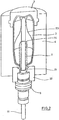
- FIG Fig. 1 The basic structure of a device according to the invention for producing a container (2) from a preform (1) filled with a liquid filling material is shown in FIG Fig. 1 and in Fig. 2 shown.
- the arrangement can be as shown or rotated in a vertical plane by 180 °.
- the device for producing the container (2) consists essentially of a blowing station (3) which is provided with a blow mold (4) into which a preform (1) can be inserted.
- the preform (1) may be an injection-molded part of polyethylene terephthalate.
- the blow mold (4) consists of mold halves (5, 6) and a bottom part (7), which is a lifting device (8) is positionable.
- the preform (1) can be held in the region of the blowing station (3) by a transport mandrel (9) which, together with the preform (1), passes through a plurality of treatment stations within the device. But it is also possible to use the preform (1), for example via pliers or other handling means directly into the blow mold (4).
- a connecting piston (10) is arranged, which feeds the preform (1) compressed air and at the same time makes a seal relative to the transport mandrel (9).
- a connecting piston (10) is arranged, which feeds the preform (1) compressed air and at the same time makes a seal relative to the transport mandrel (9).
- a stretching of the preform (1) takes place in this embodiment by means of a stretching rod (11), which is positioned by a cylinder (12).
- a mechanical positioning of the stretch rod (11) is carried out over curve segments, which are acted upon by Abgriff rollers.
- the use of curve segments is particularly useful when a plurality of blowing stations (3) are arranged on a rotating blowing wheel.
- the stretching system is designed such that a tandem arrangement of two cylinders (12) is provided. From a primary cylinder (13), the stretch rod (11) is first moved to the area of a bottom (14) of the preform (1) before the beginning of the actual stretching operation.
- the primary cylinder (13) is positioned with extended stretch rod together with a primary cylinder (13) carrying slide (15) by a secondary cylinder (16) or via a cam control.
- a current stretching position is predetermined by a guide roller (17) which slides along a curved path during the execution of the stretching operation.
- the guide roller (17) is pressed by the secondary cylinder (16) against the guideway.
- the carriage (15) slides along two guide elements (18).
- the carriers (19, 20) are locked relative to one another by means of a locking device (40).
- Fig. 2 shows in addition to the blown container (2) and dashed lines drawn the preform (1) and schematically a developing container bladder (23).
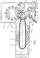
- Fig. 3 shows the basic structure of a blow molding machine, which is provided with a heating section (24) and a rotating blowing wheel (25).
- a preform input (26) the preforms (1) are transported by transfer wheels (27, 28, 29) into the region of the heating path (24).
- Heater (30) and fan (31) are arranged along the heating path (24) in order to temper the preforms (1).
- After a sufficient temperature control of the preforms (1) they are transferred to the blowing wheel (25), in the region of which the blowing stations (3) are arranged.
- the finished blown containers (2) are fed by further transfer wheels to a delivery line (32).
- thermoplastic material different plastics can be used.
- PET polyethylene terephthalate
- PEN polyethylene naphthalate
- PP polypropylene
- the expansion of the preform (1) during the orientation process is carried out by fluid supply.
- the fluid supply is in a Vorblasphase in which gas, for example compressed air, is supplied at a low pressure level and subdivided into a subsequent Hauptblasphase in the liquid product, such as drinking water, is supplied at a higher pressure level.
- gas for example compressed air
- the pre-blowing phase compressed air is typically used at a pressure in the interval of 10 bar to 25 bar, the pre-blowing phase is already ended when the pressure in the developing container bubble has risen to 2 bar to 5 bar.
- the heating section (24) is formed of a plurality of revolving transport elements (33), which are lined up like a chain and guided along deflection wheels (34). In particular, it is thought to open up a substantially rectangular basic contour by the chain-like arrangement.
- a single relatively large-sized guide wheel (34) and in the region of adjacent deflections two comparatively smaller dimensioned guide wheels (36) used , In principle, however, any other guides are conceivable.
- the arrangement shown to be particularly useful since in the region of the corresponding extent of the heating section (24) three deflecting wheels (34, 36) are positioned, and although in each case the smaller deflection wheels (36) in the region of the transition to the linear curves of the heating section (24) and the larger deflection wheel (34) in the immediate transfer area to the transfer wheel (29) and the input wheel (35).
- chain-like transport elements (33) it is also possible, for example, to use a rotating heating wheel.
- modified heating section (24) can be tempered by the larger number of radiant heaters (30) a larger amount of preforms (1) per unit time.
- the fans (31) introduce cooling air into the region of cooling air ducts (39), which in each case oppose the associated radiant heaters (30) and emit the cooling air via outflow openings. By arranging the outflow directions, a flow direction for the cooling air is realized substantially transversely to a transport direction of the preforms (1).
- the cooling air ducts (39) can provide reflectors for the heating radiation in the area opposite the radiant heaters (30), and it is likewise possible to realize cooling of the radiant heaters (30) via the discharged cooling air.
- a transport of the preforms (1) and the container (2) by the blow molding machine can be done in different ways.
- the preforms (1) are carried by transport spikes at least along the essential part of their transport path.
- different variants are conceivable with regard to the spatial orientation of the preforms (1).
- the preform (1) in the region of the preform input (26) is fed with its mouth oriented vertically upwards, then rotated along the heating path (24) and the blowing wheel (25) with its mouth in the vertical direction downwards conveyed oriented and rotated again as a blown and filled container (2) before reaching the output path (32).
- Corresponding transport means for example transport mandrels, have corresponding sealing devices in order to ensure that the product introduced during the blowing process remains in the container (2).
- the preform (1) in the region of the heating section (24) with its mouth in the vertical direction is heated oriented downwards, but rotated again by 180 ° before reaching the blowing wheel (25).
- the preform (1) or the container (2) passes through the entire area of the blow molding machine with its mouth oriented in a vertical direction without performing turning operations.
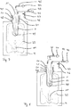
- Fig. 5 shows a blow mold (4), in which a preform (1) is located.
- the preform (1) is arranged, for example, with its mouth section (21) pointing upwards in the blow mold (4).
- a connecting piston (10) which is also referred to as a blowing nozzle, arranged, which seals the preform (1) by means of a seal (48).
- the blowing nozzle (10) defines a gap (41) through which blowing fluids are introduced into the preform (1). Through the gap (41) through a stretch rod (11) is guided, so that the gap (41) in response to the position of the stretch rod (11) assumes a circular or an annular cross-section.
- a compressed air guide is connected or connectable, which comprises a compressed air source (42) and a compressed air valve (43).
- a compressed air source (42)
- a compressed air valve 43
- the preform (1) is longitudinally axial, i.e., longitudinal, by means of the stretching rod (11) which bears against a dome of the preform (1). along a longitudinal axis of the preform (1), stretched.
- a container bladder (23) develops, which, for example, already partly abuts the blow mold (4) at the end of the preblow phase.
- the container bladder (23) is exemplified as a dashed line in FIG Fig. 5 shown.
- Vorblasphase subsequent main blowing liquid contents such as drinking water, from a Gear train (44) under pressure and controlled by a Gearventil (45), introduced into the container bladder (23).
- the pressure of the provided contents is greater than the internal pressure in the container bladder (23), so that the container bladder (23) is further expanded until it rests everywhere on the blow mold (4).
- the pressure within the container bladder (23) continues to increase, wherein the pressure increase can be influenced, for example, by targeted control of an exhaust valve (47) and corresponding discharge of a portion of the blast gas from the container bladder (23) via an exhaust (46).
- the main blowing phase can also be done without discharging blowing gas, for example to achieve the fastest possible increase in pressure within the container bladder (23).
- valves (43, 45, 47) are expressly to be understood as exemplary.
- Alternative solutions are expressly included in the invention.
- the container (2) After forming the container bladder (23), the container (2) is completed and can be removed after pressure relief via the Exhaust (46) as a filled container of the blow mold (4).
- the container (2) is closed before removal, for example, to avoid leakage or spilling out of contents from the container (2) during removal.
- the stretch rod (11) is hollow and has a plurality of outlet openings (49) which open in the lower region of the stretch rod (11) in the preform (1). This makes it possible to introduce the blowing fluids via the stretch rod (11) in the preform (1).
- FIG. 7 Another variant of the invention is in Fig. 7 shown.
- This variant is different from the one in Fig. 6 illustrated variant mainly in that the blowing gas via the blowing nozzle (10) and the contents via the hollow stretching rod (11) is supplied.
- the hollow stretch rod (11) has a single, downwardly directed to the container bottom outlet opening (49).
- This embodiment of the hollow stretch rod (11) is fluidically advantageous for incompressible fluids such as the contents, but it requires that the stretch rod (11) is at least slightly raised after completion of the stretching operation and before the start of the main blowing to allow outflow of the filling material ,
- the embodiments of the hollow stretch rod (11) shown are basically exemplary. In principle, a combination of lateral outflow openings (49) with a central outflow opening (49) on the stretching rod tip is also conceivable. In addition, any embodiments of a hollow stretching rod can be used both for introducing a blowing gas and for introducing a filling material within the scope of the invention.
- a fourth embodiment of the invention is in Fig. 8 represented, in which case the filling material is supplied or introduced both via the blowing nozzle (10) and via the hollow stretching rod (11).
- the cross section or line cross section available for introducing the filling material is increased, so that an increased volume flow for the filling material can be realized.
Landscapes
- Engineering & Computer Science (AREA)
- Mechanical Engineering (AREA)
- Manufacturing & Machinery (AREA)
- Physics & Mathematics (AREA)
- Thermal Sciences (AREA)
- Blow-Moulding Or Thermoforming Of Plastics Or The Like (AREA)
Claims (9)
- Procédé de fabrication d'un récipient (2) rempli d'un produit de remplissage liquide dans le cadre duquel une préforme (1) en un matériau thermoplastique est, après un conditionnement thermique, étirée au moyen d'une barre d'étirage (11) et transformé par un processus de soufflage en récipient (2), le processus de soufflage comportant une phase de pré-soufflage qui met en oeuvre un fluide de soufflage à un premier niveau de pression et une phase de soufflage principal lors de laquelle est utilisé un fluide de soufflage à un second niveau de pression supérieur au premier niveau de pression, le fluide utilisé lors de la phase de pré-soufflage étant un gaz de soufflage et le fluide utilisé pendant la phase de soufflage principal étant le produit de remplissage, caractérisé en ce qu'une partie au moins du gaz de soufflage introduit pendant la phase de pré-soufflage reste dans le récipient (2) jusqu'à la fin de la phase de soufflage principal, le gaz de soufflage contenant une part prédéfinissable de dioxyde de carbone.
- Procédé selon la revendication 1, caractérisé en ce que le gaz de soufflage est introduit par une fente (41) au niveau d'une section d'embouchure (21) de la préforme (1) ou de la bulle (23) qui évolue progressivement pour former le récipient et/ou par une cavité intérieure de la barre d'étirage (11) dans une cavité intérieure de la préforme (1) ou de ladite bulle (23).
- Procédé selon la revendication 1 ou 2, caractérisé en ce que le produit de remplissage est introduit par une fente (41) au niveau d'une section d'embouchure (21) de la préforme (1) ou de la bulle (23) qui évolue progressivement pour former le récipient et/ou par une cavité intérieure de la barre d'étirage (11) dans une cavité intérieure de la préforme (1) ou de ladite bulle (23).
- Procédé selon l'une des revendications 1 à 3, caractérisé en ce que le récipient (2) est obturé à la fin de la phase de soufflage principal, le récipient (2) n'étant notamment retiré du moule de soufflage qu'après son obturation.
- Dispositif de fabrication d'un récipient (2) rempli d'un produit de remplissage liquide comportant un dispositif de chauffage (24) pour le conditionnement thermique de préformes (1) en un matériau thermoplastique et comportant un dispositif de soufflage (3) pour transformer chaque préforme thermiquement conditionnée (1) en un récipient (2), le dispositif de soufflage (3) présentant un moule de soufflage (4) dans lequel vient se loger une préforme (1), une barre d'étirage (11) pour étirer la préforme (1) se trouvant dans le moule de soufflage (4) ainsi que des moyens d'adduction de fluides de soufflage dans une cavité intérieure de la préforme (1) se trouvant dans le moule de soufflage (4), les moyens d'adduction comprenant une première conduite d'amenée conçue pour l'adduction d'un gaz et une seconde conduite d'amenée conçue pour l'adduction d'un liquide, caractérisé en ce que le dispositif présente en outre, pour l'approvisionnement en gaz de soufflage, des moyens d'approvisionnement raccordés de manière à conduire le courant à la première conduite d'amenée, les moyens d'approvisionnement présentant un dispositif mélangeur pour l'approvisionnement avec un mélange de gaz provenant d'au moins deux sources de gaz différentes.
- Dispositif selon la revendication 5, caractérisé en ce que le dispositif de soufflage (3) présente une buse de soufflage (10) pour étanchéifier une préforme (1) logée dans le moule de soufflage (4), notamment pour étanchéifier une cavité intérieure de la préforme (1), cette cavité intérieure de la préforme (1) étant ou pouvant être, au moyen de la buse de soufflage (10), raccordée de manière à conduire le courant à la première conduite d'amenée et/ou à la seconde conduite d'amenée.
- Dispositif selon la revendication 5 ou 6, caractérisé en ce que la barre d'étirage (11) est de conformation creuse, une cavité intérieure de la préforme (1) logée dans le moule de soufflage (4) étant ou pouvant être, au moyen de la barre d'étirage (11), raccordée de manière à conduire le courant à la première conduite d'amenée et/ou à la seconde conduite d'amenée.
- Dispositif selon l'une des revendications 5 à 7, caractérisé en ce que le dispositif comprend en outre une vanne d'inversion sur laquelle sont branchées du côté entrée la première conduite d'amenée et la seconde conduite d'amenée et du côté sortie une troisième conduite d'amenée, la troisième conduite d'amenée étant conçue aussi bien pour l'adduction de gaz que de liquides et une cavité intérieure d'une préforme (1) logée dans le moule de soufflage (4) étant ou pouvant être raccordée de manière à conduire le courant à la troisième conduite d'amenée, notamment au moyen de la buse de soufflage (10) et/ou au moyen de la barre d'étirage creuse (11).
- Dispositif selon l'une des revendications 5 à 8, caractérisé en ce que le dispositif comprend en outre un dispositif d'obturation pour obturer un récipient (2) contenant un produit de remplissage, notamment pour obturer un récipient (2) se trouvant dans le moule de soufflage (4).
Applications Claiming Priority (2)
| Application Number | Priority Date | Filing Date | Title |
|---|---|---|---|
| DE102014004354.1A DE102014004354A1 (de) | 2014-03-27 | 2014-03-27 | Verfahren und Vorrichtung zum Herstellen eines mit Füllgut gefüllten Behälters |
| PCT/EP2015/000574 WO2015144295A1 (fr) | 2014-03-27 | 2015-03-16 | Procédé et dispositif pour la production d'un récipient rempli de matière de remplissage |
Publications (2)
| Publication Number | Publication Date |
|---|---|
| EP3055120A1 EP3055120A1 (fr) | 2016-08-17 |
| EP3055120B1 true EP3055120B1 (fr) | 2019-07-03 |
Family
ID=52814043
Family Applications (1)
| Application Number | Title | Priority Date | Filing Date |
|---|---|---|---|
| EP15712525.3A Active EP3055120B1 (fr) | 2014-03-27 | 2015-03-16 | Procédé et dispositif pour la production d'un récipient rempli de matière de remplissage |
Country Status (5)
| Country | Link |
|---|---|
| US (1) | US11027477B2 (fr) |
| EP (1) | EP3055120B1 (fr) |
| CN (1) | CN106103044B (fr) |
| DE (1) | DE102014004354A1 (fr) |
| WO (1) | WO2015144295A1 (fr) |
Families Citing this family (8)
| Publication number | Priority date | Publication date | Assignee | Title |
|---|---|---|---|---|
| WO2018141347A1 (fr) * | 2017-02-03 | 2018-08-09 | Khs Corpoplast Gmbh | Procédé et dispositif de fabrication de récipients remplis d'un produit de remplissage liquide à partir de préformes, grâce à une matière de remplissage introduite sous pression dans la préforme |
| US11426922B2 (en) | 2017-06-30 | 2022-08-30 | Discma Ag | Method of blow molding |
| DE102017007443A1 (de) * | 2017-08-05 | 2019-02-07 | Kocher-Plastik Maschinenbau Gmbh | Blasform-, Füll- und Schließverfahren sowie danach hergestelltes Behältererzeugnis, insbesondere Ampullenerzeugnis |
| JP6878258B2 (ja) * | 2017-11-27 | 2021-05-26 | 株式会社吉野工業所 | 液体ブロー成形方法 |
| DE102017011087A1 (de) * | 2017-11-30 | 2019-06-06 | Khs Corpoplast Gmbh | Verfahren und Vorrichtung für die Herstellung von gefüllten Behältern aus temperaturkonditionierten Vorformlingen |
| CA3088197C (fr) | 2018-01-11 | 2023-06-20 | Husky Injection Molding Systems Ltd. | Procede et appareil pour donner une forme finale a des contenants en utilisant un liquide devant etre contenu dans lesdits contenants |
| JP7026595B2 (ja) * | 2018-08-31 | 2022-02-28 | 株式会社吉野工業所 | 液体入り容器の製造方法及び製造装置 |
| KR20210111848A (ko) * | 2019-01-31 | 2021-09-13 | 닛세이 에이. 에스. 비 기카이 가부시키가이샤 | 프리폼의 온도조정장치 및 온도조정방법 및 수지성형 용기의 제조장치 및 제조방법 |
Family Cites Families (27)
| Publication number | Priority date | Publication date | Assignee | Title |
|---|---|---|---|---|
| US3969455A (en) * | 1970-05-25 | 1976-07-13 | Continental Can Company, Inc. | Method for forming, sealing, capping and pasteurization of beverage in plastic container |
| US3694424A (en) * | 1970-10-13 | 1972-09-26 | Hunkar Laboratories | Method of internally cooling a blow molded article |
| US3804133A (en) * | 1971-12-07 | 1974-04-16 | Ato Inc | Bottle purging method |
| US3862284A (en) * | 1973-05-10 | 1975-01-21 | Air Prod & Chem | Process for producing blow molded thermoplastic articles having improved barrier properties |
| DE2352926A1 (de) | 1973-10-22 | 1975-04-24 | Heidenreich & Harbeck Gmbh | Verfahren und vorrichtung zum erwaermen eines werkstueckes aus kunststoff |
| US3985156A (en) * | 1974-11-19 | 1976-10-12 | Bristol Screw Products Corporation | Gas and liquid flow control valve |
| GB1474044A (en) * | 1974-12-03 | 1977-05-18 | Ici Ltd | Plastics container manufacture |
| DE3523137C1 (de) * | 1985-06-28 | 1986-04-30 | Audi AG, 8070 Ingolstadt | Verfahren zum Aufblasen und Fluorieren eines Kunststofftanks |
| EP0278119B1 (fr) * | 1986-08-22 | 1991-09-18 | Norgren Martonair Limited | Dispositif pour délivrer un mélange de gaz à un distributeur de boisson |
| US4850850A (en) * | 1987-08-07 | 1989-07-25 | Toyo Seikan Kaisha, Ltd. | Apparatus for preparing heat-set plastic hollow vessel |
| DE4212583A1 (de) | 1992-04-15 | 1993-10-21 | Krupp Corpoplast Masch | Vorrichtung zur Blasformung |
| DE4340291A1 (de) | 1993-11-26 | 1995-06-01 | Krupp Corpoplast Masch | Mehrfachnutzung von Blasluft |
| JPH11227035A (ja) * | 1997-04-11 | 1999-08-24 | Boc Group Inc:The | 単一金型の絞り吹込成形装置の加熱した金型内の物品を冷却する方法 |
| JP4778141B2 (ja) * | 1997-12-19 | 2011-09-21 | トレクセル・インコーポレーテッド | 微孔性フォームの押出し/吹込み成形プロセス及びそれによって製造される製品 |
| DE10028676A1 (de) * | 2000-06-09 | 2002-06-20 | Khs Masch & Anlagenbau Ag | Verfahren zum Füllen von Flaschen, Dosen oder dergleichen Behälter mit einem flüssigen Füllgut sowie Füllmaschine |
| FR2827541B1 (fr) * | 2001-07-20 | 2005-07-01 | Technoplan Engineering S A | Dispositif de soufflage d'emballages |
| FR2848906B1 (fr) | 2002-12-23 | 2006-08-18 | Sidel Sa | Procede et installation de fabrication d'un recipient en matiere plastique |
| US8573964B2 (en) | 2006-04-13 | 2013-11-05 | Amcor Limited | Liquid or hydraulic blow molding |
| DE102006032140A1 (de) * | 2006-07-12 | 2008-02-21 | Sig Technology Ltd. | Verfahren und Vorrichtung zur Blasformung von Behältern |
| FR2909303B1 (fr) * | 2006-12-05 | 2009-03-27 | Sidel Participations | Procede de fabrication d'un recipient a partir d'une ebauche,avec retroaction en fonction du point de fin d'expansion de l'ebauche |
| WO2008098938A1 (fr) * | 2007-02-12 | 2008-08-21 | Inbev S.A. | Procédé de fabrication d'un contenant |
| EP2143544A1 (fr) * | 2008-07-07 | 2010-01-13 | Nestec S.A. | Procédé et dispositif de conditionnement d'un liquide alimentaire |
| MX2011012864A (es) * | 2009-06-05 | 2012-02-23 | Sidel Spa Con Socio Unico | Maquina de llenado y metodo de llenado de un envase. |
| FR2953735B1 (fr) * | 2009-12-16 | 2013-03-29 | Inst Francais Du Petrole | Procede d'elimination de composes acides d'un effluent gazeux avec une solution absorbante a base de diamines i,ii/iii. |
| FR2962930B1 (fr) * | 2010-07-20 | 2012-08-31 | Sidel Participations | Procede de formage d'un recipient par soufflage et remplissage |
| FR2962931B1 (fr) * | 2010-07-20 | 2014-02-14 | Sidel Participations | Dispositif d'injection d'au moins deux fluides sous pression dans le col d'un recipient pour le formage dudit recipient |
| EP2670666B1 (fr) * | 2011-01-31 | 2020-03-04 | KHS GmbH | Procédé et appareil pour fabriquer de récipients remplis d'un liquide |
-
2014
- 2014-03-27 DE DE102014004354.1A patent/DE102014004354A1/de not_active Withdrawn
-
2015
- 2015-03-16 US US15/104,235 patent/US11027477B2/en active Active
- 2015-03-16 WO PCT/EP2015/000574 patent/WO2015144295A1/fr active Application Filing
- 2015-03-16 CN CN201580015054.8A patent/CN106103044B/zh active Active
- 2015-03-16 EP EP15712525.3A patent/EP3055120B1/fr active Active
Non-Patent Citations (1)
| Title |
|---|
| None * |
Also Published As
| Publication number | Publication date |
|---|---|
| US20160318230A1 (en) | 2016-11-03 |
| US11027477B2 (en) | 2021-06-08 |
| WO2015144295A1 (fr) | 2015-10-01 |
| CN106103044B (zh) | 2019-04-23 |
| DE102014004354A1 (de) | 2015-10-01 |
| CN106103044A (zh) | 2016-11-09 |
| EP3055120A1 (fr) | 2016-08-17 |
Similar Documents
| Publication | Publication Date | Title |
|---|---|---|
| EP3055120B1 (fr) | Procédé et dispositif pour la production d'un récipient rempli de matière de remplissage | |
| EP2144742B1 (fr) | Dispositif de moulage par soufflage de récipients | |
| EP2040905B1 (fr) | Procédé et dispositif de moulage de récipients par soufflage | |
| DE112006000800B4 (de) | Verfahren und Vorrichtung zur Blasformung von Behältern unter Verwendung eines beweglich geführten Ventilträgers | |
| WO2011091780A2 (fr) | Procédé et dispositif de moulage par soufflage de récipients | |
| EP2176053B2 (fr) | Dispositif de soufflage de récipients | |
| DE102011012664A1 (de) | Verfahren und Vorrichtung zur Herstellung von mit einem flüssigen Füllgut gefüllten Behältern | |
| DE102005008685A1 (de) | Verfahren und Vorrichtung zur Blasformung von Behältern | |
| DE102010001096A1 (de) | Vorrichtung und Verfahren zum Herstellen von Behältern aus Kunststoff | |
| EP1660303B1 (fr) | Procede et dispositif de moulage par soufflage de recipients | |
| EP2694270B1 (fr) | Dispositif pour le moulage de recipients par soufflage | |
| EP2533965B1 (fr) | Procédé et dispositif de moulage de récipients par soufflage | |
| EP1660301B2 (fr) | Procede et dispositif de moulage par soufflage de recipients | |
| EP2544875B1 (fr) | Procédé et dispositif pour le moulage par soufflage de contenants | |
| DE19925756A1 (de) | Verfahren und Vorrichtung zur Blasformung von Behältern | |
| EP1660302B1 (fr) | Procede et dispositif de moulage par soufflage de pieces a l'aide d'une broche d'etirage par soufflage pourvue d'orifices d'amenee d'air speciaux | |
| DE102004018146A1 (de) | Verfahren und Vorrichtung zur Blasformung von Behältern | |
| DE102004012124A1 (de) | Verfahren und Vorrichtung zur Blasformung von Behältern | |
| EP2681031B1 (fr) | Preocede et dispositif de manipulation de paraisons | |
| DE102005000681A1 (de) | Vefahren und Vorrichtung zur Blasformung von Behältern | |
| DE102004003939A1 (de) | Verfahren und Vorrichtung zur Blasformung von Behältern | |
| EP2129508B1 (fr) | Procédé de moulage par soufflage de contenants | |
| DE10318556A1 (de) | Verfahren und Vorrichtung zur Blasformung von Behältern | |
| DE3819129A1 (de) | Verfahren zur herstellung von kunststoff-flaschen sowie extrusions-blasformmaschine zur durchfuehrung des verfahrens |
Legal Events
| Date | Code | Title | Description |
|---|---|---|---|
| PUAI | Public reference made under article 153(3) epc to a published international application that has entered the european phase |
Free format text: ORIGINAL CODE: 0009012 |
|
| 17P | Request for examination filed |
Effective date: 20160407 |
|
| AK | Designated contracting states |
Kind code of ref document: A1 Designated state(s): AL AT BE BG CH CY CZ DE DK EE ES FI FR GB GR HR HU IE IS IT LI LT LU LV MC MK MT NL NO PL PT RO RS SE SI SK SM TR |
|
| AX | Request for extension of the european patent |
Extension state: BA ME |
|
| RIN1 | Information on inventor provided before grant (corrected) |
Inventor name: LITZENBERG, MICHAEL Inventor name: BAUMGARTE, ROLF Inventor name: LINKE, MICHAEL |
|
| DAV | Request for validation of the european patent (deleted) | ||
| DAX | Request for extension of the european patent (deleted) | ||
| GRAP | Despatch of communication of intention to grant a patent |
Free format text: ORIGINAL CODE: EPIDOSNIGR1 |
|
| STAA | Information on the status of an ep patent application or granted ep patent |
Free format text: STATUS: GRANT OF PATENT IS INTENDED |
|
| RIC1 | Information provided on ipc code assigned before grant |
Ipc: B29C 49/18 20060101ALN20190131BHEP Ipc: B29K 67/00 20060101ALN20190131BHEP Ipc: B29C 49/06 20060101ALN20190131BHEP Ipc: B29C 49/46 20060101AFI20190131BHEP Ipc: B65B 3/02 20060101ALN20190131BHEP Ipc: B29C 49/64 20060101ALN20190131BHEP Ipc: B29L 31/00 20060101ALN20190131BHEP Ipc: B29C 49/12 20060101ALI20190131BHEP Ipc: B29C 49/36 20060101ALN20190131BHEP |
|
| INTG | Intention to grant announced |
Effective date: 20190214 |
|
| GRAS | Grant fee paid |
Free format text: ORIGINAL CODE: EPIDOSNIGR3 |
|
| GRAA | (expected) grant |
Free format text: ORIGINAL CODE: 0009210 |
|
| STAA | Information on the status of an ep patent application or granted ep patent |
Free format text: STATUS: THE PATENT HAS BEEN GRANTED |
|
| AK | Designated contracting states |
Kind code of ref document: B1 Designated state(s): AL AT BE BG CH CY CZ DE DK EE ES FI FR GB GR HR HU IE IS IT LI LT LU LV MC MK MT NL NO PL PT RO RS SE SI SK SM TR |
|
| REG | Reference to a national code |
Ref country code: GB Ref legal event code: FG4D Free format text: NOT ENGLISH |
|
| REG | Reference to a national code |
Ref country code: CH Ref legal event code: EP Ref country code: AT Ref legal event code: REF Ref document number: 1150440 Country of ref document: AT Kind code of ref document: T Effective date: 20190715 |
|
| REG | Reference to a national code |
Ref country code: IE Ref legal event code: FG4D Free format text: LANGUAGE OF EP DOCUMENT: GERMAN |
|
| REG | Reference to a national code |
Ref country code: DE Ref legal event code: R096 Ref document number: 502015009514 Country of ref document: DE |
|
| REG | Reference to a national code |
Ref country code: CH Ref legal event code: NV Representative=s name: R.A. EGLI AND CO, PATENTANWAELTE, CH |
|
| REG | Reference to a national code |
Ref country code: NL Ref legal event code: MP Effective date: 20190703 |
|
| REG | Reference to a national code |
Ref country code: LT Ref legal event code: MG4D |
|
| PG25 | Lapsed in a contracting state [announced via postgrant information from national office to epo] |
Ref country code: SE Free format text: LAPSE BECAUSE OF FAILURE TO SUBMIT A TRANSLATION OF THE DESCRIPTION OR TO PAY THE FEE WITHIN THE PRESCRIBED TIME-LIMIT Effective date: 20190703 Ref country code: NO Free format text: LAPSE BECAUSE OF FAILURE TO SUBMIT A TRANSLATION OF THE DESCRIPTION OR TO PAY THE FEE WITHIN THE PRESCRIBED TIME-LIMIT Effective date: 20191003 Ref country code: FI Free format text: LAPSE BECAUSE OF FAILURE TO SUBMIT A TRANSLATION OF THE DESCRIPTION OR TO PAY THE FEE WITHIN THE PRESCRIBED TIME-LIMIT Effective date: 20190703 Ref country code: PT Free format text: LAPSE BECAUSE OF FAILURE TO SUBMIT A TRANSLATION OF THE DESCRIPTION OR TO PAY THE FEE WITHIN THE PRESCRIBED TIME-LIMIT Effective date: 20191104 Ref country code: HR Free format text: LAPSE BECAUSE OF FAILURE TO SUBMIT A TRANSLATION OF THE DESCRIPTION OR TO PAY THE FEE WITHIN THE PRESCRIBED TIME-LIMIT Effective date: 20190703 Ref country code: BG Free format text: LAPSE BECAUSE OF FAILURE TO SUBMIT A TRANSLATION OF THE DESCRIPTION OR TO PAY THE FEE WITHIN THE PRESCRIBED TIME-LIMIT Effective date: 20191003 Ref country code: NL Free format text: LAPSE BECAUSE OF FAILURE TO SUBMIT A TRANSLATION OF THE DESCRIPTION OR TO PAY THE FEE WITHIN THE PRESCRIBED TIME-LIMIT Effective date: 20190703 Ref country code: CZ Free format text: LAPSE BECAUSE OF FAILURE TO SUBMIT A TRANSLATION OF THE DESCRIPTION OR TO PAY THE FEE WITHIN THE PRESCRIBED TIME-LIMIT Effective date: 20190703 Ref country code: LT Free format text: LAPSE BECAUSE OF FAILURE TO SUBMIT A TRANSLATION OF THE DESCRIPTION OR TO PAY THE FEE WITHIN THE PRESCRIBED TIME-LIMIT Effective date: 20190703 |
|
| PG25 | Lapsed in a contracting state [announced via postgrant information from national office to epo] |
Ref country code: GR Free format text: LAPSE BECAUSE OF FAILURE TO SUBMIT A TRANSLATION OF THE DESCRIPTION OR TO PAY THE FEE WITHIN THE PRESCRIBED TIME-LIMIT Effective date: 20191004 Ref country code: AL Free format text: LAPSE BECAUSE OF FAILURE TO SUBMIT A TRANSLATION OF THE DESCRIPTION OR TO PAY THE FEE WITHIN THE PRESCRIBED TIME-LIMIT Effective date: 20190703 Ref country code: LV Free format text: LAPSE BECAUSE OF FAILURE TO SUBMIT A TRANSLATION OF THE DESCRIPTION OR TO PAY THE FEE WITHIN THE PRESCRIBED TIME-LIMIT Effective date: 20190703 Ref country code: IS Free format text: LAPSE BECAUSE OF FAILURE TO SUBMIT A TRANSLATION OF THE DESCRIPTION OR TO PAY THE FEE WITHIN THE PRESCRIBED TIME-LIMIT Effective date: 20191103 Ref country code: RS Free format text: LAPSE BECAUSE OF FAILURE TO SUBMIT A TRANSLATION OF THE DESCRIPTION OR TO PAY THE FEE WITHIN THE PRESCRIBED TIME-LIMIT Effective date: 20190703 Ref country code: ES Free format text: LAPSE BECAUSE OF FAILURE TO SUBMIT A TRANSLATION OF THE DESCRIPTION OR TO PAY THE FEE WITHIN THE PRESCRIBED TIME-LIMIT Effective date: 20190703 |
|
| PG25 | Lapsed in a contracting state [announced via postgrant information from national office to epo] |
Ref country code: TR Free format text: LAPSE BECAUSE OF FAILURE TO SUBMIT A TRANSLATION OF THE DESCRIPTION OR TO PAY THE FEE WITHIN THE PRESCRIBED TIME-LIMIT Effective date: 20190703 |
|
| PG25 | Lapsed in a contracting state [announced via postgrant information from national office to epo] |
Ref country code: RO Free format text: LAPSE BECAUSE OF FAILURE TO SUBMIT A TRANSLATION OF THE DESCRIPTION OR TO PAY THE FEE WITHIN THE PRESCRIBED TIME-LIMIT Effective date: 20190703 Ref country code: PL Free format text: LAPSE BECAUSE OF FAILURE TO SUBMIT A TRANSLATION OF THE DESCRIPTION OR TO PAY THE FEE WITHIN THE PRESCRIBED TIME-LIMIT Effective date: 20190703 Ref country code: DK Free format text: LAPSE BECAUSE OF FAILURE TO SUBMIT A TRANSLATION OF THE DESCRIPTION OR TO PAY THE FEE WITHIN THE PRESCRIBED TIME-LIMIT Effective date: 20190703 Ref country code: EE Free format text: LAPSE BECAUSE OF FAILURE TO SUBMIT A TRANSLATION OF THE DESCRIPTION OR TO PAY THE FEE WITHIN THE PRESCRIBED TIME-LIMIT Effective date: 20190703 |
|
| PG25 | Lapsed in a contracting state [announced via postgrant information from national office to epo] |
Ref country code: IS Free format text: LAPSE BECAUSE OF FAILURE TO SUBMIT A TRANSLATION OF THE DESCRIPTION OR TO PAY THE FEE WITHIN THE PRESCRIBED TIME-LIMIT Effective date: 20200224 Ref country code: SM Free format text: LAPSE BECAUSE OF FAILURE TO SUBMIT A TRANSLATION OF THE DESCRIPTION OR TO PAY THE FEE WITHIN THE PRESCRIBED TIME-LIMIT Effective date: 20190703 Ref country code: SK Free format text: LAPSE BECAUSE OF FAILURE TO SUBMIT A TRANSLATION OF THE DESCRIPTION OR TO PAY THE FEE WITHIN THE PRESCRIBED TIME-LIMIT Effective date: 20190703 |
|
| REG | Reference to a national code |
Ref country code: DE Ref legal event code: R097 Ref document number: 502015009514 Country of ref document: DE |
|
| PLBE | No opposition filed within time limit |
Free format text: ORIGINAL CODE: 0009261 |
|
| STAA | Information on the status of an ep patent application or granted ep patent |
Free format text: STATUS: NO OPPOSITION FILED WITHIN TIME LIMIT |
|
| PG2D | Information on lapse in contracting state deleted |
Ref country code: IS |
|
| 26N | No opposition filed |
Effective date: 20200603 |
|
| PG25 | Lapsed in a contracting state [announced via postgrant information from national office to epo] |
Ref country code: SI Free format text: LAPSE BECAUSE OF FAILURE TO SUBMIT A TRANSLATION OF THE DESCRIPTION OR TO PAY THE FEE WITHIN THE PRESCRIBED TIME-LIMIT Effective date: 20190703 |
|
| PG25 | Lapsed in a contracting state [announced via postgrant information from national office to epo] |
Ref country code: MC Free format text: LAPSE BECAUSE OF FAILURE TO SUBMIT A TRANSLATION OF THE DESCRIPTION OR TO PAY THE FEE WITHIN THE PRESCRIBED TIME-LIMIT Effective date: 20190703 |
|
| REG | Reference to a national code |
Ref country code: BE Ref legal event code: MM Effective date: 20200331 |
|
| PG25 | Lapsed in a contracting state [announced via postgrant information from national office to epo] |
Ref country code: LU Free format text: LAPSE BECAUSE OF NON-PAYMENT OF DUE FEES Effective date: 20200316 |
|
| PG25 | Lapsed in a contracting state [announced via postgrant information from national office to epo] |
Ref country code: IE Free format text: LAPSE BECAUSE OF NON-PAYMENT OF DUE FEES Effective date: 20200316 |
|
| REG | Reference to a national code |
Ref country code: DE Ref legal event code: R082 Ref document number: 502015009514 Country of ref document: DE Representative=s name: EISENFUEHR SPEISER PATENTANWAELTE RECHTSANWAEL, DE |
|
| PG25 | Lapsed in a contracting state [announced via postgrant information from national office to epo] |
Ref country code: BE Free format text: LAPSE BECAUSE OF NON-PAYMENT OF DUE FEES Effective date: 20200331 |
|
| GBPC | Gb: european patent ceased through non-payment of renewal fee |
Effective date: 20200316 |
|
| PG25 | Lapsed in a contracting state [announced via postgrant information from national office to epo] |
Ref country code: GB Free format text: LAPSE BECAUSE OF NON-PAYMENT OF DUE FEES Effective date: 20200316 |
|
| REG | Reference to a national code |
Ref country code: AT Ref legal event code: MM01 Ref document number: 1150440 Country of ref document: AT Kind code of ref document: T Effective date: 20200316 |
|
| PG25 | Lapsed in a contracting state [announced via postgrant information from national office to epo] |
Ref country code: AT Free format text: LAPSE BECAUSE OF NON-PAYMENT OF DUE FEES Effective date: 20200316 |
|
| PG25 | Lapsed in a contracting state [announced via postgrant information from national office to epo] |
Ref country code: MT Free format text: LAPSE BECAUSE OF FAILURE TO SUBMIT A TRANSLATION OF THE DESCRIPTION OR TO PAY THE FEE WITHIN THE PRESCRIBED TIME-LIMIT Effective date: 20190703 Ref country code: CY Free format text: LAPSE BECAUSE OF FAILURE TO SUBMIT A TRANSLATION OF THE DESCRIPTION OR TO PAY THE FEE WITHIN THE PRESCRIBED TIME-LIMIT Effective date: 20190703 |
|
| PG25 | Lapsed in a contracting state [announced via postgrant information from national office to epo] |
Ref country code: MK Free format text: LAPSE BECAUSE OF FAILURE TO SUBMIT A TRANSLATION OF THE DESCRIPTION OR TO PAY THE FEE WITHIN THE PRESCRIBED TIME-LIMIT Effective date: 20190703 |
|
| REG | Reference to a national code |
Ref country code: DE Ref legal event code: R082 Ref document number: 502015009514 Country of ref document: DE Ref country code: DE Ref legal event code: R081 Ref document number: 502015009514 Country of ref document: DE Owner name: KHS GMBH, DE Free format text: FORMER OWNER: KHS CORPOPLAST GMBH, 22145 HAMBURG, DE Ref country code: DE Ref legal event code: R082 Ref document number: 502015009514 Country of ref document: DE Representative=s name: EISENFUEHR SPEISER PATENTANWAELTE RECHTSANWAEL, DE |
|
| REG | Reference to a national code |
Ref country code: DE Ref legal event code: R082 Ref document number: 502015009514 Country of ref document: DE Representative=s name: EISENFUEHR SPEISER PATENTANWAELTE RECHTSANWAEL, DE |
|
| PGFP | Annual fee paid to national office [announced via postgrant information from national office to epo] |
Ref country code: FR Payment date: 20230324 Year of fee payment: 9 |
|
| PGFP | Annual fee paid to national office [announced via postgrant information from national office to epo] |
Ref country code: IT Payment date: 20230328 Year of fee payment: 9 Ref country code: CH Payment date: 20230401 Year of fee payment: 9 |
|
| PGFP | Annual fee paid to national office [announced via postgrant information from national office to epo] |
Ref country code: DE Payment date: 20240320 Year of fee payment: 10 |