EP3054873B1 - Implantierbare vertebrale arthrodesevorrichtung zur fusion zweier darüber und darunter liegender wirbel - Google Patents
Implantierbare vertebrale arthrodesevorrichtung zur fusion zweier darüber und darunter liegender wirbel Download PDFInfo
- Publication number
- EP3054873B1 EP3054873B1 EP14790230.8A EP14790230A EP3054873B1 EP 3054873 B1 EP3054873 B1 EP 3054873B1 EP 14790230 A EP14790230 A EP 14790230A EP 3054873 B1 EP3054873 B1 EP 3054873B1
- Authority
- EP
- European Patent Office
- Prior art keywords
- implantable device
- anterior portion
- posterior
- anterior
- partitioning element
- Prior art date
- Legal status (The legal status is an assumption and is not a legal conclusion. Google has not performed a legal analysis and makes no representation as to the accuracy of the status listed.)
- Not-in-force
Links
- 208000037873 arthrodesis Diseases 0.000 title claims description 10
- 239000000463 material Substances 0.000 claims description 41
- 238000000034 method Methods 0.000 claims description 35
- 238000000638 solvent extraction Methods 0.000 claims description 32
- 230000005012 migration Effects 0.000 claims description 4
- 238000013508 migration Methods 0.000 claims description 4
- 210000000988 bone and bone Anatomy 0.000 description 24
- 230000004927 fusion Effects 0.000 description 22
- 238000005192 partition Methods 0.000 description 12
- 208000007623 Lordosis Diseases 0.000 description 8
- -1 polyethylene terephthalate Polymers 0.000 description 6
- 229910052588 hydroxylapatite Inorganic materials 0.000 description 5
- XYJRXVWERLGGKC-UHFFFAOYSA-D pentacalcium;hydroxide;triphosphate Chemical compound [OH-].[Ca+2].[Ca+2].[Ca+2].[Ca+2].[Ca+2].[O-]P([O-])([O-])=O.[O-]P([O-])([O-])=O.[O-]P([O-])([O-])=O XYJRXVWERLGGKC-UHFFFAOYSA-D 0.000 description 5
- 239000004753 textile Substances 0.000 description 5
- 239000004696 Poly ether ether ketone Substances 0.000 description 4
- 238000002513 implantation Methods 0.000 description 4
- 229920002530 polyetherether ketone Polymers 0.000 description 4
- 229920000139 polyethylene terephthalate Polymers 0.000 description 4
- 239000005020 polyethylene terephthalate Substances 0.000 description 4
- 241001465754 Metazoa Species 0.000 description 3
- 239000011248 coating agent Substances 0.000 description 3
- 238000000576 coating method Methods 0.000 description 3
- 229920001343 polytetrafluoroethylene Polymers 0.000 description 3
- 239000004810 polytetrafluoroethylene Substances 0.000 description 3
- 238000001356 surgical procedure Methods 0.000 description 3
- 210000001519 tissue Anatomy 0.000 description 3
- AEMRFAOFKBGASW-UHFFFAOYSA-N Glycolic acid Chemical compound OCC(O)=O AEMRFAOFKBGASW-UHFFFAOYSA-N 0.000 description 2
- 206010061246 Intervertebral disc degeneration Diseases 0.000 description 2
- 239000004743 Polypropylene Substances 0.000 description 2
- 239000002639 bone cement Substances 0.000 description 2
- 230000006835 compression Effects 0.000 description 2
- 238000007906 compression Methods 0.000 description 2
- 239000007943 implant Substances 0.000 description 2
- JVTAAEKCZFNVCJ-UHFFFAOYSA-N lactic acid Chemical compound CC(O)C(O)=O JVTAAEKCZFNVCJ-UHFFFAOYSA-N 0.000 description 2
- 210000003041 ligament Anatomy 0.000 description 2
- 238000012423 maintenance Methods 0.000 description 2
- 230000017074 necrotic cell death Effects 0.000 description 2
- 229920001155 polypropylene Polymers 0.000 description 2
- RBMHUYBJIYNRLY-UHFFFAOYSA-N 2-[(1-carboxy-1-hydroxyethyl)-hydroxyphosphoryl]-2-hydroxypropanoic acid Chemical compound OC(=O)C(O)(C)P(O)(=O)C(C)(O)C(O)=O RBMHUYBJIYNRLY-UHFFFAOYSA-N 0.000 description 1
- 208000008035 Back Pain Diseases 0.000 description 1
- OKTJSMMVPCPJKN-UHFFFAOYSA-N Carbon Chemical compound [C] OKTJSMMVPCPJKN-UHFFFAOYSA-N 0.000 description 1
- 241001269524 Dura Species 0.000 description 1
- 208000003618 Intervertebral Disc Displacement Diseases 0.000 description 1
- 206010050296 Intervertebral disc protrusion Diseases 0.000 description 1
- JVTAAEKCZFNVCJ-REOHCLBHSA-N L-lactic acid Chemical compound C[C@H](O)C(O)=O JVTAAEKCZFNVCJ-REOHCLBHSA-N 0.000 description 1
- 208000008930 Low Back Pain Diseases 0.000 description 1
- 229910019142 PO4 Inorganic materials 0.000 description 1
- 229920008285 Poly(ether ketone) PEK Polymers 0.000 description 1
- 239000004952 Polyamide Substances 0.000 description 1
- RTAQQCXQSZGOHL-UHFFFAOYSA-N Titanium Chemical compound [Ti] RTAQQCXQSZGOHL-UHFFFAOYSA-N 0.000 description 1
- ZYPGADGCNXOUJP-CXVPHVKISA-N Variotin Chemical compound CCCC[C@@H](O)\C=C(/C)\C=C\C=C\C(=O)N1CCCC1=O ZYPGADGCNXOUJP-CXVPHVKISA-N 0.000 description 1
- 208000027418 Wounds and injury Diseases 0.000 description 1
- 230000004913 activation Effects 0.000 description 1
- 238000004026 adhesive bonding Methods 0.000 description 1
- 230000015572 biosynthetic process Effects 0.000 description 1
- 229910052799 carbon Inorganic materials 0.000 description 1
- 150000004649 carbonic acid derivatives Chemical class 0.000 description 1
- 239000000919 ceramic Substances 0.000 description 1
- 229920001577 copolymer Polymers 0.000 description 1
- 230000001054 cortical effect Effects 0.000 description 1
- 230000006378 damage Effects 0.000 description 1
- 230000007850 degeneration Effects 0.000 description 1
- 208000018180 degenerative disc disease Diseases 0.000 description 1
- 230000003412 degenerative effect Effects 0.000 description 1
- 239000010432 diamond Substances 0.000 description 1
- 201000010099 disease Diseases 0.000 description 1
- 208000037265 diseases, disorders, signs and symptoms Diseases 0.000 description 1
- 239000004744 fabric Substances 0.000 description 1
- 208000014674 injury Diseases 0.000 description 1
- 208000021600 intervertebral disc degenerative disease Diseases 0.000 description 1
- 235000014655 lactic acid Nutrition 0.000 description 1
- 239000004310 lactic acid Substances 0.000 description 1
- 239000000203 mixture Substances 0.000 description 1
- 230000001338 necrotic effect Effects 0.000 description 1
- 210000005036 nerve Anatomy 0.000 description 1
- 230000007170 pathology Effects 0.000 description 1
- 235000021317 phosphate Nutrition 0.000 description 1
- 150000003013 phosphoric acid derivatives Chemical class 0.000 description 1
- 229920001434 poly(D-lactide) Polymers 0.000 description 1
- 229920001432 poly(L-lactide) Polymers 0.000 description 1
- 229920000747 poly(lactic acid) Polymers 0.000 description 1
- 229920003229 poly(methyl methacrylate) Polymers 0.000 description 1
- 229920002647 polyamide Polymers 0.000 description 1
- 239000004626 polylactic acid Substances 0.000 description 1
- 239000004926 polymethyl methacrylate Substances 0.000 description 1
- 229920001296 polysiloxane Polymers 0.000 description 1
- 238000007665 sagging Methods 0.000 description 1
- 229920006268 silicone film Polymers 0.000 description 1
- 239000007787 solid Substances 0.000 description 1
- 210000000273 spinal nerve root Anatomy 0.000 description 1
- 150000003467 sulfuric acid derivatives Chemical class 0.000 description 1
- 229920002994 synthetic fiber Polymers 0.000 description 1
- 210000000115 thoracic cavity Anatomy 0.000 description 1
- 229910052719 titanium Inorganic materials 0.000 description 1
- 239000010936 titanium Substances 0.000 description 1
Images
Classifications
-
- A—HUMAN NECESSITIES
- A61—MEDICAL OR VETERINARY SCIENCE; HYGIENE
- A61B—DIAGNOSIS; SURGERY; IDENTIFICATION
- A61B17/00—Surgical instruments, devices or methods
- A61B17/56—Surgical instruments or methods for treatment of bones or joints; Devices specially adapted therefor
- A61B17/58—Surgical instruments or methods for treatment of bones or joints; Devices specially adapted therefor for osteosynthesis, e.g. bone plates, screws or setting implements
- A61B17/68—Internal fixation devices, including fasteners and spinal fixators, even if a part thereof projects from the skin
- A61B17/70—Spinal positioners or stabilisers, e.g. stabilisers comprising fluid filler in an implant
- A61B17/7062—Devices acting on, attached to, or simulating the effect of, vertebral processes, vertebral facets or ribs ; Tools for such devices
-
- A—HUMAN NECESSITIES
- A61—MEDICAL OR VETERINARY SCIENCE; HYGIENE
- A61F—FILTERS IMPLANTABLE INTO BLOOD VESSELS; PROSTHESES; DEVICES PROVIDING PATENCY TO, OR PREVENTING COLLAPSING OF, TUBULAR STRUCTURES OF THE BODY, e.g. STENTS; ORTHOPAEDIC, NURSING OR CONTRACEPTIVE DEVICES; FOMENTATION; TREATMENT OR PROTECTION OF EYES OR EARS; BANDAGES, DRESSINGS OR ABSORBENT PADS; FIRST-AID KITS
- A61F2/00—Filters implantable into blood vessels; Prostheses, i.e. artificial substitutes or replacements for parts of the body; Appliances for connecting them with the body; Devices providing patency to, or preventing collapsing of, tubular structures of the body, e.g. stents
- A61F2/02—Prostheses implantable into the body
- A61F2/30—Joints
- A61F2/44—Joints for the spine, e.g. vertebrae, spinal discs
- A61F2/4405—Joints for the spine, e.g. vertebrae, spinal discs for apophyseal or facet joints, i.e. between adjacent spinous or transverse processes
-
- A—HUMAN NECESSITIES
- A61—MEDICAL OR VETERINARY SCIENCE; HYGIENE
- A61F—FILTERS IMPLANTABLE INTO BLOOD VESSELS; PROSTHESES; DEVICES PROVIDING PATENCY TO, OR PREVENTING COLLAPSING OF, TUBULAR STRUCTURES OF THE BODY, e.g. STENTS; ORTHOPAEDIC, NURSING OR CONTRACEPTIVE DEVICES; FOMENTATION; TREATMENT OR PROTECTION OF EYES OR EARS; BANDAGES, DRESSINGS OR ABSORBENT PADS; FIRST-AID KITS
- A61F2/00—Filters implantable into blood vessels; Prostheses, i.e. artificial substitutes or replacements for parts of the body; Appliances for connecting them with the body; Devices providing patency to, or preventing collapsing of, tubular structures of the body, e.g. stents
- A61F2/02—Prostheses implantable into the body
- A61F2/30—Joints
- A61F2002/30001—Additional features of subject-matter classified in A61F2/28, A61F2/30 and subgroups thereof
- A61F2002/30316—The prosthesis having different structural features at different locations within the same prosthesis; Connections between prosthetic parts; Special structural features of bone or joint prostheses not otherwise provided for
- A61F2002/30535—Special structural features of bone or joint prostheses not otherwise provided for
- A61F2002/30593—Special structural features of bone or joint prostheses not otherwise provided for hollow
-
- A—HUMAN NECESSITIES
- A61—MEDICAL OR VETERINARY SCIENCE; HYGIENE
- A61F—FILTERS IMPLANTABLE INTO BLOOD VESSELS; PROSTHESES; DEVICES PROVIDING PATENCY TO, OR PREVENTING COLLAPSING OF, TUBULAR STRUCTURES OF THE BODY, e.g. STENTS; ORTHOPAEDIC, NURSING OR CONTRACEPTIVE DEVICES; FOMENTATION; TREATMENT OR PROTECTION OF EYES OR EARS; BANDAGES, DRESSINGS OR ABSORBENT PADS; FIRST-AID KITS
- A61F2/00—Filters implantable into blood vessels; Prostheses, i.e. artificial substitutes or replacements for parts of the body; Appliances for connecting them with the body; Devices providing patency to, or preventing collapsing of, tubular structures of the body, e.g. stents
- A61F2/02—Prostheses implantable into the body
- A61F2/30—Joints
- A61F2002/30001—Additional features of subject-matter classified in A61F2/28, A61F2/30 and subgroups thereof
- A61F2002/30621—Features concerning the anatomical functioning or articulation of the prosthetic joint
- A61F2002/30622—Implant for fusing a joint or bone material
Definitions
- the present invention relates to the technical field of implantable vertebral arthrodesis devices for the fusion of two supra and underlying vertebrae.
- Arthrodesis is understood to mean any fusion of a joint.
- These implantable devices have the function of distributing the charges and overloads between two adjacent vertebrae (hereinafter referred to as vertebrae and underlying) created by the disc degeneration (in particular in the case of a herniated disc).
- vertebrae and underlying two adjacent vertebrae
- the disc degeneration in particular in the case of a herniated disc.
- a constraint or injury to a disc may result in tearing or protuberance, possibly resulting in contact and compression of a spinal nerve root. Contact on the nerve may cause intermittent low back pain.
- One method of treating this type of pathology is to immobilize the supral and underlying vertebrae by bone fusion while restoring the interspinous distance of said vertebrae and their lordosis angle.
- the implantable devices most commonly used in this method of surgical treatment include two rods connected to the above and underlying vertebrae by screws positioned in the pedicles, vertebrae to which an osteosynthesis graft positioned on the external parts of the screws and rods.
- This type of implantable device imposes an opening of the operative field causing necrosis of the surrounding tissues manipulated on the patient to access the pedicles and put in place the screws and the graft.
- these devices also comprise one or two inter-somatic cage (s), inserted (s) by the posterior, lateral or anterior way, which increases the time of the surgery and therefore the risks for the patient.
- WO 2013/123497 relates to an interspinous fusion device comprising a central body portion which is defined between first and second opposite and lower walls, a rear wall and first and second upper edges.
- the central body portion open on its posterior part, can receive only one graft in the form of a solid block.
- US 2012/0215262 relates to an osteosynthesis device intended to be placed between the spinous processes. This device does not allow an inter-lamar fusion.
- US 8,292,923 B1 relates to an implant intended to be placed between the spinous processes.
- This implant also does not provide inter-lam support and does not allow inter-lamar fusion.
- it is not arranged to receive at least in part the spinous processes. Indeed, the central cavity is only a few millimeters and just comes in superficial contact with the spinous.
- a vertebral arthrodesis device for the fusion of two adjacent vertebrae, in particular at the lumbar level, in particular in the treatment of degenerative or accidental disc disease, which does not require the use of screws and stems in order to reduce the operative field on the patient, and to reduce the necrosis of the surrounding tissues on the implantation site.
- Vertebral arthrodesis is understood to mean any arthrodesis performed on the cervical vertebrae or the dorsal or thoracic vertebrae or the lumbar vertebrae or the vertebrae of the sacrum, preferably on the lumbar vertebrae.
- the posterior part in connection with the anterior part, that the posterior part is integral directly with the anterior part or by means of one or more different parts of the anterior part.
- the retaining means are chosen from the following materials, alone or in combination: polyetheretherketone (PEEK) or its derivatives such as polyetherketone (PEK), titanium, polyethylene terephthalate (PET), carbon, hydroxyapatite, human bone or animal cut.
- PEEK polyetheretherketone
- PET polyethylene terephthalate
- carbon hydroxyapatite, human bone or animal cut.
- the granular osteosynthesis material may be human and / or animal and / or artificial bone.
- the granular osteosynthesis material may comprise cortico-cancellous chips or compresses (which may contain cortical bone and / or trabecular bone), calcified or decalcified bone derivatives.
- the granular osteosynthesis material may be phosphates, sulphates or carbonates of tricalcium, or hydroxyapatite, or bone cement, such as ceramics or bone cements of polymethyl methacrylate.
- the anterior part provides the implantable device with support as far as possible from the spinous processes, thus making it possible to balance the latter.
- the combination of maintaining an intervertebral gap via the anterior portion with a posterior portion comprising a housing in which is disposed an osteosynthesis material makes it possible to perform a bone fusion at the level of the spinous processes, thus limiting the opening of the operative field to the patient.
- the upper and lower spinous processes mechanically activate the granular osteosynthesis material disposed in the main housing by passing through the first and second openings opening into said main housing.
- the implantable device according to the invention also makes it possible to perform inter-lamar bone fusion. This arrangement improves the fusion of the vertebral level to correct.
- the implantable device according to the invention can be used alone without means of securing posterior superior and inferior spinous processes of said suprarenal vertebrae and underlying them, if the interpinous ligament is left in place during the surgical procedure.
- the implantable device according to the invention is combined with a posterior securing means of said upper and lower spinous processes between them.
- This posterior securing means may comprise an elongated element having first and second ends as well as securing means, preferably removable, said ends between them. Said elongate element is preferably arranged around the upper and lower spinal processes of the vertebral level to be corrected.
- the posterior portion may be rigid or in a foldable material.
- the posterior part is preferably combined with an elongated element provided at its ends with means for securing said ends, so as to exert an action opposite to that exerted by the spinous processes on the posterior part in a foldable material filled with osteosynthesis material in the position of lordosis.
- Said elongate element is preferably arranged around the spinous processes and therefore around the posterior portion of the implantable device according to the invention.
- the anterior portion may be rigid, as defined below, or in a foldable material, preferably in a collapsible strip as defined herein.
- the foldable strip is preferably provided with first and second ends secured to the retaining means and / or to the rear part and / or to said partitioning element (defined below).
- the foldable strip defined with said partitioning element and / or said retaining means and / or said part posterior, an auxiliary housing adapted to receive a granular osteosynthesis material.
- This arrangement promotes an inter-lamar fusion.
- the partitioning element is disposed in a plane substantially parallel to the plane in which the anterior portion is disposed.
- the arrangement of a partitioning element makes it possible to restore an intervertebral anatomical gap and restore lordosis.
- This partitioning element makes it possible to confer on the implantable device according to the invention three inter-lamar support points in combination with the anterior part: two points of support on the anterior part and a point of support on the element. partitioning. This arrangement thus allows the implantable device according to the invention to prevent the anterior portion from tilting back on the spinous processes, and thus improves the stability of the device.
- the main housing is in a foldable material, preferably in a foldable strip whose first end and the second end are secured respectively to the first side edge and the second side edge of said front portion and / or means retainer and / or the partition element.
- the main housing being in a foldable material and therefore deformable, is adapted to undergo micromovement compression or lordosis that will stimulate the granular osteosynthesis material and facilitate bone fusion.
- the foldable material is preferably in connection with said partitioning element, either directly or through the retaining means and / or the front part.
- the main housing has a C shape according to its cross section whose ends are formed by the first and second ends of the foldable strip.
- the partitioning member improves the holding of the main housing and prevents the latter from sagging when filled with a granular osteosynthesis material.
- the first and second ends of the foldable strip may be glued to the first and second side edges of the front part and / or retaining means and / or said partitioning element or rolled on themselves in two sleeves arranged on the means. retainer and / or the partition element.
- the foldable strip may be in at least one flexible biocompatible polymeric material, and may be non-absorbable, i.e. it remains permanently in the body, or semi-absorbable, i.e. only part of the foldable band remains permanently in the body.
- the foldable strip may be for example a silicone film, or a textile material, such as a nonwoven, a knit, a braid or a fabric.
- Said textile material may optionally be coated according to its internal face and / or its external face with a partially or totally absorbable or non-resorbable coating, for example made of silicone and / or polylactic acid of L or D form (PLLA or PDLA), or in a lactic acid or glycolic acid (PLGA) copolymer.
- the textile material is preferably in one or more synthetic materials, and may be made of polypropylene, polyethylene terephthalate (PET), polyamide such as PA6-6, polytetrafluoroethylene (PTFE), a polypropylene / PTFE mixture, or their mixed.
- PET polyethylene terephthalate
- PTFE polytetrafluoroethylene
- the retaining means are supported by said partition element or the rear part.
- the front portion includes first and second side edges in connection with the first and second side edges of the partition member respectively via first and second side portions.
- the first and second ends of the foldable strip of the main housing are secured, for example by gluing, respectively to said first and second side portions.
- the first and second side portions diverge towards the anterior portion.
- This arrangement makes it possible to optimize the volume of the auxiliary housing delimited, at least in part, between the anterior part and the partitioning element so that the quantity of osteosynthesis material disposed in said auxiliary housing is as large as possible.
- the surface of the bone fusion, in particular interlaminar, is thus optimized.
- the partition element, and possibly the retaining means has or has a general shape of U or H.
- This shape promotes the reception of blades and spinous processes in the main housing, and possibly in the auxiliary housing. This shape also improves the amount of granular osteosynthesis material that can be received in the main housing, and possibly in the auxiliary housing, which promotes the quality of bone fusion.
- This arrangement also makes it possible to give a pivot axis to the spinous process of the overlying vertebra, and possibly to receive the spinous process of the overlying vertebra without necessarily cutting it.
- the rear part in particular the rear wall, comprises a wall having a first upper recess, in particular a U-shaped recess, and optionally a second lower recess, in particular a U-shaped recess.
- the posterior part comprises an H-shaped wall.
- the posterior part thus arranged can receive at least in part the spinous processes without it being necessary to cut the latter.
- the upper bearing zone of the front portion has a convex shape; preferably the lower bearing zone of the front part has a concave shape.
- This arrangement allows the anterior portion to adapt to the anatomical shape of the blades of the vertebrae above and underlying and thus improves the ergonomics of said device.
- the anterior face of the anterior portion is concave.
- This arrangement allows to move the anterior side of the anterior part of the dura, and avoids compressing the ligamentum yellow.
- the front portion is inclined towards the main housing.
- the front portion preferably forms an angle ⁇ with the support plane (P) on which the implantable device according to the invention rests.
- the angle ⁇ is less than 90 °, more preferably between 45 ° and 90 °, more particularly between 45 ° and 75 °.
- This arrangement favors the adjustment of the lordosis of the vertebrae above and below.
- This arrangement also improves the ergonomics of the device in that it adapts better to the provision of the above and underlying vertebrae which are naturally staggered.
- the lower bearing zone of the front portion comprises first and second legs inclined towards the main housing.
- the retaining means comprise at least a first upper projection and at least one first lower projection, which extend from the first and / or second edge (s) laterally (1) (ux) of said element of partitioning, and are provided at their ends with openings for the passage of screws.
- said screws combined with said projections form a posterior securing means of the upper and lower spinous processes between them.
- the foldable strip is a textile panel, optionally partially coated with a coating, or in a film in at least one polymeric material.
- Said coating may be continuous, such as a layer, or discontinuous, in particular arranged in the form of dots, lines or geometric patterns such as diamonds for example.
- the front part, the retaining means, possibly the rear part and / or the partitioning element are a part, preferably molded.
- the anterior part, the retaining means, possibly the posterior part and / or the partitioning element are in an osteosynthesis material as defined above, in particular non-granular, for example in hydroxyapatite molded.
- This arrangement further improves the surface of the bone fusion both at the inter-laminal level and at the interspinous level.
- the subject of the present invention is, according to a second aspect, an assembly comprising an implantable device according to any one of the previous embodiments, and a posterior securing means of the upper and lower spinous processes between them.
- said posterior fastening means comprises an elongated element provided with first and second ends, and comprises a means for securing, preferably removable, said ends between them.
- Such a posterior securing means may be the implantable device described in FR 2.961.687 A1 .
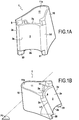
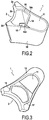
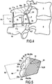
- the first example of an implantable vertebral arthrodesis device 1 for the fusion of two supra and underlying vertebrae shown in FIGS. Figures 1A, 1B , 2, 3 and 4 comprises an anterior portion 2 comprising an upper bearing zone 2a adapted to receive, at least in part, the lower portion 3 of the upper blade 4 of the overlying vertebra 5 and a lower bearing zone 2b adapted to receive the upper portion 6 of the lower blade 7 of the underlying vertebra 8 , the upper 2a and lower 2b support areas being spaced a minimum height h1 for maintaining an intervertebral gap.
- the implantable device 1 also comprises rigid retaining means 9 arranged with respect to the anterior part 2 so as to block the migration of said anterior part 2 towards the spinal canal.
- the implantable device 1 also comprises a posterior portion 10 , in connection with said anterior portion 2 , comprising a main housing 11 having first 11a and second 11b openings facing each other and able to partially receive the spinous processes upper 12 and lower 13 respectively overlying vertebrae 5 and underlying 8.
- the main housing 11 is filled at the time of implantation of a granular osteosynthesis material (not shown).
- anterior 2 and posterior 10 parts are rigid.
- the implantable device 1 comprises a rigid partitioning element 14 disposed between the anterior portion 2 and the posterior portion 10 , in particular in a plane substantially parallel to the plane in which the anterior portion 2 is disposed.
- the retaining means 9 are in the extension of the posterior part 10 , in line with the anterior part 2 , as can be seen in FIG. figure 2 .
- the partition element 14 delimits at least in part with the front portion 2 an auxiliary housing 15 having first 15a and second 15b openings facing each other, said auxiliary housing 15 receiving in operation an osteosynthesis material granular (not shown), and arranged so as to receive in part the blades 4,7 of said overlying vertebra 5 and underlying 8 .
- the front part 2 comprises first and second 2c 2d side edges in conjunction with the first 14c and second 14d side edges of the partition member 14 respectively via first 16 and second 17 lateral portions.
- the first 16 and second 17 side portions diverge towards the anterior portion 2 .
- the partition element 14 has a general U shape, as can be seen in FIG. figure 3 .
- the posterior portion 10 , the retaining means 9 , the partitioning element 14 and the posterior portion 2 are in a molded part, for example PEEK or hydroxyapatite.
- the upper bearing zone 2a of the front portion 2 has a convex shape; preferably the lower bearing zone 2b of the front portion 2 has a concave shape.
- the anterior portion 2 has a concave 2nd anterior face.
- the front part 2 is inclined towards said partition element 14 , in particular forms an angle ⁇ 1 with the support plane (P1) on which the implantable device 1, ⁇ 1 is less than 90 °, preferably between 45 ° and 90 °.
- the lower bearing zone 2b of the front part 2 comprises first 50 and second 51 feet inclined towards the main housing 11.
- the granular bone material is disposed in the auxiliary housing 15 and lead 11, preferably so as to exceed said housing 11,15 to compensate for the withdrawal of 20% by volume observed.
- the implantable device 1 is then placed between the blades 4,7 to the front part 2 and between the spinous processes 12 and lower than 13 for the rear portion 10, as shown in figure 4 .
- the spinous processes 12, 13 are optionally notched, as shown in FIG. figure 4 , so as to better penetrate into said main housing 11 and to come into contact with the osteosynthesis material.
- the anterior part 2 makes it possible to adjust an intervertebral spacing.
- the partitioning element 14 improves the stability of the anterior portion 2 and prevents it from tilting towards the spinous processes 12,13.
- the surface of contact between the material for osteosynthesis with the upper blade 4 and lower 7 on the one hand, and the spinous processes 12 and upper bottom 13 on the other hand, is important, which promotes bone fusion beyond only spinous processes 12,13.
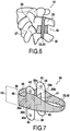
- the second example of an implantable device 18 shown in FIGS. figures 5 and 6 will be described hereinafter only by its differences with the first example of implantable device 1.
- the rear portion 19 is in a foldable material, in particular in a foldable strip 20 , the first end 20a and the second end 20b are respectively secured with the first 25a and second 25b edges of said partition member 25, and respectively at the first 21 and second 22 side portions connecting the first 23a and second 23b side edges from the front portion 23 to the edges 25a and 25b of said partition member 25.
- the anterior portion 23 allows the maintenance of a vertebral distance of a height h2 via the upper 23c and lower 23d support areas.
- the retaining means 24 are here supported by the partitioning element 25.
- the partitioning element 25 and the retaining means 24 thus have a generally U-shaped shape.
- the anterior part 23, the partitioning element 25 and the means In this example, the retaining portions 24 are rigid and in one piece, for example PEEK or molded hydroxyapatite.
- the second exemplary implantable device 18 is disposed between the above 26 and underlying vertebrae 27 in the same manner as the first example of implantable device 1.
- the main housing 28 being in a foldable material, such as in a panel textile, allows the spinous processes 29,30 to come into closer contact with the osteosynthesis material during lordosis movements of the spine, which promotes the activation of the bone graft and the formation of bone fusion.
- the figure 6 represents a first exemplary assembly 31 according to the invention comprising the implantable device 18 shown in FIG. figure 5 .
- the assembly 31 thus comprises a posterior fastening means 32 of the upper spinous processes 29 and lower 30 between them.
- the posterior fastening means 32 comprises an elongated element 33 provided with first and second ends and a means for securing said ends together. Said posterior securing means 32 may be removable, as described in FR 2.961.687 A1 .
- the elongate member 32 surrounds the upper 29 and lower 30 spinous processes and the posterior portion 19 comprises a granular osteosynthesis material.
- the elongated element 33 thus contributes to maintaining the granular osteosynthesis material in the main housing 28, particularly when the spine is in extension.
- the third example of implantable device 34 will be described hereinafter only by its differences with the first example of implantable device 1.
- the third example of implantable device 34 comprises a posterior portion 35 and an anterior portion 36, all two in a foldable material.
- the anterior portion 36 is in a foldable strip 38 , the first 38a and second 38b of which are secured respectively to the first edge 39a and the second edge 39b of the retaining means 39.
- the posterior portion 35 is in a foldable strip 40 of which the first 40a and second 40b ends are secured respectively to the first edge 39a and the second edge 39b of the retaining means 39.
- the partitioning element 41 and the retaining means 39 together have a general shape of H.
- the retaining means 39 comprise first 42 and second 43 upper projections and first 44 and second 45 lower projections respectively extending from the first 39a and second 39b side edges of said retaining means 39.
- These projections 42 to 45 are provided with at least one orifice 46 adapted to cooperate with screws (not shown). Said projections 41 to 45 and the screws thus form a posterior securing means 47 of the implantable device 34 to the upper and lower spinous processes.
- a sufficiently compacted osteosynthesis material in the auxiliary housing 48 delimited between the anterior portion 36 and the partitioning element 41 makes it possible to form upper bearing 35a and lower 35b areas able to come into contact with the upper and lower blades and thus maintain a minimum vertebral spacing, corresponding to the minimum height h2 of the front portion 36.
- the deformation at least in part of the auxiliary housing 48 improves bone fusion because the osteosynthesis material is more stimulated by the blades of vertebrae above and underlying the vertebral level to be corrected.
Landscapes
- Health & Medical Sciences (AREA)
- Orthopedic Medicine & Surgery (AREA)
- Neurology (AREA)
- Life Sciences & Earth Sciences (AREA)
- Engineering & Computer Science (AREA)
- Biomedical Technology (AREA)
- Surgery (AREA)
- General Health & Medical Sciences (AREA)
- Veterinary Medicine (AREA)
- Heart & Thoracic Surgery (AREA)
- Public Health (AREA)
- Animal Behavior & Ethology (AREA)
- Molecular Biology (AREA)
- Medical Informatics (AREA)
- Nuclear Medicine, Radiotherapy & Molecular Imaging (AREA)
- Cardiology (AREA)
- Oral & Maxillofacial Surgery (AREA)
- Transplantation (AREA)
- Vascular Medicine (AREA)
- Prostheses (AREA)
Claims (13)
- Implantierbare Vorrichtung zur vertebralen Arthrodese (1, 18, 34) für die Fusion von zwei darüber- und darunterliegenden Wirbeln, umfassend:a. einen vorderen Teil (2, 23, 36) mit einem oberen Anlagebereich (2a, 23c), der geeignet ist, den unteren Teil (3) der oberen Platte (4) des darüberliegenden Wirbels (5) aufzunehmen, sowie einem unteren Anlagebereich (2b, 23d), der geeignet ist, den oberen Teil (6) der unteren Platte (7) des darunterliegenden Wirbels (8) aufzunehmen, wobei der obere (2a) und der untere (2b) Anlagebereich um eine Mindesthöhe h (h1, h2, h3) für das Aufrechterhalten eines Zwischenwirbelabstandes entfernt sind,b. starre Haltemittel (9), die gegenüber dem vorderen Teil (2) angeordnet sind, um das Wandern des vorderen Teils (2) in Richtung des Wirbelkanals zu blockieren,c. einen hinteren Teil (10, 19, 35), in Verbindung mit dem vorderen Teil (2), der eine Hauptaufnahme (11, 28) mit einer ersten (11a) und einer zweiten (11b) Öffnung umfasst, welche einander gegenüberliegen und geeignet sind, die Dornfortsätze (12, 13, 29, 30) des darüberliegenden Wirbels (5, 26) bzw. des darunterliegenden Wirbels (8, 27) teilweise aufzunehmen,dadurch gekennzeichnet, dass sie umfasst:d. ein zwischen dem vorderen Teil (2) und dem hinteren Teil (10) angeordnetes starres Unterteilungselement (14, 25, 41), das wenigstens teilweise mit dem vorderen Teil (2) eine Hilfsaufnahme (15) begrenzt, welche einander gegenüberliegende erste (15a) und zweite (15b) Öffnungen aufweist und derart angeordnet ist, dass sie die Platten (4, 7) der darüberliegenden (5) und darunterliegenden (8) Wirbel teilweise aufnimmt,e. ein körniges Osteosynthesematerial, das in der Hauptaufnahme (11) und der Hilfsaufnahme (15) angeordnet ist.
- Implantierbare Vorrichtung (18, 34) nach Anspruch 1, dadurch gekennzeichnet, dass die Hauptaufnahme (28) aus einem biegsamen Material, vorzugsweise aus einem biegsamen Band (20, 40) besteht, dessen erstes Ende (20a, 40a) und zweites Ende (20b, 40b) mit dem ersten Seitenrand (25a, 39a) bzw. mit dem zweiten Seitenrand (25b, 39b) des vorderen Teils und/oder der Haltemittel (39) und/oder des Unterteilungselements (25) fest verbunden sind.
- Implantierbare Vorrichtung (18) nach dem einen oder dem anderen der Ansprüche 1 und 2, dadurch gekennzeichnet, dass die Haltemittel (24) von dem Unterteilungselement (25) oder dem hinteren Teil getragen sind.
- Implantierbare Vorrichtung (1) nach einem der Ansprüche 1 bis 3, dadurch gekennzeichnet, dass der vordere Teil (2) erste (2c) und zweite (2d) Seitenränder in Verbindung mit den ersten (14c) und zweiten (14d) Seitenrändern des Unterteilungselements (14) mittels eines ersten (16) bzw. eines zweiten (17) Seitenteils umfasst.
- Implantierbare Vorrichtung (1) nach Anspruch 4, dadurch gekennzeichnet, dass der erste (16) und der zweite (17) Seitenteil in Richtung des vorderen Teils (2) auseinanderlaufen.
- Implantierbare Vorrichtung (1, 18, 34) nach einem der Ansprüche 1 bis 5, dadurch gekennzeichnet, dass das Unterteilungselement (14, 25, 41) und eventuell die Haltemittel (24, 39) insgesamt U- oder H-förmig ausgebildet ist oder sind.
- Implantierbare Vorrichtung (1) nach einem der Ansprüche 1 bis 6, dadurch gekennzeichnet, dass der obere Anlagebereich (2a) des vorderen Teils (2) eine konvexe Form aufweist, vorzugsweise der untere Anlagebereich (2b) des vorderen Teils (2) eine konkave Form aufweist.
- Implantierbare Vorrichtung (1) nach einem der Ansprüche 1 bis 7, dadurch gekennzeichnet, dass der vordere Teil (2) eine konkave Vorderseite (2c) aufweist.
- Implantierbare Vorrichtung (1) nach einem der Ansprüche 1 bis 8, dadurch gekennzeichnet, dass der vordere Teil (2) in Richtung des Unterteilungselements (14) geneigt ist.
- Implantierbare Vorrichtung (1) nach einem der Ansprüche 1 bis 9, dadurch gekennzeichnet, dass der untere Anlagebereich (2b) des vorderen Teils (2) einen ersten (50) und einen zweiten (51) Fuß, die in Richtung der Hauptaufnahme (11) geneigt sind, umfasst.
- Implantierbare Vorrichtung (34) nach einem der Ansprüche 1 bis 10, dadurch gekennzeichnet, dass die Haltemittel (39) wenigstens einen ersten oberen Vorsprung (42, 43) und wenigstens einen ersten unteren Vorsprung (44, 45) umfassen, die sich von dem ersten (39a) und/oder von dem zweiten (39b) Seitenrand (Seitenrändern) des Unterteilungselements, und/oder des Halteelements (39), erstrecken und an ihren Enden mit Öffnungen (46) für den Durchgang von Schrauben versehen sind.
- Implantierbare Vorrichtung (18) nach einem der Ansprüche 1 bis 11, dadurch gekennzeichnet, dass der vordere Teil (23), die Haltemittel (24), eventuell der hintere Teil und/oder das Unterteilungselement (25), aus einem Osteosynthesematerial bestehen.
- Anordnung (31), umfassend eine implantierbare Vorrichtung (18) nach einem der Ansprüche 1 bis 12 und ein hinteres Mittel zum festen Verbinden (32) des oberen (29) und des unteren (30) Dornfortsatzes untereinander, vorzugsweise umfasst das hintere Mittel zum festen Verbinden (32) ein langgestrecktes Element (33), das mit einem ersten und einem zweiten Ende und mit einem Mittel zum festen Verbinden der Enden untereinander versehen ist.
Applications Claiming Priority (2)
| Application Number | Priority Date | Filing Date | Title |
|---|---|---|---|
| FR1359691A FR3011458B1 (fr) | 2013-10-07 | 2013-10-07 | Dispositif implantable d'arthrodese vertebrale pour la fusion entre deux vertebres sus et sous-jacentes. |
| PCT/FR2014/052543 WO2015052431A1 (fr) | 2013-10-07 | 2014-10-07 | Dispositif implantable d'arthrodèse vertébrale pour la fusion de deux vertèbres sus et sous jacentes |
Publications (2)
| Publication Number | Publication Date |
|---|---|
| EP3054873A1 EP3054873A1 (de) | 2016-08-17 |
| EP3054873B1 true EP3054873B1 (de) | 2017-10-25 |
Family
ID=50069052
Family Applications (1)
| Application Number | Title | Priority Date | Filing Date |
|---|---|---|---|
| EP14790230.8A Not-in-force EP3054873B1 (de) | 2013-10-07 | 2014-10-07 | Implantierbare vertebrale arthrodesevorrichtung zur fusion zweier darüber und darunter liegender wirbel |
Country Status (5)
| Country | Link |
|---|---|
| US (1) | US9833266B2 (de) |
| EP (1) | EP3054873B1 (de) |
| ES (1) | ES2647153T3 (de) |
| FR (1) | FR3011458B1 (de) |
| WO (1) | WO2015052431A1 (de) |
Families Citing this family (3)
| Publication number | Priority date | Publication date | Assignee | Title |
|---|---|---|---|---|
| CN103857415B (zh) * | 2011-09-01 | 2016-08-17 | A·D·多斯塔 | 由聚四氟乙烯的多孔三维结构体制成的牙科植入物、血管植入物和组织植入物 |
| ITPI20120106A1 (it) * | 2012-10-19 | 2014-04-20 | Giancarlo Guizzardi | Dispositivo e sistema per artrodesi vertebrale |
| FR3083074B1 (fr) * | 2018-06-29 | 2020-09-11 | Cousin Biotech | Dispositif implantable pour la fusion de deux vertebres adjacentes |
Family Cites Families (9)
| Publication number | Priority date | Publication date | Assignee | Title |
|---|---|---|---|---|
| FR2861286B1 (fr) | 2003-10-24 | 2007-07-06 | Cousin Biotech | Support inter-lamaire |
| US7862592B2 (en) * | 2005-12-06 | 2011-01-04 | Nuvasive, Inc. | Methods and apparatus for treating spinal stenosis |
| US7682376B2 (en) * | 2006-01-27 | 2010-03-23 | Warsaw Orthopedic, Inc. | Interspinous devices and methods of use |
| US8834526B2 (en) * | 2006-08-09 | 2014-09-16 | Rolando Garcia | Methods and apparatus for treating spinal stenosis |
| US8292923B1 (en) * | 2008-10-13 | 2012-10-23 | Nuvasive, Inc. | Systems and methods for treating spinal stenosis |
| FR2961687B1 (fr) | 2010-06-23 | 2015-05-22 | Cousin Biotech | Dispositif de maintien a element longiligne adapte pour maintenir un ecartement intervertebral determine |
| US20120215262A1 (en) * | 2011-02-16 | 2012-08-23 | Interventional Spine, Inc. | Spinous process spacer and implantation procedure |
| US10188434B2 (en) | 2012-02-17 | 2019-01-29 | The University Of Toledo | Hybrid multifunctional posterior interspinous fusion device |
| ITPI20120106A1 (it) * | 2012-10-19 | 2014-04-20 | Giancarlo Guizzardi | Dispositivo e sistema per artrodesi vertebrale |
-
2013
- 2013-10-07 FR FR1359691A patent/FR3011458B1/fr not_active Expired - Fee Related
-
2014
- 2014-10-07 WO PCT/FR2014/052543 patent/WO2015052431A1/fr not_active Ceased
- 2014-10-07 US US15/027,282 patent/US9833266B2/en not_active Expired - Fee Related
- 2014-10-07 ES ES14790230.8T patent/ES2647153T3/es active Active
- 2014-10-07 EP EP14790230.8A patent/EP3054873B1/de not_active Not-in-force
Non-Patent Citations (1)
| Title |
|---|
| None * |
Also Published As
| Publication number | Publication date |
|---|---|
| FR3011458A1 (fr) | 2015-04-10 |
| EP3054873A1 (de) | 2016-08-17 |
| WO2015052431A1 (fr) | 2015-04-16 |
| US20160242821A1 (en) | 2016-08-25 |
| FR3011458B1 (fr) | 2017-02-17 |
| ES2647153T3 (es) | 2017-12-19 |
| US9833266B2 (en) | 2017-12-05 |
Similar Documents
| Publication | Publication Date | Title |
|---|---|---|
| FR3048176A1 (fr) | Systeme d'implants d'arthrodese rachidienne | |
| US9198774B2 (en) | Intervertebral disk cage and stabilizer | |
| EP1675513B1 (de) | Klingen-zwischenstütze | |
| US8241329B2 (en) | Device and method for the prevention of multi-level vertebral extension | |
| EP3451976A1 (de) | Vertebrales system, implantat und einsätze für ein vertebrales system | |
| EP1872731B1 (de) | Implantat zur Stabilisierung der Lumbosakralregion | |
| US7018414B2 (en) | Support device for vertebral fusion | |
| FR2727003A1 (fr) | Dispositif de stabilisation anterieure du rachis lombo-sacre | |
| FR2651992A1 (fr) | Implant pour osteosynthese rachidienne dorso-lombaire anterieure destine a la correction de cyphoses. | |
| CN1649552A (zh) | 颈部椎间假体 | |
| FR2977139A1 (fr) | Implant inter-epineux et instrument d’implantation | |
| FR3015221A1 (fr) | Systeme d'implant intravertebral expansible avec fixation pediculaire posterieure | |
| EP0767637A1 (de) | Wirbelgelenkfortsatz-prothese | |
| CN103298422A (zh) | 椎板植入组 | |
| FR2829377A1 (fr) | Entretoise pour arc vertebral | |
| FR2862866A1 (fr) | Prothese discale intervertebrale postero-laterale | |
| EP3054873A1 (de) | Implantierbare vertebrale arthrodesevorrichtung zur fusion zweier darüber und darunter liegender wirbel | |
| EP0793463A1 (de) | Implantat zum verschmelzen zweier angrenzender knochenkörper, insbesondere zweier aufeinanderfolgender wirbel | |
| US20170252182A1 (en) | Endcaps of a corpectomy cage | |
| JP2021520877A (ja) | 頸椎固定外科手術のための一体式インプラントおよび方法 | |
| WO2011054958A1 (fr) | Cage intersomatique mediane | |
| EP2635213B1 (de) | Stabilisatoren, endkappe und verbinder zur unterstützung der stabilisierung eines wirbelsäulenimplantats | |
| US20210045886A1 (en) | Prosthesis for gleno-humeral articulation | |
| TWI400066B (zh) | 具自攻式固定凸體之椎間假體 | |
| EP3493772A1 (de) | Gekrümmte stift zur fixierung von knochen |
Legal Events
| Date | Code | Title | Description |
|---|---|---|---|
| PUAI | Public reference made under article 153(3) epc to a published international application that has entered the european phase |
Free format text: ORIGINAL CODE: 0009012 |
|
| 17P | Request for examination filed |
Effective date: 20160307 |
|
| AK | Designated contracting states |
Kind code of ref document: A1 Designated state(s): AL AT BE BG CH CY CZ DE DK EE ES FI FR GB GR HR HU IE IS IT LI LT LU LV MC MK MT NL NO PL PT RO RS SE SI SK SM TR |
|
| AX | Request for extension of the european patent |
Extension state: BA ME |
|
| DAX | Request for extension of the european patent (deleted) | ||
| GRAP | Despatch of communication of intention to grant a patent |
Free format text: ORIGINAL CODE: EPIDOSNIGR1 |
|
| INTG | Intention to grant announced |
Effective date: 20170526 |
|
| GRAS | Grant fee paid |
Free format text: ORIGINAL CODE: EPIDOSNIGR3 |
|
| GRAA | (expected) grant |
Free format text: ORIGINAL CODE: 0009210 |
|
| AK | Designated contracting states |
Kind code of ref document: B1 Designated state(s): AL AT BE BG CH CY CZ DE DK EE ES FI FR GB GR HR HU IE IS IT LI LT LU LV MC MK MT NL NO PL PT RO RS SE SI SK SM TR |
|
| REG | Reference to a national code |
Ref country code: GB Ref legal event code: FG4D Free format text: NOT ENGLISH |
|
| REG | Reference to a national code |
Ref country code: CH Ref legal event code: EP |
|
| REG | Reference to a national code |
Ref country code: AT Ref legal event code: REF Ref document number: 939159 Country of ref document: AT Kind code of ref document: T Effective date: 20171115 |
|
| REG | Reference to a national code |
Ref country code: IE Ref legal event code: FG4D Free format text: LANGUAGE OF EP DOCUMENT: FRENCH |
|
| REG | Reference to a national code |
Ref country code: DE Ref legal event code: R096 Ref document number: 602014016369 Country of ref document: DE |
|
| REG | Reference to a national code |
Ref country code: ES Ref legal event code: FG2A Ref document number: 2647153 Country of ref document: ES Kind code of ref document: T3 Effective date: 20171219 |
|
| REG | Reference to a national code |
Ref country code: NL Ref legal event code: MP Effective date: 20171025 |
|
| REG | Reference to a national code |
Ref country code: LT Ref legal event code: MG4D |
|
| REG | Reference to a national code |
Ref country code: AT Ref legal event code: MK05 Ref document number: 939159 Country of ref document: AT Kind code of ref document: T Effective date: 20171025 |
|
| PG25 | Lapsed in a contracting state [announced via postgrant information from national office to epo] |
Ref country code: NL Free format text: LAPSE BECAUSE OF FAILURE TO SUBMIT A TRANSLATION OF THE DESCRIPTION OR TO PAY THE FEE WITHIN THE PRESCRIBED TIME-LIMIT Effective date: 20171025 |
|
| PG25 | Lapsed in a contracting state [announced via postgrant information from national office to epo] |
Ref country code: LT Free format text: LAPSE BECAUSE OF FAILURE TO SUBMIT A TRANSLATION OF THE DESCRIPTION OR TO PAY THE FEE WITHIN THE PRESCRIBED TIME-LIMIT Effective date: 20171025 Ref country code: SE Free format text: LAPSE BECAUSE OF FAILURE TO SUBMIT A TRANSLATION OF THE DESCRIPTION OR TO PAY THE FEE WITHIN THE PRESCRIBED TIME-LIMIT Effective date: 20171025 Ref country code: FI Free format text: LAPSE BECAUSE OF FAILURE TO SUBMIT A TRANSLATION OF THE DESCRIPTION OR TO PAY THE FEE WITHIN THE PRESCRIBED TIME-LIMIT Effective date: 20171025 Ref country code: NO Free format text: LAPSE BECAUSE OF FAILURE TO SUBMIT A TRANSLATION OF THE DESCRIPTION OR TO PAY THE FEE WITHIN THE PRESCRIBED TIME-LIMIT Effective date: 20180125 |
|
| PG25 | Lapsed in a contracting state [announced via postgrant information from national office to epo] |
Ref country code: RS Free format text: LAPSE BECAUSE OF FAILURE TO SUBMIT A TRANSLATION OF THE DESCRIPTION OR TO PAY THE FEE WITHIN THE PRESCRIBED TIME-LIMIT Effective date: 20171025 Ref country code: AT Free format text: LAPSE BECAUSE OF FAILURE TO SUBMIT A TRANSLATION OF THE DESCRIPTION OR TO PAY THE FEE WITHIN THE PRESCRIBED TIME-LIMIT Effective date: 20171025 Ref country code: BG Free format text: LAPSE BECAUSE OF FAILURE TO SUBMIT A TRANSLATION OF THE DESCRIPTION OR TO PAY THE FEE WITHIN THE PRESCRIBED TIME-LIMIT Effective date: 20180125 Ref country code: LV Free format text: LAPSE BECAUSE OF FAILURE TO SUBMIT A TRANSLATION OF THE DESCRIPTION OR TO PAY THE FEE WITHIN THE PRESCRIBED TIME-LIMIT Effective date: 20171025 Ref country code: IS Free format text: LAPSE BECAUSE OF FAILURE TO SUBMIT A TRANSLATION OF THE DESCRIPTION OR TO PAY THE FEE WITHIN THE PRESCRIBED TIME-LIMIT Effective date: 20180225 Ref country code: GR Free format text: LAPSE BECAUSE OF FAILURE TO SUBMIT A TRANSLATION OF THE DESCRIPTION OR TO PAY THE FEE WITHIN THE PRESCRIBED TIME-LIMIT Effective date: 20180126 Ref country code: HR Free format text: LAPSE BECAUSE OF FAILURE TO SUBMIT A TRANSLATION OF THE DESCRIPTION OR TO PAY THE FEE WITHIN THE PRESCRIBED TIME-LIMIT Effective date: 20171025 |
|
| REG | Reference to a national code |
Ref country code: DE Ref legal event code: R097 Ref document number: 602014016369 Country of ref document: DE |
|
| PG25 | Lapsed in a contracting state [announced via postgrant information from national office to epo] |
Ref country code: CY Free format text: LAPSE BECAUSE OF FAILURE TO SUBMIT A TRANSLATION OF THE DESCRIPTION OR TO PAY THE FEE WITHIN THE PRESCRIBED TIME-LIMIT Effective date: 20171025 Ref country code: CZ Free format text: LAPSE BECAUSE OF FAILURE TO SUBMIT A TRANSLATION OF THE DESCRIPTION OR TO PAY THE FEE WITHIN THE PRESCRIBED TIME-LIMIT Effective date: 20171025 Ref country code: SK Free format text: LAPSE BECAUSE OF FAILURE TO SUBMIT A TRANSLATION OF THE DESCRIPTION OR TO PAY THE FEE WITHIN THE PRESCRIBED TIME-LIMIT Effective date: 20171025 Ref country code: EE Free format text: LAPSE BECAUSE OF FAILURE TO SUBMIT A TRANSLATION OF THE DESCRIPTION OR TO PAY THE FEE WITHIN THE PRESCRIBED TIME-LIMIT Effective date: 20171025 Ref country code: DK Free format text: LAPSE BECAUSE OF FAILURE TO SUBMIT A TRANSLATION OF THE DESCRIPTION OR TO PAY THE FEE WITHIN THE PRESCRIBED TIME-LIMIT Effective date: 20171025 |
|
| PG25 | Lapsed in a contracting state [announced via postgrant information from national office to epo] |
Ref country code: PL Free format text: LAPSE BECAUSE OF FAILURE TO SUBMIT A TRANSLATION OF THE DESCRIPTION OR TO PAY THE FEE WITHIN THE PRESCRIBED TIME-LIMIT Effective date: 20171025 Ref country code: RO Free format text: LAPSE BECAUSE OF FAILURE TO SUBMIT A TRANSLATION OF THE DESCRIPTION OR TO PAY THE FEE WITHIN THE PRESCRIBED TIME-LIMIT Effective date: 20171025 Ref country code: SM Free format text: LAPSE BECAUSE OF FAILURE TO SUBMIT A TRANSLATION OF THE DESCRIPTION OR TO PAY THE FEE WITHIN THE PRESCRIBED TIME-LIMIT Effective date: 20171025 |
|
| PLBE | No opposition filed within time limit |
Free format text: ORIGINAL CODE: 0009261 |
|
| STAA | Information on the status of an ep patent application or granted ep patent |
Free format text: STATUS: NO OPPOSITION FILED WITHIN TIME LIMIT |
|
| PG25 | Lapsed in a contracting state [announced via postgrant information from national office to epo] |
Ref country code: MT Free format text: LAPSE BECAUSE OF FAILURE TO SUBMIT A TRANSLATION OF THE DESCRIPTION OR TO PAY THE FEE WITHIN THE PRESCRIBED TIME-LIMIT Effective date: 20171025 |
|
| 26N | No opposition filed |
Effective date: 20180726 |
|
| REG | Reference to a national code |
Ref country code: FR Ref legal event code: PLFP Year of fee payment: 5 |
|
| PG25 | Lapsed in a contracting state [announced via postgrant information from national office to epo] |
Ref country code: SI Free format text: LAPSE BECAUSE OF FAILURE TO SUBMIT A TRANSLATION OF THE DESCRIPTION OR TO PAY THE FEE WITHIN THE PRESCRIBED TIME-LIMIT Effective date: 20171025 |
|
| REG | Reference to a national code |
Ref country code: CH Ref legal event code: PL |
|
| REG | Reference to a national code |
Ref country code: BE Ref legal event code: MM Effective date: 20181031 |
|
| PG25 | Lapsed in a contracting state [announced via postgrant information from national office to epo] |
Ref country code: MC Free format text: LAPSE BECAUSE OF FAILURE TO SUBMIT A TRANSLATION OF THE DESCRIPTION OR TO PAY THE FEE WITHIN THE PRESCRIBED TIME-LIMIT Effective date: 20171025 Ref country code: LU Free format text: LAPSE BECAUSE OF NON-PAYMENT OF DUE FEES Effective date: 20181007 |
|
| REG | Reference to a national code |
Ref country code: IE Ref legal event code: MM4A |
|
| PG25 | Lapsed in a contracting state [announced via postgrant information from national office to epo] |
Ref country code: CH Free format text: LAPSE BECAUSE OF NON-PAYMENT OF DUE FEES Effective date: 20181031 Ref country code: BE Free format text: LAPSE BECAUSE OF NON-PAYMENT OF DUE FEES Effective date: 20181031 Ref country code: LI Free format text: LAPSE BECAUSE OF NON-PAYMENT OF DUE FEES Effective date: 20181031 |
|
| PG25 | Lapsed in a contracting state [announced via postgrant information from national office to epo] |
Ref country code: IE Free format text: LAPSE BECAUSE OF NON-PAYMENT OF DUE FEES Effective date: 20181007 |
|
| PG25 | Lapsed in a contracting state [announced via postgrant information from national office to epo] |
Ref country code: TR Free format text: LAPSE BECAUSE OF FAILURE TO SUBMIT A TRANSLATION OF THE DESCRIPTION OR TO PAY THE FEE WITHIN THE PRESCRIBED TIME-LIMIT Effective date: 20171025 |
|
| PG25 | Lapsed in a contracting state [announced via postgrant information from national office to epo] |
Ref country code: PT Free format text: LAPSE BECAUSE OF FAILURE TO SUBMIT A TRANSLATION OF THE DESCRIPTION OR TO PAY THE FEE WITHIN THE PRESCRIBED TIME-LIMIT Effective date: 20171025 |
|
| PG25 | Lapsed in a contracting state [announced via postgrant information from national office to epo] |
Ref country code: HU Free format text: LAPSE BECAUSE OF FAILURE TO SUBMIT A TRANSLATION OF THE DESCRIPTION OR TO PAY THE FEE WITHIN THE PRESCRIBED TIME-LIMIT; INVALID AB INITIO Effective date: 20141007 Ref country code: MK Free format text: LAPSE BECAUSE OF NON-PAYMENT OF DUE FEES Effective date: 20171025 |
|
| PG25 | Lapsed in a contracting state [announced via postgrant information from national office to epo] |
Ref country code: AL Free format text: LAPSE BECAUSE OF FAILURE TO SUBMIT A TRANSLATION OF THE DESCRIPTION OR TO PAY THE FEE WITHIN THE PRESCRIBED TIME-LIMIT Effective date: 20171025 |
|
| PGFP | Annual fee paid to national office [announced via postgrant information from national office to epo] |
Ref country code: ES Payment date: 20211105 Year of fee payment: 8 Ref country code: GB Payment date: 20211020 Year of fee payment: 8 Ref country code: DE Payment date: 20211008 Year of fee payment: 8 |
|
| PGFP | Annual fee paid to national office [announced via postgrant information from national office to epo] |
Ref country code: IT Payment date: 20211008 Year of fee payment: 8 Ref country code: FR Payment date: 20211022 Year of fee payment: 8 |
|
| REG | Reference to a national code |
Ref country code: DE Ref legal event code: R082 Ref document number: 602014016369 Country of ref document: DE Representative=s name: CBDL PATENTANWAELTE GBR, DE |
|
| REG | Reference to a national code |
Ref country code: DE Ref legal event code: R119 Ref document number: 602014016369 Country of ref document: DE |
|
| GBPC | Gb: european patent ceased through non-payment of renewal fee |
Effective date: 20221007 |
|
| PG25 | Lapsed in a contracting state [announced via postgrant information from national office to epo] |
Ref country code: FR Free format text: LAPSE BECAUSE OF NON-PAYMENT OF DUE FEES Effective date: 20221031 Ref country code: DE Free format text: LAPSE BECAUSE OF NON-PAYMENT OF DUE FEES Effective date: 20230503 |
|
| PG25 | Lapsed in a contracting state [announced via postgrant information from national office to epo] |
Ref country code: IT Free format text: LAPSE BECAUSE OF NON-PAYMENT OF DUE FEES Effective date: 20221007 Ref country code: GB Free format text: LAPSE BECAUSE OF NON-PAYMENT OF DUE FEES Effective date: 20221007 |
|
| REG | Reference to a national code |
Ref country code: ES Ref legal event code: FD2A Effective date: 20231127 |
|
| PG25 | Lapsed in a contracting state [announced via postgrant information from national office to epo] |
Ref country code: ES Free format text: LAPSE BECAUSE OF NON-PAYMENT OF DUE FEES Effective date: 20221008 |
|
| PG25 | Lapsed in a contracting state [announced via postgrant information from national office to epo] |
Ref country code: ES Free format text: LAPSE BECAUSE OF NON-PAYMENT OF DUE FEES Effective date: 20221008 |