EP3054079A1 - Drilling rig mast erection system and method - Google Patents
Drilling rig mast erection system and method Download PDFInfo
- Publication number
- EP3054079A1 EP3054079A1 EP16154057.0A EP16154057A EP3054079A1 EP 3054079 A1 EP3054079 A1 EP 3054079A1 EP 16154057 A EP16154057 A EP 16154057A EP 3054079 A1 EP3054079 A1 EP 3054079A1
- Authority
- EP
- European Patent Office
- Prior art keywords
- mast
- substructure
- drilling rig
- support
- pinned connection
- Prior art date
- Legal status (The legal status is an assumption and is not a legal conclusion. Google has not performed a legal analysis and makes no representation as to the accuracy of the status listed.)
- Withdrawn
Links
Images


Classifications
-
- E—FIXED CONSTRUCTIONS
- E21—EARTH DRILLING; MINING
- E21B—EARTH DRILLING, e.g. DEEP DRILLING; OBTAINING OIL, GAS, WATER, SOLUBLE OR MELTABLE MATERIALS OR A SLURRY OF MINERALS FROM WELLS
- E21B7/00—Special methods or apparatus for drilling
- E21B7/02—Drilling rigs characterized by means for land transport with their own drive, e.g. skid mounting or wheel mounting
- E21B7/023—Drilling rigs characterized by means for land transport with their own drive, e.g. skid mounting or wheel mounting the mast being foldable or telescopically retractable
-
- E—FIXED CONSTRUCTIONS
- E04—BUILDING
- E04B—GENERAL BUILDING CONSTRUCTIONS; WALLS, e.g. PARTITIONS; ROOFS; FLOORS; CEILINGS; INSULATION OR OTHER PROTECTION OF BUILDINGS
- E04B1/00—Constructions in general; Structures which are not restricted either to walls, e.g. partitions, or floors or ceilings or roofs
- E04B1/35—Extraordinary methods of construction, e.g. lift-slab, jack-block
- E04B1/3533—Extraordinary methods of construction, e.g. lift-slab, jack-block characterised by the raising of hingedly-connected building elements, e.g. arches, portal frames
-
- E—FIXED CONSTRUCTIONS
- E04—BUILDING
- E04H—BUILDINGS OR LIKE STRUCTURES FOR PARTICULAR PURPOSES; SWIMMING OR SPLASH BATHS OR POOLS; MASTS; FENCING; TENTS OR CANOPIES, IN GENERAL
- E04H12/00—Towers; Masts or poles; Chimney stacks; Water-towers; Methods of erecting such structures
- E04H12/18—Towers; Masts or poles; Chimney stacks; Water-towers; Methods of erecting such structures movable or with movable sections, e.g. rotatable or telescopic
- E04H12/182—Towers; Masts or poles; Chimney stacks; Water-towers; Methods of erecting such structures movable or with movable sections, e.g. rotatable or telescopic telescopic
-
- E—FIXED CONSTRUCTIONS
- E04—BUILDING
- E04H—BUILDINGS OR LIKE STRUCTURES FOR PARTICULAR PURPOSES; SWIMMING OR SPLASH BATHS OR POOLS; MASTS; FENCING; TENTS OR CANOPIES, IN GENERAL
- E04H12/00—Towers; Masts or poles; Chimney stacks; Water-towers; Methods of erecting such structures
- E04H12/18—Towers; Masts or poles; Chimney stacks; Water-towers; Methods of erecting such structures movable or with movable sections, e.g. rotatable or telescopic
- E04H12/187—Towers; Masts or poles; Chimney stacks; Water-towers; Methods of erecting such structures movable or with movable sections, e.g. rotatable or telescopic with hinged sections
-
- E—FIXED CONSTRUCTIONS
- E04—BUILDING
- E04H—BUILDINGS OR LIKE STRUCTURES FOR PARTICULAR PURPOSES; SWIMMING OR SPLASH BATHS OR POOLS; MASTS; FENCING; TENTS OR CANOPIES, IN GENERAL
- E04H12/00—Towers; Masts or poles; Chimney stacks; Water-towers; Methods of erecting such structures
- E04H12/34—Arrangements for erecting or lowering towers, masts, poles, chimney stacks, or the like
- E04H12/345—Arrangements for tilting up whole structures or sections thereof
-
- E—FIXED CONSTRUCTIONS
- E21—EARTH DRILLING; MINING
- E21B—EARTH DRILLING, e.g. DEEP DRILLING; OBTAINING OIL, GAS, WATER, SOLUBLE OR MELTABLE MATERIALS OR A SLURRY OF MINERALS FROM WELLS
- E21B15/00—Supports for the drilling machine, e.g. derricks or masts
-
- E—FIXED CONSTRUCTIONS
- E21—EARTH DRILLING; MINING
- E21B—EARTH DRILLING, e.g. DEEP DRILLING; OBTAINING OIL, GAS, WATER, SOLUBLE OR MELTABLE MATERIALS OR A SLURRY OF MINERALS FROM WELLS
- E21B15/00—Supports for the drilling machine, e.g. derricks or masts
- E21B15/003—Supports for the drilling machine, e.g. derricks or masts adapted to be moved on their substructure, e.g. with skidding means; adapted to drill a plurality of wells
-
- E—FIXED CONSTRUCTIONS
- E21—EARTH DRILLING; MINING
- E21B—EARTH DRILLING, e.g. DEEP DRILLING; OBTAINING OIL, GAS, WATER, SOLUBLE OR MELTABLE MATERIALS OR A SLURRY OF MINERALS FROM WELLS
- E21B15/00—Supports for the drilling machine, e.g. derricks or masts
- E21B15/006—Means for anchoring the drilling machine to the ground
-
- E—FIXED CONSTRUCTIONS
- E21—EARTH DRILLING; MINING
- E21B—EARTH DRILLING, e.g. DEEP DRILLING; OBTAINING OIL, GAS, WATER, SOLUBLE OR MELTABLE MATERIALS OR A SLURRY OF MINERALS FROM WELLS
- E21B15/00—Supports for the drilling machine, e.g. derricks or masts
- E21B15/04—Supports for the drilling machine, e.g. derricks or masts specially adapted for directional drilling, e.g. slant hole rigs
- E21B15/045—Hydraulic, pneumatic or electric circuits for their positioning
-
- E—FIXED CONSTRUCTIONS
- E21—EARTH DRILLING; MINING
- E21B—EARTH DRILLING, e.g. DEEP DRILLING; OBTAINING OIL, GAS, WATER, SOLUBLE OR MELTABLE MATERIALS OR A SLURRY OF MINERALS FROM WELLS
- E21B7/00—Special methods or apparatus for drilling
- E21B7/02—Drilling rigs characterized by means for land transport with their own drive, e.g. skid mounting or wheel mounting
-
- E—FIXED CONSTRUCTIONS
- E04—BUILDING
- E04B—GENERAL BUILDING CONSTRUCTIONS; WALLS, e.g. PARTITIONS; ROOFS; FLOORS; CEILINGS; INSULATION OR OTHER PROTECTION OF BUILDINGS
- E04B1/00—Constructions in general; Structures which are not restricted either to walls, e.g. partitions, or floors or ceilings or roofs
- E04B1/35—Extraordinary methods of construction, e.g. lift-slab, jack-block
- E04B1/3522—Extraordinary methods of construction, e.g. lift-slab, jack-block characterised by raising a structure and then adding structural elements under it
-
- E—FIXED CONSTRUCTIONS
- E04—BUILDING
- E04B—GENERAL BUILDING CONSTRUCTIONS; WALLS, e.g. PARTITIONS; ROOFS; FLOORS; CEILINGS; INSULATION OR OTHER PROTECTION OF BUILDINGS
- E04B1/00—Constructions in general; Structures which are not restricted either to walls, e.g. partitions, or floors or ceilings or roofs
- E04B1/35—Extraordinary methods of construction, e.g. lift-slab, jack-block
- E04B2001/3588—Extraordinary methods of construction, e.g. lift-slab, jack-block using special lifting or handling devices, e.g. gantries, overhead conveying rails
-
- E—FIXED CONSTRUCTIONS
- E04—BUILDING
- E04H—BUILDINGS OR LIKE STRUCTURES FOR PARTICULAR PURPOSES; SWIMMING OR SPLASH BATHS OR POOLS; MASTS; FENCING; TENTS OR CANOPIES, IN GENERAL
- E04H12/00—Towers; Masts or poles; Chimney stacks; Water-towers; Methods of erecting such structures
- E04H2012/006—Structures with truss-like sections combined with tubular-like sections
Definitions
- the present subject matter is generally directed to mobile drilling rig assemblies, and in particular, to a substructure of a mobile drilling rig having telescoping substructure boxes to facilitate drilling rig assembly and erection.
- drilling rigs are delivered to an oilfield drilling site by transporting the various components of the drilling rig over roads and/or highways.
- the various drilling rig components are transported to a drilling site on one or more truck/trailer combinations, the number of which may depend on the size, weight, and complexity of the rig.
- the drilling rig components are then assembled, and the drilling rig assembly is raised to an operating position so as to perform drilling operations.
- the mobile drilling rig is then lowered, disassembled, loaded back onto truck/trailer combinations, and transported to a different oilfield drilling site for new drilling operations. Accordingly, the ease with which the various drilling rig components can be transported, assembled and disassembled, and raised and lowered can be a substantial factor in the drilling rig design, as well as the rig's overall operational capabilities and cost effectiveness.
- a typical drawworks for a 2000 HP mobile rig may weigh in the range of 80-100 thousand pounds, or even more.
- individual sections of a drilling rig mast may be 30-40 feet or more in length, and may weigh 20-80 thousand pounds each. In many cases, such large and heavy components require the use of a suitably sized crane so as to lift and position the various drilling components during rig assembly.
- the overall logistical considerations for using at least some higher capacity mobile drilling rigs may need to include having a crane present at a given drilling site prior to the commencement of drilling operations in order to facilitate initial rig assembly.
- a crane may also need to be present after the completion of drilling operations so as to facilitate rig disassembly for transportation to other oilfield drilling sites.
- the requirement that a crane be used during these assembly/disassembly stages can have a significant impact on the overall cost of the drilling operation, as well as the amount of time that may be needed to perform the operations.
- drilling operations at a given oilfield drilling site may involve drilling a plurality of relatively closely spaced wellbores, sometimes referred to as "pad" drilling.
- the distance between adjacent wellbores may be as little as 20-30 feet, or even less, and are oftentimes arranged in a two-dimensional grid pattern, such that rows and columns of wellbores are disposed along lines that run substantially parallel to an x-axis and a y-axis, respectively.
- pad drilling applications after drilling operations have been completed at one wellbore, it is necessary to move the drilling rig to an adjacent wellbore, which can be quite costly and time consuming when a crane is required to disassemble, lift, and move the various drilling rig components to the next wellbore location before drilling operations can commence.
- such moving devices are generally only capable of being moved substantially along a single axis, e.g., along an x-axis or along a y-axis. Accordingly, while it may be feasible to trailer such a mobile drilling rig in an axial direction between closely-spaced adjacent wellbores that are disposed along the same column or row of wellbores making up the grid pattern at a given pad drilling site, it is generally not possible to move the mobile drilling rig laterally or longitudinally, e.g., from row to row or from column to column, when using conventional wheeled trailers or dollies.
- the subject matter disclosed herein relates to various aspects of a telescoping substructure of a mobile drilling rig that can be collapsed for transportation over highways and/or roads to an oilfield drilling site, and which can also be telescoped, i.e., raised or lowered, as necessary to facilitate assembly of the mobile drilling rig without the use of traditional stand-alone cranes.
- the telescoping substructure of the present disclosure may be used in conjunction with a mast positioning apparatus during rig assembly to facilitate the positioning of a drilling rig mast above the drilling floor of the mobile drilling rig, and the proper alignment of the drilling rig mast connections with the mast support shoes on the telescoping substructure without the use of a crane.
- substructure raising means and rig moving means may be used to facilitate skid movement of the fully assembled and erected mobile drilling rig between adjacent wellbore locations during pad drilling operations, thereby avoiding the use of heavy lift cranes for disassembly of the rig prior to rig movement.
- a telescoping substructure of a drilling rig includes first and second telescoping substructure boxes.
- the first and second telescoping substructure boxes each include, among other things, a lower substructure box and an upper substructure box that is adapted to be telescopically raised and lowered relative to the lower substructure box.
- each telescoping substructure box also includes raising means for telescopically raising and lowering the upper substructure box relative to the lower substructure box between a collapsed configuration for transportation and a raised configuration for drilling operations, wherein each of the first and second telescoping substructure boxes are adapted to facilitate movement of the telescoping substructure in at least one of a lateral direction and a longitudinal direction over wellhead equipment positioned above a wellbore location when the upper substructure boxes are in the raised configuration.
- Also disclosed herein is an illustrative method that includes, among other things, positioning a first telescoping substructure box adjacent to and laterally spaced apart from a second telescoping substructure box, the first and second telescoping substructure boxes each having an upper substructure box, a lower substructure box, and raising means for telescopically raising and lowering the respective first and second telescoping substructure boxes.
- the disclosed method further includes telescopically raising the laterally spaced apart first and second telescoping substructure boxes to a raised configuration for drilling operations by telescopically raising, with the raising means, the upper substructure boxes relative to the respective lower substructure boxes, and performing drilling operations with a drilling rig comprising the first and second telescoping substructure boxes on a first wellbore location positioned between the laterally spaced apart first and second telescoping substructure boxes. Additionally, the disclosed method also includes moving the drilling rig from the first wellbore location to a second wellbore location while the first and second telescoping substructure boxes are in the raised configuration and while pressure-retaining equipment is positioned above at least one of the first and second wellbore locations.
- a drilling rig mast erection system in another illustrative embodiment, includes, among other things, a mast support shoe fixedly attached to a drilling rig substructure, the mast support shoe having a first pinned connection. Furthermore, the drilling rig mast erection system also includes a bottom mast section of a drilling rig mast, the bottom mast section having a second pinned connection that is adapted to be pivotably connected to the first pinned connection of the mast support shoe. Moreover, the disclosed mast erection system includes a mast positioning apparatus that is adapted to pivotably position the bottom mast section so that the second pinned connection of the bottom mast section is positioned adjacent to the first pinned connection of the mast support shoe.
- Yet another exemplary embodiment of the present disclosure is a method for erecting a drilling rig mast that includes, among other things, pivotably connecting a first end of bottom mast support spreader to a bottom mast section of the drilling rig mast and pivotably rotating the bottom mast support spreader about a second end of the bottom mast support spreader to pivotably position a first pinned connection of the bottom mast section adjacent to a second pinned connection of a mast support shoe.
- the disclosed method further includes pivotably connecting the first pinned connection of the bottom mast section to the second pinned connection of the mast support shoe.
- the subject matter disclosed herein is directed to mobile drilling rig assemblies having telescoping substructure boxes, which may be used to facilitate the assembly and installation of large and/or heavy drilling rig components, such as a drilling rig mast, rig drawworks, driller's cabin, and the like, without relying on the use of a stand-alone crane to lift and/or position the various rig components.
- a mast positioning apparatus is disclosed herein that may be used to position the drilling rig mast adjacent to the mast support shoes on the drilling floor while the telescoping substructure boxes are in a collapsed configuration, thereby allowing the mast to be pivotably attached to mast support shoes in preparation for mast erection.
- substructure raising apparatuses may be used to telescope, i.e., raise and lower, the telescoping substructure boxes during drilling rig assembly, as well as lift the assembled mobile drilling rig for skid movement between adjacent wellbore locations during pad drilling operations.
- Figures 1A and 1B are side and end elevation views, respectively, of an illustrative mobile drilling rig 300 accordingly to the present disclosure that generally includes a driller's side 300a, an off-driller's side 300b, a drawworks side 300c, and a setback side 300d. More specifically, Fig. 1A is an elevation view of the rig 300 when viewed from the driller's side 300a of the rig 300, and Fig. 1B is an elevation view of the rig 300 when viewed from the setback side 300d, or front side, of the rig 300. As shown in the illustrative embodiment depicted in Figs.
- the mobile drilling rig 300 may include, among other things, a telescoping substructure 100 and a drilling rig mast 200.
- the telescoping substructure 100 may include a driller's side 300a telescoping substructure box 110 that is made up of an upper substructure box 110u and a lower substructure box 110L, an off-driller's side 300b telescoping substructure box 120 that also includes upper and lower substructure boxes 120u, 120L, and a substructure center floor section 125 positioned between and supported by the upper substructure boxes 110u and 120u.
- each upper substructure box 110u, 120u is operatively coupled to and engages with its respective lower substructure box 110L, 120L in such a manner so as to allow the upper substructure boxes 110u, 120u to be raised and/or lowered relative to the lower substructure boxes 110L, 120L when the telescoping substructure boxes 110, 120 are "telescoped" into different positions, e.g., for rig transportation to a drilling site, drilling operations at the drilling site, and/or rig movement around the drilling site, as will be further described below.
- the upper surfaces of the telescoping substructure 100 e.g., the upper surfaces of the telescoping substructure boxes 110, 120 and the substructure center floor section 125 may form a drilling floor 101 where personnel, as well as materials and equipment, may be present during the various drilling rig operations.
- a drilling rig cellar area 150 is located between the telescoping substructure boxes 110, 120 and below the substructure center floor section 125.
- Pressure-retaining wellhead equipment 160 such as a blowout preventer apparatus and the like, may be positioned in the cellar area 150 above a wellbore location 170, where drilling operations may be performed so as to drill and advance a wellbore below the surface of the ground 190.
- additional wellbore locations may be located closely adjacent to the wellbore location 170.
- a driller's side 300a wellbore location 171 and an off-driller's side 300b wellbore location 172 may be laterally positioned on either side of the wellbore location 170, as shown in Fig. 1B .
- a drawworks side 300c wellbore location 173 and a setback side 300d wellbore location 174 may be longitudinally positioned on either side of the wellbore location 170, as shown in Fig.
- each of the wellbore locations 171-174 may be located at respective distances 171d-174d away from the wellbore location 170, which may be as close as approximately 20 feet or less, or as far away as approximately 100 feet or more. It should be appreciated, however, that other spacing distances may also be used in pad drilling applications. Moreover, it should also be appreciated that the spacing between the wellbore location 170 and each of the adjacent wellbore locations 171-174 need not be uniform, e.g., each of the distances 171 d-174d may be different.
- a drawworks 140 may be attached to the upper substructure boxes 110u, 120u of the telescoping substructure 100, as shown in Fig. 1A .
- the drawworks 140 may be supported by a drawworks skid 141, which may include appropriately designed connections 141 p that are adapted to removably attach the drawworks skid 141 and drawworks 140 to support clips 142 on each of the upper substructure boxes 110u, 120u.
- a driller's side 300a ancillary structure 119 may be removably attached to the driller's side 300a telescoping substructure box 110 as shown in Fig. 1B , which may include, for example, a driller's cabin 119a, and control cabin 119b, and the like.
- an off-driller's side 300b ancillary structure 129 may also be removably attached to the off-driller's side 300b telescoping substructure box 120, which may include, among other things, a wind wall 129a, standpipe manifold 129b, and the like.
- the telescoping substructure 100 may also include means for telescopically raising raise and/or lowering the upper substructure boxes 110u and/or 120u relative to a respective lower substructure box 110L and/or 120L - i.e., means for "telescoping" the substructure boxes 110 and 120 of the telescoping substructure 100 - which in some cases may hereinafter be referred to as "substructure raising apparatuses" 130, for simplicity.
- the substructure raising apparatuses 130 may be adapted to telescopically raise and lower the substructure boxes 110, 120 as may be required for a particular rig assembly, operating, or disassembly stage.
- the substructure raising apparatuses 130 may be adapted to generate a force of sufficient magnitude to raise the upper substructure boxes 110u, 120u above the lower substructure boxes 110L, 120L when the mobile drilling rig 300 is in a fully assembled condition, e.g., including all equipment and structures such as the drilling rig mast 200, drawworks 140, ancillary structures 119 and/or 129, etc.
- the means for raising and lowering the telescoping substructure boxes 110 and 120 may also be used as means for lifting and lowering the substructure boxes 110 and 120 relative to the ground 190, and/or lifting and lowering the fully assembled mobile drilling rig 300 relative to the ground 190, depending on the specific rig assembly, operating, or disassembly stage.
- the means for raising and lowering the telescoping substructure boxes 110, 120 may be used to lift and/or lower the telescoping substructure boxes 110, 120 relative to the ground 190 during an unloading stage after the fully collapsed substructure boxes 110, 120 have been transported to an oilfield drilling site, as will be further described with respect to Figs. 3A-3C below, and/or to re-load the fully collapsed substructure boxes 110, 120 for movement to another oilfield drilling site after rig disassembly.
- the means for raising and lower the telescoping substructure 100 may also be appropriately sized so that the means can be used for lifting and lowering the fully assembled mobile drilling rig 300 relative to the ground 190 so that the rig 300 can be skidded from, for example, the wellbore location 170 to an adjacent wellbore location 171-174, as will also be further discussed with respect to Figs. 7A and 7B below.
- each of the substructure raising apparatuses 130 may be, for example, a telescoping hydraulic and/or pneumatic cylinders, screw and/or gear mechanisms, chain and sprocket arrangements, or cable and pulley/roller arrangements and the like. See, for example, the substructure raising apparatuses 130 shown in Figs. 1A and 1B .
- each substructure raising apparatus 130 (or apparatuses 130) may be attached at an upper end thereof to an appropriately designed structural support member 114 (or members 114) on the respective upper substructure boxes 110u, 120u.
- the substructure raising apparatuses 130 may also have attached at a lower end thereof a respective bearing plate or skid foot 131, which is typically used to transfer the weight of the telescoping substructure 100, or the fully assembled mobile drilling rig 300, to the ground 190 during substructure telescoping (raising and/or lowering) operations. Additionally, in those illustrative embodiments of the mobile drilling rig 300 that are adapted to perform pad drilling operations, means for moving the fully assembled rig 300 may be operatively coupled to the telescoping substructure 100.
- the means for moving the fully assembled mobile drilling rig may include a skid foot movement apparatus 132 that may be positioned between and operatively coupled to each substructure raising apparatus 130 and its respective skid foot 131 so as to facilitate skid movement of the fully assembled rig 300 between adjacent wellbore locations 170 and 171-174, as will be further described with respect to Figs. 7C-7H below.
- Figure 1C is a plan view of the illustrative telescoping substructure 100 taken along the view line "1C-1 C" of Fig. 1B , wherein some elements of the mobile drilling rig 300, such as the drilling rig mast 200 and drilling floor 101 above each of the telescoping substructure boxes 110, 120 have been removed for clarity.
- each of the plurality of substructure raising apparatuses 130 may be positioned near a respective corner of the telescoping substructure 100, i.e., such that one substructure raising apparatus 130 is proximate each end 110e and 120e of the respective telescoping substructure boxes 110 and 120.
- each substructure raising apparatuses 130 may be substantially centered below a respective structural support member 114, as shown in Fig. 1C . Accordingly, each telescoping substructure box 110, 120 may be telescoped, i.e., raised and/or lowered, by actuating the pair of substructure raising apparatuses 130 located at the respective ends 110e, 120e.
- a single substructure raising apparatus 130 is positioned near each corner of the telescoping substructure 100.
- more than one substructure raising apparatus 130 may be used at each respective corner location.
- FIG. 1C illustrates only one structural support member 114 near each corner of the telescoping substructure 100, it should be understood that a plurality of structural support members 114 may be used at each corner location, depending on the specific design and/or quantity of raising apparatuses 130 utilized. For example, in those illustrative embodiments wherein a plurality of raising apparatuses 130, e.g., two or more, are used at each corner location, two or more structural support members 114 may also be used.
- two or more structural support members 114 may be arranged in any appropriate or suitable configuration, such as parallel spaced apart members or cross members and the like, depending on the specific rig design considerations such as the number of raising apparatuses 130, the anticipated lift and/or operating loads for the mobile drilling rig 300, etc.
- the mobile drilling rig 300 may include a drilling rig mast 200 positioned above the telescoping substructure 100 and the drilling floor 101.
- the drilling rig mast 200 may include a bottom mast section 220 and an upper mast section 240.
- the drilling rig mast 200 may be pivotably attached to and supported by mast support shoes 210, which may be fixedly attached, e.g., bolted, to the upper substructure boxes 110u, 120u.
- the drilling rig mast 200 may also be removably attached to and further supported by an A-frame structure 235, as shown in Fig. 1A .
- the front legs of the A-frame structure 235 may be removably attached to and supported by the mast support shoes 210 (see, Fig. 1A ), and the rear legs of the A-frame structure 235 may be removably attached to and supported by respective leg support shoes 211, which may also be fixedly attached to the upper substructure boxes 110u, 120u.
- Figures 2A-2J depict various aspects of an illustrative telescoping substructure box 110, such as the driller's side 300a telescoping substructure box 110 shown in Figs. 1A-1C . It should be understood, however, that while the details described with respect to Figs. 2A-2J are specific to the driller's side 300a telescoping substructure box 110, the following description is also generally applicable to the respective details of an off-driller's side 300b telescoping substructure box 120.
- Figures 2A, 2B, and 2C are end elevation, side elevation, and plan views, respectively, of an illustrative upper substructure box 110u.
- the upper substructure box 110u may include upper horizontal structural members 111h and lower horizontal structural member 112h running along either side of the upper substructure box 110u.
- the upper horizontal structural members 111h may be separated from the lower horizontal structural members 112h by a plurality of vertical structural members 113v and a plurality of cross members 113c, as shown in Fig. 2B .
- the upper substructure box 110 may include an appropriately designed structural support member 114, or a plurality of structural support members 114 as descried above, which may be fixedly attached, e.g., welded or bolted, at each end thereof to a respective horizontal structural member 111 h.
- each structural support member 114 may be appropriately positioned and adapted to transfer loads from the telescoping substructure 100, or the fully assembled mobile drilling rig 300, to a respective substructure raising apparatus 130, as previously described.
- the respective upper horizontal structural members 111 h on opposite sides of the upper substructure box 110u may be separated by upper horizontal end members 111 e and one or more upper horizontal cross members 111 c extending therebetween, which may be used to stabilize the upper horizontal structural members 111h and support the drilling floor 101 (see, Figs. 1A and 1B ).
- the structural members 111 h, 111 e and 111 c and 114 may define an upper frame 111.
- the respective lower horizontal structural members 112h may be separated by lower horizontal end members 112e.
- an end cross member 113e may also run across each end of the upper substructure box 110u between the upper and lower horizontal end members 111 e and 112e, and/or between the vertical structural members 113v located at each end of the upper substructure box 110u.
- the lower horizontal structural members 112h and the lower horizontal end members 112e extending therebetween may define a substantially "open" bottom frame 112 having an inside end-to-end length 112L and an inside side-to-side width 112w.
- the inside length 112L and inside width 112w of the bottom frame 112 may be sized so as to allow the insertion of the lower substructure box 110L therethrough.
- the plurality of various structural members 111h, 111c, 111e, 112h, 112e, 113v, 113c and 114 of the upper substructure box 110u may be arranged so as to define a substantially "open” interior space 110p.
- the substantially "open" interior space 110p may be sized to receive at least a portion of the lower substructure box 110L after it is inserted through the substantially "open” bottom frame 112, thereby facilitating at least a partial “nesting" of the lower substructure box 110L within the upper substructure box 110u, and a consequent "telescoping" operation of the telescoping substructure box 110, as will be further described with respect to Figs. 2G-2J below.
- Figures 2D, 2E, and 2F are end elevation, side elevation, and plan views, respectively, of an illustrative lower substructure box 110L.
- the lower substructure box 110L may include upper horizontal structural members 115h running along either side of the lower substructure box 110L.
- the respective upper horizontal structural members 115h on opposite sides of the lower substructure box 110L may be separated by upper horizontal end members 115e and one or more upper horizontal cross members 115c, thus defining an upper frame 115 having an outside end-to-end length 115L and an outside side-to-side width 115w.
- the lower substructure box 110L may include a base support box 118 at each end thereof, each of which may include lower horizontal structural members 116h running along either side of the lower substructure box 110L. Additionally, the lower horizontal structural members 116h of each base support box may be separated from the upper horizontal structural members 115h by a plurality of vertical structural members 117v and a plurality of cross members 117c. Furthermore, the respective lower horizontal structural members 116h may be separated by lower horizontal end members 116e located on either end of each base support box 118.
- an end cross member 117e may also run across each end of the lower substructure box 110L between the upper and lower horizontal end members 115e and 116e, and/or between the vertical structural members 117v located at each end of the lower substructure box 110L.
- the upper and lower substructure boxes 110u and 110L may be sized and configured so that the lower substructure box 110L fits inside of the upper substructure box 110u. More specifically, as noted above, the size of the lower substructure box 110L, i.e., the size of the upper frame 115, may be adapted so that the lower substructure box 110L may be inserted through the substantially "open” bottom frame 112 and at least partially “nested” within the substantially "open” interior space 110p of the upper substructure box 110u, thereby facilitating a sliding engagement, or "telescoping" action, between the two substructure boxes 110u, 110L.
- the outside end-to-end length 115L of the lower substructure box 110L may be adjusted so that it is less than the inside end-to-end length 112L (i.e., inside of the lower horizontal end members 112e, as shown in Fig. 2B ) of the upper substructure box 110u.
- the outside side-to-side width 115w of the lower substructure box 110L i.e., outside of the upper horizontal structural members 115h, as shown in Fig.
- one or both of the substructure boxes 110u and 110L may also include appropriately sized and positioned alignment members (not shown), such as rails, guides, tracks, and the like, so as to maintain a proper alignment of the substructure boxes 110u and 110L during the above-described telescoping action, e.g., when the telescoping substructure box 110 is being raised or lowered.
- Figures 2G and 2H are end and side elevation views, respectively, of the driller's side 300a telescoping substructure box 110 in a fully collapsed configuration, wherein the substructure raising apparatuses 130, skid feet 131, and skid foot movement apparatuses 132 are not shown for clarity.
- almost the entirety of the lower substructure box 110L may be inserted into the upper substructure box 110u from below, and the two substructure boxes 110u and 110L may be telescoped together until the upper frame 115 on the lower substructure box 110L is positioned adjacent to the upper frame 111 on the upper substructure box 110u.
- an upper surface 115s of the upper frame 115 on the lower substructure box 110L may also be positioned adjacent to, or even substantially in contact with, the structural support members 114 and/or the upper horizontal cross members 111c of the upper frame 111 on the upper substructure box 110u.
- the telescoping substructure box 110 is in a substantially fully collapsed configuration, and has a fully collapsed or lowered height 100L that, in some embodiments, may be approximately 10-12 feet, whereas in other embodiments, the lowered height 100L may be in the range of approximately 15-18 feet.
- the lowered height 100L may be adjusted as necessary depending on the specific rig design and overall substructure height requirements during rig operations.
- Figures 2I and 2J are end and side elevation views, respectively, of the driller's side 300a telescoping substructure box 110 in a fully raised configuration, wherein the substructure raising apparatuses 130, skid feet 131, and skid foot movement apparatuses 132 are again not shown for clarity.
- the upper substructure box 110u may be telescoped up relative to the lower substructure box 110L until the upper frame 112 on the upper substructure box 110u is positioned adjacent to the upper frame 115 on the lower substructure box 110u.
- an upper surface 112s of the upper frame 112 on the upper substructure box 110u may also be positioned adjacent to, or even substantially aligned, with the upper surface 115s of the upper frame 115 on the lower substructure box 110L, as shown in Fig. 2J .
- the telescoping substructure box 110 is in a substantially fully raised - or "telescoped" - configuration.
- the telescoping substructure box 110 when it is in the fully raised or "telescoped" configuration of Fig. 2J , it has a fully raised height 100h which may range from approximately 20-30 feet or even greater, depending on the overall design considerations of the mobile drilling rig 300.
- the telescoping substructure box 110 may also provide a side-to-side open space below the upper frame 115 and between the base support boxes 118 that substantially defines a side clearance 151.
- the side clearance 151 may range from approximately 7-10 feet, while in other embodiments the side clearance 151 may be approximately 12-15 feet.
- FIGs. 2A-2J illustrate a configuration and arrangement of the driller's side 300a telescoping substructure box 110 wherein the lower substructure box 110L is at least partially inserted into, or "nested" within, the substantially “open" interior space 110p of the upper substructure box 110u.
- the telescoping substructure box 110 may be configured and arranged such that the upper substructure box 110u is at least partially inserted into, or "nested” within, a corresponding "open" interior space of the lower substructure box 110L substantially without affecting the function and/or operation of the telescoping substructure box 110 or the telescoping substructure 100.
- Figures 3A-3C are side elevation views of an illustrative telescoping substructure box 110 that is being transported and positioned on the ground 190 as a preliminary step in assembling the mobile drilling rig 300 illustrated in Figs. 1A and 1B . While the details shown in Figs. 3A-3C and described below are specifically directed to transporting and positioning the driller's side 300a telescoping substructure box 110, it should be understood that these details are also generally applicable to the off-driller's side 300b telescoping substructure box 120.
- Figure 3A depicts an illustrative driller's side 300a telescoping substructure box 110 that is being transported over the ground 190 by a truck 401.
- a gooseneck 402 may be removably attached to one end of the telescoping substructure box 110, and a wheeled trailering package 403 may be removably attached to the opposite end of the telescoping substructure box 110.
- the gooseneck 402 may then be removably connected to a fifth wheel connection on the truck 401 so as to facilitate transportation of the telescoping substructure box 110 over highways and/or roads from one oilfield drilling site to another, as well as over the ground 190 at a given oilfield drilling site.
- the telescoping substructure box 110 is typically transported over the ground 190 in a fully collapsed configuration, such that a clearance 110c is maintained between the ground 190 and the bottom of each skid foot 131.
- the clearance 110c is maintained during transportation of the telescoping substructure box 110 by temporarily attaching the lower substructure box 110L to the upper substructure box 110u, such as by the use of removable shear pins, bolts, clamps and the like (not shown).
- a height 110h of the box 110 may be adapted so as to substantially comply with at least some height restrictions that may typically be imposed during such road and/or highway transportation.
- Figure 3B shows the telescoping substructure box 110 after it has been transported to a given oilfield drilling site and appropriately positioned proximate a wellbore location 170 (see, e.g., the wellbore location 170 shown in Figs. 1A and 1B ).
- the substructure raising apparatuses 130 shown in Fig. 3B may be actuated, i.e., extended, so as to lower the skid feet 131 relative to the upper and lower substructure boxes 110u, 110L and into bearing contact with the ground 190.
- the removable gooseneck 402 and removable wheeled trailering package 403 may then be detached from the lower substructure box 110L and moved away as required.
- the substructure raising apparatuses may again be actuated, i.e., retracted, so as to lower the telescoping substructure 110 until the base support boxes 118 of the lower substructure box 110L are also in bearing contact with the ground 190, as shown in Fig. 3C .
- the devices used to temporarily attach the lower substructure box 110L to the upper substructure box 110u e.g., pins, bolts, clamps, etc. (not shown), may be removed in preparation for telescoping the substructure box 110 during subsequent drill rig assembly activities, as will be further described with respect to Figs. 4A-4C and 5A-5J below.
- the above-described steps are typically performed after the telescoping substructure box 100 has been appropriately positioned proximate a specific wellbore location, such as the wellbore location 170.
- the truck 401 may be used to trailer the telescoping substructure box 110 to a specified final location, after which the substructure raising apparatuses 130, i.e., means for "telescoping" the substructure box 110, may be used to lower the substructure box 110 in the manner described above.
- the truck 401 may be used to position the telescoping substructure box 110 adjacent to the specified final location and the substructure box 110 lowered to the ground 190 as previously, after which the substructure box 110 may be skidded, i.e., moved, to the specified final location using the skid foot movement apparatuses 132 in the manner described with respect to Figs. 7A and 7B below.
- FIG. 3C shows the illustrative driller's side 300a telescoping substructure box 110 of Figs. 3A and 3B after completion of the above-described steps.
- a mast support shoe 210 may be removably attached to the upper substructure box 110u.
- the mast support shoe 210 may be adapted to pivotably support a drilling rig mast, such as the drilling rig mast 200 shown in Figs. 1A and 1B , by way of an appropriately sized pin hole 210p.
- the mast support shoe 210 may also include a second suitably sized pin hole 210a, which, in at least some embodiments, may be used to removably attach a front leg of an A-frame structure, such as the A-frame structure 235 of Figs. 1A and 1B , to the mast support shoe 210.
- a leg support shoe 211 may also be removably attached to the upper substructure box 110u, which may be used to removably attached a rear leg of the A-frame structure, such as the A-frame structure 235 of Figs. 1A and 1B , to the telescoping substructure box 110 by way of an appropriately sized pin hole 211 p.
- Figures 4A-4C illustrate further assembly stages of the mobile drilling rig 300 disclosed herein, after the driller's side 300a and off-driller's side 300b telescoping substructure boxes 110 and 120 have been appropriately positioned proximate the wellbore location 170 in the manner previously described with respect to Figs. 3A-3C above. More specifically, Fig. 4A is a side elevation view showing a substructure center floor section 125 being positioned adjacent to the telescoping substructure 100 for installation thereon. As shown in the illustrative embodiment of Fig.
- the substructure center floor section 125 may be positioned on a trailer 412 that is attached a truck 411, which may be used to move the trailer 412 over the ground 190 and adjacent to the telescoping substructure 100.
- the substructure center floor section 125 may be supported on the trailer 412 by support stands 413, which may be sized so as to hold the substructure center floor section 125 at an appropriate height for installation onto the telescoping substructure 100, as will be further described below.
- Figure 4B is an end elevation view of one embodiment of the telescoping substructure 100 disclosed herein, wherein the substructure center floor section 125 and trailer 412 of Fig. 4A have been positioned between the illustrative driller's side 300a and off-driller's side 300b telescoping substructure boxes 110 and 120.
- the drilling floor 101 on the substructure center floor section 125 may be positioned at a height level that is higher than the corresponding drilling floor 101 on each of the adjacent telescoping substructure boxes 110, 120 in advance of installing the center floor section 125 as shown in Fig. 4C and described below.
- the telescoping substructure boxes 110, 120 may be positioned so that they are laterally spaced apart and straddle the wellbore location 170 as shown in Fig. 4B . Furthermore, the trailer 412 supporting the substructure center floor section 125 may be positioned substantially directly above the wellbore location 170.
- the telescoping substructure boxes 110, 120 may each include respective side support members 110s, 120s (schematically shown in Fig. 4B ), which may be appropriately designed to support the substructure center floor section 125 by engaging corresponding connections (not shown) on the center floor section 125.
- any or all ancillary structures that may be required for operation of the mobile drilling rig 300 disclosed herein may also be positioned for attachment to and/or installation on the telescoping substructure boxes 110, 120 during the rig assembly stage illustrated in Fig. 4B .
- a driller's side 300a ancillary structure 119 which may include a driller's cabin 119a and/or a control cabin 119b (see, Fig. 1B ) may be supported by a structural support 119s, which in turn may be removably attached to the driller's side 300a upper substructure box 110u by way of an appropriately designed connection 119p.
- an ancillary structure raising apparatus 119r such as a suitably designed scissors apparatus and the like, may be disposed between and attached to the ancillary structure 119 and the structural support 119s.
- the ancillary raising apparatus 119r may be adapted to raise the ancillary structure 119 up to the level of the drilling floor 101 on the driller's side 300a telescoping substructure box 110.
- an off-driller's side 300b ancillary structure 129 may be supported on a second trailer 422 attached to a second truck (not shown in Fig. 4B ) and positioned adjacent to the off-driller's side 300b telescoping substructure box 120.
- the ancillary structure 129 may then be pivotably attached to the off-driller's side 300b upper substructure box 120u by way of a suitably designed pivotable connection 129p. It should be understood, however, that either or both of the ancillary structures 119, 129 may be attached to the respective telescoping substructure boxes 110, 120 during an earlier or later stage of drilling rig assembly.
- Figure 4C is an end elevation view of the illustrative telescoping substructure 100 depicted in Fig. 4B during a further rig assembly stage, wherein the substructure center floor section 125 is being lifted off of the trailer 412.
- the substructure center floor section 125 may be lifted by actuating the substructure raising apparatuses 130, thereby telescoping, i.e., raising, both the driller's side 300a and off-driller's side 300b upper substructure boxes 110u, 120u relative to their respective lower substructure boxes 110L, 120L.
- the respective side support members 110s, 120s may engage corresponding connections (not shown) on the substructure center floor section 125, thereby lifting the substructure center floor section 125 off of the support stands 413.
- the respective side support members 110s, 120s and their corresponding connections on substructure center floor section 125 may be adapted so that, when engaged, the level of the drilling floor 101 on the substructure center floor section 125 is substantially level and aligned with the corresponding drilling floor 101 on each telescoping substructure box 110, 120.
- the truck 411 (see, Fig. 4A ) may be used to move the trailer 412 away from the telescoping substructure 100, and the telescoping substructure 100 may be lowered back down to a fully collapsed configuration with the substructure center floor section 125 positioned thereon.
- the off-driller's side 300b ancillary structure 129 may have been previously positioned adjacent to the off-driller's side 300b telescoping substructure box 120 on a second trailer 422 and pivotably attached thereto as shown in Fig.
- the ancillary structure 129 will also be lifted off of the second trailer 422 when the substructure raising apparatuses 130 are actuated so as to "telescope" the telescoping substructure 100. Accordingly, the second trailer 422 may also be moved away from the telescoping substructure 100 prior to lowering the telescoping substructure 100 down to the fully collapsed configuration.
- the driller's side 300a ancillary structure 119 may also be moved into position on a trailer (not shown) in a substantially similar fashion to that shown in Figs. 4B and 4C for the off-driller's side 300b ancillary structure 129.
- the drawworks skid 141 with the drawworks 140 thereon may also be positioned adjacent to the drawworks side 300c of the telescoping substructure 100 in a similar manner, then attached to the upper substructure boxes 110u, 120u and lifted as described with respect to the ancillary structure 129 above.
- Figure 5A is a side elevation view of an illustrative mobile drilling rig 300 of the present disclosure after the substructure center floor section 125 has been positioned on the telescoping substructure 100 as previously described with respect to Figs. 4A-4C above.
- the drawworks skid 141 with the drawworks 140 thereon has also been attached to the support clips 142 on each of the upper substructure boxes 110u, 120u.
- the A-frame structure 235 has been installed above the drilling floor 101 by removably attaching the front legs 230 of the A-frame structure to the mast support shoes 210 at pin holes 210a, and by removably attaching the rear legs 231 thereof to the leg support shoes 211 at pin holes 211 p.
- the mobile drilling rig 300 may also include mast positioning apparatuses 550 positioned on either side of a drilling rig mast, such as the drilling rig mast 200 shown in Figs. 1A and 1B , and which may be used to position the drilling rig mast 200 adjacent to the mast support shoes 210 for attachment thereto.
- mast positioning apparatuses 550 positioned on either side of a drilling rig mast, such as the drilling rig mast 200 shown in Figs. 1A and 1B , and which may be used to position the drilling rig mast 200 adjacent to the mast support shoes 210 for attachment thereto.
- the mast positioning apparatuses 550 may be adapted to raise and pivotably position at least a bottom mast section 220 of the drilling rig mast 200 above the drilling floor 101 in such a manner that the pin holes 221 p at the lower end of the bottom mast section 220 are positioned adjacent to, or even substantially aligned with, the corresponding pin holes 210p on the mast support shoes 210 as described in further detail below, thereby facilitating the erection of the drilling rig mast 200.
- the mast positioning apparatuses 550 may be removably attached to the telescoping substructure 100, and may each include, among other things, a mast erection apparatus 501, a bottom mast support spreader 502, a cross brace 503, and a base support 504, which will hereinafter be described in further detail.
- each of the mast erection apparatuses 501 may be, for example, a telescoping hydraulic or pneumatic cylinder and the like, which may be pivotably attached at one end to a respective upper support clip 505u on the telescoping substructure 100 at an appropriately designed pinned connection 501 p. Furthermore, each mast erection apparatus 501 may also be pivotably attached at an opposite end thereof to a lug 502L on the bottom mast support spreader 502 at a pinned connection 502p. In other illustrative embodiments, the base support 504 may be fixedly attached, e.g., bolted, to a lower support clip 505L on the telescoping substructure 100 at a connection 504a.
- the upper end of the cross brace 503 may be pinned or fixedly attached, e.g., bolted, to the upper support clip 505u on the telescoping substructure 100 at a connection 503a, and the lower end of the cross brace 503 may be pinned or fixedly attached, e.g., bolted, to the base support 504 at a connection 504b.
- the bottom mast support spreader 502 may be pivotably attached to the base support 504 at a pinned connection 504p.
- a bottom mast section 220 of a drilling rig mast 200 has also been pivotably attached to the bottom mast support spreader 502 of the mast positioning apparatus 550 at an appropriately designed pinned connection 220p on a suitably designed mast positioning lug 220L.
- the bottom mast section 220 may include, among other things, front support legs 222, rear support legs 221, and a plurality of suitably designed mast structure connections 223, which may be adapted to attach additional drilling rig mast sections, such as the upper mast section 240 shown in Figs. 1A and 1B , to the bottom mast section 220.
- the bottom mast section 220 may also have a suitably sized pin hole 221 p at the lower ends of each of the front and rear support legs 222, 221, which may be used to pivotably attach the drilling rig mast 200 to the mast support shoes 210 at the pin holes 210p.
- the bottom mast section may also include mast erection lugs 224 with respective pin holes 224p, which may be used to pivotably connect the mast erection apparatuses 501 to the drilling rig mast 200 so as to facilitate mast erection, as will be further described with respect to Figs. 5I , 5J and 6A below.
- Figure 5B depicts the illustrative mobile drilling rig 300 of Fig. 5A during a subsequent stage of rig assembly, wherein an upper mast section 240 of the drilling rig mast 200 has been attached to the bottom mast section 240.
- a lower end of the upper mast section 240 may be positioned adjacent to an upper end of the bottom mast section 220 by positioning the upper mast section 240 on a trailer 432, and using a truck 431 to move the trailer 432 over the ground 190 and into a proper position for further mast assembly activities. Thereafter, the upper mast section 240 may be removably attached to the bottom mast section 220 at the mast structure connections 223.
- the upper mast section 240 may be a single section as depicted in the exemplary embodiment shown in Fig. 5B , whereas in at least some embodiments, the upper mast section 240 may be made up of one or more intermediate mast sections, depending on several rig design and logistical factors, including the mast height requirements, highway transportation load size restrictions, and the like.
- Figure 5B also schematically illustrates the movement of various rig elements as each mast positioning apparatus 550 is operated so as to move the drilling rig mast 200 into proper position above the drilling floor 101 of the telescoping substructure 100. More specifically, the arc 510 represents the path taken by a pinned connection 220p between one of the bottom mast support spreaders 502 and a respective mast positioning lug 220L on the bottom mast section 220 as the mast erection apparatus 501 of the mast positioning apparatus 550 is actuated, i.e., retracted, so as to pivot the bottom mast support spreader 502 about its pinned connection 504p to the base support 504.
- the arc 520 represents the path taken by a pin hole 221 p at the lower ends of respective front and rear support legs 222, 221 during the same operation.
- the pin hole 221 p is in an initial position 521 as noted in Fig. 5B .
- the mast erection apparatus 501 of the mast positioning apparatus 550 is retracted and the pinned connection 220p moves along the arc 510, the pin hole 221 p moves along the arc 520 through representative intermediate sequential positions 522-526 before finally arriving at a final position 527.
- the pin hole 221 p may be positioned adjacent to, or even substantially aligned with, the pin hole 210p on a respective mast shoe 210.
- Figures 5C-5G illustrate the various representative intermediate sequential positions 522-526 of the pin hole 221 p as it moves along the arc 520 as described above.
- the upper end of the drilling rig mast 200 may be allowed to freely roll along the trailer 432 on a suitably designed dolly or roller 433 as the mast positioning apparatus 550 is operated so as to move the lower end of the mast 200 into position above drilling floor 101.
- the upper end of the drilling rig mast 200 may be simply supported on blocks or stands (not shown), in which case the truck 431 may be put into a neutral gear so that the truck/trailer combination 431, 432 may be allowed to freely roll toward the telescoping substructure 100 as the mast 200 is moved into position.
- Figure 5H depicts the illustrative mobile drilling rig 300 shown in Figs. 5B-5G after the drilling rig mast 200 has been properly positioned above the drilling floor 101 of the telescoping substructure 100, i.e., wherein the pin holes 221 p at the lower ends of the respective front and rear mast legs 222, 221 are in position 527, and are adjacent to or substantially aligned with corresponding pin holes 210p on respective mast support shoes 210. Thereafter, the drilling rig mast 200 may be pivotably attached to the mast support shoes 210 using the pin holes 210p, 221p and a suitably designed connecting pin (not shown).
- Figure 5I depicts the mobile drilling rig 300 of Figs. 5B-5H in a further illustrative stage of rig assembly, after the drilling rig mast 200 has been positioned above the drilling floor 101 and pivotably attached to the mast support shoes 210 as described above. As shown in the illustrative embodiment depicted in Fig. 5I , the drilling rig mast 200 may then be supported at its lower end by the mast support shoes 210 on the telescoping substructure 100, and at its upper end by the trailer 432, e.g., on the roller 433, or on blocks or stands (not shown in Fig. 5I ), as previously described.
- the mast erection apparatuses 501 on either side of the drilling rig mast 200 may be detached from the pinned connections 502p on the lugs 502L of each respective bottom mast support spreader 502, pivoted about the pinned connections 501 p to the upper support clips 505u, and pivotably attached to the mast erection lugs 224 at respective pin holes 224p. Additionally, each of the bottom mast support spreaders 502 may be unpinned from the pinned connections 220p on each respective mast positioning lug 220L, thereby releasing the bottom mast section 220 from the base support 504 and cross brace 503.
- the mast erection apparatuses 501 may be actuated, i.e., extended, so as to raise the drilling rig mast 200 off of the trailer 432 so that the truck/trailer combination 431, 432 can be moved away from the mobile drilling rig 300 as required.
- FIG. 5J shows the illustrative mobile drilling rig 300 of Fig. 5I in yet a further stage of rig assembly, wherein the drilling rig mast 200 has been lifted off of the trailer 432, and the truck/trailer combination 431, 432 has been moved away from the rig 300 as described above.
- the drilling rig mast 200 may then be temporarily supported near its upper end on a suitably designed mast support stand 530, during which time additional rig dress-out activities may be performed.
- additional rig operating equipment such as traveling block equipment (not shown in Fig. 5J ) and the like, may be installed on the drilling rig mast 200.
- ladders and/or access platforms such as a derrickman's working platform (not shown), e.g., a monkeyboard or diving board platform, together with any requisite tubulars handling equipment (not shown), may also be attached to the drilling rig mast 200 prior to mast erection.
- a derrickman's working platform e.g., a monkeyboard or diving board platform
- any requisite tubulars handling equipment not shown
- ladders and/or access platforms may also be attached to the drilling rig mast 200 prior to mast erection.
- these folded/collapsed platforms may be fully deployed prior to mast erection.
- Figure 6A is a side elevation view of the illustrative mobile drilling rig 300 shown in Fig. 5J in yet a further advanced stage of drilling rig assembly and erection. More specifically, Fig. 6A depicts the mobile drilling rig 300 after the mast erection apparatuses 501 have been actuated so as to raise the drilling rig mast 200 by pivotably rotating the mast 200 about the pinned connections (e.g., pin holes 210p, 221 p) at each of the mast support shoes 210.
- the pinned connections e.g., pin holes 210p, 221 p
- the drilling rig mast 200 has been raised until the rear support legs 221 of the mast 200 are adjacent to the front legs 230 of the A-frame structure 235, thereby placing the mast 200 in a substantially vertical operating orientation, i.e., substantially perpendicular to the ground 190.
- the specific configuration and operating orientation of the drilling rig mast 200 is exemplary only, and that other mast configurations and operating orientations are well within the scope and spirit of the present disclosure.
- the operating orientation of the drilling rig mast 200 may be less than 90° relative to the ground 190 (i.e., perpendicular as shown in Fig. 6A ), e.g., an angled orientation such as 30°, 45°, 60° and the like.
- the design of the A-frame structure 235 may be adjusted as required to provide the requisite support to the drilling rig mast 200 when the mast 200 is positioned in an angled operating orientation that is less than 90° relative to the ground 190.
- the A-frame structure 235 shown in Fig. 6A may be replaced by tension leg struts and/or similar structures that are adapted to provide the necessary support and stability during drilling operations.
- FIGS 6B and 6C are side and end elevation views, respectively, of the mobile drilling rig 300 of Fig. 6A in a further illustrative stage of rig assembly and erection.
- the mast erection apparatuses 501 may be detached from the mast erection lugs 224, and the drilling rig mast 200 may be securably attached to the A-frame structure 235 at an appropriately designed mast connection 250.
- the telescoping substructure 100 may be used to raise the mobile drilling rig 300 to an operating height, e.g., such that the drilling floor 101 is at a height 100h above the adjacent ground 190, by actuating (i.e., extending) the substructure raising apparatuses 130 as previously described.
- the telescoping substructure 100 may be raised to an operating height 100h that ranges anywhere from approximately 20-30 feet or even greater, depending on the overall design considerations of the mobile drilling rig 300.
- the illustrative mobile drilling rig 300 shown in Figs. 6B and 6C has a drilling rig cellar area 150 that is located between the driller's side 300a and off-driller's side 300b telescoping substructure boxes 110, 120 and below the substructure center floor section 125.
- the telescoping substructure 100 may provide a side clearance 151 in the cellar area 150, e.g., between the base support boxes 118 of each lower substructure box 110L, 120L and below the upper substructure boxes 110u, 1120u, that may range from approximately 7 feet to approximately 15 feet, depending on the range of the operating height 100h. It should be understood, however, that either greater or lesser side clearances 151 may also be used.
- the cellar area 150 may also have an end clearance 152 in the cellar area 150, e.g., between the telescoping substructure boxes 110, 120 and below the substructure center floor section 125, of approximately 17-27 feet or more, again depending on the specific operating height 100h of the telescoping substructure 100.
- each upper substructure box 110u, 120u may be securably attached to a respective lower substructure box 110L, 120L, so that the dead load of the mobile drilling rig 300 can be transferred from the substructure raising apparatuses 130 to the telescoping substructure 100.
- a plurality of attachment devices (not shown in Figs.
- FIG. 6B and 6C such as bolts, clamps, shear pins, hydraulically actuated locking pins, and the like, may be used to securably attach the lower horizontal structural members of the upper substructure boxes 110u, 120u (see, e.g., members 112h and 112e of Figs. 2A and 2B ) to a respective upper horizontal structural members of the lower substructure boxes 110L, 120L (see, e.g., members 115h and 115e of Figs. 2C and 2D ). It should be appreciated, however, that other attachment devices and/or attachment points may also be used, depending on specific design of the telescoping substructure boxes 110 and 120.
- all rig dead loads, as well as any operating loads generated by the mobile drilling rig 300 during drilling operations, may be transferred from the upper substructure boxes 110u, 120u, through respective lower substructure boxes 110L, 120L, and subsequently to the ground 190.
- the ancillary structures 119, 129 may be attached to the respective driller's side 300a and off-driller's side 300b telescoping substructure boxes 110, 120, as previously described with respect to Figs. 4B and 4C above. Accordingly, in at least some embodiments disclosed herein, after the telescoping substructure 100 has been raised to an operating height 100h, the ancillary structures 119, 129 may then be raised into an operating position, i.e., such that the structures 119, 129 are substantially aligned with the adjacent drilling floor 101 on each respective telescoping substructure box 110, 120, as shown in Fig. 1B .
- the driller's side 300a ancillary structure 119 may be raised into an operating position by actuating the ancillary structure raising apparatus 119r, and thereafter securably attaching the ancillary structure 119 to an upper horizontal structural member 111h (see, Figs. 2A and 2B above). Thereafter, the control cabin 119b may be moved into position above the drilling floor 101 on the driller's side 300a telescoping substructure box 110, as shown in Fig. 1B above.
- the off-driller's side 300b ancillary structure 129 may also be raised into an operating position after the telescoping substructure 100 has been raised to an operating height 100h.
- the ancillary structure 129 may be raised by pivotably rotating the ancillary structure 129 about the pivotable connection 129p using, for example, powered hydraulic raising apparatuses (not shown) and the like. Thereafter, the ancillary structure 129 may be secured in the operating position using suitably designed supports (not shown), such as knee braces and the like.
- ancillary structures 119, 129 may be raised into an operating position after the mobile drilling rig 300 has been has been fully erected, this embodiment is exemplary only. Accordingly, it should be understood that in other embodiments, the ancillary structures 119, 129 may be raised to an operating position relative to the drilling floor 101 at substantially any time during the overall assembly and erection of the mobile drilling rig 300. For example, in certain exemplary embodiments, one or both of the ancillary structures 119, 129 may be raised into position adjacent to the drilling floor 101 prior to telescoping the telescoping substructure 100 to its operating height 100h.
- Figures 7A and 7B are side and end elevation views, respectively, of an exemplary mobile drilling rig 300 of the present disclosure, wherein, as noted above, the means for telescopically raising and lowering the substructure boxes 110 and 120 may also be used as means for lifting the mobile drilling rig 300 in preparation for skid movement of the rig 300 from a first wellbore location 170 to any adjacent wellbore location 171-174 during pad drilling operations. Accordingly, as with the previously described means for telescopically raising and lowering the telescoping substructure 100, the means for lifting the mobile drilling rig 300 may also sometimes be referred to herein as the "substructure raising apparatuses" 130 for simplicity. As shown in Figs.
- the substructure raising apparatuses 130 may be adapted so that they are capable of lifting the fully assembled and erected mobile drilling rig 300 such that a clearance distance 153 is present between the bottom substructure boxes 110L, 120L and the ground 190 for skid movement of the drilling rig 300.
- the distance 153 may be on the order of 3-6 inches, although the distance 153 may vary from that range depending on the specific designs of the substructure raising apparatuses 130, the skid feet 131, and skid foot movement apparatuses 132.
- skid side movement clearance 151m may be greater than a height 160h of any wellhead equipment 160 that may be positioned in the cellar area 150 of the telescoping substructure 100.
- the skid movement clearance side 151 m may range from 8-13 feet or more, depending on the overall design of the telescoping substructure 100.
- skid side movement clearance 151 m there may be sufficient skid side movement clearance 151 m so that the substructure raising apparatuses 130 and the skid foot movement apparatuses 132 may be used to skid, or move, the mobile drilling rig 300 from above the wellbore location 170 in a lateral direction to either of the well bore locations 171 or 172 (see, Fig. 7B ), i.e., in the direction of the driller's side 300a or in the direction of the off-driller's side 300b, thus avoiding the use a heavy lift crane, or disassembling the rig 300.
- an end-to-end open space between the telescoping substructure boxes 110 and 120 that defines a skid end movement clearance 152m may also be present between the substructure center floor section 125 and the ground 190, as shown in Fig. 7B .
- the skid end movement clearance 152m may range from approximately 18-28 feet or more, and in certain embodiments may also be greater than a height 160h of any wellhead equipment present in the cellar area 150 of the telescoping substructure 100.
- the substructure raising apparatuses 130 and skid foot movement apparatuses 132 may also be used to skid the mobile drilling rig 300 from above the wellbore location 170 in a longitudinal direction to either of the wellbore locations 173 or 174 (see, Fig. 7A ), i.e., in the direction of the drawworks side 300c or in the direction of the setback side 300d.
- Figures 7C-7H close-up side elevation views showing the various sequential skid foot 131 movement steps that may be used to move the exemplary mobile drilling rig 300 of Fig. 7A in a longitudinal direction, i.e., in the direction of the setback side 300d, to the adjacent wellbore location 174.
- the upper mast section 240 of the mobile drilling rig 300 shown in Fig. 7A has not been included in Figs. 7C-7H .
- the mobile drilling rig 300 is first raised by a distance 153 above the ground 190 by actuating, i.e., extending, the substructure raising apparatuses 130, as illustrated in Figs. 7C . Thereafter, each skid foot movement apparatus 132 may then be actuated during a next skidding step so as to move the raised mobile drilling rig 300 in a longitudinal direction (and/or a lateral direction, if required) relative to each skid foot 131, which remain in bearing contact with the ground 190.
- the distance that the mobile drilling rig 300 may be moved during this step may be relatively short, e.g., approximately 12-24 inches, although the skid foot movement apparatuses 132 may be adapted to move the rig 300 by either shorter or longer distances.
- Figure 7D illustrates the mobile drilling rig 300 after the skid foot movement apparatuses 132 have been actuated as described above and the rig 300 has been moved by a distance 132d away from the wellbore location 170 and toward the setback side 300d wellbore location 174.
- the skid foot movement apparatuses 132 may include one or more powered movement apparatuses (not shown), such as hydraulic or pneumatic cylinders, and the like, which may be attached at one end to the lower end of a respective substructure raising apparatus 130, and attached at the other end to a respective skid foot 131. Accordingly, during the rig movement step described above, the powered movement apparatuses, e.g., hydraulic cylinders, of the skid foot movement apparatus 132 may be extended or retracted as required, thus moving the lower end of substructure raising apparatus 130 - and the mobile drilling rig 300 attached thereto - relative to the skid foot 131, which, as noted, remains in contact with the ground 190.
- the powered movement apparatuses e.g., hydraulic cylinders
- the skid movement operation continues during a following skidding step wherein the substructure raising apparatuses 130 may be actuated, i.e., retracted, so as to lower the mobile drilling rig 300 until the base support boxes 118 of both lower substructure boxes 110L, 120L are again in bearing contact with the ground 190 as shown in Fig. 7E . Furthermore, actuation of the substructure raising apparatuses 130 may continue as shown in Fig. 7F so that each respective skid foot 131 may be raised a sufficient height 131 h above the ground 190 to permit movement of the skid foot 131 by the skid foot movement apparatus 132 to a new "step" position toward the setback side 300d well bore location 174, i.e., in a longitudinal direction.
- the substructure raising apparatuses 130 may be actuated, i.e., retracted, so as to lower the mobile drilling rig 300 until the base support boxes 118 of both lower substructure boxes 110L, 120L are again in bearing contact with the ground 190 as shown
- the height 131h may be relatively small, such as 3-6 inches and the like, however the height 131h may vary as required by the conditions of the ground 190, the length of the next "step" 132s (see, Fig. 7G ) taken by the skid foot movement apparatuses 132, and the like.
- each skid foot movement apparatus 132 may again be actuated so as to take a "step” 132s by moving a respective skid foot 131 a short “step” distance, e.g., approximately 12-24 inches, relative to the lower end of the substructure raising apparatus, as shown in Fig. 7G .
- the substructure raising apparatuses 130 may again be actuated, i.e., extended, until each skid foot 131 contacts the ground 190 at the new "step” position, and the mobile drilling rig 300 is raised by a distance 153 above the ground 190 as shown in Fig. 7H , thus completing one "step.”
- the above sequence may then be repeated so that the mobile drilling rig 300 is moved during a plurality of "steps" 132s over short incremental "step” distances, e.g., 12-24 inches per "step," from the wellbore location 170 to the adjacent wellbore locations 174.
- the mobile drilling rig 300 may be moved either laterally or longitudinally to any of the other wellbore locations 171-173, as may be required.
- skid movement operation may be readily adapted to move the mobile drilling rig 300 at substantially any angle relative to the lateral and/or longitudinal axes of the telescoping substructure 100.
- each of the skid foot movement apparatuses 132 may be rotated substantially around a vertical axis of a respective substructure raising apparatus 130 at an angle of 45°, such that when each skid foot movement apparatus 132 is actuated to take a "step" as described above, each respective skid foot 131 may be moved at an angle of 45° to the longitudinal (or lateral) axis of the telescoping substructure 100.
- the skid foot movement apparatuses 132 may be rotated to substantially any required angle so that the mobile drilling rig 300 may be moved along substantially any desired angular path relative to the rig axes.
- the entire mobile drilling rig 300 may be rotated around a vertical axis using a modified skid movement operation.
- the "steps" taken by each skid foot movement apparatus 132 may be in different directions, but these differing directional "step” movements may be adapted to cooperate in such a fashion so as to rotate the rig 300 around a vertical axis.
- the subject matter of the present disclosure provides details of various aspects of a telescoping substructure of a mobile drilling rig that can be collapsed for transportation over highways and/or roads to an oilfield drilling site, and which can also be telescoped, i.e., raised or lowered, as necessary to facilitate assembly of the mobile drilling rig without the use of traditional stand-alone cranes.
- the telescoping substructure of the present disclosure may be used in conjunction with a mast positioning apparatus during rig assembly to facilitate the positioning of a drilling rig mast above the drilling floor of the mobile drilling rig, and the proper alignment of the drilling rig mast connections with the mast support shoes on the telescoping substructure without the use of a crane.
- substructure raising apparatuses and skid foot movement apparatuses on the telescoping substructure may be used to facilitate skid movement of the mobile drilling rig between adjacent wellbore locations during pad drilling operations, thereby avoiding the use of heavy lift cranes or disassembly of the rig.
Abstract
A drilling rig mast erection system is described that comprises a mast support shoe (210) fixedly attached to a drilling rig substructure (100), said mast support shoe (210) comprising a support shoe pinned connection (210p), a bottom mast section (220) of a drilling rig mast (200), said bottom mast section (220) comprising a first mast pinned connection (221 p) that is adapted to be pivotably connected to said first pinned connection (210p) of said mast support shoe (210), and a mast positioning apparatus (550) that is adapted to pivotably position said bottom mast section (220) so that said first mast pinned connection (221 p) is positioned adjacent to said support shoe pinned connection (210p), said mast positioning apparatus (550) comprising a bottom mast support spreader (502) having a first end that is adapted to be pivotably connected to said bottom mast section (220) at a first spreader end pinned connection (220p) and a mast erection apparatus (501) having a first end that is adapted to be pivotably connected to said bottom mast support spreader (502) at a first mast erection apparatus pinned connection (502p).


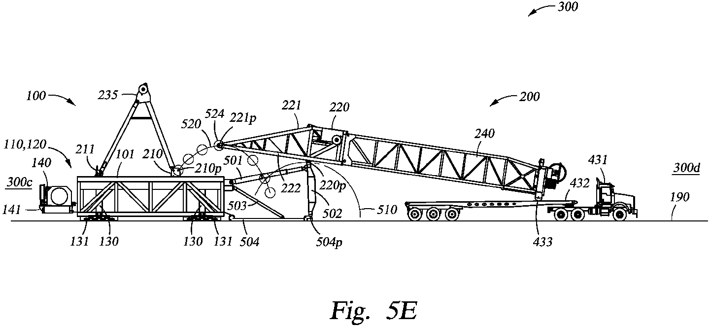
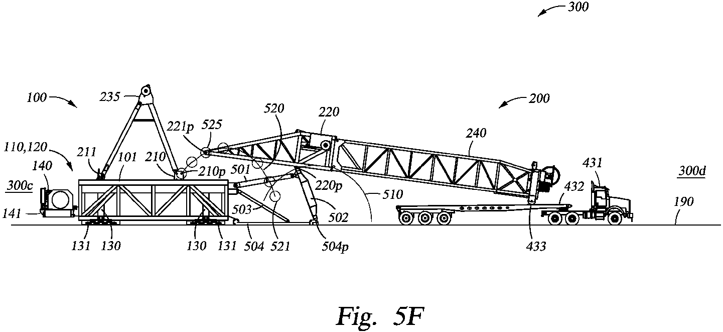
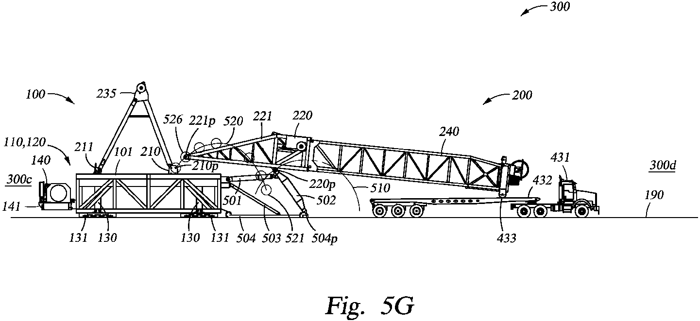

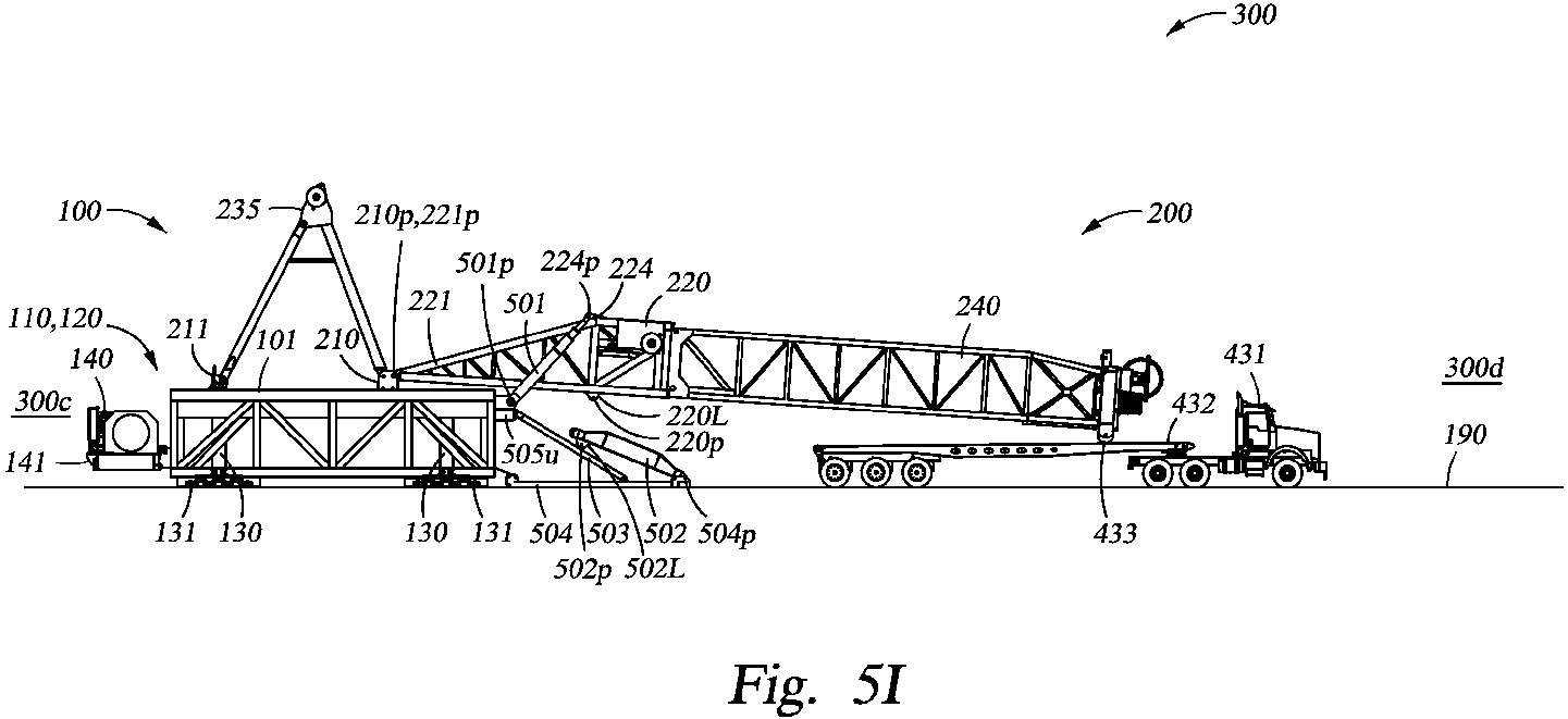
Description
- The present subject matter is generally directed to mobile drilling rig assemblies, and in particular, to a substructure of a mobile drilling rig having telescoping substructure boxes to facilitate drilling rig assembly and erection.
- In many land-based oil and gas drilling operations, drilling rigs are delivered to an oilfield drilling site by transporting the various components of the drilling rig over roads and/or highways. Typically, the various drilling rig components are transported to a drilling site on one or more truck/trailer combinations, the number of which may depend on the size, weight, and complexity of the rig. Once at the drilling site, the drilling rig components are then assembled, and the drilling rig assembly is raised to an operating position so as to perform drilling operations. After the completion of drilling operations, the mobile drilling rig is then lowered, disassembled, loaded back onto truck/trailer combinations, and transported to a different oilfield drilling site for new drilling operations. Accordingly, the ease with which the various drilling rig components can be transported, assembled and disassembled, and raised and lowered can be a substantial factor in the drilling rig design, as well as the rig's overall operational capabilities and cost effectiveness.
- As drilling rig technologies have progressed, the size and weight of mobile drilling rigs has significantly increased so as to meet the higher drilling load capabilities that are oftentimes required to drill deeper wells, particularly in more mature oilfield formations. For example, it is not uncommon for many land-based mobile drilling rigs to have a 1500-2000 HP capability, with hook load capacities of 1 million pounds or greater. Additionally, there are some even larger 3000 HP mobile drilling rigs in operation, with hook and/or rotary load capacities exceeding 1.5 million pounds.
- However, as the capacity - and the overall size and weight - of mobile drilling rigs increases, the size and weight of many of the various components of the rig also proportionately increase, a situation that can sometimes contribute to an overall reduction in at least some of the "mobility" characteristics of the rig. For example, a typical drawworks for a 2000 HP mobile rig may weigh in the range of 80-100 thousand pounds, or even more. Furthermore, individual sections of a drilling rig mast may be 30-40 feet or more in length, and may weigh 20-80 thousand pounds each. In many cases, such large and heavy components require the use of a suitably sized crane so as to lift and position the various drilling components during rig assembly. Accordingly, while each of the various larger rig components may be "transportable" over roads and/or highways from one oilfield drilling site to another, the overall logistical considerations for using at least some higher capacity mobile drilling rigs, e.g., 1500 HP and greater, may need to include having a crane present at a given drilling site prior to the commencement of drilling operations in order to facilitate initial rig assembly. Furthermore, a crane may also need to be present after the completion of drilling operations so as to facilitate rig disassembly for transportation to other oilfield drilling sites. As may be appreciated, the requirement that a crane be used during these assembly/disassembly stages can have a significant impact on the overall cost of the drilling operation, as well as the amount of time that may be needed to perform the operations.
- In some applications, drilling operations at a given oilfield drilling site may involve drilling a plurality of relatively closely spaced wellbores, sometimes referred to as "pad" drilling. In pad drilling, the distance between adjacent wellbores may be as little as 20-30 feet, or even less, and are oftentimes arranged in a two-dimensional grid pattern, such that rows and columns of wellbores are disposed along lines that run substantially parallel to an x-axis and a y-axis, respectively. In such pad drilling applications, after drilling operations have been completed at one wellbore, it is necessary to move the drilling rig to an adjacent wellbore, which can be quite costly and time consuming when a crane is required to disassemble, lift, and move the various drilling rig components to the next wellbore location before drilling operations can commence. Furthermore, even when the fully assembled and erected drilling rig is designed to be moved from wellbore to wellbore via wheeled trailers or dollies, such moving devices are generally only capable of being moved substantially along a single axis, e.g., along an x-axis or along a y-axis. Accordingly, while it may be feasible to trailer such a mobile drilling rig in an axial direction between closely-spaced adjacent wellbores that are disposed along the same column or row of wellbores making up the grid pattern at a given pad drilling site, it is generally not possible to move the mobile drilling rig laterally or longitudinally, e.g., from row to row or from column to column, when using conventional wheeled trailers or dollies.
- Accordingly, there is a need to develop and implement new designs and methods for facilitating the assembly of modern mobile drilling rigs having higher operating capacities without relying on the use of a crane to facilitate the assembly and/or disassembly the rig. Furthermore, there is also a need to facilitate the movement of fully assembled and erected mobile drilling rigs between closely-spaced adjacent wellbores during pad drilling operations. The following disclosure is directed to the design and use of mobile drilling rigs that address, or at least mitigate, at least some of the problems outlined above.
- The following presents a simplified summary of the present disclosure in order to provide a basic understanding of some aspects disclosed herein. This summary is not an exhaustive overview of the disclosure, nor is it intended to identify key or critical elements of the subject matter disclosed here. Its sole purpose is to present some concepts in a simplified form as a prelude to the more detailed description that is discussed later.
- Generally, the subject matter disclosed herein relates to various aspects of a telescoping substructure of a mobile drilling rig that can be collapsed for transportation over highways and/or roads to an oilfield drilling site, and which can also be telescoped, i.e., raised or lowered, as necessary to facilitate assembly of the mobile drilling rig without the use of traditional stand-alone cranes. Furthermore, the telescoping substructure of the present disclosure may be used in conjunction with a mast positioning apparatus during rig assembly to facilitate the positioning of a drilling rig mast above the drilling floor of the mobile drilling rig, and the proper alignment of the drilling rig mast connections with the mast support shoes on the telescoping substructure without the use of a crane. Moreover, substructure raising means and rig moving means may be used to facilitate skid movement of the fully assembled and erected mobile drilling rig between adjacent wellbore locations during pad drilling operations, thereby avoiding the use of heavy lift cranes for disassembly of the rig prior to rig movement.
- In one exemplary embodiment, a telescoping substructure of a drilling rig is disclosed that includes first and second telescoping substructure boxes. The first and second telescoping substructure boxes each include, among other things, a lower substructure box and an upper substructure box that is adapted to be telescopically raised and lowered relative to the lower substructure box. Furthermore, each telescoping substructure box also includes raising means for telescopically raising and lowering the upper substructure box relative to the lower substructure box between a collapsed configuration for transportation and a raised configuration for drilling operations, wherein each of the first and second telescoping substructure boxes are adapted to facilitate movement of the telescoping substructure in at least one of a lateral direction and a longitudinal direction over wellhead equipment positioned above a wellbore location when the upper substructure boxes are in the raised configuration.
- Also disclosed herein is an illustrative method that includes, among other things, positioning a first telescoping substructure box adjacent to and laterally spaced apart from a second telescoping substructure box, the first and second telescoping substructure boxes each having an upper substructure box, a lower substructure box, and raising means for telescopically raising and lowering the respective first and second telescoping substructure boxes. The disclosed method further includes telescopically raising the laterally spaced apart first and second telescoping substructure boxes to a raised configuration for drilling operations by telescopically raising, with the raising means, the upper substructure boxes relative to the respective lower substructure boxes, and performing drilling operations with a drilling rig comprising the first and second telescoping substructure boxes on a first wellbore location positioned between the laterally spaced apart first and second telescoping substructure boxes. Additionally, the disclosed method also includes moving the drilling rig from the first wellbore location to a second wellbore location while the first and second telescoping substructure boxes are in the raised configuration and while pressure-retaining equipment is positioned above at least one of the first and second wellbore locations.
- In another illustrative embodiment, a drilling rig mast erection system is disclosed that includes, among other things, a mast support shoe fixedly attached to a drilling rig substructure, the mast support shoe having a first pinned connection. Furthermore, the drilling rig mast erection system also includes a bottom mast section of a drilling rig mast, the bottom mast section having a second pinned connection that is adapted to be pivotably connected to the first pinned connection of the mast support shoe. Moreover, the disclosed mast erection system includes a mast positioning apparatus that is adapted to pivotably position the bottom mast section so that the second pinned connection of the bottom mast section is positioned adjacent to the first pinned connection of the mast support shoe.
- Yet another exemplary embodiment of the present disclosure is a method for erecting a drilling rig mast that includes, among other things, pivotably connecting a first end of bottom mast support spreader to a bottom mast section of the drilling rig mast and pivotably rotating the bottom mast support spreader about a second end of the bottom mast support spreader to pivotably position a first pinned connection of the bottom mast section adjacent to a second pinned connection of a mast support shoe. The disclosed method further includes pivotably connecting the first pinned connection of the bottom mast section to the second pinned connection of the mast support shoe.
- The disclosure may be understood by reference to the following description taken in conjunction with the accompanying drawings, in which like reference numerals identify like elements, and in which:
-
Figures 1A and1B are side and end elevation views, respectively, of a mobile drilling rig having a telescoping substructure in accordance with one illustrative embodiment of the present disclosure; -
Figure 1C is a plan view of the illustrative telescoping substructure ofFigs. 1A and1 B; -
Figures 2A-2C are end elevation, side elevation, and plan views, respectively, of one illustrative embodiment of an upper telescoping substructure box disclosed herein; -
Figures 2D-2F are end elevation, side elevation, and plan views, respectively, of an illustrative lower telescoping substructure box according to the present disclosure; -
Figures 2G and 2H are end and side elevation views, respectively, of the upper and lower telescoping substructure boxes ofFigs. 2A-2D in an assembled and collapsed configuration; -
Figures 2I and 2J are end and side elevation views, respectively, of the upper and lower telescoping substructure boxes ofFigs. 2A-2D in an assembled and raised configuration; -
Figures 3A-3C are side elevation views of an early stage of assembling an illustrative mobile drilling rig disclosed herein, wherein a truck/trailering package is used to transport and position an illustrative telescoping substructure box in preparation for further rig assembly stages; -
Figure 4A is a side elevation view of one embodiment of a mobile drilling rig disclosed herein during a rig assembly stage wherein a substructure center floor section is being positioned by a truck/trailer combination adjacent to illustrative telescoping substructure boxes of the present disclosure; -
Figure 4B is an end elevation view of the substructure center floor section and trailer ofFig. 4A being positioned between illustrative driller's side and off-driller's side telescoping substructure boxes; -
Figure 4C is an end elevation view of the illustrative embodiment depicted inFig. 4B during a further rig assembly stage, wherein the substructure center floor section is being lifted off of the trailer by raising the illustrative driller's side and off-driller's side upper telescoping substructure boxes; -
Figure 5A is a side elevation view of an illustrative mobile drilling rig of the present disclosure during a later rig assembly stage, wherein a mast positioning apparatus has been attached to an illustrative telescoping substructure and a bottom mast section of a drilling rig mast has been pivotably attached to the mast positioning apparatus; -
Figure 5B shows an exemplary embodiment of the mobile drilling rig ofFig. 5A during a subsequent stage of rig assembly, wherein an upper mast section of the drilling rig mast has been attached to the bottom mast section; -
Figures 5C-5H show various sequential rig assembly stages of the illustrative mobile drilling rig depicted inFig.5B , wherein the mast positioning apparatus is being used to move the lower end of the bottom mast section into position adjacent to mast support shoes on the telescoping substructure; -
Figure 5I depicts the mobile drilling rig ofFigs. 5B-5H in a further illustrative rig assembly stage, wherein the drilling rig mast has been pivotably attached to the mast support shoes and the mast raising apparatus has been pivotably attached to the drilling rig mast; -
Figure 5J shows the illustrative mobile drilling rig ofFig. 5I in yet a further stage of rig assembly, wherein the drilling rig mast has been lifted off of a truck/trailer combination and temporarily supported on a mast support stand; -
Figure 6A is a side elevation view of one illustrative embodiment of a mobile drilling rig disclosed herein after the drilling rig mast has been raised to a substantially vertical orientation; -
Figures 6B and6C are side and end elevation views, respectively, of the mobile drilling rig ofFig. 6A after an illustrative telescoping substructure of the present disclosure has been used to raise the mobile drilling rig to an operating height; -
Figures 7A and7B are side and end elevation views, respectively, of an exemplary mobile drilling rig of the present disclosure, wherein illustrative substructure raising apparatuses have been used to lift the mobile drilling rig in preparation for moving the rig to an adjacent wellbore location; and -
Figures 7C-7H are close-up side elevation views showing various sequential steps wherein the exemplary mobile drilling rig ofFig. 7A is moved to an adjacent wellbore location. - While the subject matter disclosed herein is susceptible to various modifications and alternative forms, specific embodiments thereof have been shown by way of example in the drawings and are herein described in detail. It should be understood, however, that the description herein of specific embodiments is not intended to limit the invention to the particular forms disclosed, but on the contrary, the intention is to cover all modifications, equivalents, and alternatives falling within the spirit and scope of the invention as defined by the appended claims.
- Various illustrative embodiments of the present subject matter are described below. In the interest of clarity, not all features of an actual implementation are described in this specification. It will of course be appreciated that in the development of any such actual embodiment, numerous implementation-specific decisions must be made to achieve the developers' specific goals, such as compliance with system-related and business-related constraints, which will vary from one implementation to another. Moreover, it will be appreciated that such a development effort might be complex and time-consuming, but would nevertheless be a routine undertaking for those of ordinary skill in the art having the benefit of this disclosure.
- The present subject matter will now be described with reference to the attached figures. Various systems, structures and devices are schematically depicted in the drawings for purposes of explanation only and so as to not obscure the present disclosure with details that are well known to those skilled in the art. Nevertheless, the attached drawings are included to describe and explain illustrative examples of the present disclosure. The words and phrases used herein should be understood and interpreted to have a meaning consistent with the understanding of those words and phrases by those skilled in the relevant art. No special definition of a term or phrase, i.e., a definition that is different from the ordinary and customary meaning as understood by those skilled in the art, is intended to be implied by consistent usage of the term or phrase herein. To the extent that a term or phrase is intended to have a special meaning, i.e., a meaning other than that understood by skilled artisans, such a special definition will be expressly set forth in the specification in a definitional manner that directly and unequivocally provides the special definition for the term or phrase. Generally, the subject matter disclosed herein is directed to mobile drilling rig assemblies having telescoping substructure boxes, which may be used to facilitate the assembly and installation of large and/or heavy drilling rig components, such as a drilling rig mast, rig drawworks, driller's cabin, and the like, without relying on the use of a stand-alone crane to lift and/or position the various rig components. Furthermore, a mast positioning apparatus is disclosed herein that may be used to position the drilling rig mast adjacent to the mast support shoes on the drilling floor while the telescoping substructure boxes are in a collapsed configuration, thereby allowing the mast to be pivotably attached to mast support shoes in preparation for mast erection. Also disclosed are substructure raising apparatuses that may be used to telescope, i.e., raise and lower, the telescoping substructure boxes during drilling rig assembly, as well as lift the assembled mobile drilling rig for skid movement between adjacent wellbore locations during pad drilling operations.
-
Figures 1A and1B are side and end elevation views, respectively, of an illustrativemobile drilling rig 300 accordingly to the present disclosure that generally includes a driller'sside 300a, an off-driller'sside 300b, adrawworks side 300c, and asetback side 300d. More specifically,Fig. 1A is an elevation view of therig 300 when viewed from the driller'sside 300a of therig 300, andFig. 1B is an elevation view of therig 300 when viewed from thesetback side 300d, or front side, of therig 300. As shown in the illustrative embodiment depicted inFigs. 1A and1B , themobile drilling rig 300 may include, among other things, atelescoping substructure 100 and adrilling rig mast 200. In certain illustrative embodiments, thetelescoping substructure 100 may include a driller'sside 300atelescoping substructure box 110 that is made up of anupper substructure box 110u and alower substructure box 110L, an off-driller'sside 300btelescoping substructure box 120 that also includes upper andlower substructure boxes center floor section 125 positioned between and supported by theupper substructure boxes upper substructure box lower substructure box upper substructure boxes lower substructure boxes telescoping substructure boxes telescoping substructure 100, e.g., the upper surfaces of thetelescoping substructure boxes center floor section 125 may form adrilling floor 101 where personnel, as well as materials and equipment, may be present during the various drilling rig operations. - As shown in
Figs. 1A and1B , a drillingrig cellar area 150 is located between thetelescoping substructure boxes center floor section 125. Pressure-retainingwellhead equipment 160, such as a blowout preventer apparatus and the like, may be positioned in thecellar area 150 above awellbore location 170, where drilling operations may be performed so as to drill and advance a wellbore below the surface of theground 190. Furthermore, when themobile drilling rig 300 is utilized at an oilfield drilling site where pad drilling operations are performed, additional wellbore locations may be located closely adjacent to thewellbore location 170. For example, a driller'sside 300a wellbore location 171 and an off-driller'sside 300b wellbore location 172 may be laterally positioned on either side of thewellbore location 170, as shown inFig. 1B . Similarly, adrawworks side 300c wellborelocation 173 and asetback side 300d wellbore location 174 may be longitudinally positioned on either side of thewellbore location 170, as shown inFig. 1A Depending on the specific grid pattern layout of the wellbore locations for the pad drilling site in question, each of the wellbore locations 171-174 may be located atrespective distances 171d-174d away from thewellbore location 170, which may be as close as approximately 20 feet or less, or as far away as approximately 100 feet or more. It should be appreciated, however, that other spacing distances may also be used in pad drilling applications. Moreover, it should also be appreciated that the spacing between thewellbore location 170 and each of the adjacent wellbore locations 171-174 need not be uniform, e.g., each of thedistances 171 d-174d may be different. - In at least some exemplary embodiments of the present disclosure, a
drawworks 140 may be attached to theupper substructure boxes telescoping substructure 100, as shown inFig. 1A . For example, thedrawworks 140 may be supported by adrawworks skid 141, which may include appropriately designedconnections 141 p that are adapted to removably attach thedrawworks skid 141 and drawworks 140 to supportclips 142 on each of theupper substructure boxes - In certain embodiments, a driller's
side 300aancillary structure 119 may be removably attached to the driller'sside 300atelescoping substructure box 110 as shown inFig. 1B , which may include, for example, a driller'scabin 119a, andcontrol cabin 119b, and the like. In other embodiments, an off-driller'sside 300bancillary structure 129 may also be removably attached to the off-driller'sside 300btelescoping substructure box 120, which may include, among other things, awind wall 129a,standpipe manifold 129b, and the like. It should be understood, however, that the various components of the driller'sside 300a and off-driller'sside 300bancillary structures mobile drilling rig 300, or thedrilling rig 300 may be used without any such ancillary structures. - As shown in the illustrative embodiment depicted in
Figs. 1A and1B , thetelescoping substructure 100 may also include means for telescopically raising raise and/or lowering theupper substructure boxes 110u and/or 120u relative to a respectivelower substructure box 110L and/or 120L - i.e., means for "telescoping" thesubstructure boxes mobile drilling rig 300, thesubstructure raising apparatuses 130 may be adapted to telescopically raise and lower thesubstructure boxes substructure raising apparatuses 130 may be adapted to generate a force of sufficient magnitude to raise theupper substructure boxes lower substructure boxes mobile drilling rig 300 is in a fully assembled condition, e.g., including all equipment and structures such as thedrilling rig mast 200,drawworks 140,ancillary structures 119 and/or 129, etc. Furthermore, in at least some embodiments, the means for raising and lowering thetelescoping substructure boxes substructure boxes ground 190, and/or lifting and lowering the fully assembledmobile drilling rig 300 relative to theground 190, depending on the specific rig assembly, operating, or disassembly stage. - For example, the means for raising and lowering the
telescoping substructure boxes substructure raising apparatuses 130 shown inFigs. 1A and1B , may be used to lift and/or lower thetelescoping substructure boxes ground 190 during an unloading stage after the fully collapsedsubstructure boxes Figs. 3A-3C below, and/or to re-load the fully collapsedsubstructure boxes telescoping substructure 100 may also be appropriately sized so that the means can be used for lifting and lowering the fully assembledmobile drilling rig 300 relative to theground 190 so that therig 300 can be skidded from, for example, thewellbore location 170 to an adjacent wellbore location 171-174, as will also be further discussed with respect toFigs. 7A and7B below. - In at least some embodiments, each of the
substructure raising apparatuses 130 may be, for example, a telescoping hydraulic and/or pneumatic cylinders, screw and/or gear mechanisms, chain and sprocket arrangements, or cable and pulley/roller arrangements and the like. See, for example, thesubstructure raising apparatuses 130 shown inFigs. 1A and1B . Furthermore, each substructure raising apparatus 130 (or apparatuses 130) may be attached at an upper end thereof to an appropriately designed structural support member 114 (or members 114) on the respectiveupper substructure boxes substructure raising apparatuses 130 may also have attached at a lower end thereof a respective bearing plate orskid foot 131, which is typically used to transfer the weight of thetelescoping substructure 100, or the fully assembledmobile drilling rig 300, to theground 190 during substructure telescoping (raising and/or lowering) operations. Additionally, in those illustrative embodiments of themobile drilling rig 300 that are adapted to perform pad drilling operations, means for moving the fully assembledrig 300 may be operatively coupled to thetelescoping substructure 100. For example, in at least some exemplary embodiments, the means for moving the fully assembled mobile drilling rig may include a skidfoot movement apparatus 132 that may be positioned between and operatively coupled to eachsubstructure raising apparatus 130 and itsrespective skid foot 131 so as to facilitate skid movement of the fully assembledrig 300 between adjacentwellbore locations 170 and 171-174, as will be further described with respect toFigs. 7C-7H below. -
Figure 1C is a plan view of theillustrative telescoping substructure 100 taken along the view line "1C-1 C" ofFig. 1B , wherein some elements of themobile drilling rig 300, such as thedrilling rig mast 200 anddrilling floor 101 above each of thetelescoping substructure boxes substructure raising apparatuses 130 may be positioned near a respective corner of thetelescoping substructure 100, i.e., such that onesubstructure raising apparatus 130 is proximate eachend telescoping substructure boxes substructure raising apparatuses 130 may be substantially centered below a respectivestructural support member 114, as shown inFig. 1C . Accordingly, eachtelescoping substructure box substructure raising apparatuses 130 located at therespective ends - As noted above, in the exemplary
mobile drilling rig 300 illustrated inFigs. 1A-1C , a singlesubstructure raising apparatus 130 is positioned near each corner of thetelescoping substructure 100. However, it should be appreciated that, in light of the general concepts described above, more than onesubstructure raising apparatus 130 may be used at each respective corner location. For example, in certain embodiments, it is well within the scope of the present disclosure to utilize a plurality ofsubstructure raising apparatuses 130, e.g., two, three, four or even more raisingapparatuses 130, near each corner of thetelescoping substructure 100. Furthermore, whileFig. 1C illustrates only onestructural support member 114 near each corner of thetelescoping substructure 100, it should be understood that a plurality ofstructural support members 114 may be used at each corner location, depending on the specific design and/or quantity of raisingapparatuses 130 utilized. For example, in those illustrative embodiments wherein a plurality of raisingapparatuses 130, e.g.,, two or more, are used at each corner location, two or morestructural support members 114 may also be used. Furthermore, when two or morestructural support members 114 are used, they may be arranged in any appropriate or suitable configuration, such as parallel spaced apart members or cross members and the like, depending on the specific rig design considerations such as the number of raisingapparatuses 130, the anticipated lift and/or operating loads for themobile drilling rig 300, etc. - Also as shown in
Figs. 1A and1B , themobile drilling rig 300 may include adrilling rig mast 200 positioned above thetelescoping substructure 100 and thedrilling floor 101. In certain embodiments, thedrilling rig mast 200 may include abottom mast section 220 and anupper mast section 240. Depending on the specific mast design parameters, thedrilling rig mast 200 may be pivotably attached to and supported bymast support shoes 210, which may be fixedly attached, e.g., bolted, to theupper substructure boxes drilling rig mast 200 may also be removably attached to and further supported by anA-frame structure 235, as shown inFig. 1A . In at least some embodiments, the front legs of theA-frame structure 235 may be removably attached to and supported by the mast support shoes 210 (see,Fig. 1A ), and the rear legs of theA-frame structure 235 may be removably attached to and supported by respective leg support shoes 211, which may also be fixedly attached to theupper substructure boxes - It should be appreciate by a person of ordinary skill in the art after a full reading of the subject matter disclosed herein that the configuration of the
drilling rig mast 200 shown inFigs. 1A and1B and described above is exemplary only, and that other mast design configurations may also be used that are within the spirit and scope of the present disclosure. -
Figures 2A-2J depict various aspects of an illustrativetelescoping substructure box 110, such as the driller'sside 300atelescoping substructure box 110 shown inFigs. 1A-1C . It should be understood, however, that while the details described with respect toFigs. 2A-2J are specific to the driller'sside 300atelescoping substructure box 110, the following description is also generally applicable to the respective details of an off-driller'sside 300btelescoping substructure box 120. -
Figures 2A, 2B, and 2C are end elevation, side elevation, and plan views, respectively, of an illustrativeupper substructure box 110u. As shown inFigs. 2B and 2C , theupper substructure box 110u may include upper horizontalstructural members 111h and lower horizontalstructural member 112h running along either side of theupper substructure box 110u. In some embodiments, the upper horizontalstructural members 111h may be separated from the lower horizontalstructural members 112h by a plurality of verticalstructural members 113v and a plurality ofcross members 113c, as shown inFig. 2B . Furthermore, theupper substructure box 110 may include an appropriately designedstructural support member 114, or a plurality ofstructural support members 114 as descried above, which may be fixedly attached, e.g., welded or bolted, at each end thereof to a respective horizontalstructural member 111 h. In some embodiments, eachstructural support member 114 may be appropriately positioned and adapted to transfer loads from thetelescoping substructure 100, or the fully assembledmobile drilling rig 300, to a respectivesubstructure raising apparatus 130, as previously described. - Additionally, as shown in
Fig. 2A , the respective upper horizontalstructural members 111 h on opposite sides of theupper substructure box 110u may be separated by upperhorizontal end members 111 e and one or more upperhorizontal cross members 111 c extending therebetween, which may be used to stabilize the upper horizontalstructural members 111h and support the drilling floor 101 (see,Figs. 1A and1B ). Together, thestructural members upper frame 111. Furthermore, the respective lower horizontalstructural members 112h may be separated by lowerhorizontal end members 112e. Additionally, anend cross member 113e may also run across each end of theupper substructure box 110u between the upper and lowerhorizontal end members structural members 113v located at each end of theupper substructure box 110u. - In certain exemplary embodiments, unlike the upper
horizontal cross members 111c andstructural support members 114 extending between the opposing upper horizontalstructural members 111 h, there may be no cross members other than theend members 112e extending between the opposing lower horizontalstructural members 112h. Accordingly, it should be understood that the lower horizontalstructural members 112h and the lowerhorizontal end members 112e extending therebetween may define a substantially "open"bottom frame 112 having an inside end-to-end length 112L and an inside side-to-side width 112w. Furthermore, theinside length 112L and insidewidth 112w of thebottom frame 112 may be sized so as to allow the insertion of thelower substructure box 110L therethrough. Additionally, in at least some embodiments, the plurality of variousstructural members upper substructure box 110u may be arranged so as to define a substantially "open"interior space 110p. Moreover, the substantially "open"interior space 110p may be sized to receive at least a portion of thelower substructure box 110L after it is inserted through the substantially "open"bottom frame 112, thereby facilitating at least a partial "nesting" of thelower substructure box 110L within theupper substructure box 110u, and a consequent "telescoping" operation of thetelescoping substructure box 110, as will be further described with respect toFigs. 2G-2J below. -
Figures 2D, 2E, and 2F are end elevation, side elevation, and plan views, respectively, of an illustrativelower substructure box 110L. As shown inFigs. 2E and 2F , thelower substructure box 110L may include upper horizontalstructural members 115h running along either side of thelower substructure box 110L. As shown inFig. 2F , the respective upper horizontalstructural members 115h on opposite sides of thelower substructure box 110L may be separated by upperhorizontal end members 115e and one or more upperhorizontal cross members 115c, thus defining anupper frame 115 having an outside end-to-end length 115L and an outside side-to-side width 115w. In certain illustrative embodiments, thelower substructure box 110L may include abase support box 118 at each end thereof, each of which may include lower horizontalstructural members 116h running along either side of thelower substructure box 110L. Additionally, the lower horizontalstructural members 116h of each base support box may be separated from the upper horizontalstructural members 115h by a plurality of verticalstructural members 117v and a plurality ofcross members 117c. Furthermore, the respective lower horizontalstructural members 116h may be separated by lowerhorizontal end members 116e located on either end of eachbase support box 118. In some embodiments, an end cross member 117e may also run across each end of thelower substructure box 110L between the upper and lowerhorizontal end members structural members 117v located at each end of thelower substructure box 110L. - It should be appreciated by those of ordinary skill that the specific structural configurations of the upper and
lower substructure boxes Figs. 2A-2F and described above are exemplary only, and that other design configurations may also be used that generally fall with in the spirit and scope of the present disclosure. - In at least some illustrative embodiments of the
telescoping substructure box 110 disclosed herein, the upper andlower substructure boxes lower substructure box 110L fits inside of theupper substructure box 110u. More specifically, as noted above, the size of thelower substructure box 110L, i.e., the size of theupper frame 115, may be adapted so that thelower substructure box 110L may be inserted through the substantially "open"bottom frame 112 and at least partially "nested" within the substantially "open"interior space 110p of theupper substructure box 110u, thereby facilitating a sliding engagement, or "telescoping" action, between the twosubstructure boxes end length 115L of thelower substructure box 110L (i.e., outside of the upperhorizontal end members 115e, as shown inFig. 2F ) may be adjusted so that it is less than the inside end-to-end length 112L (i.e., inside of the lowerhorizontal end members 112e, as shown inFig. 2B ) of theupper substructure box 110u. Similarly, the outside side-to-side width 115w of thelower substructure box 110L (i.e., outside of the upper horizontalstructural members 115h, as shown inFig. 2F ) may also be adjusted so that it is less than the inside side-to-side width 112w (i.e., inside of the lower horizontalstructural members 112h, as shown inFig. 2A ) of theupper substructure box 110u. Furthermore, in certain embodiments, one or both of thesubstructure boxes substructure boxes telescoping substructure box 110 is being raised or lowered. -
Figures 2G and 2H are end and side elevation views, respectively, of the driller'sside 300atelescoping substructure box 110 in a fully collapsed configuration, wherein thesubstructure raising apparatuses 130,skid feet 131, and skidfoot movement apparatuses 132 are not shown for clarity. As shown inFigs. 2G and 2H , almost the entirety of thelower substructure box 110L may be inserted into theupper substructure box 110u from below, and the twosubstructure boxes upper frame 115 on thelower substructure box 110L is positioned adjacent to theupper frame 111 on theupper substructure box 110u. Furthermore, anupper surface 115s of theupper frame 115 on thelower substructure box 110L may also be positioned adjacent to, or even substantially in contact with, thestructural support members 114 and/or the upperhorizontal cross members 111c of theupper frame 111 on theupper substructure box 110u. In this configuration, thetelescoping substructure box 110 is in a substantially fully collapsed configuration, and has a fully collapsed or loweredheight 100L that, in some embodiments, may be approximately 10-12 feet, whereas in other embodiments, the loweredheight 100L may be in the range of approximately 15-18 feet. However, it should be appreciated by those having ordinary skill in the art after having the full benefit of the subject matter disclosed herein that the loweredheight 100L may be adjusted as necessary depending on the specific rig design and overall substructure height requirements during rig operations. -
Figures 2I and 2J are end and side elevation views, respectively, of the driller'sside 300atelescoping substructure box 110 in a fully raised configuration, wherein thesubstructure raising apparatuses 130,skid feet 131, and skidfoot movement apparatuses 132 are again not shown for clarity. As shown inFigs. 2I and 2J , theupper substructure box 110u may be telescoped up relative to thelower substructure box 110L until theupper frame 112 on theupper substructure box 110u is positioned adjacent to theupper frame 115 on thelower substructure box 110u. Furthermore, anupper surface 112s of theupper frame 112 on theupper substructure box 110u may also be positioned adjacent to, or even substantially aligned, with theupper surface 115s of theupper frame 115 on thelower substructure box 110L, as shown inFig. 2J . In this configuration, thetelescoping substructure box 110 is in a substantially fully raised - or "telescoped" - configuration. Furthermore, in at some exemplary embodiments, when thetelescoping substructure box 110 is in the fully raised or "telescoped" configuration ofFig. 2J , it has a fully raisedheight 100h which may range from approximately 20-30 feet or even greater, depending on the overall design considerations of themobile drilling rig 300. Furthermore, in the fully raised configuration, thetelescoping substructure box 110 may also provide a side-to-side open space below theupper frame 115 and between thebase support boxes 118 that substantially defines aside clearance 151. In some embodiments, theside clearance 151 may range from approximately 7-10 feet, while in other embodiments theside clearance 151 may be approximately 12-15 feet. - It should be understood that the particular configurations and relative arrangements of the upper and
lower substructure box lower substructure boxes Figs. 2A-2J are illustrative only, and that other configurations and relative arrangements may also be used. For example,Figs. 2A-2J illustrate a configuration and arrangement of the driller'sside 300atelescoping substructure box 110 wherein thelower substructure box 110L is at least partially inserted into, or "nested" within, the substantially "open"interior space 110p of theupper substructure box 110u. It should be appreciated by those of ordinary skill after a full and complete reading of the present disclosure that thetelescoping substructure box 110 may be configured and arranged such that theupper substructure box 110u is at least partially inserted into, or "nested" within, a corresponding "open" interior space of thelower substructure box 110L substantially without affecting the function and/or operation of thetelescoping substructure box 110 or thetelescoping substructure 100. -
Figures 3A-3C are side elevation views of an illustrativetelescoping substructure box 110 that is being transported and positioned on theground 190 as a preliminary step in assembling themobile drilling rig 300 illustrated inFigs. 1A and1B . While the details shown inFigs. 3A-3C and described below are specifically directed to transporting and positioning the driller'sside 300atelescoping substructure box 110, it should be understood that these details are also generally applicable to the off-driller'sside 300btelescoping substructure box 120. -
Figure 3A depicts an illustrative driller'sside 300atelescoping substructure box 110 that is being transported over theground 190 by atruck 401. In some illustrative embodiments, agooseneck 402 may be removably attached to one end of thetelescoping substructure box 110, and awheeled trailering package 403 may be removably attached to the opposite end of thetelescoping substructure box 110. Thegooseneck 402 may then be removably connected to a fifth wheel connection on thetruck 401 so as to facilitate transportation of thetelescoping substructure box 110 over highways and/or roads from one oilfield drilling site to another, as well as over theground 190 at a given oilfield drilling site. - As shown in
Fig. 3A , thetelescoping substructure box 110 is typically transported over theground 190 in a fully collapsed configuration, such that aclearance 110c is maintained between theground 190 and the bottom of eachskid foot 131. In certain illustrative embodiments, theclearance 110c is maintained during transportation of thetelescoping substructure box 110 by temporarily attaching thelower substructure box 110L to theupper substructure box 110u, such as by the use of removable shear pins, bolts, clamps and the like (not shown). Furthermore, in at least some embodiments disclosed herein, when thewheeled trailering package 403 is attached and thetelescoping substructure box 110 is being trailered by thetruck 401 during road or highway transportation, aheight 110h of thebox 110 may be adapted so as to substantially comply with at least some height restrictions that may typically be imposed during such road and/or highway transportation. -
Figure 3B shows thetelescoping substructure box 110 after it has been transported to a given oilfield drilling site and appropriately positioned proximate a wellbore location 170 (see, e.g., thewellbore location 170 shown inFigs. 1A and1B ). In certain embodiments, thesubstructure raising apparatuses 130 shown inFig. 3B may be actuated, i.e., extended, so as to lower theskid feet 131 relative to the upper andlower substructure boxes ground 190. Once the load of thetelescoping substructure box 110 is supported by thesubstructure raising apparatuses 130 andskid feet 131, theremovable gooseneck 402 and removablewheeled trailering package 403 may then be detached from thelower substructure box 110L and moved away as required. Next, in some embodiments, the substructure raising apparatuses may again be actuated, i.e., retracted, so as to lower thetelescoping substructure 110 until thebase support boxes 118 of thelower substructure box 110L are also in bearing contact with theground 190, as shown inFig. 3C . Thereafter, the devices used to temporarily attach thelower substructure box 110L to theupper substructure box 110u, e.g., pins, bolts, clamps, etc. (not shown), may be removed in preparation for telescoping thesubstructure box 110 during subsequent drill rig assembly activities, as will be further described with respect toFigs. 4A-4C and5A-5J below. - As noted previously, the above-described steps are typically performed after the
telescoping substructure box 100 has been appropriately positioned proximate a specific wellbore location, such as thewellbore location 170. In some embodiments, thetruck 401 may be used to trailer thetelescoping substructure box 110 to a specified final location, after which thesubstructure raising apparatuses 130, i.e., means for "telescoping" thesubstructure box 110, may be used to lower thesubstructure box 110 in the manner described above. In other illustrative embodiments, thetruck 401 may be used to position thetelescoping substructure box 110 adjacent to the specified final location and thesubstructure box 110 lowered to theground 190 as previously, after which thesubstructure box 110 may be skidded, i.e., moved, to the specified final location using the skidfoot movement apparatuses 132 in the manner described with respect toFigs. 7A and7B below. -
Figure 3C shows the illustrative driller'sside 300atelescoping substructure box 110 ofFigs. 3A and 3B after completion of the above-described steps. Furthermore, in at least some embodiments, amast support shoe 210 may be removably attached to theupper substructure box 110u. Depending on the specific drilling rig mast design used for themobile drilling rig 300, themast support shoe 210 may be adapted to pivotably support a drilling rig mast, such as thedrilling rig mast 200 shown inFigs. 1A and1B , by way of an appropriatelysized pin hole 210p. Furthermore, themast support shoe 210 may also include a second suitablysized pin hole 210a, which, in at least some embodiments, may be used to removably attach a front leg of an A-frame structure, such as theA-frame structure 235 ofFigs. 1A and1B , to themast support shoe 210. Additionally, aleg support shoe 211 may also be removably attached to theupper substructure box 110u, which may be used to removably attached a rear leg of the A-frame structure, such as theA-frame structure 235 ofFigs. 1A and1B , to thetelescoping substructure box 110 by way of an appropriatelysized pin hole 211 p. -
Figures 4A-4C illustrate further assembly stages of themobile drilling rig 300 disclosed herein, after the driller'sside 300a and off-driller'sside 300btelescoping substructure boxes wellbore location 170 in the manner previously described with respect toFigs. 3A-3C above. More specifically,Fig. 4A is a side elevation view showing a substructurecenter floor section 125 being positioned adjacent to thetelescoping substructure 100 for installation thereon. As shown in the illustrative embodiment ofFig. 4A , the substructurecenter floor section 125 may be positioned on atrailer 412 that is attached atruck 411, which may be used to move thetrailer 412 over theground 190 and adjacent to thetelescoping substructure 100. In certain embodiments, the substructurecenter floor section 125 may be supported on thetrailer 412 by support stands 413, which may be sized so as to hold the substructurecenter floor section 125 at an appropriate height for installation onto thetelescoping substructure 100, as will be further described below. -
Figure 4B is an end elevation view of one embodiment of thetelescoping substructure 100 disclosed herein, wherein the substructurecenter floor section 125 andtrailer 412 ofFig. 4A have been positioned between the illustrative driller'sside 300a and off-driller'sside 300btelescoping substructure boxes Fig. 4B , thedrilling floor 101 on the substructurecenter floor section 125 may be positioned at a height level that is higher than thecorresponding drilling floor 101 on each of the adjacenttelescoping substructure boxes center floor section 125 as shown inFig. 4C and described below. - In some exemplary embodiments, the
telescoping substructure boxes wellbore location 170 as shown inFig. 4B . Furthermore, thetrailer 412 supporting the substructurecenter floor section 125 may be positioned substantially directly above thewellbore location 170. In at least some exemplary embodiments, thetelescoping substructure boxes side support members Fig. 4B ), which may be appropriately designed to support the substructurecenter floor section 125 by engaging corresponding connections (not shown) on thecenter floor section 125. - In certain embodiments, any or all ancillary structures that may be required for operation of the
mobile drilling rig 300 disclosed herein may also be positioned for attachment to and/or installation on thetelescoping substructure boxes Fig. 4B . For example, in some embodiments, a driller'sside 300aancillary structure 119, which may include a driller'scabin 119a and/or acontrol cabin 119b (see,Fig. 1B ) may be supported by astructural support 119s, which in turn may be removably attached to the driller'sside 300aupper substructure box 110u by way of an appropriately designedconnection 119p. Furthermore, an ancillarystructure raising apparatus 119r, such as a suitably designed scissors apparatus and the like, may be disposed between and attached to theancillary structure 119 and thestructural support 119s. In at least one embodiment, theancillary raising apparatus 119r may be adapted to raise theancillary structure 119 up to the level of thedrilling floor 101 on the driller'sside 300atelescoping substructure box 110. In other embodiments, an off-driller'sside 300bancillary structure 129 may be supported on asecond trailer 422 attached to a second truck (not shown inFig. 4B ) and positioned adjacent to the off-driller'sside 300btelescoping substructure box 120. Theancillary structure 129 may then be pivotably attached to the off-driller'sside 300bupper substructure box 120u by way of a suitably designedpivotable connection 129p. It should be understood, however, that either or both of theancillary structures telescoping substructure boxes -
Figure 4C is an end elevation view of theillustrative telescoping substructure 100 depicted inFig. 4B during a further rig assembly stage, wherein the substructurecenter floor section 125 is being lifted off of thetrailer 412. In some exemplary embodiments, the substructurecenter floor section 125 may be lifted by actuating thesubstructure raising apparatuses 130, thereby telescoping, i.e., raising, both the driller'sside 300a and off-driller'sside 300bupper substructure boxes lower substructure boxes upper substructure boxes side support members center floor section 125, thereby lifting the substructurecenter floor section 125 off of the support stands 413. Furthermore, the respectiveside support members center floor section 125 may be adapted so that, when engaged, the level of thedrilling floor 101 on the substructurecenter floor section 125 is substantially level and aligned with thecorresponding drilling floor 101 on eachtelescoping substructure box - After the substructure
center floor section 125 has been lifted off of thetrailer 412 and is supported by the adjacenttelescoping substructure boxes Fig. 4A ) may be used to move thetrailer 412 away from thetelescoping substructure 100, and thetelescoping substructure 100 may be lowered back down to a fully collapsed configuration with the substructurecenter floor section 125 positioned thereon. Furthermore, it should be appreciated that, in those illustrative embodiments wherein the off-driller'sside 300bancillary structure 129 may have been previously positioned adjacent to the off-driller'sside 300btelescoping substructure box 120 on asecond trailer 422 and pivotably attached thereto as shown inFig. 4B , theancillary structure 129 will also be lifted off of thesecond trailer 422 when thesubstructure raising apparatuses 130 are actuated so as to "telescope" thetelescoping substructure 100. Accordingly, thesecond trailer 422 may also be moved away from thetelescoping substructure 100 prior to lowering thetelescoping substructure 100 down to the fully collapsed configuration. - In some illustrative embodiments, the driller's
side 300aancillary structure 119 may also be moved into position on a trailer (not shown) in a substantially similar fashion to that shown inFigs. 4B and 4C for the off-driller'sside 300bancillary structure 129. Moreover, thedrawworks skid 141 with thedrawworks 140 thereon (not shown inFigs. 4A-4C ; see, e.g.,Fig. 1A , described above) may also be positioned adjacent to thedrawworks side 300c of thetelescoping substructure 100 in a similar manner, then attached to theupper substructure boxes ancillary structure 129 above. -
Figure 5A is a side elevation view of an illustrativemobile drilling rig 300 of the present disclosure after the substructurecenter floor section 125 has been positioned on thetelescoping substructure 100 as previously described with respect toFigs. 4A-4C above. As shown in the illustrative rig assembly stage depicted inFig. 5A , thedrawworks skid 141 with thedrawworks 140 thereon has also been attached to the support clips 142 on each of theupper substructure boxes A-frame structure 235 has been installed above thedrilling floor 101 by removably attaching thefront legs 230 of the A-frame structure to themast support shoes 210 atpin holes 210a, and by removably attaching therear legs 231 thereof to the leg support shoes 211 at pin holes 211 p. - In some exemplary embodiments disclosed herein, e.g., as illustrated in
Fig. 5A , themobile drilling rig 300 may also includemast positioning apparatuses 550 positioned on either side of a drilling rig mast, such as thedrilling rig mast 200 shown inFigs. 1A and1B , and which may be used to position thedrilling rig mast 200 adjacent to themast support shoes 210 for attachment thereto. Generally, themast positioning apparatuses 550 may be adapted to raise and pivotably position at least abottom mast section 220 of thedrilling rig mast 200 above thedrilling floor 101 in such a manner that the pin holes 221 p at the lower end of thebottom mast section 220 are positioned adjacent to, or even substantially aligned with, thecorresponding pin holes 210p on themast support shoes 210 as described in further detail below, thereby facilitating the erection of thedrilling rig mast 200. In certain embodiments, themast positioning apparatuses 550 may be removably attached to thetelescoping substructure 100, and may each include, among other things, amast erection apparatus 501, a bottommast support spreader 502, across brace 503, and abase support 504, which will hereinafter be described in further detail. - In at least some embodiments, each of the
mast erection apparatuses 501 may be, for example, a telescoping hydraulic or pneumatic cylinder and the like, which may be pivotably attached at one end to a respectiveupper support clip 505u on thetelescoping substructure 100 at an appropriately designed pinnedconnection 501 p. Furthermore, eachmast erection apparatus 501 may also be pivotably attached at an opposite end thereof to alug 502L on the bottommast support spreader 502 at a pinnedconnection 502p. In other illustrative embodiments, thebase support 504 may be fixedly attached, e.g., bolted, to alower support clip 505L on thetelescoping substructure 100 at a connection 504a. Also as shown inFig. 5A , the upper end of thecross brace 503 may be pinned or fixedly attached, e.g., bolted, to theupper support clip 505u on thetelescoping substructure 100 at aconnection 503a, and the lower end of thecross brace 503 may be pinned or fixedly attached, e.g., bolted, to thebase support 504 at a connection 504b. Additionally, the bottommast support spreader 502 may be pivotably attached to thebase support 504 at a pinnedconnection 504p. - As shown in
Fig. 5A , and abottom mast section 220 of a drilling rig mast 200 (see, e.g.,Figs. 1A and1B ) has also been pivotably attached to the bottommast support spreader 502 of themast positioning apparatus 550 at an appropriately designed pinnedconnection 220p on a suitably designedmast positioning lug 220L. In certain embodiments, thebottom mast section 220 may include, among other things,front support legs 222,rear support legs 221, and a plurality of suitably designedmast structure connections 223, which may be adapted to attach additional drilling rig mast sections, such as theupper mast section 240 shown inFigs. 1A and1B , to thebottom mast section 220. Thebottom mast section 220 may also have a suitablysized pin hole 221 p at the lower ends of each of the front andrear support legs drilling rig mast 200 to themast support shoes 210 at thepin holes 210p. In other illustrative embodiments, the bottom mast section may also include mast erection lugs 224 withrespective pin holes 224p, which may be used to pivotably connect themast erection apparatuses 501 to thedrilling rig mast 200 so as to facilitate mast erection, as will be further described with respect toFigs. 5I ,5J and6A below. -
Figure 5B depicts the illustrativemobile drilling rig 300 ofFig. 5A during a subsequent stage of rig assembly, wherein anupper mast section 240 of thedrilling rig mast 200 has been attached to thebottom mast section 240. As shown inFig. 5B , in some illustrative embodiments of the present disclosure, a lower end of theupper mast section 240 may be positioned adjacent to an upper end of thebottom mast section 220 by positioning theupper mast section 240 on atrailer 432, and using atruck 431 to move thetrailer 432 over theground 190 and into a proper position for further mast assembly activities. Thereafter, theupper mast section 240 may be removably attached to thebottom mast section 220 at themast structure connections 223. As may be appreciated by those of ordinary skill, theupper mast section 240 may be a single section as depicted in the exemplary embodiment shown inFig. 5B , whereas in at least some embodiments, theupper mast section 240 may be made up of one or more intermediate mast sections, depending on several rig design and logistical factors, including the mast height requirements, highway transportation load size restrictions, and the like. -
Figure 5B also schematically illustrates the movement of various rig elements as eachmast positioning apparatus 550 is operated so as to move thedrilling rig mast 200 into proper position above thedrilling floor 101 of thetelescoping substructure 100. More specifically, thearc 510 represents the path taken by a pinnedconnection 220p between one of the bottommast support spreaders 502 and a respectivemast positioning lug 220L on thebottom mast section 220 as themast erection apparatus 501 of themast positioning apparatus 550 is actuated, i.e., retracted, so as to pivot the bottommast support spreader 502 about its pinnedconnection 504p to thebase support 504. Similarly, thearc 520 represents the path taken by apin hole 221 p at the lower ends of respective front andrear support legs upper mast section 240 has been attached to thebottom mast section 220, thepin hole 221 p is in aninitial position 521 as noted inFig. 5B . Thereafter, as themast erection apparatus 501 of themast positioning apparatus 550 is retracted and the pinnedconnection 220p moves along thearc 510, thepin hole 221 p moves along thearc 520 through representative intermediate sequential positions 522-526 before finally arriving at afinal position 527. Accordingly, after the lower end of thedrilling rig mast 200 has been pivotably positioned above thedrilling floor 101 by the combined pivoting movements of the bottommast support spreaders 502 andmast erection apparatuses 501 in the manner described above, thepin hole 221 p may be positioned adjacent to, or even substantially aligned with, thepin hole 210p on arespective mast shoe 210. -
Figures 5C-5G illustrate the various representative intermediate sequential positions 522-526 of thepin hole 221 p as it moves along thearc 520 as described above. As shown inFigs. 5C-5G , in some illustrative embodiments disclosed herein, the upper end of thedrilling rig mast 200 may be allowed to freely roll along thetrailer 432 on a suitably designed dolly orroller 433 as themast positioning apparatus 550 is operated so as to move the lower end of themast 200 into position abovedrilling floor 101. In other illustrative embodiments, the upper end of thedrilling rig mast 200 may be simply supported on blocks or stands (not shown), in which case thetruck 431 may be put into a neutral gear so that the truck/trailer combination telescoping substructure 100 as themast 200 is moved into position. -
Figure 5H depicts the illustrativemobile drilling rig 300 shown inFigs. 5B-5G after thedrilling rig mast 200 has been properly positioned above thedrilling floor 101 of thetelescoping substructure 100, i.e., wherein the pin holes 221 p at the lower ends of the respective front andrear mast legs position 527, and are adjacent to or substantially aligned withcorresponding pin holes 210p on respective mast support shoes 210. Thereafter, thedrilling rig mast 200 may be pivotably attached to themast support shoes 210 using thepin holes -
Figure 5I depicts themobile drilling rig 300 ofFigs. 5B-5H in a further illustrative stage of rig assembly, after thedrilling rig mast 200 has been positioned above thedrilling floor 101 and pivotably attached to themast support shoes 210 as described above. As shown in the illustrative embodiment depicted inFig. 5I , thedrilling rig mast 200 may then be supported at its lower end by the mast support shoes 210 on thetelescoping substructure 100, and at its upper end by thetrailer 432, e.g., on theroller 433, or on blocks or stands (not shown inFig. 5I ), as previously described. Thereafter, themast erection apparatuses 501 on either side of thedrilling rig mast 200 may be detached from the pinnedconnections 502p on thelugs 502L of each respective bottommast support spreader 502, pivoted about the pinnedconnections 501 p to theupper support clips 505u, and pivotably attached to the mast erection lugs 224 atrespective pin holes 224p. Additionally, each of the bottommast support spreaders 502 may be unpinned from the pinnedconnections 220p on each respectivemast positioning lug 220L, thereby releasing thebottom mast section 220 from thebase support 504 andcross brace 503. In this configuration, themast erection apparatuses 501 may be actuated, i.e., extended, so as to raise thedrilling rig mast 200 off of thetrailer 432 so that the truck/trailer combination mobile drilling rig 300 as required. -
Figure 5J shows the illustrativemobile drilling rig 300 ofFig. 5I in yet a further stage of rig assembly, wherein thedrilling rig mast 200 has been lifted off of thetrailer 432, and the truck/trailer combination rig 300 as described above. In certain exemplary embodiments disclosed herein, thedrilling rig mast 200 may then be temporarily supported near its upper end on a suitably designedmast support stand 530, during which time additional rig dress-out activities may be performed. For example, in those illustrative embodiments wherein it might not already have been installed prior to mast transportation, additional rig operating equipment, such as traveling block equipment (not shown inFig. 5J ) and the like, may be installed on thedrilling rig mast 200. Furthermore, in certain embodiments, ladders and/or access platforms, such as a derrickman's working platform (not shown), e.g., a monkeyboard or diving board platform, together with any requisite tubulars handling equipment (not shown), may also be attached to thedrilling rig mast 200 prior to mast erection. In other embodiments, wherein one or more access platforms may have already been installed on thedrilling rig mast 200 in a folded or collapsed configuration prior to transportation of themast 200, these folded/collapsed platforms may be fully deployed prior to mast erection. -
Figure 6A is a side elevation view of the illustrativemobile drilling rig 300 shown inFig. 5J in yet a further advanced stage of drilling rig assembly and erection. More specifically,Fig. 6A depicts themobile drilling rig 300 after themast erection apparatuses 501 have been actuated so as to raise thedrilling rig mast 200 by pivotably rotating themast 200 about the pinned connections (e.g.,pin holes Fig. 6A , thedrilling rig mast 200 has been raised until therear support legs 221 of themast 200 are adjacent to thefront legs 230 of theA-frame structure 235, thereby placing themast 200 in a substantially vertical operating orientation, i.e., substantially perpendicular to theground 190. - It should be appreciated by those having ordinary skill in the art that the specific configuration and operating orientation of the
drilling rig mast 200 is exemplary only, and that other mast configurations and operating orientations are well within the scope and spirit of the present disclosure. For example, in certain illustrative embodiments, such as those embodiments wherein themobile drilling rig 300 may be adapted to perform near-surface directional drilling activities, the operating orientation of thedrilling rig mast 200 may be less than 90° relative to the ground 190 (i.e., perpendicular as shown inFig. 6A ), e.g., an angled orientation such as 30°, 45°, 60° and the like. Furthermore, in such embodiments, the design of theA-frame structure 235 may be adjusted as required to provide the requisite support to thedrilling rig mast 200 when themast 200 is positioned in an angled operating orientation that is less than 90° relative to theground 190. By way of example only, and depending on the actual operating orientation of thedrilling rig mast 200, theA-frame structure 235 shown inFig. 6A may be replaced by tension leg struts and/or similar structures that are adapted to provide the necessary support and stability during drilling operations. -
Figures 6B and6C are side and end elevation views, respectively, of themobile drilling rig 300 ofFig. 6A in a further illustrative stage of rig assembly and erection. As shown inFig. 6B , in certain illustrative embodiments, the mast erection apparatuses 501 (not shown inFig. 6B ) may be detached from the mast erection lugs 224, and thedrilling rig mast 200 may be securably attached to theA-frame structure 235 at an appropriately designedmast connection 250. Thereafter, in some exemplary embodiments, thetelescoping substructure 100 may be used to raise themobile drilling rig 300 to an operating height, e.g., such that thedrilling floor 101 is at aheight 100h above theadjacent ground 190, by actuating (i.e., extending) thesubstructure raising apparatuses 130 as previously described. For example, thetelescoping substructure 100 may be raised to anoperating height 100h that ranges anywhere from approximately 20-30 feet or even greater, depending on the overall design considerations of themobile drilling rig 300. - As previously noted with respect to
Figs. 1A and1B above, when thetelescoping substructure 100 is raised to anoperating height 100h, the illustrativemobile drilling rig 300 shown inFigs. 6B and6C has a drillingrig cellar area 150 that is located between the driller'sside 300a and off-driller'sside 300btelescoping substructure boxes center floor section 125. In at least some embodiments, thetelescoping substructure 100 may provide aside clearance 151 in thecellar area 150, e.g., between thebase support boxes 118 of eachlower substructure box upper substructure boxes 110u, 1120u, that may range from approximately 7 feet to approximately 15 feet, depending on the range of theoperating height 100h. It should be understood, however, that either greater orlesser side clearances 151 may also be used. Furthermore, in certain exemplary embodiments, thecellar area 150 may also have an end clearance 152 in thecellar area 150, e.g., between thetelescoping substructure boxes center floor section 125, of approximately 17-27 feet or more, again depending on thespecific operating height 100h of thetelescoping substructure 100. - After the
substructure raising apparatuses 130 have been used to "telescope" thetelescoping substructure 100 to anoperating height 100h, eachupper substructure box lower substructure box mobile drilling rig 300 can be transferred from thesubstructure raising apparatuses 130 to thetelescoping substructure 100. For example, in some embodiments, a plurality of attachment devices (not shown inFigs. 6B and6C ), such as bolts, clamps, shear pins, hydraulically actuated locking pins, and the like, may be used to securably attach the lower horizontal structural members of theupper substructure boxes members Figs. 2A and 2B ) to a respective upper horizontal structural members of thelower substructure boxes members Figs. 2C and2D ). It should be appreciated, however, that other attachment devices and/or attachment points may also be used, depending on specific design of thetelescoping substructure boxes mobile drilling rig 300 during drilling operations, may be transferred from theupper substructure boxes lower substructure boxes ground 190. - As shown in the illustrative embodiment depicted in
Fig. 6C , theancillary structures side 300a and off-driller'sside 300btelescoping substructure boxes Figs. 4B and 4C above. Accordingly, in at least some embodiments disclosed herein, after thetelescoping substructure 100 has been raised to anoperating height 100h, theancillary structures structures adjacent drilling floor 101 on each respectivetelescoping substructure box Fig. 1B . For example, the driller'sside 300aancillary structure 119 may be raised into an operating position by actuating the ancillarystructure raising apparatus 119r, and thereafter securably attaching theancillary structure 119 to an upper horizontalstructural member 111h (see,Figs. 2A and 2B above). Thereafter, thecontrol cabin 119b may be moved into position above thedrilling floor 101 on the driller'sside 300atelescoping substructure box 110, as shown inFig. 1B above. - Similarly, the off-driller's
side 300bancillary structure 129 may also be raised into an operating position after thetelescoping substructure 100 has been raised to anoperating height 100h. For example, theancillary structure 129 may be raised by pivotably rotating theancillary structure 129 about thepivotable connection 129p using, for example, powered hydraulic raising apparatuses (not shown) and the like. Thereafter, theancillary structure 129 may be secured in the operating position using suitably designed supports (not shown), such as knee braces and the like. - While the illustrative embodiment depicted in
Fig. 6C shows that theancillary structures mobile drilling rig 300 has been has been fully erected, this embodiment is exemplary only. Accordingly, it should be understood that in other embodiments, theancillary structures drilling floor 101 at substantially any time during the overall assembly and erection of themobile drilling rig 300. For example, in certain exemplary embodiments, one or both of theancillary structures drilling floor 101 prior to telescoping thetelescoping substructure 100 to itsoperating height 100h. -
Figures 7A and7B are side and end elevation views, respectively, of an exemplarymobile drilling rig 300 of the present disclosure, wherein, as noted above, the means for telescopically raising and lowering thesubstructure boxes mobile drilling rig 300 in preparation for skid movement of therig 300 from afirst wellbore location 170 to any adjacent wellbore location 171-174 during pad drilling operations. Accordingly, as with the previously described means for telescopically raising and lowering thetelescoping substructure 100, the means for lifting themobile drilling rig 300 may also sometimes be referred to herein as the "substructure raising apparatuses" 130 for simplicity. As shown inFigs. 7A and7B , thesubstructure raising apparatuses 130 may be adapted so that they are capable of lifting the fully assembled and erectedmobile drilling rig 300 such that aclearance distance 153 is present between thebottom substructure boxes ground 190 for skid movement of thedrilling rig 300. In certain embodiments, thedistance 153 may be on the order of 3-6 inches, although thedistance 153 may vary from that range depending on the specific designs of thesubstructure raising apparatuses 130, theskid feet 131, and skid foot movement apparatuses 132. - As shown in the illustrative embodiment of
Fig. 7A , when themobile drilling rig 300 is raised by adistance 153 above theground 190, a side-to-side open space between thebase support boxes 118 that defines a skidside movement clearance 151m is present between eachtelescoping substructure box ground 190. In at least some illustrative embodiments, the skidside movement clearance 151m may be greater than aheight 160h of anywellhead equipment 160 that may be positioned in thecellar area 150 of thetelescoping substructure 100. In certain embodiments, the skidmovement clearance side 151 m may range from 8-13 feet or more, depending on the overall design of thetelescoping substructure 100. Accordingly, in some embodiments, there may be sufficient skidside movement clearance 151 m so that thesubstructure raising apparatuses 130 and the skidfoot movement apparatuses 132 may be used to skid, or move, themobile drilling rig 300 from above thewellbore location 170 in a lateral direction to either of the well borelocations 171 or 172 (see,Fig. 7B ), i.e., in the direction of the driller'sside 300a or in the direction of the off-driller'sside 300b, thus avoiding the use a heavy lift crane, or disassembling therig 300. - Similarly, when the
substructure raising apparatuses 130 are used as means for lifting themobile drilling rig 300 by adistance 153 above theground 190, an end-to-end open space between thetelescoping substructure boxes end movement clearance 152m may also be present between the substructurecenter floor section 125 and theground 190, as shown inFig. 7B . Furthermore, the skidend movement clearance 152m may range from approximately 18-28 feet or more, and in certain embodiments may also be greater than aheight 160h of any wellhead equipment present in thecellar area 150 of thetelescoping substructure 100. - Accordingly, in such embodiments, the
substructure raising apparatuses 130 and skidfoot movement apparatuses 132 may also be used to skid themobile drilling rig 300 from above thewellbore location 170 in a longitudinal direction to either of thewellbore locations 173 or 174 (see,Fig. 7A ), i.e., in the direction of thedrawworks side 300c or in the direction of thesetback side 300d. -
Figures 7C-7H close-up side elevation views showing the varioussequential skid foot 131 movement steps that may be used to move the exemplarymobile drilling rig 300 ofFig. 7A in a longitudinal direction, i.e., in the direction of thesetback side 300d, to theadjacent wellbore location 174. For ease of illustration and additional clarity, theupper mast section 240 of themobile drilling rig 300 shown inFig. 7A has not been included inFigs. 7C-7H . - During a first skidding step of the skid movement operation, the
mobile drilling rig 300 is first raised by adistance 153 above theground 190 by actuating, i.e., extending, thesubstructure raising apparatuses 130, as illustrated inFigs. 7C . Thereafter, each skidfoot movement apparatus 132 may then be actuated during a next skidding step so as to move the raisedmobile drilling rig 300 in a longitudinal direction (and/or a lateral direction, if required) relative to eachskid foot 131, which remain in bearing contact with theground 190. Depending on the overall design of the skidfoot movement apparatuses 132, the distance that themobile drilling rig 300 may be moved during this step may be relatively short, e.g., approximately 12-24 inches, although the skidfoot movement apparatuses 132 may be adapted to move therig 300 by either shorter or longer distances.Figure 7D illustrates themobile drilling rig 300 after the skidfoot movement apparatuses 132 have been actuated as described above and therig 300 has been moved by adistance 132d away from thewellbore location 170 and toward thesetback side 300d wellbore location 174. - In certain embodiments, the skid
foot movement apparatuses 132 may include one or more powered movement apparatuses (not shown), such as hydraulic or pneumatic cylinders, and the like, which may be attached at one end to the lower end of a respectivesubstructure raising apparatus 130, and attached at the other end to arespective skid foot 131. Accordingly, during the rig movement step described above, the powered movement apparatuses, e.g., hydraulic cylinders, of the skidfoot movement apparatus 132 may be extended or retracted as required, thus moving the lower end of substructure raising apparatus 130 - and themobile drilling rig 300 attached thereto - relative to theskid foot 131, which, as noted, remains in contact with theground 190. - Next, the skid movement operation continues during a following skidding step wherein the
substructure raising apparatuses 130 may be actuated, i.e., retracted, so as to lower themobile drilling rig 300 until thebase support boxes 118 of bothlower substructure boxes ground 190 as shown inFig. 7E . Furthermore, actuation of thesubstructure raising apparatuses 130 may continue as shown inFig. 7F so that eachrespective skid foot 131 may be raised asufficient height 131 h above theground 190 to permit movement of theskid foot 131 by the skidfoot movement apparatus 132 to a new "step" position toward thesetback side 300d well borelocation 174, i.e., in a longitudinal direction. In certain embodiments, theheight 131h may be relatively small, such as 3-6 inches and the like, however theheight 131h may vary as required by the conditions of theground 190, the length of the next "step" 132s (see,Fig. 7G ) taken by the skidfoot movement apparatuses 132, and the like. - The skid movement operation then progresses to a next skidding step, wherein with each
skid foot 131 raised above theground 190 by aheight 131 h, each skidfoot movement apparatus 132 may again be actuated so as to take a "step" 132s by moving a respective skid foot 131 a short "step" distance, e.g., approximately 12-24 inches, relative to the lower end of the substructure raising apparatus, as shown inFig. 7G . Thereafter, thesubstructure raising apparatuses 130 may again be actuated, i.e., extended, until eachskid foot 131 contacts theground 190 at the new "step" position, and themobile drilling rig 300 is raised by adistance 153 above theground 190 as shown inFig. 7H , thus completing one "step." - The above sequence may then be repeated so that the
mobile drilling rig 300 is moved during a plurality of "steps" 132s over short incremental "step" distances, e.g., 12-24 inches per "step," from thewellbore location 170 to theadjacent wellbore locations 174. In similar fashion, themobile drilling rig 300 may be moved either laterally or longitudinally to any of the other wellbore locations 171-173, as may be required. - It should be appreciated by those of ordinary skill in the art after a complete reading of the present disclosure that the above-described skid movement operation may be readily adapted to move the
mobile drilling rig 300 at substantially any angle relative to the lateral and/or longitudinal axes of thetelescoping substructure 100. For example, in some applications, it may be desirable to skid the mobile drilling rig at, e.g., a 45° angle relative the longitudinal (or lateral) axis of thetelescoping substructure 100. In such cases, each of the skidfoot movement apparatuses 132 may be rotated substantially around a vertical axis of a respectivesubstructure raising apparatus 130 at an angle of 45°, such that when each skidfoot movement apparatus 132 is actuated to take a "step" as described above, eachrespective skid foot 131 may be moved at an angle of 45° to the longitudinal (or lateral) axis of thetelescoping substructure 100. Using this general procedure, it should be understood that the skidfoot movement apparatuses 132 may be rotated to substantially any required angle so that themobile drilling rig 300 may be moved along substantially any desired angular path relative to the rig axes. Furthermore, it should also be appreciated that the entiremobile drilling rig 300 may be rotated around a vertical axis using a modified skid movement operation. For example, by orienting each alternating skidfoot movement apparatus 132 at the same relative angle but in opposite directions, the "steps" taken by each skidfoot movement apparatus 132 may be in different directions, but these differing directional "step" movements may be adapted to cooperate in such a fashion so as to rotate therig 300 around a vertical axis. - As a result, the subject matter of the present disclosure provides details of various aspects of a telescoping substructure of a mobile drilling rig that can be collapsed for transportation over highways and/or roads to an oilfield drilling site, and which can also be telescoped, i.e., raised or lowered, as necessary to facilitate assembly of the mobile drilling rig without the use of traditional stand-alone cranes. Furthermore, in certain embodiments, the telescoping substructure of the present disclosure may be used in conjunction with a mast positioning apparatus during rig assembly to facilitate the positioning of a drilling rig mast above the drilling floor of the mobile drilling rig, and the proper alignment of the drilling rig mast connections with the mast support shoes on the telescoping substructure without the use of a crane. In other embodiments, substructure raising apparatuses and skid foot movement apparatuses on the telescoping substructure may be used to facilitate skid movement of the mobile drilling rig between adjacent wellbore locations during pad drilling operations, thereby avoiding the use of heavy lift cranes or disassembly of the rig.
- The particular embodiments disclosed above are illustrative only, as the invention may be modified and practiced in different but equivalent manners apparent to those skilled in the art having the benefit of the teachings herein. For example, the method steps set forth above may be performed in a different order. Furthermore, no limitations are intended to the details of construction or design herein shown, other than as described in the claims below. It is therefore evident that the particular embodiments disclosed above may be altered or modified and all such variations are considered within the scope and spirit of the invention. Accordingly, the protection sought herein is as set forth in the claims below.
Claims (12)
- A drilling rig mast erection system, comprising:a mast support shoe (210) fixedly attached to a drilling rig substructure (100), said mast support shoe (210) comprising a support shoe pinned connection (21 Op);a bottom mast section (220) of a drilling rig mast (200), said bottom mast section (220) comprising a first mast pinned connection (221 p) that is adapted to be pivotably connected to said first pinned connection (210p) of said mast support shoe (210); anda mast positioning apparatus (550) that is adapted to pivotably position said bottom mast section (220) so that said first mast pinned connection (221 p) is positioned adjacent to said support shoe pinned connection (210p), said mast positioning apparatus (550) comprising a bottom mast support spreader (502) having a first end that is adapted to be pivotably connected to said bottom mast section (220) at a first spreader end pinned connection (220p) and a mast erection apparatus (501) having a first end that is adapted to be pivotably connected to said bottom mast support spreader (502) at a first mast erection apparatus pinned connection (502p).
- The drilling rig mast erection system of claim 1, wherein said mast positioning apparatus (550) is adapted to pivotably rotate said bottom mast support spreader (502) and wherein said pivotably rotating bottom mast support spreader (502) is adapted to raise at least said bottom mast section (220) and pivotably position said first mast pinned connection (221 p) adjacent to said support shoe pinned connection (21 Op).
- The drilling rig mast erection system of claim 2, wherein a second end of said bottom mast support spreader (502) is adapted to be pivotably connected to a base support (504) of said mast positioning apparatus (550) at a second spreader end pinned connection (504p) and wherein said base support (504) is adapted to be attached to said drilling rig substructure (100).
- The drilling rig mast erection system of claim 3, wherein said mast positioning apparatus (550) is adapted to pivotably rotate said bottom mast support spreader (502) about said second end pinned connection (504p) while pivotably positioning said first mast pinned connection (221 p) adjacent to said support shoe pinned connection (210p).
- The drilling rig mast erection system of claim 1, wherein mast erection apparatus (501) has a second end that is adapted to be pivotably connected to said drilling rig substructure (100) at a second mast erection apparatus pinned connection (501 p).
- The drilling rig mast erection system of claim 1, wherein said first end of said mast erection apparatus (501) is further adapted to be pivotably connected to said bottom mast section (220) at a second mast pinned connection (224p) after said first mast pinned connection (221 p) has been pivotably connected to said mast show pinned connection (210p) and wherein said mast erection apparatus (501) is further adapted to pivotably erect said drilling rig mast (200) above said drilling rig substructure (100).
- A method for erecting a drilling rig mast (200), the method comprising:pivotably connecting a first end of bottom mast support spreader (502) to a bottom mast section (220) of said drilling rig mast (200);pivotably connecting a first end of a mast erection apparatus (501) to said bottom mast support spreader (502);pivotably rotating said bottom mast support spreader (502) about a second end of said bottom mast support spreader (502) so as to pivotably position a first mast pinned connection (221 p) of said bottom mast section (220) adjacent to a support shoe pinned connection (210p) of a mast support shoe (210), wherein pivotably rotating said bottom mast support spreader (502) comprises actuating said mast erection apparatus (501); andpivotably connecting said first mast pinned connection (221 p) to said support shoe pinned connection (210p).
- The method of claim 7, further comprising, after pivotably connecting said first pinned connection (221 p) of said bottom mast section (220) to said second pinned connection (210p) of said mast support shoe (210), erecting said drilling rig mast (200) by pivotably rotating said bottom mast section (220) about said first and second pinned connections (221 p, 210p).
- The method of claim 8, wherein erecting said drilling rig mast (200) comprises pivotably connecting said first end of said mast raising apparatus (501) to said bottom mast section (220) and actuating said mast erection apparatus (501).
- The method of claim 8, further comprising attaching at least one further drilling rig mast section (240) to said bottom mast section (220) prior to erecting said drilling rig mast (200).
- The method of claim 7, further comprising attaching at least one further drilling rig mast section (240) to said bottom mast section (220) prior to pivotably positioning said first pinned connection (221 p) of said bottom mast section (220) adjacent to said second pinned connection (210p) of said mast support shoe (210).
- The method of claim 7, further comprising pivotably connecting said second end of said bottom mast support spreader (502) to base support (504) and attaching said base support (504) to said substructure (100).
Applications Claiming Priority (3)
| Application Number | Priority Date | Filing Date | Title |
|---|---|---|---|
| US201261625505P | 2012-04-17 | 2012-04-17 | |
| US13/863,680 US9091126B2 (en) | 2012-04-17 | 2013-04-16 | Mobile drilling rig with telescoping substructure boxes |
| EP13718990.8A EP2839103B1 (en) | 2012-04-17 | 2013-04-17 | Mobile drilling rig with telescoping substructure boxes |
Related Parent Applications (2)
| Application Number | Title | Priority Date | Filing Date |
|---|---|---|---|
| EP13718990.8A Division EP2839103B1 (en) | 2012-04-17 | 2013-04-17 | Mobile drilling rig with telescoping substructure boxes |
| EP13718990.8A Division-Into EP2839103B1 (en) | 2012-04-17 | 2013-04-17 | Mobile drilling rig with telescoping substructure boxes |
Publications (1)
| Publication Number | Publication Date |
|---|---|
| EP3054079A1 true EP3054079A1 (en) | 2016-08-10 |
Family
ID=49323806
Family Applications (2)
| Application Number | Title | Priority Date | Filing Date |
|---|---|---|---|
| EP16154057.0A Withdrawn EP3054079A1 (en) | 2012-04-17 | 2013-04-17 | Drilling rig mast erection system and method |
| EP13718990.8A Not-in-force EP2839103B1 (en) | 2012-04-17 | 2013-04-17 | Mobile drilling rig with telescoping substructure boxes |
Family Applications After (1)
| Application Number | Title | Priority Date | Filing Date |
|---|---|---|---|
| EP13718990.8A Not-in-force EP2839103B1 (en) | 2012-04-17 | 2013-04-17 | Mobile drilling rig with telescoping substructure boxes |
Country Status (7)
| Country | Link |
|---|---|
| US (3) | US9091126B2 (en) |
| EP (2) | EP3054079A1 (en) |
| CN (2) | CN108729856A (en) |
| CA (1) | CA2869979C (en) |
| DK (1) | DK2839103T3 (en) |
| RU (2) | RU2646294C2 (en) |
| WO (1) | WO2013158695A2 (en) |
Families Citing this family (62)
| Publication number | Priority date | Publication date | Assignee | Title |
|---|---|---|---|---|
| US8800219B2 (en) * | 2011-05-17 | 2014-08-12 | Wilbur L. Anderson, Inc. | Tilt tower assembly and a method of using the same, and a method to ship and assemble a tilt tower |
| ITTO20120863A1 (en) * | 2012-10-04 | 2014-04-05 | Drillmec Spa | MOBILE DRILLING SYSTEM. |
| US9708861B2 (en) | 2013-02-13 | 2017-07-18 | Nabors Drilling Usa, Lp | Slingshot side saddle substructure |
| US9926719B2 (en) | 2013-02-13 | 2018-03-27 | Nabors Drilling Technologies Usa, Inc. | Slingshot side saddle substructure |
| US9810027B2 (en) | 2013-02-13 | 2017-11-07 | Nabors Drilling Usa, Lp | Side saddle substructure |
| US8997435B2 (en) * | 2013-03-13 | 2015-04-07 | Nabors Drilling International Limited | Self-elevating platform employing actuators |
| WO2014182991A1 (en) | 2013-05-10 | 2014-11-13 | Devin International, Inc. | Drilling rig transfer system and method |
| US20140331570A1 (en) * | 2013-05-13 | 2014-11-13 | Tsc Offshore Corporation | Air bearing transport system |
| US9464488B2 (en) * | 2013-09-30 | 2016-10-11 | National Oilwell Varco, L.P. | Performing simultaneous operations on multiple wellbore locations using a single mobile drilling rig |
| US9488014B2 (en) | 2013-11-25 | 2016-11-08 | Unit Corporation | Box-on-box self-stacking substructure for a drill rig |
| CN103590751A (en) * | 2013-11-30 | 2014-02-19 | 天津市东方先科石油机械有限公司 | Area-parted spiral-lifting piece-rack type drilling floor |
| CN105849358B (en) * | 2013-12-26 | 2017-12-22 | 赛瓦集团有限责任公司 | The method of coil pipe derrick and maintenance well |
| US10648139B2 (en) * | 2014-02-13 | 2020-05-12 | Ronald A. Knapp | Carriage suspended concrete drill gang assembly |
| US9739098B2 (en) * | 2014-05-28 | 2017-08-22 | Canrig Drilling Technology Ltd. | Assembled drilling rig moving unit |
| US9556636B2 (en) * | 2014-06-27 | 2017-01-31 | Tindall Corporation | Method and apparatus for erecting tower with hydraulic cylinders |
| EA036726B1 (en) * | 2014-07-14 | 2020-12-11 | Дреко Энерджи Сервисез Юлс | Mobile drilling rig |
| US10323466B2 (en) | 2014-08-11 | 2019-06-18 | Pioneer Energy Services Corp. | Drilling rig and method of use |
| US9739071B2 (en) * | 2015-02-27 | 2017-08-22 | Nabors Industries, Inc. | Methods and apparatuses for elevating drilling rig components with a strand jack |
| US9512676B2 (en) | 2015-03-05 | 2016-12-06 | Patterson-Uti Drilling Company Llc | Mast leg pulley |
| US10273708B2 (en) * | 2015-03-05 | 2019-04-30 | Patterson-Uti Drilling Company Llc | Mast transport skid |
| US9388641B1 (en) * | 2015-06-10 | 2016-07-12 | T&T Engineering Services, Inc. | Self-positioning substructure locking mechanism |
| WO2017045059A1 (en) * | 2015-09-14 | 2017-03-23 | Dreco Energy Services Ulc | Pad drilling sidecar |
| US9938777B2 (en) | 2015-10-07 | 2018-04-10 | Axel Michael Sigmar | Land drilling rig and methods of assembly |
| AU2016367288A1 (en) * | 2015-12-11 | 2018-07-05 | Prostar Energy Technologies (Usa) Llc | Vehicle support structure for a worksite |
| WO2017138945A1 (en) * | 2016-02-11 | 2017-08-17 | Chevron U.S.A. Inc. | Land-based mobile rig and batch drilling activity process |
| US9988807B2 (en) * | 2016-02-24 | 2018-06-05 | National Oilwell Varco, L.P. | Drilling rig with self-elevating drill floor |
| US10822924B2 (en) | 2016-03-07 | 2020-11-03 | National Oilwell Varco, L.P. | Multi-well bop cellar trailer |
| BR102016007926B1 (en) * | 2016-04-08 | 2018-02-06 | Rinaldo Zaina, Engenharia, Consultoria E Projetos Industriais S/S Ltda Me | INDUSTRIAL PROCESS FOR BUILDING BUILDINGS |
| CN107303941B (en) * | 2016-04-21 | 2020-08-11 | 上海船厂船舶有限公司 | Derrick of marine drilling ship and centering installation method thereof |
| US9970211B2 (en) | 2016-05-02 | 2018-05-15 | Dreco Energy Services Ulc | Guide rails for mobile drilling rig |
| RU2745807C2 (en) * | 2016-06-07 | 2021-04-01 | Нэйборз Дриллинг Текнолоджи США, Инк. | Folding drilling rig with lateral v-door ramps |
| CN109415895A (en) | 2016-07-13 | 2019-03-01 | 内博斯钻井技术美国公司 | Derrick and pedestal |
| US10584541B2 (en) | 2016-07-28 | 2020-03-10 | Nabors Drilling Technologies Usa, Inc. | Pipe handling apparatus |
| US10293854B2 (en) | 2016-10-05 | 2019-05-21 | Dreco Energy Services Ulc | Movable rig and steering system |
| NO347042B1 (en) * | 2016-11-07 | 2023-04-24 | Nabors Drilling Tech Usa Inc | Side-saddle slingshot drilling rig with a mast and a method for transporting a mast |
| CN106522832B (en) * | 2016-12-16 | 2019-05-24 | 四川宏华石油设备有限公司 | Vertical raising drilling machine |
| WO2018132810A1 (en) | 2017-01-16 | 2018-07-19 | Nabors Drilling Technologies Usa, Inc. | Rig layout system |
| CN108691307B (en) * | 2017-04-11 | 2021-03-02 | 烟台中集来福士海洋工程有限公司 | Self-elevating drilling platform |
| US10508494B2 (en) * | 2017-05-02 | 2019-12-17 | Schlumberger Technology Corporation | Manipulator for a mast and substructure raising cylinder |
| US10435861B2 (en) * | 2017-06-30 | 2019-10-08 | TorcSill Foundations, LLC | Pad site construction and method |
| US11401756B2 (en) * | 2017-08-25 | 2022-08-02 | Nabors Drilling Technologies Usa, Inc. | High-capacity mast on a drilling rig |
| IT201700112182A1 (en) * | 2017-10-06 | 2019-04-06 | Drillmec Inc | MOBILE DRIVING DEVICE FOR A DRILLING SITE WITH GROUPED WELLS AND ASSEMBLY AND HANDLING METHOD. |
| US10612315B2 (en) * | 2018-02-08 | 2020-04-07 | Saudi Arabian Oil Company | Smart skidding system for land operations |
| US10487592B1 (en) | 2018-05-03 | 2019-11-26 | Nabors Drilling Technologies Usa, Inc. | Multi-direction traversable drilling rig |
| US10851595B2 (en) * | 2018-05-29 | 2020-12-01 | National Oilwell Varco, L.P. | Shipping arrangement and assembly procedure for drilling rig structures |
| US10214970B1 (en) * | 2018-06-12 | 2019-02-26 | Nabors Drilling Technologies Usa, Inc. | Post and non-elongated substructure drilling rig |
| US10837238B2 (en) * | 2018-07-19 | 2020-11-17 | Nabors Drilling Technologies Usa, Inc. | Side saddle slingshot continuous motion rig |
| WO2020028969A1 (en) | 2018-08-06 | 2020-02-13 | Dreco Energy Services Ulc | Drill floor support structures |
| US10472892B1 (en) * | 2018-10-08 | 2019-11-12 | Controlled Fluids, Inc. | Method and system for positioning a drilling or other large structure using attached positioning shoes with individually addressable wireless vertical and rotational control |
| US11454065B2 (en) | 2018-10-08 | 2022-09-27 | Controlled Fluids, Inc. | Method and system for positioning a drilling or other large structure using attached positioning shoes with individually addressable wireless vertical and rotational control |
| US11131111B2 (en) | 2019-08-09 | 2021-09-28 | Caterpillar Global Mining Equipment Llc | Mast coupling assembly for a mobile drilling machine |
| US11603723B2 (en) | 2019-08-30 | 2023-03-14 | Nov Canada Ulc | Cuttings processing unit |
| CN110790165B (en) * | 2019-11-01 | 2021-03-16 | 中石化华东石油工程有限公司 | Safe hoisting operation method for drilling derrick |
| US10907376B1 (en) * | 2019-12-18 | 2021-02-02 | Anthony J. Bonilla | Self-building tower |
| US11808091B1 (en) * | 2020-04-29 | 2023-11-07 | Lasso Drilling, LLC | Modular rig systems and methods |
| US11643887B2 (en) | 2020-07-06 | 2023-05-09 | Canrig Robotic Technologies As | Robotic pipe handler systems |
| US11486209B2 (en) | 2020-07-06 | 2022-11-01 | Nabors Drilling Technologies Usa, Inc. | Robotic pipe handler systems |
| US11408236B2 (en) * | 2020-07-06 | 2022-08-09 | Canrig Robotic Technologies As | Robotic pipe handler systems |
| US11873685B2 (en) | 2020-09-01 | 2024-01-16 | Nabors Drilling Technologies Usa, Inc. | Side saddle traversable drilling rig |
| WO2022048923A1 (en) | 2020-09-01 | 2022-03-10 | Canrig Robotic Technologies As | Tubular handling system |
| US11746553B1 (en) | 2020-09-30 | 2023-09-05 | CW10K40 LLC, Paracorp Incorporated | Telescopic travel height truss |
| CN113719241A (en) * | 2021-09-03 | 2021-11-30 | 中石化四机石油机械有限公司 | Derrick structure of ocean workover rig and installation method thereof |
Citations (6)
| Publication number | Priority date | Publication date | Assignee | Title |
|---|---|---|---|---|
| US6634436B1 (en) * | 2000-04-06 | 2003-10-21 | National Oilwell, L.P. | Mobile land drilling apparatus and method |
| US20040211598A1 (en) * | 2003-04-25 | 2004-10-28 | National Oilwell Inc. | Fast moving drilling rig |
| US20050161240A1 (en) * | 2004-01-28 | 2005-07-28 | Alan Orr | Two section mast with self-aligning connections |
| EP1980710A2 (en) * | 2007-04-13 | 2008-10-15 | Drillmec S.p.A. | Rig for drilling or maintaining oil wells |
| US20110072737A1 (en) * | 2009-09-28 | 2011-03-31 | International Drilling Equipment Company, Llc | Portable drilling rig apparatus and assembly method |
| US20120066999A1 (en) * | 2008-02-29 | 2012-03-22 | Donnally Robert B | Pinned structural connection using a pin and plug arrangement |
Family Cites Families (82)
| Publication number | Priority date | Publication date | Assignee | Title |
|---|---|---|---|---|
| US2617500A (en) * | 1948-07-16 | 1952-11-11 | Cardwell Mfg Company Inc | Portable drilling rig |
| US2695081A (en) * | 1950-04-20 | 1954-11-23 | Moore Corp Lee C | Portable well drilling apparatus |
| US2840198A (en) | 1955-12-23 | 1958-06-24 | Moore Corp Lee C | Apparatus and method for multiple well drilling |
| US2887191A (en) * | 1957-10-07 | 1959-05-19 | Chicago Pneumatic Ind Inc | Tower raising mechanism |
| US3201091A (en) * | 1960-12-09 | 1965-08-17 | Moore Corp Lee C | Portable oil well drilling apparatus |
| US3161259A (en) | 1962-05-21 | 1964-12-15 | Wilson John Hart | Telescoping substructure for drilling rigs |
| US3486737A (en) | 1968-01-30 | 1969-12-30 | Moore Corp Lee C | Apparatus for skidding a load on a support |
| US4040524A (en) | 1971-06-07 | 1977-08-09 | Lamb Industries, Inc. | Apparatus for handling pipe at well site |
| US3807109A (en) * | 1972-10-19 | 1974-04-30 | Moore Corp Lee C | Oil well drilling apparatus |
| US3922825A (en) * | 1973-04-20 | 1975-12-02 | Dresser Ind | System for erecting an oil well derrick |
| US4021978A (en) * | 1973-10-17 | 1977-05-10 | Cabot Corporation | Mast assembly |
| US3942593A (en) * | 1973-10-17 | 1976-03-09 | Cabot Corporation | Drill rig apparatus |
| US4108255A (en) | 1975-05-29 | 1978-08-22 | Smith Craig R | Well drilling apparatus |
| US4208158A (en) | 1978-04-10 | 1980-06-17 | Franklin Enterprises, Inc. | Auxiliary offshore rig and methods for using same |
| SU840273A1 (en) * | 1979-09-05 | 1981-06-23 | Научно-Исследовательский Институттяжелого Машиностроения Производственногообъединения "Уралмаш" | Drilling lifting arrangement |
| US4569168A (en) * | 1982-09-20 | 1986-02-11 | P J Repair Service, Inc. | Self-elevating substructure for a portable oil derrick |
| US4578911A (en) * | 1984-03-23 | 1986-04-01 | Branham Industries, Inc. | Cantilevered mast drilling rig with single step erection |
| US4587778A (en) * | 1984-10-05 | 1986-05-13 | Lee C. Moore Corporation | Method and apparatus for erecting a drilling rig mast |
| CA1232898A (en) | 1985-02-19 | 1988-02-16 | Leon V. Jankowski | Slant service rig |
| US4899832A (en) | 1985-08-19 | 1990-02-13 | Bierscheid Jr Robert C | Modular well drilling apparatus and methods |
| US4744710A (en) | 1986-11-24 | 1988-05-17 | Parco Mast And Substructures | Drilling derrick with external pipe storage |
| US4819730A (en) | 1987-07-24 | 1989-04-11 | Schlumberger Technology Corporation | Development drilling system |
| US4932175A (en) * | 1988-12-08 | 1990-06-12 | Donnally Robert B | Telescopic drilling derrick apparatus |
| US5107940A (en) | 1990-12-14 | 1992-04-28 | Hydratech | Top drive torque restraint system |
| US5492346A (en) | 1993-09-21 | 1996-02-20 | 21 Fathoms | Scuba tote |
| US5492436A (en) | 1994-04-14 | 1996-02-20 | Pool Company | Apparatus and method for moving rig structures |
| US5570749A (en) | 1995-10-05 | 1996-11-05 | Onsite Technology, L.L.C. | Drilling fluid remediation system |
| US6085851A (en) | 1996-05-03 | 2000-07-11 | Transocean Offshore Inc. | Multi-activity offshore exploration and/or development drill method and apparatus |
| NO304708B1 (en) | 1996-11-11 | 1999-02-01 | Gunnar Kristiansen | Device at drill tower |
| US5921336A (en) | 1997-09-16 | 1999-07-13 | Parker Drilling Company | Walking substructure device |
| US6161358A (en) | 1998-07-28 | 2000-12-19 | Mochizuki; David A. | Modular mobile drilling system and method of use |
| US6158516A (en) | 1998-12-02 | 2000-12-12 | Cudd Pressure Control, Inc. | Combined drilling apparatus and method |
| US6203247B1 (en) | 1998-12-10 | 2001-03-20 | Herman J. Schellstede | Drilling vessel with moveable substructure |
| US6443240B1 (en) | 1999-10-06 | 2002-09-03 | Transocean Sedco Forex, Inc. | Dual riser assembly, deep water drilling method and apparatus |
| RU2162133C1 (en) * | 2000-03-28 | 2001-01-20 | Закрытое акционерное общество НПАК "РАНКО" | Mobile repair and drilling rig |
| US6554075B2 (en) | 2000-12-15 | 2003-04-29 | Halliburton Energy Services, Inc. | CT drilling rig |
| US6594960B2 (en) * | 2001-09-18 | 2003-07-22 | Woolslayer Companies, Inc. | Method of folding an articulating mast |
| CA2364147A1 (en) | 2001-11-28 | 2003-05-28 | Cancoil Integrated Services Inc. | Improved mast and trolley arrangement for mobile multi-function rig |
| US6766860B2 (en) | 2002-02-22 | 2004-07-27 | Globalsantafe Corporation | Multi-activity offshore drilling facility having a support for tubular string |
| US20030172599A1 (en) * | 2002-03-13 | 2003-09-18 | Heartland Rig International, Llc | Arrangement for self-elevating drilling rig |
| US7083004B2 (en) | 2002-10-17 | 2006-08-01 | Itrec B.V. | Cantilevered multi purpose tower and method for installing drilling equipment |
| US6860337B1 (en) * | 2003-01-24 | 2005-03-01 | Helmerich & Payne, Inc. | Integrated mast and top drive for drilling rig |
| US7357616B2 (en) * | 2003-01-30 | 2008-04-15 | Doyon Drilling, Inc. | Method and apparatus for transporting oil rig |
| US6932553B1 (en) | 2003-03-17 | 2005-08-23 | Itrec, B.V. | Multipurpose unit for drilling and well intervention |
| US6968905B2 (en) | 2003-03-18 | 2005-11-29 | Schlumberger Technology Corporation | Distributed control system |
| CA2425062A1 (en) | 2003-04-10 | 2004-10-10 | Robert D. Markle | Method and apparatus for movement of drilling equipment between adjacent locations |
| US6973979B2 (en) | 2003-04-15 | 2005-12-13 | Savanna Energy Services Corp. | Drilling rig apparatus and downhole tool assembly system and method |
| US6848515B2 (en) * | 2003-04-24 | 2005-02-01 | Helmerich & Payne, Inc. | Modular drilling rig substructure |
| CA2443508A1 (en) * | 2003-06-02 | 2004-12-02 | Woolslayer Companies, Inc. | Dolly for a transportable adjustable width mast |
| US7306055B2 (en) * | 2004-03-02 | 2007-12-11 | Barnes R Michael | Automatic method for installing mobile drilling rig at a drilling site |
| AU2005250238B2 (en) | 2004-06-02 | 2008-06-12 | Stena Drilling Ltd. | Multiple activity rig |
| US7320374B2 (en) | 2004-06-07 | 2008-01-22 | Varco I/P, Inc. | Wellbore top drive systems |
| US7413393B1 (en) * | 2005-03-01 | 2008-08-19 | Barnes R Michael | Method for loading and unloading substructures for a mobile drilling rig |
| US7828087B2 (en) * | 2005-08-16 | 2010-11-09 | Theodore Chen Vora | Rocket rig drilling apparatus |
| US7401656B2 (en) | 2005-12-05 | 2008-07-22 | Xtreme Coil Drilling Corp. | Mobile drilling rig with dual carriers |
| US7469749B2 (en) * | 2006-02-22 | 2008-12-30 | Live Well Service, A Division Of Precision Drilling Corporation | Mobile snubbing system |
| US8408288B2 (en) * | 2006-03-07 | 2013-04-02 | Xtreme Drilling And Coil Services Corp. | System for conducting jointed pipe and coiled tubing operations |
| US7431105B2 (en) | 2006-07-25 | 2008-10-07 | Stevens Joseph W | Geothermal heat loop installation |
| US7802636B2 (en) | 2007-02-23 | 2010-09-28 | Atwood Oceanics, Inc. | Simultaneous tubular handling system and method |
| AU2008230917A1 (en) | 2007-03-26 | 2008-10-02 | Technip France | Parallel drilling and completion for a dry tree floating production facility |
| US20090000218A1 (en) * | 2007-06-28 | 2009-01-01 | Douglas Wayne Lee | Land rig |
| CN201056986Y (en) * | 2007-07-04 | 2008-05-07 | 吉林石油集团有限责任公司 | Non-decompressing workover rig for water injection well |
| US9062500B2 (en) | 2007-07-20 | 2015-06-23 | Schlumberger Technology Corporation | System and method to facilitate interventions from an offshore platform |
| RU71372U1 (en) * | 2007-10-23 | 2008-03-10 | Закрытое акционерное общество "Уралмаш-буровое оборудование" (ЗАО "Уралмаш-буровое оборудование") | DRILL RIG UNIT AND SUPPORT DEVICE FOR MOUNTING AND DISASSEMBLY OF A derrick |
| US8250816B2 (en) * | 2008-02-29 | 2012-08-28 | National Oilwell Varco L.P. | Drilling rig structure installation and methods |
| US8468753B2 (en) * | 2008-02-29 | 2013-06-25 | National Oilwell Varco L.P. | Drilling rigs and erection methods |
| US8549815B2 (en) * | 2008-02-29 | 2013-10-08 | National Oilwell Varco L.P. | Drilling rig masts and methods of assembly and erecting masts |
| CN201176852Y (en) * | 2008-04-04 | 2009-01-07 | 广汉市锦程石油机械有限公司 | Oil rig derrick and foundation lifting device |
| US8516751B2 (en) | 2008-05-15 | 2013-08-27 | National Oilwell Varco L.P. | Mobile drilling rig |
| US8181697B2 (en) | 2008-08-15 | 2012-05-22 | National Oilwell Varco L.P. | Multi-function multi-hole drilling rig |
| US8181698B2 (en) | 2008-08-15 | 2012-05-22 | National Oilwell Varco L.P. | Multi-function multi-hole drilling rig |
| CN201486473U (en) * | 2008-08-22 | 2010-05-26 | 宝鸡石油机械有限责任公司 | Novel derrick and base continuously lifted by using same lifting rope series |
| RU2420646C2 (en) * | 2009-03-20 | 2011-06-10 | Общество с ограниченной ответственностью "Промышленные буровые установки" | MOBILE BLOCK-MODULE DRILLING RIG OF HIGH ERECTING CAPACITY AND LIFTING POWER OF 1600, 2000 AND 2250 kN |
| WO2010131065A1 (en) * | 2009-05-11 | 2010-11-18 | Alfredo Medina Ramirez | Very tall, vertical extendable/retractable structure |
| US8875911B2 (en) * | 2009-05-13 | 2014-11-04 | National Oilwell Varco, L.P. | Drilling rig mast lift systems and methods |
| EP2462304A2 (en) * | 2009-08-07 | 2012-06-13 | National Oilwell Varco, L.P. | Drilling rig with hinged, retractable outriggers |
| CN201554369U (en) * | 2009-11-13 | 2010-08-18 | 中曼石油天然气集团有限公司 | Fast-transported petroleum drilling rig capable of transporting large module integrally and automatically traveling |
| RU96904U1 (en) * | 2010-03-11 | 2010-08-20 | Закрытое акционерное общество "УРБО" (ЗАО "УРБО") | DRILLING RIG |
| CN101942961A (en) * | 2010-06-23 | 2011-01-12 | 中国海洋石油总公司 | Conveyable light marine 90t workover rig |
| CN201826761U (en) * | 2010-11-03 | 2011-05-11 | 四川宏华石油设备有限公司 | Derrick |
| RU2564297C2 (en) * | 2010-12-30 | 2015-09-27 | Т&Т Инжиниринг Сервисез Инк. | Quickly transported drilling rig |
| CN202023508U (en) * | 2011-03-31 | 2011-11-02 | 宝鸡石油机械有限责任公司 | Connecting and fixing device for moving top drive of drilling machine and derrick rapidly |
-
2013
- 2013-04-16 US US13/863,680 patent/US9091126B2/en active Active
- 2013-04-17 EP EP16154057.0A patent/EP3054079A1/en not_active Withdrawn
- 2013-04-17 CN CN201810293445.1A patent/CN108729856A/en active Pending
- 2013-04-17 RU RU2014145854A patent/RU2646294C2/en active IP Right Revival
- 2013-04-17 RU RU2018106088A patent/RU2663850C1/en active
- 2013-04-17 EP EP13718990.8A patent/EP2839103B1/en not_active Not-in-force
- 2013-04-17 CN CN201380030673.5A patent/CN104541016B/en not_active Expired - Fee Related
- 2013-04-17 WO PCT/US2013/036860 patent/WO2013158695A2/en active Application Filing
- 2013-04-17 DK DK13718990.8T patent/DK2839103T3/en active
- 2013-04-17 CA CA2869979A patent/CA2869979C/en active Active
-
2015
- 2015-06-23 US US14/747,091 patent/US9366053B2/en active Active
-
2016
- 2016-05-11 US US15/151,654 patent/US9869109B2/en active Active
Patent Citations (6)
| Publication number | Priority date | Publication date | Assignee | Title |
|---|---|---|---|---|
| US6634436B1 (en) * | 2000-04-06 | 2003-10-21 | National Oilwell, L.P. | Mobile land drilling apparatus and method |
| US20040211598A1 (en) * | 2003-04-25 | 2004-10-28 | National Oilwell Inc. | Fast moving drilling rig |
| US20050161240A1 (en) * | 2004-01-28 | 2005-07-28 | Alan Orr | Two section mast with self-aligning connections |
| EP1980710A2 (en) * | 2007-04-13 | 2008-10-15 | Drillmec S.p.A. | Rig for drilling or maintaining oil wells |
| US20120066999A1 (en) * | 2008-02-29 | 2012-03-22 | Donnally Robert B | Pinned structural connection using a pin and plug arrangement |
| US20110072737A1 (en) * | 2009-09-28 | 2011-03-31 | International Drilling Equipment Company, Llc | Portable drilling rig apparatus and assembly method |
Also Published As
| Publication number | Publication date |
|---|---|
| US9091126B2 (en) | 2015-07-28 |
| WO2013158695A2 (en) | 2013-10-24 |
| CA2869979A1 (en) | 2013-10-24 |
| RU2663850C1 (en) | 2018-08-10 |
| EP2839103A2 (en) | 2015-02-25 |
| DK2839103T3 (en) | 2019-07-22 |
| CN104541016A (en) | 2015-04-22 |
| US9366053B2 (en) | 2016-06-14 |
| WO2013158695A3 (en) | 2015-01-08 |
| US9869109B2 (en) | 2018-01-16 |
| CA2869979C (en) | 2019-04-16 |
| CN108729856A (en) | 2018-11-02 |
| US20160251870A1 (en) | 2016-09-01 |
| US20130269268A1 (en) | 2013-10-17 |
| US20150300038A1 (en) | 2015-10-22 |
| RU2646294C2 (en) | 2018-03-02 |
| RU2014145854A (en) | 2016-06-10 |
| EP2839103B1 (en) | 2019-04-10 |
| CN104541016B (en) | 2018-05-04 |
Similar Documents
| Publication | Publication Date | Title |
|---|---|---|
| US9869109B2 (en) | Drilling rig mast erection system | |
| US9556676B2 (en) | Collapsible substructure for a mobile drilling rig | |
| US9488013B2 (en) | Bi-directionally raisable drilling rig mast | |
| US9677298B2 (en) | Mobile drilling rig | |
| US8863449B2 (en) | Substructure of a mobile drilling rig with a movable center floor section | |
| US8646240B1 (en) | Method and apparatus for forming a mast assembly | |
| US9784040B2 (en) | Oil rig pony substructures with outrigger sections | |
| MXPA05011502A (en) | Fast moving drilling rig. | |
| US9512676B2 (en) | Mast leg pulley | |
| CA2982441A1 (en) | Mast transport skid | |
| CA2946063A1 (en) | Land-based rig with on-board crane | |
| EP3337946B1 (en) | Modular drilling rig system | |
| WO2017034400A2 (en) | Modular drilling rig system |
Legal Events
| Date | Code | Title | Description |
|---|---|---|---|
| PUAI | Public reference made under article 153(3) epc to a published international application that has entered the european phase |
Free format text: ORIGINAL CODE: 0009012 |
|
| AC | Divisional application: reference to earlier application |
Ref document number: 2839103 Country of ref document: EP Kind code of ref document: P |
|
| AK | Designated contracting states |
Kind code of ref document: A1 Designated state(s): AL AT BE BG CH CY CZ DE DK EE ES FI FR GB GR HR HU IE IS IT LI LT LU LV MC MK MT NL NO PL PT RO RS SE SI SK SM TR |
|
| STAA | Information on the status of an ep patent application or granted ep patent |
Free format text: STATUS: THE APPLICATION IS DEEMED TO BE WITHDRAWN |
|
| 18D | Application deemed to be withdrawn |
Effective date: 20170211 |