US4587778A - Method and apparatus for erecting a drilling rig mast - Google Patents
Method and apparatus for erecting a drilling rig mast Download PDFInfo
- Publication number
- US4587778A US4587778A US06/658,352 US65835284A US4587778A US 4587778 A US4587778 A US 4587778A US 65835284 A US65835284 A US 65835284A US 4587778 A US4587778 A US 4587778A
- Authority
- US
- United States
- Prior art keywords
- mast
- foot
- substructure
- drawworks
- track
- Prior art date
- Legal status (The legal status is an assumption and is not a legal conclusion. Google has not performed a legal analysis and makes no representation as to the accuracy of the status listed.)
- Expired - Fee Related
Links
- 238000005553 drilling Methods 0.000 title claims abstract description 21
- 238000000034 method Methods 0.000 title claims abstract description 19
- 238000005096 rolling process Methods 0.000 claims description 2
- 230000003213 activating effect Effects 0.000 claims 2
- 230000000284 resting effect Effects 0.000 claims 1
- 238000010420 art technique Methods 0.000 description 2
- 210000001364 upper extremity Anatomy 0.000 description 2
- 229910000831 Steel Inorganic materials 0.000 description 1
- 238000007792 addition Methods 0.000 description 1
- 238000012986 modification Methods 0.000 description 1
- 230000004048 modification Effects 0.000 description 1
- 239000010959 steel Substances 0.000 description 1
Images


Classifications
-
- E—FIXED CONSTRUCTIONS
- E21—EARTH OR ROCK DRILLING; MINING
- E21B—EARTH OR ROCK DRILLING; OBTAINING OIL, GAS, WATER, SOLUBLE OR MELTABLE MATERIALS OR A SLURRY OF MINERALS FROM WELLS
- E21B15/00—Supports for the drilling machine, e.g. derricks or masts
Definitions
- the instant invention relates to methods and apparatus for erecting a drilling rig mast and more particularly to such methods and apparatus wherein the foot of the mast is pinned to a substructure to permit pivoting of the mast into position for drilling or other operations.
- the typical drilling rig in assembled condition, includes a substructure having a substantially vertical mast mounted on the top thereof.
- the mast includes at its top a crown block from which a traveling block is suspended via a wire line.
- a drawworks is mounted on the top of the substructure and is used to reel line in and out thereby raising and lowering the traveling block.
- the substructure is erected on a base which rests on the ground with the drawworks being mounted on the top of the substructure.
- the lower end or foot of the mast is then pinned to a pair of shoes on the top of the substructure. Thereafter, wire from the drawworks is strung between the crown block and traveling block.
- a cable is attached to the traveling block and is looped over a pulley which is supported by a gin pole at the top of the substructure.
- the other end of the cable is secured to the mast adjacent the foot thereof.
- the mast pivots upwardly about the shoes until it is in a vertical position at which point it is secured to the top of the substructure for drilling or other operations.
- the top of the mast angles downwardly toward the ground and, when considering the weight of the mast, presents a load which cannot be pivoted into an upright position by the drawworks.
- the end of the mast can of course be elevated to the same height as the substructure by placing it on a support so that the mast will be substantially parallel to the ground; however, providing a support sufficiently sturdy to support the end of the mast at the height of the substructure and placing the mast on the top thereof creates an involved and expensive additional step in the erection of the mast.
- the instant invention provides an advantage over the above-described prior art technique in that a drawworks may be used to mount a mast on a relatively tall substructure without the disadvantages attendant in the above-described prior art technique.
- the instant invention includes means for pivotally attaching the foot of the mast to the base of a substructure.
- the end of the mast is then pivoted upwardly and the foot of the mast is detached from the substructure.
- the foot of the mast is then raised upwardly until it is at the point on the substructure at which it is to be secured for drilling or other operations.
- the foot of the mast is then pivotally attached to the substructure at that point and the end of the substructure is pivoted upwardly until the mast is in the position in which it is to be used for drilling or other operations.
- FIG. 1 is a side view of a portion of the apparatus of the instant invention in somewhat schematic form
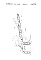
- FIG. 2 is a side view similar to FIG. 1 and including a mast;
- FIG. 3 is a side view similar to FIG. 2 showing the mast in two different positions during the process of erecting the mast;
- FIG. 4 is a side view similar to FIG. 3 showing the mast in an upright position
- FIG. 5 shows a top view of a portion of the preferred embodiment of the invention with the foot of the mast at the top of the substructure;
- FIG. 6 is a view taken along line 6--6 in FIG. 5.
- a substructure base 12 which includes a pair of elongate main frames constructed of steel elements, one of which is frame 14.
- the substructure base includes another elongate main frame (not visible), like frame 14 which is behind and spaced in parallel relation away from frame 14 as seen in FIGS. 1-4.
- a pair of front end frames, one of which is end frame 16 are pivotally attached to their associated main frames, like end frame 16 is attached to main frame 14.
- the other front end frame is to the rear of end frame 16, spaced apart therefrom and hingingly connected to the main frame behind main frame 14.
- An upright track 15, is mounted on the front of frame 16.
- a similar track (not visible) is mounted on the front of the other front end frame.
- a pair of pulleys 17, 19 are mounted for rotation at the top of end frame 16.
- the track structure and that of pulleys 17, 19 will be further described hereinafter.
- a rear end frame 18 is pivotally attached to main frame 14 opposite end frame 16.
- a pulley 21 is mounted for rotation at the top of end frame 18.
- Another rear end frame, not visible, is pivotally attached behind main frame 18, viewed in FIGS. 1-4, to the main frame behind main frame 14.
- end frames 16, 18 are shown in dashed lines in their upright configurations.
- U.S. Pat. No. 3,333,377 to Woolslayer for Assembly of Substructure-Constructing Components and Method of Constructing Tall Substructures discloses a similar substructure base with end frames which pivot into position.
- a drawworks supporting unit 20 rests on top of the substructure base and supports thereon a drawworks 22.
- Substructure base 12 the front and rear end frames and unit 20 are herein referred to collectively as a substructure.
- a conventional gin pole 23 having front legs, one of which is leg 24, the other front leg being obscured behind leg 24.
- Pulleys, one of which is pulley 28 are journaled for rotation between legs 24, 26 and the other legs.
- winches 30, 32 are mounted on substructure base 12, with each winch being mounted beneath one of the four end frames, like winch 32 is mounted beneath end-frame 16 and like winch 30 is mounted beneath end-frame 18.
- winches 30, 32 are mounted on substructure base 12, with each winch being mounted beneath one of the four end frames, like winch 32 is mounted beneath end-frame 16 and like winch 30 is mounted beneath end-frame 18.
- the other two winches are mounted on the substructure base beneath the other two end frames (also not visible).
- Winch 30 includes a line 34 which, in the configuration shown in FIG. 1, is strung over one of the pulleys on gin pole 23 and is attached to a shoe 36 adjacent the top of end frame 16.
- a line 38 from winch 32 is wound over pulley 17 (when the end frame is in its upright position) and is attached to a shoe 40 adjacent the top of end frame 18.
- a mast 42 in FIGS. 2-4 has a foot 44 and an end 46 with a conventional crown block 48 mounted on the end of the mast.
- the foot of the mast is pinned to the substructure adjacent the base thereof via a pin-and-shoe connection 50.
- a roller 51 is mounted for rotation at the foot of the mast. The structure of connection 50 and roller 51 will be described in greater detail hereinafter.
- a line 52 is wound on drawworks 22 in the usual fashion.
- line 52 is shown strung over crown block 48 and through pulleys (not visible) on a traveling block 54 in a conventional manner.
- the end of line 52 (not shown) is secured to the substructure so that when drawworks 22 reels in line 52, traveling block 54 moves toward crown block 48.
- a cable 56 is attached at one end to the traveling block and is looped over a pulley on gin pole 23 as shown in FIGS. 2-4 with the other end of cable 56 being attached to the mast as shown.
- roller 51 includes a pair of wheels 57, 58 mounted on an axle 60.
- Axle 60 is received within a cylinder 62 which is fixedly secured to mast foot 44.
- a second cylinder 64 is secured to the mast as shown and receives therethrough a pin 66.
- Mounted on the lowermost end of mast foot 44 is a pulley 67.
- a pin, similar to pin 66 may be received through holes in track 15 like pin 66 in FIG. 5, to form connection 50, shown in FIG. 2, at the lower end of the track.
- Track 15 includes a pair of edges 68, 70 against which wheels 57, 58, respectively, are rollingly engaged. As can be seen in FIGS. 1-4, track 15 extends from the top of the substructure to the bottom. A pair of u-shaped stops, also referred to therein as stop means, 72, 74 are mounted on track 15 just above the holes through which pin 66 is received. It is to be appreciated that foot 44 of the mast includes another lower portion identical to that shown in FIGS. 5 and 6 and which is received within a track, like track 15, which is mounted on the front end frame behind end frame 16 as viewed in FIGS. 1-4. Likewise, the other end frame includes pulleys similar to pulleys 17, 19 in end-frame 16.
- a pulley 77 is mounted on drawworks-supporting unit 20 as shown in FIGS. 5 and 6.
- unit 20 is pinned via pin-and-slot connections 76, 78 to end-frame 16.
- unit 20 is pinned to each of the other end frames and includes additional pulleys, like pulley 77, associated with its other pin-and-slot connections.
- the apparatus is first situated as shown in FIG. 1. That is, the end frames are pivotally secured to substructure base 12 as shown and line 34 from winch 30 is connected to shoe 36 over a pulley on gin pole 23. The line from the winch beneath the other rear end frame is connected to the shoe on its opposed front end frame (not visible) in a similar fashion. Once the lines are so connected, the winches are activated to reel in line thus pivoting each of the front end frames to an upright position as shown in dashed lines in FIG. 1 and in solid lines in FIGS. 2-4. Once so positioned the front end frames are secured to substructure base 12 via pins in a conventional fashion.
- mast 42 is positioned as shown in FIG. 2 and is pivotally secured to the base of the substructure via pin-and-shoe connection 50.
- line from the drawworks is run between crown block 48 and traveling block 54 with the end of the line being secured to substructure base 12 in a conventional fashion.
- cable 56 is connected to traveling block 54 and is placed over a pulley on gin pole 23, as shown in FIG. 2, with the other end of the cable being secured to the mast as shown.
- line 52 and cable 56 are arranged as shown in FIG. 2, the lines from winches 30, 32 are reeved over pulleys 21, 17, respectively, as shown in FIG. 2.
- Line 38 from winch 32 is thereafter reeved beneath pulley 77, in FIGS.
- each of the winches, like winch 32, associated with the front end frames is reeved over the pulleys, like pulley 19, adjacent the top of the track, like track 15, which is mounted on the end frame.
- the reeving for line 38 is shown in solid lines in FIGS. 5 and 6.
- Line 38 is reeved over pulley 19, under pulley 67 and the end thereof is fixedly secured to the top of end frame 16. It is to be appreciated that at this stage of the assembly operation, the foot of the mast is at the base of the substructure and that therefore pulleys 19, 67 are separated by a distance equal to approximately the height of the substructure.
- the drawworks is activated to begin reeling in line.
- traveling block 54 is drawn toward the crown block and the end of the mast begins pivoting upwardly, shown in dashed lines in FIG. 3.
- the pins which pivotally secure the foot of the mast to the base of the substructure via pin-and-shoe connections, like connection 50, are removed.
- the winches, like winch 32, beneath the front end frames are activated to reel in line thus pulling the foot of the mast upwardly along track 15.
- wheels 57, 58 roll upwardly along track edges 68, 70, respectively.
- cylinder 64 abuts stops 72, 74 thus preventing further upward movement.
- drawworks line is again reeled in thus further pivoting the end of the mast toward the drawworks until the mast is in a substantially upright position as shown in FIG. 4 at which point it abuts gin pole 23 thus preventing further pivotal movement.
- the top of track 15 is rounded thus enabling roller 51 to continuing rolling on track 15 until the mast assumes an upright position.
- a portion of mast foot 44 is shown in dashed lines in FIG. 6 illustrating the position of the mast in the upright position as shown in FIG. 4.
Landscapes
- Engineering & Computer Science (AREA)
- Life Sciences & Earth Sciences (AREA)
- Geology (AREA)
- Mining & Mineral Resources (AREA)
- Mechanical Engineering (AREA)
- Physics & Mathematics (AREA)
- Environmental & Geological Engineering (AREA)
- Fluid Mechanics (AREA)
- General Life Sciences & Earth Sciences (AREA)
- Geochemistry & Mineralogy (AREA)
- Earth Drilling (AREA)
Abstract
Description
Claims (22)
Priority Applications (1)
| Application Number | Priority Date | Filing Date | Title |
|---|---|---|---|
| US06/658,352 US4587778A (en) | 1984-10-05 | 1984-10-05 | Method and apparatus for erecting a drilling rig mast |
Applications Claiming Priority (1)
| Application Number | Priority Date | Filing Date | Title |
|---|---|---|---|
| US06/658,352 US4587778A (en) | 1984-10-05 | 1984-10-05 | Method and apparatus for erecting a drilling rig mast |
Publications (1)
| Publication Number | Publication Date |
|---|---|
| US4587778A true US4587778A (en) | 1986-05-13 |
Family
ID=24640897
Family Applications (1)
| Application Number | Title | Priority Date | Filing Date |
|---|---|---|---|
| US06/658,352 Expired - Fee Related US4587778A (en) | 1984-10-05 | 1984-10-05 | Method and apparatus for erecting a drilling rig mast |
Country Status (1)
| Country | Link |
|---|---|
| US (1) | US4587778A (en) |
Cited By (41)
| Publication number | Priority date | Publication date | Assignee | Title |
|---|---|---|---|---|
| AT408776B (en) * | 1998-10-13 | 2002-03-25 | Riedl Erich | POSITIONING DEVICE FOR A MAST |
| US20030172599A1 (en) * | 2002-03-13 | 2003-09-18 | Heartland Rig International, Llc | Arrangement for self-elevating drilling rig |
| US20090218139A1 (en) * | 2008-02-29 | 2009-09-03 | Robert Benjamin Donnally | Drilling rigs and erection methods |
| US20090218144A1 (en) * | 2008-02-29 | 2009-09-03 | Robert Benjamin Donnally | Drilling rig masts and methods of assembly and erecting masts |
| US20090218137A1 (en) * | 2008-02-29 | 2009-09-03 | Robert Benjamin Donnally | Drilling rig drawworks installation |
| US20090218138A1 (en) * | 2008-02-29 | 2009-09-03 | Robert Benjamin Donnally | Drilling rig structure installation and methods |
| US20120047820A1 (en) * | 2009-05-13 | 2012-03-01 | Donnally Robert B | Drilling rig mast lift systems and methods |
| US8353132B1 (en) * | 2010-04-30 | 2013-01-15 | Woolslayer Companies, Inc. | Method and apparatus for erection and disassembly of a sectional mast assembly |
| US20130180186A1 (en) * | 2012-01-16 | 2013-07-18 | National Oilwell Varco, L.P. | Collapsible substructure for a mobile drilling rig |
| US20130269268A1 (en) * | 2012-04-17 | 2013-10-17 | National Oilwell Varco, L.P. | Mobile drilling rig with telescoping substructure boxes |
| US20130305632A1 (en) * | 2012-05-18 | 2013-11-21 | Phillip Rivera, Sr. | System and Method for Erecting a Drilling Rig |
| US20140102803A1 (en) * | 2011-03-25 | 2014-04-17 | Ulstein Sea Of Solutions Bv | Derrick apparatus |
| US20140224543A1 (en) * | 2013-02-13 | 2014-08-14 | Nabors Drilling USA | Side Saddle Substructure |
| US8813436B2 (en) | 2008-02-29 | 2014-08-26 | National Oilwell Varco, L.P. | Pinned structural connection using a pin and plug arrangement |
| EP2715034A4 (en) * | 2011-06-02 | 2015-09-30 | Nat Oilwell Varco Lp | Drilling rig system with self-elevating drill floor |
| US9388599B2 (en) | 2014-02-27 | 2016-07-12 | Parsons Corporation | Wind tower erection system |
| WO2016140802A1 (en) * | 2015-03-05 | 2016-09-09 | Patterson-Uti Drilling Company Llc | Mast leg pulley |
| US9464488B2 (en) | 2013-09-30 | 2016-10-11 | National Oilwell Varco, L.P. | Performing simultaneous operations on multiple wellbore locations using a single mobile drilling rig |
| US20160340155A1 (en) * | 2015-05-22 | 2016-11-24 | Jones Ernest R | Tiltable and rotatable lifting pole assembly |
| US9670038B2 (en) | 2013-05-10 | 2017-06-06 | Devin International, Inc. | Drilling rig transfer system and method |
| US9677298B2 (en) | 2014-07-14 | 2017-06-13 | Dreco Energy Services Ulc | Mobile drilling rig |
| US9926719B2 (en) | 2013-02-13 | 2018-03-27 | Nabors Drilling Technologies Usa, Inc. | Slingshot side saddle substructure |
| US9970211B2 (en) | 2016-05-02 | 2018-05-15 | Dreco Energy Services Ulc | Guide rails for mobile drilling rig |
| US9988807B2 (en) | 2016-02-24 | 2018-06-05 | National Oilwell Varco, L.P. | Drilling rig with self-elevating drill floor |
| US10214970B1 (en) | 2018-06-12 | 2019-02-26 | Nabors Drilling Technologies Usa, Inc. | Post and non-elongated substructure drilling rig |
| US10214936B2 (en) | 2016-06-07 | 2019-02-26 | Nabors Drilling Technologies Usa, Inc. | Side saddle slingshot drilling rig |
| US10280692B2 (en) | 2013-02-13 | 2019-05-07 | Nabors Drilling Technologies Usa, Inc. | Slingshot side saddle substructure |
| US10428592B2 (en) | 2017-01-16 | 2019-10-01 | Nabors Drilling Technologies Usa, Inc. | Rig layout system |
| US10487592B1 (en) * | 2018-05-03 | 2019-11-26 | Nabors Drilling Technologies Usa, Inc. | Multi-direction traversable drilling rig |
| US10584541B2 (en) | 2016-07-28 | 2020-03-10 | Nabors Drilling Technologies Usa, Inc. | Pipe handling apparatus |
| CN110984676A (en) * | 2019-12-23 | 2020-04-10 | 国网河南省电力公司西峡县供电公司 | Auxiliary device is erect to line pole |
| US10648240B2 (en) | 2016-07-13 | 2020-05-12 | Nabors Drilling Technologies Usa, Inc. | Mast and substructure |
| US10704337B2 (en) | 2016-11-07 | 2020-07-07 | Nabors Drilling Technologies Usa, Inc. | Side-saddle cantilever mast |
| US10822924B2 (en) | 2016-03-07 | 2020-11-03 | National Oilwell Varco, L.P. | Multi-well bop cellar trailer |
| US10837238B2 (en) | 2018-07-19 | 2020-11-17 | Nabors Drilling Technologies Usa, Inc. | Side saddle slingshot continuous motion rig |
| US11021186B2 (en) | 2016-10-05 | 2021-06-01 | Dreco Energy Services Ulc | Movable rig and steering system |
| US11454067B2 (en) | 2018-08-06 | 2022-09-27 | Nov Canada Ulc | Drill floor support structures |
| US11603723B2 (en) | 2019-08-30 | 2023-03-14 | Nov Canada Ulc | Cuttings processing unit |
| US11851953B2 (en) | 2020-05-05 | 2023-12-26 | Saudi Arabian Oil Company | Mast safety system |
| US11873685B2 (en) | 2020-09-01 | 2024-01-16 | Nabors Drilling Technologies Usa, Inc. | Side saddle traversable drilling rig |
| US12054993B2 (en) | 2021-03-16 | 2024-08-06 | Nabors Drilling Technologies Usa, Inc. | Side saddle rig design with retractable top drive |
Citations (17)
| Publication number | Priority date | Publication date | Assignee | Title |
|---|---|---|---|---|
| US2695081A (en) * | 1950-04-20 | 1954-11-23 | Moore Corp Lee C | Portable well drilling apparatus |
| US2701039A (en) * | 1950-07-11 | 1955-02-01 | Moore Corp Lee C | Oil well substructure for rotary drilling |
| US2711804A (en) * | 1950-08-22 | 1955-06-28 | Moore Corp Lee C | Oil well drilling structure |
| US2822895A (en) * | 1953-02-13 | 1958-02-11 | Henry R Poetker | Collapsible derricks |
| US3016992A (en) * | 1957-10-24 | 1962-01-16 | Wilson John Hart | Stabilizer for fluid cylinder plungers of high slenderness ratio |
| US3194411A (en) * | 1962-07-30 | 1965-07-13 | Weitz S A Ets | Pivoting tower crane |
| US3228151A (en) * | 1962-02-15 | 1966-01-11 | Moore Corp Lee C | Drilling apparatus for deep oil wells |
| US3271915A (en) * | 1964-01-02 | 1966-09-13 | Moore Corp Lee C | Oil well drilling apparatus with selfraising drawworks support |
| US3333377A (en) * | 1965-08-02 | 1967-08-01 | Moore Corp Lee C | Assembly of substructure-constructing components and method of constructing tall substructures |
| US3416267A (en) * | 1964-09-21 | 1968-12-17 | Mini Petrolului | Collapsible derrick for drilling |
| US3747695A (en) * | 1971-04-06 | 1973-07-24 | Pyramid Derick And Equipment C | High floor pivoted mast drilling rig |
| US3807109A (en) * | 1972-10-19 | 1974-04-30 | Moore Corp Lee C | Oil well drilling apparatus |
| US3922825A (en) * | 1973-04-20 | 1975-12-02 | Dresser Ind | System for erecting an oil well derrick |
| US3942593A (en) * | 1973-10-17 | 1976-03-09 | Cabot Corporation | Drill rig apparatus |
| US4138805A (en) * | 1977-10-17 | 1979-02-13 | Pyramid Manufacturing Company | Wheeled portable trailer substructure for elevatable drawworks, masts and setback tower |
| US4221088A (en) * | 1979-01-02 | 1980-09-09 | Pre Corporation Mfg. Co. | Low lift, elevatable high floor drilling mast and substructure arrangement therefor |
| US4375241A (en) * | 1979-04-11 | 1983-03-01 | Union Industrielle Et D'entreprise | Drilling installation, more specifically for oil-drilling operations |
-
1984
- 1984-10-05 US US06/658,352 patent/US4587778A/en not_active Expired - Fee Related
Patent Citations (17)
| Publication number | Priority date | Publication date | Assignee | Title |
|---|---|---|---|---|
| US2695081A (en) * | 1950-04-20 | 1954-11-23 | Moore Corp Lee C | Portable well drilling apparatus |
| US2701039A (en) * | 1950-07-11 | 1955-02-01 | Moore Corp Lee C | Oil well substructure for rotary drilling |
| US2711804A (en) * | 1950-08-22 | 1955-06-28 | Moore Corp Lee C | Oil well drilling structure |
| US2822895A (en) * | 1953-02-13 | 1958-02-11 | Henry R Poetker | Collapsible derricks |
| US3016992A (en) * | 1957-10-24 | 1962-01-16 | Wilson John Hart | Stabilizer for fluid cylinder plungers of high slenderness ratio |
| US3228151A (en) * | 1962-02-15 | 1966-01-11 | Moore Corp Lee C | Drilling apparatus for deep oil wells |
| US3194411A (en) * | 1962-07-30 | 1965-07-13 | Weitz S A Ets | Pivoting tower crane |
| US3271915A (en) * | 1964-01-02 | 1966-09-13 | Moore Corp Lee C | Oil well drilling apparatus with selfraising drawworks support |
| US3416267A (en) * | 1964-09-21 | 1968-12-17 | Mini Petrolului | Collapsible derrick for drilling |
| US3333377A (en) * | 1965-08-02 | 1967-08-01 | Moore Corp Lee C | Assembly of substructure-constructing components and method of constructing tall substructures |
| US3747695A (en) * | 1971-04-06 | 1973-07-24 | Pyramid Derick And Equipment C | High floor pivoted mast drilling rig |
| US3807109A (en) * | 1972-10-19 | 1974-04-30 | Moore Corp Lee C | Oil well drilling apparatus |
| US3922825A (en) * | 1973-04-20 | 1975-12-02 | Dresser Ind | System for erecting an oil well derrick |
| US3942593A (en) * | 1973-10-17 | 1976-03-09 | Cabot Corporation | Drill rig apparatus |
| US4138805A (en) * | 1977-10-17 | 1979-02-13 | Pyramid Manufacturing Company | Wheeled portable trailer substructure for elevatable drawworks, masts and setback tower |
| US4221088A (en) * | 1979-01-02 | 1980-09-09 | Pre Corporation Mfg. Co. | Low lift, elevatable high floor drilling mast and substructure arrangement therefor |
| US4375241A (en) * | 1979-04-11 | 1983-03-01 | Union Industrielle Et D'entreprise | Drilling installation, more specifically for oil-drilling operations |
Cited By (65)
| Publication number | Priority date | Publication date | Assignee | Title |
|---|---|---|---|---|
| AT408776B (en) * | 1998-10-13 | 2002-03-25 | Riedl Erich | POSITIONING DEVICE FOR A MAST |
| US20030172599A1 (en) * | 2002-03-13 | 2003-09-18 | Heartland Rig International, Llc | Arrangement for self-elevating drilling rig |
| US20090218144A1 (en) * | 2008-02-29 | 2009-09-03 | Robert Benjamin Donnally | Drilling rig masts and methods of assembly and erecting masts |
| US8813436B2 (en) | 2008-02-29 | 2014-08-26 | National Oilwell Varco, L.P. | Pinned structural connection using a pin and plug arrangement |
| US20090218137A1 (en) * | 2008-02-29 | 2009-09-03 | Robert Benjamin Donnally | Drilling rig drawworks installation |
| US20090218138A1 (en) * | 2008-02-29 | 2009-09-03 | Robert Benjamin Donnally | Drilling rig structure installation and methods |
| US8047303B2 (en) | 2008-02-29 | 2011-11-01 | National Oilwell Varco L.P. | Drilling rig drawworks installation |
| US8250816B2 (en) | 2008-02-29 | 2012-08-28 | National Oilwell Varco L.P. | Drilling rig structure installation and methods |
| US20090218139A1 (en) * | 2008-02-29 | 2009-09-03 | Robert Benjamin Donnally | Drilling rigs and erection methods |
| US8468753B2 (en) | 2008-02-29 | 2013-06-25 | National Oilwell Varco L.P. | Drilling rigs and erection methods |
| US8549815B2 (en) | 2008-02-29 | 2013-10-08 | National Oilwell Varco L.P. | Drilling rig masts and methods of assembly and erecting masts |
| US20120047820A1 (en) * | 2009-05-13 | 2012-03-01 | Donnally Robert B | Drilling rig mast lift systems and methods |
| US8875911B2 (en) * | 2009-05-13 | 2014-11-04 | National Oilwell Varco, L.P. | Drilling rig mast lift systems and methods |
| US8353132B1 (en) * | 2010-04-30 | 2013-01-15 | Woolslayer Companies, Inc. | Method and apparatus for erection and disassembly of a sectional mast assembly |
| US20140102803A1 (en) * | 2011-03-25 | 2014-04-17 | Ulstein Sea Of Solutions Bv | Derrick apparatus |
| US10094136B2 (en) | 2011-06-02 | 2018-10-09 | Dreco Energy Services Ulc | Drilling rig system with self-elevating drill floor |
| US9458675B2 (en) | 2011-06-02 | 2016-10-04 | Dreco Energy Services Ulc | Method for assembling a drilling rig structure |
| AU2012262632B2 (en) * | 2011-06-02 | 2016-07-28 | National Oilwell Varco, L.P. | Drilling rig system with self-elevating drill floor |
| EP2715034A4 (en) * | 2011-06-02 | 2015-09-30 | Nat Oilwell Varco Lp | Drilling rig system with self-elevating drill floor |
| US9091125B2 (en) * | 2012-01-16 | 2015-07-28 | National Oilwell Varco, L.P. | Collapsible substructure for a mobile drilling rig |
| US20130180186A1 (en) * | 2012-01-16 | 2013-07-18 | National Oilwell Varco, L.P. | Collapsible substructure for a mobile drilling rig |
| US9556676B2 (en) | 2012-01-16 | 2017-01-31 | National Oilwell Varco, L.P. | Collapsible substructure for a mobile drilling rig |
| US9366053B2 (en) | 2012-04-17 | 2016-06-14 | National Oilwell Varco, L.P. | Mobile drilling rig with telescoping substructure boxes |
| US9869109B2 (en) | 2012-04-17 | 2018-01-16 | National Oilwell Varco, L.P. | Drilling rig mast erection system |
| US20130269268A1 (en) * | 2012-04-17 | 2013-10-17 | National Oilwell Varco, L.P. | Mobile drilling rig with telescoping substructure boxes |
| US9091126B2 (en) * | 2012-04-17 | 2015-07-28 | National Oilwell Varco, L.P. | Mobile drilling rig with telescoping substructure boxes |
| US20130305632A1 (en) * | 2012-05-18 | 2013-11-21 | Phillip Rivera, Sr. | System and Method for Erecting a Drilling Rig |
| US10214937B2 (en) | 2013-02-13 | 2019-02-26 | Nabors Drilling Technologies Usa, Inc. | Slingshot side saddle substructure |
| US10280692B2 (en) | 2013-02-13 | 2019-05-07 | Nabors Drilling Technologies Usa, Inc. | Slingshot side saddle substructure |
| US10221631B2 (en) | 2013-02-13 | 2019-03-05 | Nabors Drilling Technologies Usa, Inc. | Side saddle substructure |
| US20140224543A1 (en) * | 2013-02-13 | 2014-08-14 | Nabors Drilling USA | Side Saddle Substructure |
| US9926719B2 (en) | 2013-02-13 | 2018-03-27 | Nabors Drilling Technologies Usa, Inc. | Slingshot side saddle substructure |
| US10094137B2 (en) | 2013-02-13 | 2018-10-09 | Nabors Drilling Technologies Usa, Inc. | Slingshot side saddle substructure |
| US9810027B2 (en) * | 2013-02-13 | 2017-11-07 | Nabors Drilling Usa, Lp | Side saddle substructure |
| US10094176B2 (en) | 2013-02-13 | 2018-10-09 | Nabors Drilling Technologies Usa, Inc. | Side saddle substructure |
| US10407938B2 (en) | 2013-02-13 | 2019-09-10 | Nabors Drilling Technologies Usa, Inc. | Slingshot side saddle substructure |
| US9670038B2 (en) | 2013-05-10 | 2017-06-06 | Devin International, Inc. | Drilling rig transfer system and method |
| US9464488B2 (en) | 2013-09-30 | 2016-10-11 | National Oilwell Varco, L.P. | Performing simultaneous operations on multiple wellbore locations using a single mobile drilling rig |
| US9388599B2 (en) | 2014-02-27 | 2016-07-12 | Parsons Corporation | Wind tower erection system |
| US10392827B2 (en) | 2014-02-27 | 2019-08-27 | Parsons Corporation | Wind tower erection system |
| US9677298B2 (en) | 2014-07-14 | 2017-06-13 | Dreco Energy Services Ulc | Mobile drilling rig |
| US9512676B2 (en) * | 2015-03-05 | 2016-12-06 | Patterson-Uti Drilling Company Llc | Mast leg pulley |
| WO2016140802A1 (en) * | 2015-03-05 | 2016-09-09 | Patterson-Uti Drilling Company Llc | Mast leg pulley |
| US20160340155A1 (en) * | 2015-05-22 | 2016-11-24 | Jones Ernest R | Tiltable and rotatable lifting pole assembly |
| US9862578B2 (en) * | 2015-05-22 | 2018-01-09 | Kathy Jones | Tiltable and rotatable lifting pole assembly |
| US9988807B2 (en) | 2016-02-24 | 2018-06-05 | National Oilwell Varco, L.P. | Drilling rig with self-elevating drill floor |
| US10465377B2 (en) | 2016-02-24 | 2019-11-05 | National Oilwell Varco, L.P. | Drilling rig with self-elevating drill floor |
| US11549337B2 (en) | 2016-03-07 | 2023-01-10 | Nov Canada Ulc | Multi-well bop cellar trailer |
| US10822924B2 (en) | 2016-03-07 | 2020-11-03 | National Oilwell Varco, L.P. | Multi-well bop cellar trailer |
| US9970211B2 (en) | 2016-05-02 | 2018-05-15 | Dreco Energy Services Ulc | Guide rails for mobile drilling rig |
| US10214936B2 (en) | 2016-06-07 | 2019-02-26 | Nabors Drilling Technologies Usa, Inc. | Side saddle slingshot drilling rig |
| US10648240B2 (en) | 2016-07-13 | 2020-05-12 | Nabors Drilling Technologies Usa, Inc. | Mast and substructure |
| US10584541B2 (en) | 2016-07-28 | 2020-03-10 | Nabors Drilling Technologies Usa, Inc. | Pipe handling apparatus |
| US11021186B2 (en) | 2016-10-05 | 2021-06-01 | Dreco Energy Services Ulc | Movable rig and steering system |
| US10704337B2 (en) | 2016-11-07 | 2020-07-07 | Nabors Drilling Technologies Usa, Inc. | Side-saddle cantilever mast |
| US10428592B2 (en) | 2017-01-16 | 2019-10-01 | Nabors Drilling Technologies Usa, Inc. | Rig layout system |
| US10487592B1 (en) * | 2018-05-03 | 2019-11-26 | Nabors Drilling Technologies Usa, Inc. | Multi-direction traversable drilling rig |
| US10214970B1 (en) | 2018-06-12 | 2019-02-26 | Nabors Drilling Technologies Usa, Inc. | Post and non-elongated substructure drilling rig |
| US10837238B2 (en) | 2018-07-19 | 2020-11-17 | Nabors Drilling Technologies Usa, Inc. | Side saddle slingshot continuous motion rig |
| US11454067B2 (en) | 2018-08-06 | 2022-09-27 | Nov Canada Ulc | Drill floor support structures |
| US11603723B2 (en) | 2019-08-30 | 2023-03-14 | Nov Canada Ulc | Cuttings processing unit |
| CN110984676A (en) * | 2019-12-23 | 2020-04-10 | 国网河南省电力公司西峡县供电公司 | Auxiliary device is erect to line pole |
| US11851953B2 (en) | 2020-05-05 | 2023-12-26 | Saudi Arabian Oil Company | Mast safety system |
| US11873685B2 (en) | 2020-09-01 | 2024-01-16 | Nabors Drilling Technologies Usa, Inc. | Side saddle traversable drilling rig |
| US12054993B2 (en) | 2021-03-16 | 2024-08-06 | Nabors Drilling Technologies Usa, Inc. | Side saddle rig design with retractable top drive |
Similar Documents
| Publication | Publication Date | Title |
|---|---|---|
| US4587778A (en) | Method and apparatus for erecting a drilling rig mast | |
| US4478015A (en) | Cable sling arrangement for pivoting a drilling mast and drawworks elevator to a raised or reclined position in relation to a substructure support and method of cable sling string up | |
| US4831795A (en) | Drilling derrick assembly | |
| US4598509A (en) | Method and apparatus for raising and lowering a telescoping mast | |
| US4489526A (en) | Drill rig elevating floor structure | |
| US4109800A (en) | Multi-stage well-drilling mast assembly | |
| US6332501B1 (en) | Linear coiled tubing injector | |
| US3483933A (en) | Oil derrick erection and support system | |
| US6527047B1 (en) | Method and apparatus for connecting tubulars using a top drive | |
| US4371046A (en) | Apparatus for and method of drilling a hole into the ground | |
| US3747695A (en) | High floor pivoted mast drilling rig | |
| US7401656B2 (en) | Mobile drilling rig with dual carriers | |
| US4885893A (en) | Well mast structure | |
| US4630425A (en) | Erection means for portable drilling system | |
| US3271915A (en) | Oil well drilling apparatus with selfraising drawworks support | |
| US3494593A (en) | Portable mast | |
| US4473977A (en) | Erection means for portable drilling system | |
| US2271578A (en) | Collapsible mast erection | |
| US2527255A (en) | Well rig | |
| JP2001040663A (en) | Method and device for erecting leader for pile driver | |
| US4471587A (en) | Dual swing-up elevator well drilling apparatus | |
| US2705363A (en) | Method for erecting a sectional mast | |
| US2503604A (en) | Mast structure | |
| US2695081A (en) | Portable well drilling apparatus | |
| US2840198A (en) | Apparatus and method for multiple well drilling |
Legal Events
| Date | Code | Title | Description |
|---|---|---|---|
| AS | Assignment |
Owner name: LEE C. MOORE CORPORATION TULSA, OK A CORP. OF PA Free format text: ASSIGNMENT OF ASSIGNORS INTEREST.;ASSIGNOR:JENKINS, CECIL;REEL/FRAME:004329/0001 Effective date: 19841025 Owner name: LEE C. MOORE CORPORATION, A CORP. OF PA., OKLAHOMA Free format text: ASSIGNMENT OF ASSIGNORS INTEREST.;ASSIGNOR:WOOLSLAYER, HOMER J.;REEL/FRAME:004329/0003 Effective date: 19841107 |
|
| AS | Assignment |
Owner name: PITTROFF, MARGOT IRMGARD, EXECUTRIX OF ESTATE OF H Free format text: LETTERS OF TESTAMENTARY;ASSIGNOR:PITTROFF, JOHANN ERICH PITTROFF, DR. AKA PITTROFF, HANS;REEL/FRAME:004327/0591 Effective date: 19830804 |
|
| CC | Certificate of correction | ||
| REMI | Maintenance fee reminder mailed | ||
| LAPS | Lapse for failure to pay maintenance fees | ||
| STCH | Information on status: patent discontinuation |
Free format text: PATENT EXPIRED DUE TO NONPAYMENT OF MAINTENANCE FEES UNDER 37 CFR 1.362 |
|
| FP | Lapsed due to failure to pay maintenance fee |
Effective date: 19900513 |