EP3054069B1 - Système de poignée de porte de véhicule - Google Patents
Système de poignée de porte de véhicule Download PDFInfo
- Publication number
- EP3054069B1 EP3054069B1 EP16152966.4A EP16152966A EP3054069B1 EP 3054069 B1 EP3054069 B1 EP 3054069B1 EP 16152966 A EP16152966 A EP 16152966A EP 3054069 B1 EP3054069 B1 EP 3054069B1
- Authority
- EP
- European Patent Office
- Prior art keywords
- handle
- actuation element
- vehicle door
- assembly according
- door handle
- Prior art date
- Legal status (The legal status is an assumption and is not a legal conclusion. Google has not performed a legal analysis and makes no representation as to the accuracy of the status listed.)
- Active
Links
- 230000001939 inductive effect Effects 0.000 claims description 25
- 239000007769 metal material Substances 0.000 claims description 9
- 238000013461 design Methods 0.000 claims description 7
- 238000011156 evaluation Methods 0.000 claims description 5
- 238000013459 approach Methods 0.000 claims description 4
- 238000004382 potting Methods 0.000 claims description 3
- 150000001875 compounds Chemical class 0.000 claims description 2
- 210000002105 tongue Anatomy 0.000 description 12
- 239000011248 coating agent Substances 0.000 description 6
- 238000000576 coating method Methods 0.000 description 6
- 230000008859 change Effects 0.000 description 5
- 238000001514 detection method Methods 0.000 description 4
- 238000006073 displacement reaction Methods 0.000 description 3
- 230000006870 function Effects 0.000 description 3
- 239000000463 material Substances 0.000 description 3
- 230000009471 action Effects 0.000 description 1
- 238000005452 bending Methods 0.000 description 1
- 230000015572 biosynthetic process Effects 0.000 description 1
- 230000001427 coherent effect Effects 0.000 description 1
- 238000011161 development Methods 0.000 description 1
- 230000009977 dual effect Effects 0.000 description 1
- 230000008030 elimination Effects 0.000 description 1
- 238000003379 elimination reaction Methods 0.000 description 1
- 230000007613 environmental effect Effects 0.000 description 1
- 239000011888 foil Substances 0.000 description 1
- 239000002923 metal particle Substances 0.000 description 1
- 238000000034 method Methods 0.000 description 1
- 238000000465 moulding Methods 0.000 description 1
- 230000008447 perception Effects 0.000 description 1
- 230000008569 process Effects 0.000 description 1
- 230000004044 response Effects 0.000 description 1
Images


Classifications
-
- E—FIXED CONSTRUCTIONS
- E05—LOCKS; KEYS; WINDOW OR DOOR FITTINGS; SAFES
- E05B—LOCKS; ACCESSORIES THEREFOR; HANDCUFFS
- E05B85/00—Details of vehicle locks not provided for in groups E05B77/00 - E05B83/00
- E05B85/10—Handles
- E05B85/14—Handles pivoted about an axis parallel to the wing
- E05B85/16—Handles pivoted about an axis parallel to the wing a longitudinal grip part being pivoted at one end about an axis perpendicular to the longitudinal axis of the grip part
-
- E—FIXED CONSTRUCTIONS
- E05—LOCKS; KEYS; WINDOW OR DOOR FITTINGS; SAFES
- E05B—LOCKS; ACCESSORIES THEREFOR; HANDCUFFS
- E05B81/00—Power-actuated vehicle locks
- E05B81/54—Electrical circuits
- E05B81/64—Monitoring or sensing, e.g. by using switches or sensors
-
- E—FIXED CONSTRUCTIONS
- E05—LOCKS; KEYS; WINDOW OR DOOR FITTINGS; SAFES
- E05B—LOCKS; ACCESSORIES THEREFOR; HANDCUFFS
- E05B81/00—Power-actuated vehicle locks
- E05B81/54—Electrical circuits
- E05B81/64—Monitoring or sensing, e.g. by using switches or sensors
- E05B81/76—Detection of handle operation; Detection of a user approaching a handle; Electrical switching actions performed by door handles
-
- E—FIXED CONSTRUCTIONS
- E05—LOCKS; KEYS; WINDOW OR DOOR FITTINGS; SAFES
- E05B—LOCKS; ACCESSORIES THEREFOR; HANDCUFFS
- E05B17/00—Accessories in connection with locks
- E05B17/10—Illuminating devices on or for locks or keys; Transparent or translucent lock parts; Indicator lights
Definitions
- the invention relates to a vehicle door handle assembly.
- the invention relates to an outside door handle assembly with a sensor device for detecting an operation.
- the vehicle door handle assembly has a handle, wherein on an engaging side of the handle an actuating element is arranged, which is operable by an operator when gripping the handle.
- Door handles for motor vehicles are available in various designs, in particular, the door handles with a movable handle can be distinguished from those with a fixed handle.
- a handle part of the handle assembly to be undercut or engaged by the user is pivoted or translationally moved by force, and this movement is transmitted to a lock device in the door for actuation.
- the handles are arranged opposite the door largely immovable.
- electrically controlled door locks are used, which are led under the name "e-latch”.
- Such door locks are for example in the EP 0 584 499 A1 disclosed. In fixed door handles so no continuous mechanical chain of action is formed by the door handle on a door lock.
- the door lock is electrically energized in response to a detected actuation so that mechanical hardware can be reduced and cost and weight saved.
- Other door handles that have electrical sensor means are the EP 1 763 048 A1 , of the DE 20 2014 105 458 U1 as well as the EP 2 088 267 A2 refer to.
- the object of the invention is to provide an improved operator identification for door handles on motor vehicles.
- the door handle according to the invention has a handle, wherein the handle can be gripped around, under-gripped or overlapped.
- the handle is engaged behind in any section to exercise a required to open the door traction can.
- an actuator is arranged according to the invention.
- the actuating element is designed so that it is partially guided by a recess in the handle from the inside out, so a part protrudes into an inner cavity of the handle and a part of the actuating element protrudes out of the handle, outwardly and beyond the outer contour of the Handle protrudes at least slightly.
- the extent of extension, in which the actuating element projects outwardly beyond the outer contour of the handle can be extremely small. For example, a few tenths of a millimeter may be sufficient so that an operator hardly feels this survey and does not feel annoying.
- the actuating element In the interior of the handle, the actuating element is movably received, so that the actuating element for actuation through the recess of the handle is deflectable in the direction of the interior of the handle.
- An elastic return force is provided to bring the actuator back to its original position when a force is removed.
- a displacement, tilting or only deformation of the actuating element is allowed in the direction of the interior. In this case, very little freedom of movement or movement paths are sufficient.
- the handle protrudes outward beyond the outer contour of the handle, one can Be sufficient deformation, bending or the like of fractions of millimeters.
- the actuating element does not constitute a switch with a noticeable pressure point, but passes on the pressing force exerted when engaging behind in the form of a small deformation or displacement of the actuating element in the interior of the handle.
- the actuator is also at least partially formed with a metallic material.
- This metallic material is mounted in the interior of the handle on the actuator, laminated thereon, sprayed, painted or the entire actuator is mixed with a metallic material, such as a metallized plastic.
- This metallic material is essential, since an electrical assembly with at least one inductive distance sensor is arranged inside the handle. Inductive distance sensors detect changes in the position of metallic objects with respect to the distance sensor with high precision.
- the metallic material of the actuator shifts when actuated relative to the distance sensor, since the distance sensor is received stationary within the handle. Thus, a relative movement between actuator and distance sensor takes place as soon as the actuator shifts in the direction of the interior or is brought by the restoring force back to the original position.
- the actuating element is used accordingly to convey a change in distance or bearing change between the metallic components of the actuating element and the inductive distance sensor and to detect this change in distance. In this way, even small forces and thus actuating paths that occur during deformation or displacement of the actuating element detectable and coupled to the inductive distance sensor evaluation circuit is able to detect an operation of the door handle beyond doubt.
- the door handle thus formed is on the one hand very robust, the handle must not be deformable overall and also because the exterior is exposed only the mechanical actuator and also the electronic components protected inside the handle, possibly can be added in potted form.
- the actuator itself has no mandatory electrical components, it is only to ensure that metallic areas are formed in the material or on the material, which detect the distance sensors in the door handle. The mechanical components are decoupled in this way from the actual detection.
- the actuating element is formed from a plastic, which is partially covered with a metallic layer.
- the actuator on the outside so the side that touches a user, be modeled in its design of the handle surface, so that, if anything, only slight differences in perceptions are perceived in the touch.
- a metallic layer in the form of a sheet or a foil may be applied, since this area lies within the detection range of the inductive distance sensors.
- arranged in the interior of the door handle electrical assembly is formed with a circuit board on which the inductive distance sensor is formed, wherein the board is accommodated in a holder.
- the actuator is movably coupled to the bracket.
- both the electronic assembly is received in the holder and the actuator is movably coupled to this holder, so that a coherent unit is formed.
- a receptacle may be provided with an opening into which the circuit board is inserted and the actuating element may be fastened with spring elements on the holder.
- the actuating element is formed integrally with the holder.
- the design of the actuating element as a deformable tongue on the holder or receptacle for the electrical assembly is advantageous because then the holder can be formed with the actuating element in a molding process, wherein after the actuating element, if necessary, nor the metallic coating in the form of a film or a Coating is applied.
- circuit board is sealed in the holder with a potting compound.
- a potting of the electrical components provides protection of the electrical components and in particular of the inductive distance sensors and ensures a reliable function of the system.
- the door handle according to the invention is also in one embodiment in such a way that the actuating element is designed as an elongated element which extends along the longitudinal axis of a handle. Along this longitudinal extension several inductive distance sensors are arranged in the handle, which detect the approach of various portions of the actuating element.
- the actuating element can fulfill a plurality of operating functions, depending on which section of the actuating element is operated and which inductive distance sensor detects an actuation.
- the actuating element can in principle consist of an integral structure, which partially comprises metallic components, for example a plastic with metal particles.
- the actuating element can also be designed in several parts.
- a basic body made of a plastic can with a coating or a deferred component or another portion may be formed from a metallic material.
- a first, protruding from the handle portion of plastic may be formed and a second, located in the interior of the handle section may be formed of a metallic material.
- this second section which is formed from the metallic material, with spring tabs, which are supported in the interior of the handle.
- the restoring element itself will provide the required restoring force to move the actuator back to its original position after elimination of the actuating force.
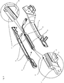
- FIG. 1 a door handle assembly 1 with a grip 2 and a handle 3 is shown.
- the handle 3 is engaged behind the door in a range between the grip 2 and handle 3.
- the handle 3 has a recess for a lock cylinder and another actuator, but these components are not essential to the invention.
- FIG. 2a the handle 3 is shown isolated from the grip 2.
- FIG. 2b the handle 3 is shown in a view from behind.
- a portion 4 of the actuating element is visible, which protrudes through an opening 5 in the handle 3.
- FIG. 3 shows the handle 3 in an open state.
- the handle 3 is formed by two housing shells, wherein the opening 5 is formed in one of the housing shells.
- an actuating unit 6 is formed in the inner cavity of the handle.
- the actuating unit has a receptacle 7 made of a plastic.
- a circuit board 8 is formed in a cavity of this receptacle 7.
- inductive distance sensors are arranged as surface mountable components and facing with their detection range of the tongue 9.
- a tongue 9 is formed on the receptacle 7 also integrally a tongue 9 is formed.
- the projecting projection 4 shown in the previous figures which protrudes through the opening 5 of the handle.
- the approach 4 is touched by the user and when force the tongue 9 is slightly deformed together with the neck 4 in the direction of the receptacle 7.
- a metallic coating 11 is pushed on on the inside of the tongue 9, which faces the receptacle 7, a metallic coating 11 is pushed.
- This metallic coating 11 is provided to trigger the arranged on the board 8 inductive distance sensors or to detect by means of the sensors the distance of this coating 11 of the inductive distance sensors.
- the actuating element is formed from a plurality of components, namely the components 9, 4 and 11.
- FIG. 4 shows a sectional view of the handle with components arranged therein in the mounted state. It is clear that the projection 4 protrudes through the outer wall of the handle 3 and protrudes slightly beyond the outer contour of the handle 3. In the illustration, the tongue 9 and the deferred metallic part 11 are visible. The metallic overthrust 11 lies opposite the printed circuit board 8 with the inductive distance sensors arranged thereon, but is separated therefrom by the receptacle 7. Tongue 9 and cap 11 are in the normal position spaced from the receptacle 7, wherein an air gap between part 11 and receptacle 7 is formed.
- a movement of the components 9, 4 and 11 causes a change in the distance of the metallic region 11 relative to the board with the inductive distance sensors. This change in distance is detected and forwarded to an evaluation device (not shown).
- the evaluation device can be formed on the circuit board 8, or the signals of the inductive distance sensors can be routed to a separate evaluation unit.
- FIG. 5 shows the actuator unit with the receptacle 7, the tongue 9 and the neck 4, wherein the metallic part 11 of the actuating element is withdrawn from the tongue 9.
- the metallic part 11 has spring tongues, which support the tongue 9 relative to the receptacle 7 and provide a restoring force which push the approach 4 through the opening of the handle 3 to the starting position as soon as no force is exerted on the neck 4 becomes.
- the metallic part 11 thus has a dual function, namely on the one hand the provision of a restoring force and on the other hand, a means which is detectable by the inductive distance sensors in the circuit 8.
Claims (9)
- Système de poignée de porte de véhicule (1) avec un dispositif à capteur pour saisir un actionnement, avec une manette (3), un élément d'actionnement (4,9,11) étant disposé sur un côté de la manette (3) pouvant être saisi par l'arrière, lequel peut être actionné par un utilisateur lors de la saisie par l'arrière de la manette (3)
caractérisé en ce que
l'élément d'actionnement (4,9,11) dépasse vers l'extérieur à travers un évidement dans la manette (3) d'un espace creux intérieur de la manette (3) à travers une paroi de la manette (3) sur le contour extérieur de la manette (3),
l'élément d'actionnement (4,9,11) étant logé pouvant être mobile à l'intérieur de la manette (3) de telle sorte que l'élément d'actionnement (4,9,11) peut être déplacé pour actionnement à travers l'évidement en direction de l'intérieur de la manette (3) en opposition à une force de rappel élastique,
l'élément d'actionnement (4,9,11) comportant au moins par tronçon un matériau métallique,
un module électrique avec au moins un capteur de distance inductif étant disposé à l'intérieur de la manette (3), le capteur de distance inductif étant logé à distance de l'élément d'actionnement (4,9,11) de façon fixe dans la manette (3) de sorte que la distance de l'élément d'actionnement (4,9,11) par rapport au capteur de distance inductif varie lors du déplacement de l'élément d'actionnement (4,9,11),
un circuit d'exploitation saisissant les signaux du capteur de distance inductif et saisissant un actionnement en fonction des signaux et fournissant un signal de sortie. - Système de poignée de porte de véhicule selon la revendication 1, l'élément d'actionnement (4,9,11) étant formé à partir d'une matière plastique, laquelle est revêtu en partie d'une couche métallique.
- Système de poignée de porte de véhicule selon la revendication 1 ou 2, le module électrique comportant une platine (8) sur laquelle est constitué un capteur de distance inductif et la platine (8) étant logée dans une fixation (7), l'élément d'actionnement (4,9,11) étant couplé pouvant être mobile avec la fixation (7).
- Système de poignée de porte de véhicule selon la revendication 3, l'élément d'actionnement (4,9,11) étant constitué intégralement avec la fixation (7), notamment sous la forme d'une languette déformable.
- Système de poignée de porte de véhicule selon la revendication 3 ou 4, la platine (8) étant coulée avec le capteur de distance inductif dans la fixation (7) avec une masse coulable.
- Système de poignée de porte de véhicule selon l'une quelconque des revendications précédentes, l'élément d'actionnement (4,9,11) étant constitué sous la forme d'un élément allongé et s'étendant le long de l'axe longitudinal de la manette (3) et plusieurs capteurs de distance inductifs étant disposés le long de l'extension longitudinale dans la manette (3), lesquels saisissent l'approche des différentes tronçons de l'élément d'actionnement (4,9,11).
- Système de poignée de porte de véhicule selon l'une quelconque des revendications précédentes, l'élément d'actionnement (4,9,11) étant constitué en plusieurs parties, un premier tronçon (4,9) dépassant de l'intérieur vers l'extérieur à travers la manette (3) étant formé d'une matière plastique et une partie métallique à l'intérieur de la manette (3) étant fixée en tant que deuxième tronçon (11) au premier tronçon.
- Système de poignée de porte de véhicule selon la revendication 7, le deuxième tronçon (11) étant constitué avec des pattes élastiques, les pattes élastiques s'appuyant à l'intérieur de la manette (3) pour fournir la force de rappel de l'élément d'actionnement (4,9,11).
- Système de poignée de porte de véhicule selon la revendication 7, le premier tronçon (4,9) de l'élément d'actionnement (4,9,11) étant formé d'une matière plastique translucide et une source de lumière étant disposée à l'intérieur de la manette (3), qui injecte de la lumière dans le premier tronçon (4,9) de telle sorte que de la lumière de la source de lumière peut être diffusée à travers le premier tronçon (4,9) dans la zone extérieure de la manette (3).
Applications Claiming Priority (1)
| Application Number | Priority Date | Filing Date | Title |
|---|---|---|---|
| DE102015101733.4A DE102015101733A1 (de) | 2015-02-06 | 2015-02-06 | Türgriffanordnung für ein Kraftfahrzeug |
Publications (2)
| Publication Number | Publication Date |
|---|---|
| EP3054069A1 EP3054069A1 (fr) | 2016-08-10 |
| EP3054069B1 true EP3054069B1 (fr) | 2018-06-27 |
Family
ID=55237579
Family Applications (1)
| Application Number | Title | Priority Date | Filing Date |
|---|---|---|---|
| EP16152966.4A Active EP3054069B1 (fr) | 2015-02-06 | 2016-01-27 | Système de poignée de porte de véhicule |
Country Status (3)
| Country | Link |
|---|---|
| US (1) | US9995065B2 (fr) |
| EP (1) | EP3054069B1 (fr) |
| DE (1) | DE102015101733A1 (fr) |
Families Citing this family (12)
| Publication number | Priority date | Publication date | Assignee | Title |
|---|---|---|---|---|
| JP6064806B2 (ja) * | 2013-06-21 | 2017-01-25 | アイシン精機株式会社 | 車両用のドアハンドル |
| CN107849866B (zh) * | 2015-07-13 | 2020-09-25 | 胡夫·许尔斯贝克和福斯特有限及两合公司 | 用于车辆的门外把手 |
| USD859955S1 (en) * | 2016-02-25 | 2019-09-17 | Southco, Inc. | Latch actuator |
| CN108473075B (zh) * | 2016-03-17 | 2020-08-04 | 株式会社本田阿克塞斯 | 辅助把手 |
| FR3065418B1 (fr) * | 2017-04-25 | 2019-04-19 | Continental Automotive France | Procede d'activation d'une fonction vehicule a partir d'un dispositif d'acces portable d et module d'activation associe |
| EP3721034A4 (fr) * | 2017-12-05 | 2021-08-18 | Adac Plastics, Inc. | Ensemble poignée de porte pour véhicule à moteur |
| DE102018107503A1 (de) * | 2018-03-28 | 2019-10-02 | Huf Hülsbeck & Fürst Gmbh & Co. Kg | Griffvorrichtung für eine Tür oder eine Klappe |
| FR3083877B1 (fr) * | 2018-07-12 | 2020-06-12 | Continental Automotive France | Module d'activation detectant simultanement une approche et un appui d'un utilisateur avec une antenne haute frequence mobile |
| DE102019109395B4 (de) | 2019-04-10 | 2023-08-24 | Dr. Ing. H.C. F. Porsche Aktiengesellschaft | Fahrzeugtür |
| DE102019206282A1 (de) * | 2019-05-02 | 2020-11-05 | Witte Automotive Gmbh | Türentriegelungs- und/oder Türöffnungsmechanismus mit einer Betätigungsvorrichtung |
| FR3096711B1 (fr) * | 2019-05-28 | 2021-07-09 | Continental Automotive Gmbh | Capteur inductif pour véhicule |
| US11719021B2 (en) | 2019-08-06 | 2023-08-08 | Schlage Lock Company Llc | Sensing and control of access control devices |
Family Cites Families (12)
| Publication number | Priority date | Publication date | Assignee | Title |
|---|---|---|---|---|
| DE4228234A1 (de) | 1992-08-25 | 1994-03-03 | Bayerische Motoren Werke Ag | Türschloß für Kraftfahrzeuge |
| DE10031664C1 (de) * | 2000-06-29 | 2002-01-03 | Kiekert Ag | Betätigungseinrichtung |
| DE10131436B4 (de) * | 2001-06-29 | 2006-07-27 | Daimlerchrysler Ag | Außentürgriff, insbesondere für Kraftfahrzeuge |
| DE10309148A1 (de) * | 2003-03-02 | 2004-09-23 | Huf Hülsbeck & Fürst Gmbh & Co. Kg | Vorrichtung zum Betätigen eines elektrischen Schließsystems und/oder eines in der Tür oder Klappe oder dergleichen eingebauten Schlosses für Fahrzeuge |
| JP4310699B2 (ja) * | 2004-06-22 | 2009-08-12 | アイシン精機株式会社 | スイッチ装置 |
| DE102005031441A1 (de) * | 2005-07-04 | 2007-01-11 | Huf Hülsbeck & Fürst Gmbh & Co. Kg | Griffvorrichtung |
| DE102008000273A1 (de) * | 2008-02-11 | 2009-08-13 | Huf Hülsbeck & Fürst Gmbh & Co. Kg | Sensoranordnung mit einem mechano-elektrischen Wandler und einem darauf einwirkenden deformierbaren mechanischen Element mit einem matastabilen Zustand |
| US8946936B2 (en) * | 2009-06-11 | 2015-02-03 | Toyota Jidosha Kabushiki Kaisha | Electromagnetic coupling device, and door handle and vehicle door having electromagnetic coupling device |
| JP5756116B2 (ja) * | 2009-11-02 | 2015-07-29 | エルジー エレクトロニクス インコーポレイティド | 洗濯方法及び洗濯機 |
| US9957737B2 (en) * | 2012-06-29 | 2018-05-01 | Ford Global Technologies, Llc | Flush-mounted door handle for vehicles |
| DE102012106526A1 (de) * | 2012-07-18 | 2014-01-23 | Huf Hülsbeck & Fürst Gmbh & Co. Kg | Handhabe mit zwei Elektroden |
| US9416565B2 (en) * | 2013-11-21 | 2016-08-16 | Ford Global Technologies, Llc | Piezo based energy harvesting for e-latch systems |
-
2015
- 2015-02-06 DE DE102015101733.4A patent/DE102015101733A1/de not_active Withdrawn
-
2016
- 2016-01-27 EP EP16152966.4A patent/EP3054069B1/fr active Active
- 2016-02-03 US US15/014,860 patent/US9995065B2/en active Active
Non-Patent Citations (1)
| Title |
|---|
| None * |
Also Published As
| Publication number | Publication date |
|---|---|
| US20160230429A1 (en) | 2016-08-11 |
| US9995065B2 (en) | 2018-06-12 |
| DE102015101733A1 (de) | 2016-08-11 |
| EP3054069A1 (fr) | 2016-08-10 |
Similar Documents
| Publication | Publication Date | Title |
|---|---|---|
| EP3054069B1 (fr) | Système de poignée de porte de véhicule | |
| EP3322868B1 (fr) | Ensemble poignée de porte pour véhicule automobile | |
| EP2633535A1 (fr) | Panneau de commande | |
| EP3097642B1 (fr) | Dispositif actionneur pour véhicule à moteur | |
| EP3049288B1 (fr) | Ensemble pour faire fonctionner une fonction de véhicule | |
| WO2017009077A1 (fr) | Ensemble poignée de porte pour véhicule automobile | |
| DE102020121603A1 (de) | Betätigungsvorrichtung mit bewegbarem Schaltelement, Fahrzeug sowie Betätigungsverfahren | |
| DE102020122424A9 (de) | Betätigungsvorrichtung zur Montage an einem Fahrzeugteil, Fahrzeug sowie Betätigungsverfahren zum Auslösen einer Fahrzeugfunktion | |
| EP2102437B1 (fr) | Poignée de porte pour véhicule automobile, dotée d'un détecteur et à réponse tactile | |
| EP2492786A1 (fr) | Elément de commande | |
| DE102013007008B4 (de) | Bedienvorrichtung für ein Kraftfahrzeug | |
| EP2088251A2 (fr) | Dispositif destiné à la libération électrique d'un processus de rinçage dans une installation sanitaire | |
| EP3149263B1 (fr) | Poignée de portière pour véhicule automobile | |
| EP2348638A2 (fr) | Commutateur de contact et/ou de rapprochement capacitif | |
| EP3462420A1 (fr) | Clé électronique par radiofréquence pour véhicules automobiles | |
| DE102015122086A1 (de) | Fahrzeugtürgriff mit Druckschalter | |
| DE102015111311A1 (de) | Türgriffanordnung für ein Kraftfahrzeug | |
| EP3205022A1 (fr) | Dispositif de commande, notamment pour appareil ménager électronique | |
| EP3262758B1 (fr) | Dispositif de commande, notamment pour appareil domestique électronique | |
| DE102018128170A1 (de) | Elektrischer Schalter und Verfahren zum Herstellen eines elektrischen Schalters | |
| WO2020169320A1 (fr) | Dispositif d'actionnement de la partie extérieure d'un véhicule automobile | |
| DE102017119235B3 (de) | Kraftfahrzeugbedienvorrichtung sowie Verfahren zur Herstellung einer zumindest teilweise elektrisch leitfähigen Bedieneinheit für eine Kraftfahrzeugbedienvorrichtung | |
| DE102017127222B4 (de) | Verfahren zum Betreiben einer kapazitiven Eingabevorrichtung; kapazitive Eingabevorrichtung; Kraftfahrzeug | |
| EP4027522A1 (fr) | Procédé de fabrication et de montage d'un dispositif de commande et dispositif de commande | |
| DE102021132388A1 (de) | Eingabevorrichtung für ein Kraftfahrzeug |
Legal Events
| Date | Code | Title | Description |
|---|---|---|---|
| PUAI | Public reference made under article 153(3) epc to a published international application that has entered the european phase |
Free format text: ORIGINAL CODE: 0009012 |
|
| AK | Designated contracting states |
Kind code of ref document: A1 Designated state(s): AL AT BE BG CH CY CZ DE DK EE ES FI FR GB GR HR HU IE IS IT LI LT LU LV MC MK MT NL NO PL PT RO RS SE SI SK SM TR |
|
| AX | Request for extension of the european patent |
Extension state: BA ME |
|
| 17P | Request for examination filed |
Effective date: 20160905 |
|
| RBV | Designated contracting states (corrected) |
Designated state(s): AL AT BE BG CH CY CZ DE DK EE ES FI FR GB GR HR HU IE IS IT LI LT LU LV MC MK MT NL NO PL PT RO RS SE SI SK SM TR |
|
| GRAP | Despatch of communication of intention to grant a patent |
Free format text: ORIGINAL CODE: EPIDOSNIGR1 |
|
| STAA | Information on the status of an ep patent application or granted ep patent |
Free format text: STATUS: GRANT OF PATENT IS INTENDED |
|
| RIC1 | Information provided on ipc code assigned before grant |
Ipc: E05B 17/10 20060101ALN20180108BHEP Ipc: E05B 81/76 20140101AFI20180108BHEP |
|
| INTG | Intention to grant announced |
Effective date: 20180206 |
|
| GRAS | Grant fee paid |
Free format text: ORIGINAL CODE: EPIDOSNIGR3 |
|
| GRAA | (expected) grant |
Free format text: ORIGINAL CODE: 0009210 |
|
| STAA | Information on the status of an ep patent application or granted ep patent |
Free format text: STATUS: THE PATENT HAS BEEN GRANTED |
|
| AK | Designated contracting states |
Kind code of ref document: B1 Designated state(s): AL AT BE BG CH CY CZ DE DK EE ES FI FR GB GR HR HU IE IS IT LI LT LU LV MC MK MT NL NO PL PT RO RS SE SI SK SM TR |
|
| REG | Reference to a national code |
Ref country code: GB Ref legal event code: FG4D Free format text: NOT ENGLISH |
|
| REG | Reference to a national code |
Ref country code: AT Ref legal event code: REF Ref document number: 1012505 Country of ref document: AT Kind code of ref document: T Effective date: 20180715 |
|
| REG | Reference to a national code |
Ref country code: IE Ref legal event code: FG4D Free format text: LANGUAGE OF EP DOCUMENT: GERMAN |
|
| REG | Reference to a national code |
Ref country code: DE Ref legal event code: R096 Ref document number: 502016001312 Country of ref document: DE |
|
| PG25 | Lapsed in a contracting state [announced via postgrant information from national office to epo] |
Ref country code: BG Free format text: LAPSE BECAUSE OF FAILURE TO SUBMIT A TRANSLATION OF THE DESCRIPTION OR TO PAY THE FEE WITHIN THE PRESCRIBED TIME-LIMIT Effective date: 20180927 Ref country code: FI Free format text: LAPSE BECAUSE OF FAILURE TO SUBMIT A TRANSLATION OF THE DESCRIPTION OR TO PAY THE FEE WITHIN THE PRESCRIBED TIME-LIMIT Effective date: 20180627 Ref country code: NO Free format text: LAPSE BECAUSE OF FAILURE TO SUBMIT A TRANSLATION OF THE DESCRIPTION OR TO PAY THE FEE WITHIN THE PRESCRIBED TIME-LIMIT Effective date: 20180927 Ref country code: SE Free format text: LAPSE BECAUSE OF FAILURE TO SUBMIT A TRANSLATION OF THE DESCRIPTION OR TO PAY THE FEE WITHIN THE PRESCRIBED TIME-LIMIT Effective date: 20180627 Ref country code: LT Free format text: LAPSE BECAUSE OF FAILURE TO SUBMIT A TRANSLATION OF THE DESCRIPTION OR TO PAY THE FEE WITHIN THE PRESCRIBED TIME-LIMIT Effective date: 20180627 |
|
| REG | Reference to a national code |
Ref country code: NL Ref legal event code: MP Effective date: 20180627 |
|
| REG | Reference to a national code |
Ref country code: LT Ref legal event code: MG4D |
|
| PG25 | Lapsed in a contracting state [announced via postgrant information from national office to epo] |
Ref country code: RS Free format text: LAPSE BECAUSE OF FAILURE TO SUBMIT A TRANSLATION OF THE DESCRIPTION OR TO PAY THE FEE WITHIN THE PRESCRIBED TIME-LIMIT Effective date: 20180627 Ref country code: HR Free format text: LAPSE BECAUSE OF FAILURE TO SUBMIT A TRANSLATION OF THE DESCRIPTION OR TO PAY THE FEE WITHIN THE PRESCRIBED TIME-LIMIT Effective date: 20180627 Ref country code: GR Free format text: LAPSE BECAUSE OF FAILURE TO SUBMIT A TRANSLATION OF THE DESCRIPTION OR TO PAY THE FEE WITHIN THE PRESCRIBED TIME-LIMIT Effective date: 20180928 Ref country code: LV Free format text: LAPSE BECAUSE OF FAILURE TO SUBMIT A TRANSLATION OF THE DESCRIPTION OR TO PAY THE FEE WITHIN THE PRESCRIBED TIME-LIMIT Effective date: 20180627 |
|
| PG25 | Lapsed in a contracting state [announced via postgrant information from national office to epo] |
Ref country code: NL Free format text: LAPSE BECAUSE OF FAILURE TO SUBMIT A TRANSLATION OF THE DESCRIPTION OR TO PAY THE FEE WITHIN THE PRESCRIBED TIME-LIMIT Effective date: 20180627 |
|
| PG25 | Lapsed in a contracting state [announced via postgrant information from national office to epo] |
Ref country code: EE Free format text: LAPSE BECAUSE OF FAILURE TO SUBMIT A TRANSLATION OF THE DESCRIPTION OR TO PAY THE FEE WITHIN THE PRESCRIBED TIME-LIMIT Effective date: 20180627 Ref country code: SK Free format text: LAPSE BECAUSE OF FAILURE TO SUBMIT A TRANSLATION OF THE DESCRIPTION OR TO PAY THE FEE WITHIN THE PRESCRIBED TIME-LIMIT Effective date: 20180627 Ref country code: IS Free format text: LAPSE BECAUSE OF FAILURE TO SUBMIT A TRANSLATION OF THE DESCRIPTION OR TO PAY THE FEE WITHIN THE PRESCRIBED TIME-LIMIT Effective date: 20181027 Ref country code: RO Free format text: LAPSE BECAUSE OF FAILURE TO SUBMIT A TRANSLATION OF THE DESCRIPTION OR TO PAY THE FEE WITHIN THE PRESCRIBED TIME-LIMIT Effective date: 20180627 Ref country code: CZ Free format text: LAPSE BECAUSE OF FAILURE TO SUBMIT A TRANSLATION OF THE DESCRIPTION OR TO PAY THE FEE WITHIN THE PRESCRIBED TIME-LIMIT Effective date: 20180627 Ref country code: PL Free format text: LAPSE BECAUSE OF FAILURE TO SUBMIT A TRANSLATION OF THE DESCRIPTION OR TO PAY THE FEE WITHIN THE PRESCRIBED TIME-LIMIT Effective date: 20180627 |
|
| PG25 | Lapsed in a contracting state [announced via postgrant information from national office to epo] |
Ref country code: SM Free format text: LAPSE BECAUSE OF FAILURE TO SUBMIT A TRANSLATION OF THE DESCRIPTION OR TO PAY THE FEE WITHIN THE PRESCRIBED TIME-LIMIT Effective date: 20180627 Ref country code: IT Free format text: LAPSE BECAUSE OF FAILURE TO SUBMIT A TRANSLATION OF THE DESCRIPTION OR TO PAY THE FEE WITHIN THE PRESCRIBED TIME-LIMIT Effective date: 20180627 Ref country code: ES Free format text: LAPSE BECAUSE OF FAILURE TO SUBMIT A TRANSLATION OF THE DESCRIPTION OR TO PAY THE FEE WITHIN THE PRESCRIBED TIME-LIMIT Effective date: 20180627 |
|
| REG | Reference to a national code |
Ref country code: DE Ref legal event code: R097 Ref document number: 502016001312 Country of ref document: DE |
|
| PLBE | No opposition filed within time limit |
Free format text: ORIGINAL CODE: 0009261 |
|
| STAA | Information on the status of an ep patent application or granted ep patent |
Free format text: STATUS: NO OPPOSITION FILED WITHIN TIME LIMIT |
|
| PG25 | Lapsed in a contracting state [announced via postgrant information from national office to epo] |
Ref country code: DK Free format text: LAPSE BECAUSE OF FAILURE TO SUBMIT A TRANSLATION OF THE DESCRIPTION OR TO PAY THE FEE WITHIN THE PRESCRIBED TIME-LIMIT Effective date: 20180627 |
|
| 26N | No opposition filed |
Effective date: 20190328 |
|
| PG25 | Lapsed in a contracting state [announced via postgrant information from national office to epo] |
Ref country code: MC Free format text: LAPSE BECAUSE OF FAILURE TO SUBMIT A TRANSLATION OF THE DESCRIPTION OR TO PAY THE FEE WITHIN THE PRESCRIBED TIME-LIMIT Effective date: 20180627 Ref country code: SI Free format text: LAPSE BECAUSE OF FAILURE TO SUBMIT A TRANSLATION OF THE DESCRIPTION OR TO PAY THE FEE WITHIN THE PRESCRIBED TIME-LIMIT Effective date: 20180627 |
|
| REG | Reference to a national code |
Ref country code: CH Ref legal event code: PL |
|
| PG25 | Lapsed in a contracting state [announced via postgrant information from national office to epo] |
Ref country code: LU Free format text: LAPSE BECAUSE OF NON-PAYMENT OF DUE FEES Effective date: 20190127 |
|
| REG | Reference to a national code |
Ref country code: BE Ref legal event code: MM Effective date: 20190131 |
|
| REG | Reference to a national code |
Ref country code: IE Ref legal event code: MM4A |
|
| PG25 | Lapsed in a contracting state [announced via postgrant information from national office to epo] |
Ref country code: AL Free format text: LAPSE BECAUSE OF FAILURE TO SUBMIT A TRANSLATION OF THE DESCRIPTION OR TO PAY THE FEE WITHIN THE PRESCRIBED TIME-LIMIT Effective date: 20180627 Ref country code: BE Free format text: LAPSE BECAUSE OF NON-PAYMENT OF DUE FEES Effective date: 20190131 |
|
| PG25 | Lapsed in a contracting state [announced via postgrant information from national office to epo] |
Ref country code: CH Free format text: LAPSE BECAUSE OF NON-PAYMENT OF DUE FEES Effective date: 20190131 Ref country code: LI Free format text: LAPSE BECAUSE OF NON-PAYMENT OF DUE FEES Effective date: 20190131 |
|
| PG25 | Lapsed in a contracting state [announced via postgrant information from national office to epo] |
Ref country code: IE Free format text: LAPSE BECAUSE OF NON-PAYMENT OF DUE FEES Effective date: 20190127 |
|
| PG25 | Lapsed in a contracting state [announced via postgrant information from national office to epo] |
Ref country code: TR Free format text: LAPSE BECAUSE OF FAILURE TO SUBMIT A TRANSLATION OF THE DESCRIPTION OR TO PAY THE FEE WITHIN THE PRESCRIBED TIME-LIMIT Effective date: 20180627 |
|
| PG25 | Lapsed in a contracting state [announced via postgrant information from national office to epo] |
Ref country code: MT Free format text: LAPSE BECAUSE OF FAILURE TO SUBMIT A TRANSLATION OF THE DESCRIPTION OR TO PAY THE FEE WITHIN THE PRESCRIBED TIME-LIMIT Effective date: 20180627 Ref country code: PT Free format text: LAPSE BECAUSE OF FAILURE TO SUBMIT A TRANSLATION OF THE DESCRIPTION OR TO PAY THE FEE WITHIN THE PRESCRIBED TIME-LIMIT Effective date: 20181029 |
|
| GBPC | Gb: european patent ceased through non-payment of renewal fee |
Effective date: 20200127 |
|
| PG25 | Lapsed in a contracting state [announced via postgrant information from national office to epo] |
Ref country code: GB Free format text: LAPSE BECAUSE OF NON-PAYMENT OF DUE FEES Effective date: 20200127 |
|
| PG25 | Lapsed in a contracting state [announced via postgrant information from national office to epo] |
Ref country code: CY Free format text: LAPSE BECAUSE OF FAILURE TO SUBMIT A TRANSLATION OF THE DESCRIPTION OR TO PAY THE FEE WITHIN THE PRESCRIBED TIME-LIMIT Effective date: 20180627 |
|
| PG25 | Lapsed in a contracting state [announced via postgrant information from national office to epo] |
Ref country code: HU Free format text: LAPSE BECAUSE OF FAILURE TO SUBMIT A TRANSLATION OF THE DESCRIPTION OR TO PAY THE FEE WITHIN THE PRESCRIBED TIME-LIMIT; INVALID AB INITIO Effective date: 20160127 |
|
| REG | Reference to a national code |
Ref country code: AT Ref legal event code: MM01 Ref document number: 1012505 Country of ref document: AT Kind code of ref document: T Effective date: 20210127 |
|
| PG25 | Lapsed in a contracting state [announced via postgrant information from national office to epo] |
Ref country code: AT Free format text: LAPSE BECAUSE OF NON-PAYMENT OF DUE FEES Effective date: 20210127 |
|
| PGFP | Annual fee paid to national office [announced via postgrant information from national office to epo] |
Ref country code: FR Payment date: 20220120 Year of fee payment: 7 |
|
| PG25 | Lapsed in a contracting state [announced via postgrant information from national office to epo] |
Ref country code: MK Free format text: LAPSE BECAUSE OF FAILURE TO SUBMIT A TRANSLATION OF THE DESCRIPTION OR TO PAY THE FEE WITHIN THE PRESCRIBED TIME-LIMIT Effective date: 20180627 |
|
| P01 | Opt-out of the competence of the unified patent court (upc) registered |
Effective date: 20230507 |
|
| PG25 | Lapsed in a contracting state [announced via postgrant information from national office to epo] |
Ref country code: FR Free format text: LAPSE BECAUSE OF NON-PAYMENT OF DUE FEES Effective date: 20230131 |
|
| PGFP | Annual fee paid to national office [announced via postgrant information from national office to epo] |
Ref country code: DE Payment date: 20240131 Year of fee payment: 9 |