EP3053704A1 - Polishing device, processing method of polishing member, modification method of polishing member, shape processing cutting tool, and surface modification tool - Google Patents
Polishing device, processing method of polishing member, modification method of polishing member, shape processing cutting tool, and surface modification tool Download PDFInfo
- Publication number
- EP3053704A1 EP3053704A1 EP14851154.6A EP14851154A EP3053704A1 EP 3053704 A1 EP3053704 A1 EP 3053704A1 EP 14851154 A EP14851154 A EP 14851154A EP 3053704 A1 EP3053704 A1 EP 3053704A1
- Authority
- EP
- European Patent Office
- Prior art keywords
- polishing
- shape
- tool
- polished
- polishing member
- Prior art date
- Legal status (The legal status is an assumption and is not a legal conclusion. Google has not performed a legal analysis and makes no representation as to the accuracy of the status listed.)
- Withdrawn
Links
- 238000005498 polishing Methods 0.000 title claims abstract description 353
- 238000005520 cutting process Methods 0.000 title claims abstract description 67
- 230000004048 modification Effects 0.000 title abstract description 7
- 238000012986 modification Methods 0.000 title abstract description 7
- 238000002715 modification method Methods 0.000 title description 2
- 238000003672 processing method Methods 0.000 title description 2
- 230000007246 mechanism Effects 0.000 claims abstract description 41
- 238000000034 method Methods 0.000 claims abstract description 32
- 230000008569 process Effects 0.000 claims abstract description 20
- 239000007788 liquid Substances 0.000 description 29
- 239000000463 material Substances 0.000 description 22
- 239000006061 abrasive grain Substances 0.000 description 18
- 239000002253 acid Substances 0.000 description 15
- 239000002585 base Substances 0.000 description 15
- -1 polyethylene Polymers 0.000 description 10
- 238000003825 pressing Methods 0.000 description 10
- 229910052751 metal Inorganic materials 0.000 description 8
- 239000002184 metal Substances 0.000 description 8
- 150000001875 compounds Chemical class 0.000 description 7
- 229920005989 resin Polymers 0.000 description 7
- 239000011347 resin Substances 0.000 description 7
- QTBSBXVTEAMEQO-UHFFFAOYSA-N Acetic acid Chemical compound CC(O)=O QTBSBXVTEAMEQO-UHFFFAOYSA-N 0.000 description 6
- NBIIXXVUZAFLBC-UHFFFAOYSA-N Phosphoric acid Chemical compound OP(O)(O)=O NBIIXXVUZAFLBC-UHFFFAOYSA-N 0.000 description 6
- KWYUFKZDYYNOTN-UHFFFAOYSA-M Potassium hydroxide Chemical compound [OH-].[K+] KWYUFKZDYYNOTN-UHFFFAOYSA-M 0.000 description 6
- QAOWNCQODCNURD-UHFFFAOYSA-N Sulfuric acid Chemical compound OS(O)(=O)=O QAOWNCQODCNURD-UHFFFAOYSA-N 0.000 description 6
- 239000000919 ceramic Substances 0.000 description 6
- 239000002738 chelating agent Substances 0.000 description 6
- KRKNYBCHXYNGOX-UHFFFAOYSA-N citric acid Chemical compound OC(=O)CC(O)(C(O)=O)CC(O)=O KRKNYBCHXYNGOX-UHFFFAOYSA-N 0.000 description 6
- 239000003002 pH adjusting agent Substances 0.000 description 6
- 238000004070 electrodeposition Methods 0.000 description 5
- 239000004745 nonwoven fabric Substances 0.000 description 5
- 150000003839 salts Chemical class 0.000 description 5
- 239000011163 secondary particle Substances 0.000 description 5
- 229920003002 synthetic resin Polymers 0.000 description 5
- 239000000057 synthetic resin Substances 0.000 description 5
- QGZKDVFQNNGYKY-UHFFFAOYSA-N Ammonia Chemical compound N QGZKDVFQNNGYKY-UHFFFAOYSA-N 0.000 description 4
- XEEYBQQBJWHFJM-UHFFFAOYSA-N Iron Chemical compound [Fe] XEEYBQQBJWHFJM-UHFFFAOYSA-N 0.000 description 4
- UQSXHKLRYXJYBZ-UHFFFAOYSA-N Iron oxide Chemical compound [Fe]=O UQSXHKLRYXJYBZ-UHFFFAOYSA-N 0.000 description 4
- PXHVJJICTQNCMI-UHFFFAOYSA-N Nickel Chemical compound [Ni] PXHVJJICTQNCMI-UHFFFAOYSA-N 0.000 description 4
- 229910052782 aluminium Inorganic materials 0.000 description 4
- XAGFODPZIPBFFR-UHFFFAOYSA-N aluminium Chemical compound [Al] XAGFODPZIPBFFR-UHFFFAOYSA-N 0.000 description 4
- 150000001412 amines Chemical class 0.000 description 4
- WPYMKLBDIGXBTP-UHFFFAOYSA-N benzoic acid Chemical compound OC(=O)C1=CC=CC=C1 WPYMKLBDIGXBTP-UHFFFAOYSA-N 0.000 description 4
- AMWRITDGCCNYAT-UHFFFAOYSA-L hydroxy(oxo)manganese;manganese Chemical compound [Mn].O[Mn]=O.O[Mn]=O AMWRITDGCCNYAT-UHFFFAOYSA-L 0.000 description 4
- 150000004767 nitrides Chemical class 0.000 description 4
- 125000005702 oxyalkylene group Chemical group 0.000 description 4
- 239000002245 particle Substances 0.000 description 4
- OFOBLEOULBTSOW-UHFFFAOYSA-N Malonic acid Chemical compound OC(=O)CC(O)=O OFOBLEOULBTSOW-UHFFFAOYSA-N 0.000 description 3
- GRYLNZFGIOXLOG-UHFFFAOYSA-N Nitric acid Chemical compound O[N+]([O-])=O GRYLNZFGIOXLOG-UHFFFAOYSA-N 0.000 description 3
- MUBZPKHOEPUJKR-UHFFFAOYSA-N Oxalic acid Chemical compound OC(=O)C(O)=O MUBZPKHOEPUJKR-UHFFFAOYSA-N 0.000 description 3
- VYPSYNLAJGMNEJ-UHFFFAOYSA-N Silicium dioxide Chemical compound O=[Si]=O VYPSYNLAJGMNEJ-UHFFFAOYSA-N 0.000 description 3
- HEMHJVSKTPXQMS-UHFFFAOYSA-M Sodium hydroxide Chemical compound [OH-].[Na+] HEMHJVSKTPXQMS-UHFFFAOYSA-M 0.000 description 3
- 229910000147 aluminium phosphate Inorganic materials 0.000 description 3
- 230000008901 benefit Effects 0.000 description 3
- 239000003795 chemical substances by application Substances 0.000 description 3
- ZZUFCTLCJUWOSV-UHFFFAOYSA-N furosemide Chemical compound C1=C(Cl)C(S(=O)(=O)N)=CC(C(O)=O)=C1NCC1=CC=CO1 ZZUFCTLCJUWOSV-UHFFFAOYSA-N 0.000 description 3
- 229910017604 nitric acid Inorganic materials 0.000 description 3
- TWNQGVIAIRXVLR-UHFFFAOYSA-N oxo(oxoalumanyloxy)alumane Chemical compound O=[Al]O[Al]=O TWNQGVIAIRXVLR-UHFFFAOYSA-N 0.000 description 3
- RVTZCBVAJQQJTK-UHFFFAOYSA-N oxygen(2-);zirconium(4+) Chemical compound [O-2].[O-2].[Zr+4] RVTZCBVAJQQJTK-UHFFFAOYSA-N 0.000 description 3
- HBMJWWWQQXIZIP-UHFFFAOYSA-N silicon carbide Chemical compound [Si+]#[C-] HBMJWWWQQXIZIP-UHFFFAOYSA-N 0.000 description 3
- 229910010271 silicon carbide Inorganic materials 0.000 description 3
- 229910052814 silicon oxide Inorganic materials 0.000 description 3
- 229910001928 zirconium oxide Inorganic materials 0.000 description 3
- QQVDJLLNRSOCEL-UHFFFAOYSA-N (2-aminoethyl)phosphonic acid Chemical compound [NH3+]CCP(O)([O-])=O QQVDJLLNRSOCEL-UHFFFAOYSA-N 0.000 description 2
- ZORQXIQZAOLNGE-UHFFFAOYSA-N 1,1-difluorocyclohexane Chemical compound FC1(F)CCCCC1 ZORQXIQZAOLNGE-UHFFFAOYSA-N 0.000 description 2
- SMNDYUVBFMFKNZ-UHFFFAOYSA-N 2-furoic acid Chemical compound OC(=O)C1=CC=CO1 SMNDYUVBFMFKNZ-UHFFFAOYSA-N 0.000 description 2
- IHCCAYCGZOLTEU-UHFFFAOYSA-N 3-furoic acid Chemical compound OC(=O)C=1C=COC=1 IHCCAYCGZOLTEU-UHFFFAOYSA-N 0.000 description 2
- 229920000178 Acrylic resin Polymers 0.000 description 2
- 239000004925 Acrylic resin Substances 0.000 description 2
- 239000005711 Benzoic acid Substances 0.000 description 2
- FERIUCNNQQJTOY-UHFFFAOYSA-N Butyric acid Chemical compound CCCC(O)=O FERIUCNNQQJTOY-UHFFFAOYSA-N 0.000 description 2
- OYPRJOBELJOOCE-UHFFFAOYSA-N Calcium Chemical compound [Ca] OYPRJOBELJOOCE-UHFFFAOYSA-N 0.000 description 2
- FEWJPZIEWOKRBE-JCYAYHJZSA-N Dextrotartaric acid Chemical compound OC(=O)[C@H](O)[C@@H](O)C(O)=O FEWJPZIEWOKRBE-JCYAYHJZSA-N 0.000 description 2
- KRHYYFGTRYWZRS-UHFFFAOYSA-N Fluorane Chemical compound F KRHYYFGTRYWZRS-UHFFFAOYSA-N 0.000 description 2
- AEMRFAOFKBGASW-UHFFFAOYSA-N Glycolic acid Chemical compound OCC(O)=O AEMRFAOFKBGASW-UHFFFAOYSA-N 0.000 description 2
- VEXZGXHMUGYJMC-UHFFFAOYSA-N Hydrochloric acid Chemical compound Cl VEXZGXHMUGYJMC-UHFFFAOYSA-N 0.000 description 2
- MHAJPDPJQMAIIY-UHFFFAOYSA-N Hydrogen peroxide Chemical compound OO MHAJPDPJQMAIIY-UHFFFAOYSA-N 0.000 description 2
- FYYHWMGAXLPEAU-UHFFFAOYSA-N Magnesium Chemical compound [Mg] FYYHWMGAXLPEAU-UHFFFAOYSA-N 0.000 description 2
- AFVFQIVMOAPDHO-UHFFFAOYSA-N Methanesulfonic acid Chemical compound CS(O)(=O)=O AFVFQIVMOAPDHO-UHFFFAOYSA-N 0.000 description 2
- KFSLWBXXFJQRDL-UHFFFAOYSA-N Peracetic acid Chemical compound CC(=O)OO KFSLWBXXFJQRDL-UHFFFAOYSA-N 0.000 description 2
- 229920003171 Poly (ethylene oxide) Polymers 0.000 description 2
- 239000004952 Polyamide Substances 0.000 description 2
- 239000004698 Polyethylene Substances 0.000 description 2
- 239000004642 Polyimide Substances 0.000 description 2
- 239000004743 Polypropylene Substances 0.000 description 2
- JUJWROOIHBZHMG-UHFFFAOYSA-N Pyridine Chemical compound C1=CC=NC=C1 JUJWROOIHBZHMG-UHFFFAOYSA-N 0.000 description 2
- XUIMIQQOPSSXEZ-UHFFFAOYSA-N Silicon Chemical compound [Si] XUIMIQQOPSSXEZ-UHFFFAOYSA-N 0.000 description 2
- FEWJPZIEWOKRBE-UHFFFAOYSA-N Tartaric acid Natural products [H+].[H+].[O-]C(=O)C(O)C(O)C([O-])=O FEWJPZIEWOKRBE-UHFFFAOYSA-N 0.000 description 2
- GWEVSGVZZGPLCZ-UHFFFAOYSA-N Titan oxide Chemical compound O=[Ti]=O GWEVSGVZZGPLCZ-UHFFFAOYSA-N 0.000 description 2
- RTAQQCXQSZGOHL-UHFFFAOYSA-N Titanium Chemical compound [Ti] RTAQQCXQSZGOHL-UHFFFAOYSA-N 0.000 description 2
- WGLPBDUCMAPZCE-UHFFFAOYSA-N Trioxochromium Chemical compound O=[Cr](=O)=O WGLPBDUCMAPZCE-UHFFFAOYSA-N 0.000 description 2
- HCHKCACWOHOZIP-UHFFFAOYSA-N Zinc Chemical compound [Zn] HCHKCACWOHOZIP-UHFFFAOYSA-N 0.000 description 2
- QCWXUUIWCKQGHC-UHFFFAOYSA-N Zirconium Chemical compound [Zr] QCWXUUIWCKQGHC-UHFFFAOYSA-N 0.000 description 2
- 235000011054 acetic acid Nutrition 0.000 description 2
- WNLRTRBMVRJNCN-UHFFFAOYSA-N adipic acid Chemical compound OC(=O)CCCCC(O)=O WNLRTRBMVRJNCN-UHFFFAOYSA-N 0.000 description 2
- 239000003513 alkali Substances 0.000 description 2
- 229910045601 alloy Inorganic materials 0.000 description 2
- 239000000956 alloy Substances 0.000 description 2
- 229910021529 ammonia Inorganic materials 0.000 description 2
- 239000000908 ammonium hydroxide Substances 0.000 description 2
- 239000003945 anionic surfactant Substances 0.000 description 2
- 230000002421 anti-septic effect Effects 0.000 description 2
- 229910052788 barium Inorganic materials 0.000 description 2
- DSAJWYNOEDNPEQ-UHFFFAOYSA-N barium atom Chemical compound [Ba] DSAJWYNOEDNPEQ-UHFFFAOYSA-N 0.000 description 2
- 235000010233 benzoic acid Nutrition 0.000 description 2
- 229910052791 calcium Inorganic materials 0.000 description 2
- 239000011575 calcium Substances 0.000 description 2
- BRPQOXSCLDDYGP-UHFFFAOYSA-N calcium oxide Chemical compound [O-2].[Ca+2] BRPQOXSCLDDYGP-UHFFFAOYSA-N 0.000 description 2
- 239000000292 calcium oxide Substances 0.000 description 2
- ODINCKMPIJJUCX-UHFFFAOYSA-N calcium oxide Inorganic materials [Ca]=O ODINCKMPIJJUCX-UHFFFAOYSA-N 0.000 description 2
- 229910000420 cerium oxide Inorganic materials 0.000 description 2
- 229910000423 chromium oxide Inorganic materials 0.000 description 2
- 235000015165 citric acid Nutrition 0.000 description 2
- 229920001577 copolymer Polymers 0.000 description 2
- 238000000151 deposition Methods 0.000 description 2
- 230000008021 deposition Effects 0.000 description 2
- 229910003460 diamond Inorganic materials 0.000 description 2
- 239000010432 diamond Substances 0.000 description 2
- XBDQKXXYIPTUBI-UHFFFAOYSA-N dimethylselenoniopropionate Natural products CCC(O)=O XBDQKXXYIPTUBI-UHFFFAOYSA-N 0.000 description 2
- 239000002270 dispersing agent Substances 0.000 description 2
- 239000003822 epoxy resin Substances 0.000 description 2
- 238000005530 etching Methods 0.000 description 2
- 230000000855 fungicidal effect Effects 0.000 description 2
- 239000000417 fungicide Substances 0.000 description 2
- CHTHALBTIRVDBM-UHFFFAOYSA-N furan-2,5-dicarboxylic acid Chemical compound OC(=O)C1=CC=C(C(O)=O)O1 CHTHALBTIRVDBM-UHFFFAOYSA-N 0.000 description 2
- 239000011521 glass Substances 0.000 description 2
- MNWFXJYAOYHMED-UHFFFAOYSA-N heptanoic acid Chemical compound CCCCCCC(O)=O MNWFXJYAOYHMED-UHFFFAOYSA-N 0.000 description 2
- FUZZWVXGSFPDMH-UHFFFAOYSA-N hexanoic acid Chemical compound CCCCCC(O)=O FUZZWVXGSFPDMH-UHFFFAOYSA-N 0.000 description 2
- 229910052742 iron Inorganic materials 0.000 description 2
- FGKJLKRYENPLQH-UHFFFAOYSA-N isocaproic acid Chemical compound CC(C)CCC(O)=O FGKJLKRYENPLQH-UHFFFAOYSA-N 0.000 description 2
- 150000004715 keto acids Chemical class 0.000 description 2
- JVTAAEKCZFNVCJ-UHFFFAOYSA-N lactic acid Chemical compound CC(O)C(O)=O JVTAAEKCZFNVCJ-UHFFFAOYSA-N 0.000 description 2
- 229910052749 magnesium Inorganic materials 0.000 description 2
- 239000011777 magnesium Substances 0.000 description 2
- 239000000395 magnesium oxide Substances 0.000 description 2
- CPLXHLVBOLITMK-UHFFFAOYSA-N magnesium oxide Inorganic materials [Mg]=O CPLXHLVBOLITMK-UHFFFAOYSA-N 0.000 description 2
- AXZKOIWUVFPNLO-UHFFFAOYSA-N magnesium;oxygen(2-) Chemical compound [O-2].[Mg+2] AXZKOIWUVFPNLO-UHFFFAOYSA-N 0.000 description 2
- WPBNNNQJVZRUHP-UHFFFAOYSA-L manganese(2+);methyl n-[[2-(methoxycarbonylcarbamothioylamino)phenyl]carbamothioyl]carbamate;n-[2-(sulfidocarbothioylamino)ethyl]carbamodithioate Chemical compound [Mn+2].[S-]C(=S)NCCNC([S-])=S.COC(=O)NC(=S)NC1=CC=CC=C1NC(=S)NC(=O)OC WPBNNNQJVZRUHP-UHFFFAOYSA-L 0.000 description 2
- 229910044991 metal oxide Inorganic materials 0.000 description 2
- 150000004706 metal oxides Chemical class 0.000 description 2
- 150000002739 metals Chemical class 0.000 description 2
- BDAGIHXWWSANSR-UHFFFAOYSA-N methanoic acid Natural products OC=O BDAGIHXWWSANSR-UHFFFAOYSA-N 0.000 description 2
- 150000007522 mineralic acids Chemical class 0.000 description 2
- 229910052759 nickel Inorganic materials 0.000 description 2
- 239000002736 nonionic surfactant Substances 0.000 description 2
- WWZKQHOCKIZLMA-UHFFFAOYSA-N octanoic acid Chemical compound CCCCCCCC(O)=O WWZKQHOCKIZLMA-UHFFFAOYSA-N 0.000 description 2
- 150000007524 organic acids Chemical class 0.000 description 2
- 239000007800 oxidant agent Substances 0.000 description 2
- 230000001590 oxidative effect Effects 0.000 description 2
- BMMGVYCKOGBVEV-UHFFFAOYSA-N oxo(oxoceriooxy)cerium Chemical compound [Ce]=O.O=[Ce]=O BMMGVYCKOGBVEV-UHFFFAOYSA-N 0.000 description 2
- 239000008188 pellet Substances 0.000 description 2
- 239000005011 phenolic resin Substances 0.000 description 2
- LCPDWSOZIOUXRV-UHFFFAOYSA-N phenoxyacetic acid Chemical compound OC(=O)COC1=CC=CC=C1 LCPDWSOZIOUXRV-UHFFFAOYSA-N 0.000 description 2
- XNGIFLGASWRNHJ-UHFFFAOYSA-N phthalic acid Chemical compound OC(=O)C1=CC=CC=C1C(O)=O XNGIFLGASWRNHJ-UHFFFAOYSA-N 0.000 description 2
- WLJVNTCWHIRURA-UHFFFAOYSA-N pimelic acid Chemical compound OC(=O)CCCCCC(O)=O WLJVNTCWHIRURA-UHFFFAOYSA-N 0.000 description 2
- 229920002647 polyamide Polymers 0.000 description 2
- 229920000515 polycarbonate Polymers 0.000 description 2
- 239000004417 polycarbonate Substances 0.000 description 2
- 229920000647 polyepoxide Polymers 0.000 description 2
- 229920000573 polyethylene Polymers 0.000 description 2
- 229920001721 polyimide Polymers 0.000 description 2
- 229920000642 polymer Polymers 0.000 description 2
- 229920001155 polypropylene Polymers 0.000 description 2
- 125000001453 quaternary ammonium group Chemical group 0.000 description 2
- YGSDEFSMJLZEOE-UHFFFAOYSA-N salicylic acid Chemical compound OC(=O)C1=CC=CC=C1O YGSDEFSMJLZEOE-UHFFFAOYSA-N 0.000 description 2
- 229910052710 silicon Inorganic materials 0.000 description 2
- 239000010703 silicon Substances 0.000 description 2
- 239000001593 sorbitan monooleate Substances 0.000 description 2
- 235000011069 sorbitan monooleate Nutrition 0.000 description 2
- 229940035049 sorbitan monooleate Drugs 0.000 description 2
- 230000003746 surface roughness Effects 0.000 description 2
- 239000011975 tartaric acid Substances 0.000 description 2
- 235000002906 tartaric acid Nutrition 0.000 description 2
- 229920002803 thermoplastic polyurethane Polymers 0.000 description 2
- 229920005992 thermoplastic resin Polymers 0.000 description 2
- 229920001187 thermosetting polymer Polymers 0.000 description 2
- 239000010936 titanium Substances 0.000 description 2
- 229910052719 titanium Inorganic materials 0.000 description 2
- OGIDPMRJRNCKJF-UHFFFAOYSA-N titanium oxide Inorganic materials [Ti]=O OGIDPMRJRNCKJF-UHFFFAOYSA-N 0.000 description 2
- NQPDZGIKBAWPEJ-UHFFFAOYSA-N valeric acid Chemical compound CCCCC(O)=O NQPDZGIKBAWPEJ-UHFFFAOYSA-N 0.000 description 2
- 229920003169 water-soluble polymer Polymers 0.000 description 2
- 239000011701 zinc Substances 0.000 description 2
- 229910052725 zinc Inorganic materials 0.000 description 2
- 229910052726 zirconium Inorganic materials 0.000 description 2
- OBETXYAYXDNJHR-SSDOTTSWSA-M (2r)-2-ethylhexanoate Chemical compound CCCC[C@@H](CC)C([O-])=O OBETXYAYXDNJHR-SSDOTTSWSA-M 0.000 description 1
- BJEPYKJPYRNKOW-REOHCLBHSA-N (S)-malic acid Chemical compound OC(=O)[C@@H](O)CC(O)=O BJEPYKJPYRNKOW-REOHCLBHSA-N 0.000 description 1
- RBNPOMFGQQGHHO-UHFFFAOYSA-N -2,3-Dihydroxypropanoic acid Natural products OCC(O)C(O)=O RBNPOMFGQQGHHO-UHFFFAOYSA-N 0.000 description 1
- SFRLSTJPMFGBDP-UHFFFAOYSA-N 1,2-diphosphonoethylphosphonic acid Chemical compound OP(O)(=O)CC(P(O)(O)=O)P(O)(O)=O SFRLSTJPMFGBDP-UHFFFAOYSA-N 0.000 description 1
- ARAFEULRMHFMDE-UHFFFAOYSA-N 1,3-oxazolidine-2,5-dione Chemical compound O=C1CNC(=O)O1 ARAFEULRMHFMDE-UHFFFAOYSA-N 0.000 description 1
- IXPNQXFRVYWDDI-UHFFFAOYSA-N 1-methyl-2,4-dioxo-1,3-diazinane-5-carboximidamide Chemical compound CN1CC(C(N)=N)C(=O)NC1=O IXPNQXFRVYWDDI-UHFFFAOYSA-N 0.000 description 1
- RTBFRGCFXZNCOE-UHFFFAOYSA-N 1-methylsulfonylpiperidin-4-one Chemical compound CS(=O)(=O)N1CCC(=O)CC1 RTBFRGCFXZNCOE-UHFFFAOYSA-N 0.000 description 1
- MXYOPVWZZKEAGX-UHFFFAOYSA-N 1-phosphonoethylphosphonic acid Chemical compound OP(=O)(O)C(C)P(O)(O)=O MXYOPVWZZKEAGX-UHFFFAOYSA-N 0.000 description 1
- OXQGTIUCKGYOAA-UHFFFAOYSA-N 2-Ethylbutanoic acid Chemical compound CCC(CC)C(O)=O OXQGTIUCKGYOAA-UHFFFAOYSA-N 0.000 description 1
- IMSODMZESSGVBE-UHFFFAOYSA-N 2-Oxazoline Chemical compound C1CN=CO1 IMSODMZESSGVBE-UHFFFAOYSA-N 0.000 description 1
- URDCARMUOSMFFI-UHFFFAOYSA-N 2-[2-[bis(carboxymethyl)amino]ethyl-(2-hydroxyethyl)amino]acetic acid Chemical compound OCCN(CC(O)=O)CCN(CC(O)=O)CC(O)=O URDCARMUOSMFFI-UHFFFAOYSA-N 0.000 description 1
- WLAMNBDJUVNPJU-UHFFFAOYSA-N 2-methylbutyric acid Chemical compound CCC(C)C(O)=O WLAMNBDJUVNPJU-UHFFFAOYSA-N 0.000 description 1
- CVKMFSAVYPAZTQ-UHFFFAOYSA-N 2-methylhexanoic acid Chemical compound CCCCC(C)C(O)=O CVKMFSAVYPAZTQ-UHFFFAOYSA-N 0.000 description 1
- MLMQPDHYNJCQAO-UHFFFAOYSA-N 3,3-dimethylbutyric acid Chemical compound CC(C)(C)CC(O)=O MLMQPDHYNJCQAO-UHFFFAOYSA-N 0.000 description 1
- OSWFIVFLDKOXQC-UHFFFAOYSA-N 4-(3-methoxyphenyl)aniline Chemical compound COC1=CC=CC(C=2C=CC(N)=CC=2)=C1 OSWFIVFLDKOXQC-UHFFFAOYSA-N 0.000 description 1
- MYWGVBFSIIZBHJ-UHFFFAOYSA-N 4-phosphonobutane-1,2,3-tricarboxylic acid Chemical compound OC(=O)CC(C(O)=O)C(C(O)=O)CP(O)(O)=O MYWGVBFSIIZBHJ-UHFFFAOYSA-N 0.000 description 1
- 229910052582 BN Inorganic materials 0.000 description 1
- PZNSFCLAULLKQX-UHFFFAOYSA-N Boron nitride Chemical compound N#B PZNSFCLAULLKQX-UHFFFAOYSA-N 0.000 description 1
- 229910001369 Brass Inorganic materials 0.000 description 1
- OKTJSMMVPCPJKN-UHFFFAOYSA-N Carbon Chemical compound [C] OKTJSMMVPCPJKN-UHFFFAOYSA-N 0.000 description 1
- 229920002134 Carboxymethyl cellulose Polymers 0.000 description 1
- RYGMFSIKBFXOCR-UHFFFAOYSA-N Copper Chemical compound [Cu] RYGMFSIKBFXOCR-UHFFFAOYSA-N 0.000 description 1
- RGHNJXZEOKUKBD-UHFFFAOYSA-N D-gluconic acid Natural products OCC(O)C(O)C(O)C(O)C(O)=O RGHNJXZEOKUKBD-UHFFFAOYSA-N 0.000 description 1
- RBNPOMFGQQGHHO-UWTATZPHSA-N D-glyceric acid Chemical compound OC[C@@H](O)C(O)=O RBNPOMFGQQGHHO-UWTATZPHSA-N 0.000 description 1
- DIWVBIXQCNRCFE-UHFFFAOYSA-N DL-alpha-Methoxyphenylacetic acid Chemical compound COC(C(O)=O)C1=CC=CC=C1 DIWVBIXQCNRCFE-UHFFFAOYSA-N 0.000 description 1
- RPNUMPOLZDHAAY-UHFFFAOYSA-N Diethylenetriamine Chemical compound NCCNCCN RPNUMPOLZDHAAY-UHFFFAOYSA-N 0.000 description 1
- QEVGZEDELICMKH-UHFFFAOYSA-N Diglycolic acid Chemical compound OC(=O)COCC(O)=O QEVGZEDELICMKH-UHFFFAOYSA-N 0.000 description 1
- KCXVZYZYPLLWCC-UHFFFAOYSA-N EDTA Chemical compound OC(=O)CN(CC(O)=O)CCN(CC(O)=O)CC(O)=O KCXVZYZYPLLWCC-UHFFFAOYSA-N 0.000 description 1
- PIICEJLVQHRZGT-UHFFFAOYSA-N Ethylenediamine Chemical compound NCCN PIICEJLVQHRZGT-UHFFFAOYSA-N 0.000 description 1
- DBVJJBKOTRCVKF-UHFFFAOYSA-N Etidronic acid Chemical compound OP(=O)(O)C(O)(C)P(O)(O)=O DBVJJBKOTRCVKF-UHFFFAOYSA-N 0.000 description 1
- RGHNJXZEOKUKBD-SQOUGZDYSA-N Gluconic acid Natural products OC[C@@H](O)[C@@H](O)[C@H](O)[C@@H](O)C(O)=O RGHNJXZEOKUKBD-SQOUGZDYSA-N 0.000 description 1
- 229920000663 Hydroxyethyl cellulose Polymers 0.000 description 1
- 239000004354 Hydroxyethyl cellulose Substances 0.000 description 1
- QPCDCPDFJACHGM-UHFFFAOYSA-N N,N-bis{2-[bis(carboxymethyl)amino]ethyl}glycine Chemical compound OC(=O)CN(CC(O)=O)CCN(CC(=O)O)CCN(CC(O)=O)CC(O)=O QPCDCPDFJACHGM-UHFFFAOYSA-N 0.000 description 1
- SUZRRICLUFMAQD-UHFFFAOYSA-N N-Methyltaurine Chemical compound CNCCS(O)(=O)=O SUZRRICLUFMAQD-UHFFFAOYSA-N 0.000 description 1
- 229910019142 PO4 Inorganic materials 0.000 description 1
- ABLZXFCXXLZCGV-UHFFFAOYSA-N Phosphorous acid Chemical compound OP(O)=O ABLZXFCXXLZCGV-UHFFFAOYSA-N 0.000 description 1
- 239000002202 Polyethylene glycol Substances 0.000 description 1
- 239000004372 Polyvinyl alcohol Substances 0.000 description 1
- 229910052581 Si3N4 Inorganic materials 0.000 description 1
- 239000005708 Sodium hypochlorite Substances 0.000 description 1
- KDYFGRWQOYBRFD-UHFFFAOYSA-N Succinic acid Natural products OC(=O)CCC(O)=O KDYFGRWQOYBRFD-UHFFFAOYSA-N 0.000 description 1
- YDONNITUKPKTIG-UHFFFAOYSA-N [Nitrilotris(methylene)]trisphosphonic acid Chemical compound OP(O)(=O)CN(CP(O)(O)=O)CP(O)(O)=O YDONNITUKPKTIG-UHFFFAOYSA-N 0.000 description 1
- 239000001361 adipic acid Substances 0.000 description 1
- 235000011037 adipic acid Nutrition 0.000 description 1
- 229910052783 alkali metal Inorganic materials 0.000 description 1
- 150000008044 alkali metal hydroxides Chemical class 0.000 description 1
- 229910001860 alkaline earth metal hydroxide Inorganic materials 0.000 description 1
- 150000005215 alkyl ethers Chemical class 0.000 description 1
- OBETXYAYXDNJHR-UHFFFAOYSA-N alpha-ethylcaproic acid Natural products CCCCC(CC)C(O)=O OBETXYAYXDNJHR-UHFFFAOYSA-N 0.000 description 1
- BJEPYKJPYRNKOW-UHFFFAOYSA-N alpha-hydroxysuccinic acid Natural products OC(=O)C(O)CC(O)=O BJEPYKJPYRNKOW-UHFFFAOYSA-N 0.000 description 1
- 150000003863 ammonium salts Chemical class 0.000 description 1
- JFCQEDHGNNZCLN-UHFFFAOYSA-N anhydrous glutaric acid Natural products OC(=O)CCCC(O)=O JFCQEDHGNNZCLN-UHFFFAOYSA-N 0.000 description 1
- 150000004982 aromatic amines Chemical class 0.000 description 1
- QRUDEWIWKLJBPS-UHFFFAOYSA-N benzotriazole Chemical compound C1=CC=C2N[N][N]C2=C1 QRUDEWIWKLJBPS-UHFFFAOYSA-N 0.000 description 1
- 239000012964 benzotriazole Substances 0.000 description 1
- KGBXLFKZBHKPEV-UHFFFAOYSA-N boric acid Chemical compound OB(O)O KGBXLFKZBHKPEV-UHFFFAOYSA-N 0.000 description 1
- 239000004327 boric acid Substances 0.000 description 1
- 239000010951 brass Substances 0.000 description 1
- KDYFGRWQOYBRFD-NUQCWPJISA-N butanedioic acid Chemical compound O[14C](=O)CC[14C](O)=O KDYFGRWQOYBRFD-NUQCWPJISA-N 0.000 description 1
- 229910052799 carbon Inorganic materials 0.000 description 1
- BVKZGUZCCUSVTD-UHFFFAOYSA-N carbonic acid Chemical compound OC(O)=O BVKZGUZCCUSVTD-UHFFFAOYSA-N 0.000 description 1
- 239000001768 carboxy methyl cellulose Substances 0.000 description 1
- 235000010948 carboxy methyl cellulose Nutrition 0.000 description 1
- 150000001732 carboxylic acid derivatives Chemical class 0.000 description 1
- 239000008112 carboxymethyl-cellulose Substances 0.000 description 1
- 239000001913 cellulose Substances 0.000 description 1
- 229920002678 cellulose Polymers 0.000 description 1
- 238000004140 cleaning Methods 0.000 description 1
- 239000011248 coating agent Substances 0.000 description 1
- 238000000576 coating method Methods 0.000 description 1
- 239000010941 cobalt Substances 0.000 description 1
- 229910017052 cobalt Inorganic materials 0.000 description 1
- GUTLYIVDDKVIGB-UHFFFAOYSA-N cobalt atom Chemical compound [Co] GUTLYIVDDKVIGB-UHFFFAOYSA-N 0.000 description 1
- RYTYSMSQNNBZDP-UHFFFAOYSA-N cobalt copper Chemical compound [Co].[Cu] RYTYSMSQNNBZDP-UHFFFAOYSA-N 0.000 description 1
- 239000002131 composite material Substances 0.000 description 1
- 229910052802 copper Inorganic materials 0.000 description 1
- 239000010949 copper Substances 0.000 description 1
- 230000007423 decrease Effects 0.000 description 1
- 230000003247 decreasing effect Effects 0.000 description 1
- ZBCBWPMODOFKDW-UHFFFAOYSA-N diethanolamine Chemical compound OCCNCCO ZBCBWPMODOFKDW-UHFFFAOYSA-N 0.000 description 1
- XPPKVPWEQAFLFU-UHFFFAOYSA-J diphosphate(4-) Chemical compound [O-]P([O-])(=O)OP([O-])([O-])=O XPPKVPWEQAFLFU-UHFFFAOYSA-J 0.000 description 1
- 235000011180 diphosphates Nutrition 0.000 description 1
- 239000006185 dispersion Substances 0.000 description 1
- 238000009826 distribution Methods 0.000 description 1
- DUYCTCQXNHFCSJ-UHFFFAOYSA-N dtpmp Chemical compound OP(=O)(O)CN(CP(O)(O)=O)CCN(CP(O)(=O)O)CCN(CP(O)(O)=O)CP(O)(O)=O DUYCTCQXNHFCSJ-UHFFFAOYSA-N 0.000 description 1
- NFDRPXJGHKJRLJ-UHFFFAOYSA-N edtmp Chemical compound OP(O)(=O)CN(CP(O)(O)=O)CCN(CP(O)(O)=O)CP(O)(O)=O NFDRPXJGHKJRLJ-UHFFFAOYSA-N 0.000 description 1
- 230000000694 effects Effects 0.000 description 1
- 230000005489 elastic deformation Effects 0.000 description 1
- 239000004744 fabric Substances 0.000 description 1
- 235000019253 formic acid Nutrition 0.000 description 1
- 239000000174 gluconic acid Substances 0.000 description 1
- 235000012208 gluconic acid Nutrition 0.000 description 1
- 150000004676 glycans Chemical class 0.000 description 1
- 238000007542 hardness measurement Methods 0.000 description 1
- 150000002391 heterocyclic compounds Chemical class 0.000 description 1
- 229940005740 hexametaphosphate Drugs 0.000 description 1
- 235000019447 hydroxyethyl cellulose Nutrition 0.000 description 1
- GTTBQSNGUYHPNK-UHFFFAOYSA-N hydroxymethylphosphonic acid Chemical compound OCP(O)(O)=O GTTBQSNGUYHPNK-UHFFFAOYSA-N 0.000 description 1
- 239000004310 lactic acid Substances 0.000 description 1
- 235000014655 lactic acid Nutrition 0.000 description 1
- 239000002649 leather substitute Substances 0.000 description 1
- VZCYOOQTPOCHFL-UPHRSURJSA-N maleic acid Chemical compound OC(=O)\C=C/C(O)=O VZCYOOQTPOCHFL-UPHRSURJSA-N 0.000 description 1
- 239000011976 maleic acid Substances 0.000 description 1
- 239000001630 malic acid Substances 0.000 description 1
- 235000011090 malic acid Nutrition 0.000 description 1
- 238000005259 measurement Methods 0.000 description 1
- 229940098779 methanesulfonic acid Drugs 0.000 description 1
- RMIODHQZRUFFFF-UHFFFAOYSA-N methoxyacetic acid Chemical compound COCC(O)=O RMIODHQZRUFFFF-UHFFFAOYSA-N 0.000 description 1
- PSZYNBSKGUBXEH-UHFFFAOYSA-N naphthalene-1-sulfonic acid Chemical compound C1=CC=C2C(S(=O)(=O)O)=CC=CC2=C1 PSZYNBSKGUBXEH-UHFFFAOYSA-N 0.000 description 1
- MGFYIUFZLHCRTH-UHFFFAOYSA-N nitrilotriacetic acid Chemical compound OC(=O)CN(CC(O)=O)CC(O)=O MGFYIUFZLHCRTH-UHFFFAOYSA-N 0.000 description 1
- 238000005457 optimization Methods 0.000 description 1
- 150000007530 organic bases Chemical class 0.000 description 1
- 235000006408 oxalic acid Nutrition 0.000 description 1
- FJKROLUGYXJWQN-UHFFFAOYSA-N papa-hydroxy-benzoic acid Natural products OC(=O)C1=CC=C(O)C=C1 FJKROLUGYXJWQN-UHFFFAOYSA-N 0.000 description 1
- 229960003330 pentetic acid Drugs 0.000 description 1
- VLTRZXGMWDSKGL-UHFFFAOYSA-M perchlorate Inorganic materials [O-]Cl(=O)(=O)=O VLTRZXGMWDSKGL-UHFFFAOYSA-M 0.000 description 1
- VLTRZXGMWDSKGL-UHFFFAOYSA-N perchloric acid Chemical compound OCl(=O)(=O)=O VLTRZXGMWDSKGL-UHFFFAOYSA-N 0.000 description 1
- JRKICGRDRMAZLK-UHFFFAOYSA-L peroxydisulfate Chemical compound [O-]S(=O)(=O)OOS([O-])(=O)=O JRKICGRDRMAZLK-UHFFFAOYSA-L 0.000 description 1
- 150000002989 phenols Chemical class 0.000 description 1
- NBIIXXVUZAFLBC-UHFFFAOYSA-K phosphate Chemical compound [O-]P([O-])([O-])=O NBIIXXVUZAFLBC-UHFFFAOYSA-K 0.000 description 1
- 239000010452 phosphate Substances 0.000 description 1
- ACVYVLVWPXVTIT-UHFFFAOYSA-N phosphinic acid Chemical compound O[PH2]=O ACVYVLVWPXVTIT-UHFFFAOYSA-N 0.000 description 1
- 229920000172 poly(styrenesulfonic acid) Polymers 0.000 description 1
- 229920000058 polyacrylate Polymers 0.000 description 1
- 229920001223 polyethylene glycol Polymers 0.000 description 1
- 229920001282 polysaccharide Polymers 0.000 description 1
- 239000005017 polysaccharide Substances 0.000 description 1
- 229940005642 polystyrene sulfonic acid Drugs 0.000 description 1
- 229920002451 polyvinyl alcohol Polymers 0.000 description 1
- 229920000036 polyvinylpyrrolidone Polymers 0.000 description 1
- 239000001267 polyvinylpyrrolidone Substances 0.000 description 1
- 235000013855 polyvinylpyrrolidone Nutrition 0.000 description 1
- 235000019260 propionic acid Nutrition 0.000 description 1
- UMJSCPRVCHMLSP-UHFFFAOYSA-N pyridine Natural products COC1=CC=CN=C1 UMJSCPRVCHMLSP-UHFFFAOYSA-N 0.000 description 1
- IUVKMZGDUIUOCP-BTNSXGMBSA-N quinbolone Chemical compound O([C@H]1CC[C@H]2[C@H]3[C@@H]([C@]4(C=CC(=O)C=C4CC3)C)CC[C@@]21C)C1=CCCC1 IUVKMZGDUIUOCP-BTNSXGMBSA-N 0.000 description 1
- 229960004889 salicylic acid Drugs 0.000 description 1
- HQVNEWCFYHHQES-UHFFFAOYSA-N silicon nitride Chemical compound N12[Si]34N5[Si]62N3[Si]51N64 HQVNEWCFYHHQES-UHFFFAOYSA-N 0.000 description 1
- 235000010413 sodium alginate Nutrition 0.000 description 1
- 239000000661 sodium alginate Substances 0.000 description 1
- 229940005550 sodium alginate Drugs 0.000 description 1
- SUKJFIGYRHOWBL-UHFFFAOYSA-N sodium hypochlorite Chemical compound [Na+].Cl[O-] SUKJFIGYRHOWBL-UHFFFAOYSA-N 0.000 description 1
- MWNQXXOSWHCCOZ-UHFFFAOYSA-L sodium;oxido carbonate Chemical compound [Na+].[O-]OC([O-])=O MWNQXXOSWHCCOZ-UHFFFAOYSA-L 0.000 description 1
- 239000010935 stainless steel Substances 0.000 description 1
- 229910001220 stainless steel Inorganic materials 0.000 description 1
- 239000000126 substance Substances 0.000 description 1
- ISIJQEHRDSCQIU-UHFFFAOYSA-N tert-butyl 2,7-diazaspiro[4.5]decane-7-carboxylate Chemical compound C1N(C(=O)OC(C)(C)C)CCCC11CNCC1 ISIJQEHRDSCQIU-UHFFFAOYSA-N 0.000 description 1
- UJJLJRQIPMGXEZ-UHFFFAOYSA-N tetrahydro-2-furoic acid Chemical compound OC(=O)C1CCCO1 UJJLJRQIPMGXEZ-UHFFFAOYSA-N 0.000 description 1
- USFPINLPPFWTJW-UHFFFAOYSA-N tetraphenylphosphonium Chemical class C1=CC=CC=C1[P+](C=1C=CC=CC=1)(C=1C=CC=CC=1)C1=CC=CC=C1 USFPINLPPFWTJW-UHFFFAOYSA-N 0.000 description 1
- 150000003536 tetrazoles Chemical class 0.000 description 1
- UAXOELSVPTZZQG-UHFFFAOYSA-N tiglic acid Natural products CC(C)=C(C)C(O)=O UAXOELSVPTZZQG-UHFFFAOYSA-N 0.000 description 1
- VZCYOOQTPOCHFL-UHFFFAOYSA-N trans-butenedioic acid Natural products OC(=O)C=CC(O)=O VZCYOOQTPOCHFL-UHFFFAOYSA-N 0.000 description 1
- 150000003852 triazoles Chemical class 0.000 description 1
- AQLJVWUFPCUVLO-UHFFFAOYSA-N urea hydrogen peroxide Chemical compound OO.NC(N)=O AQLJVWUFPCUVLO-UHFFFAOYSA-N 0.000 description 1
- 229940005605 valeric acid Drugs 0.000 description 1
- XLYOFNOQVPJJNP-UHFFFAOYSA-N water Substances O XLYOFNOQVPJJNP-UHFFFAOYSA-N 0.000 description 1
- 239000000230 xanthan gum Substances 0.000 description 1
- 235000010493 xanthan gum Nutrition 0.000 description 1
- 229920001285 xanthan gum Polymers 0.000 description 1
- 229940082509 xanthan gum Drugs 0.000 description 1
Images



Classifications
-
- B—PERFORMING OPERATIONS; TRANSPORTING
- B24—GRINDING; POLISHING
- B24B—MACHINES, DEVICES, OR PROCESSES FOR GRINDING OR POLISHING; DRESSING OR CONDITIONING OF ABRADING SURFACES; FEEDING OF GRINDING, POLISHING, OR LAPPING AGENTS
- B24B53/00—Devices or means for dressing or conditioning abrasive surfaces
- B24B53/06—Devices or means for dressing or conditioning abrasive surfaces of profiled abrasive wheels
- B24B53/07—Devices or means for dressing or conditioning abrasive surfaces of profiled abrasive wheels by means of forming tools having a shape complementary to that to be produced, e.g. blocks, profile rolls
-
- B—PERFORMING OPERATIONS; TRANSPORTING
- B24—GRINDING; POLISHING
- B24B—MACHINES, DEVICES, OR PROCESSES FOR GRINDING OR POLISHING; DRESSING OR CONDITIONING OF ABRADING SURFACES; FEEDING OF GRINDING, POLISHING, OR LAPPING AGENTS
- B24B19/00—Single-purpose machines or devices for particular grinding operations not covered by any other main group
- B24B19/08—Single-purpose machines or devices for particular grinding operations not covered by any other main group for grinding non-circular cross-sections, e.g. shafts of elliptical or polygonal cross-section
-
- B—PERFORMING OPERATIONS; TRANSPORTING
- B24—GRINDING; POLISHING
- B24B—MACHINES, DEVICES, OR PROCESSES FOR GRINDING OR POLISHING; DRESSING OR CONDITIONING OF ABRADING SURFACES; FEEDING OF GRINDING, POLISHING, OR LAPPING AGENTS
- B24B53/00—Devices or means for dressing or conditioning abrasive surfaces
- B24B53/02—Devices or means for dressing or conditioning abrasive surfaces of plane surfaces on abrasive tools
-
- B—PERFORMING OPERATIONS; TRANSPORTING
- B24—GRINDING; POLISHING
- B24B—MACHINES, DEVICES, OR PROCESSES FOR GRINDING OR POLISHING; DRESSING OR CONDITIONING OF ABRADING SURFACES; FEEDING OF GRINDING, POLISHING, OR LAPPING AGENTS
- B24B53/00—Devices or means for dressing or conditioning abrasive surfaces
- B24B53/12—Dressing tools; Holders therefor
-
- B—PERFORMING OPERATIONS; TRANSPORTING
- B24—GRINDING; POLISHING
- B24B—MACHINES, DEVICES, OR PROCESSES FOR GRINDING OR POLISHING; DRESSING OR CONDITIONING OF ABRADING SURFACES; FEEDING OF GRINDING, POLISHING, OR LAPPING AGENTS
- B24B9/00—Machines or devices designed for grinding edges or bevels on work or for removing burrs; Accessories therefor
- B24B9/02—Machines or devices designed for grinding edges or bevels on work or for removing burrs; Accessories therefor characterised by a special design with respect to properties of materials specific to articles to be ground
- B24B9/06—Machines or devices designed for grinding edges or bevels on work or for removing burrs; Accessories therefor characterised by a special design with respect to properties of materials specific to articles to be ground of non-metallic inorganic material, e.g. stone, ceramics, porcelain
- B24B9/065—Machines or devices designed for grinding edges or bevels on work or for removing burrs; Accessories therefor characterised by a special design with respect to properties of materials specific to articles to be ground of non-metallic inorganic material, e.g. stone, ceramics, porcelain of thin, brittle parts, e.g. semiconductors, wafers
Definitions
- the present invention relates to a polishing device, a method for processing a polishing member, a method for modifying the polishing member, a shape-processing cutting tool, and a surface modifying tool.
- Patent document 1 describes that when a portion to be polished of a workpiece (object to be polished) is polished with a polishing member, the shape of a polishing surface of the polishing member gradually changes. Generally, dressing is performed to modify the polishing surface and return it to its original shape.
- Patent Document 1 Japanese Laid-Open Patent Publication No. 11-188590
- the present invention is made in view of such circumstances, and its objective is to provide a polishing device, a method for processing a polishing member, and a method for modifying the polishing member that allow shape processing and shape modification to be easily performed on a polishing surface having a non-planar shape. Also, it is an object of the present invention to provide a shape-processing cutting tool used in the polishing device or the processing method to process the shape of the polishing surface or a surface modifying tool used in the polishing device or the modification method to modify the polishing surface to be shaped in conformance with the shape of a portion to be polished.
- a polishing device includes a polishing member, a shape-processing cutting tool or a surface modifying tool, and a contact mechanism.
- the polishing member includes a polishing surface that is shaped in conformance with the shape of a portion to be polished of a workpiece.
- the shape-processing tool has the same shape as the portion to be polished and processes the polishing surface to be shaped in conformance with the shape of the portion to be polished.
- the surface modifying tool has the same shape as the portion to be polished and modifies the polishing surface to be shaped in conformance with the shape of the portion to be polished.
- the contact mechanism brings the shape-processing cutting tool or the surface modifying tool into contact with the polishing surface.
- the polishing member includes a polishing surface that is shaped in conformance with the shape of a portion to be polished of a workpiece.
- the portion to be polished of the workpiece can be polished even when having a non-planar shape, for example, a curved surface or a triangular shape.
- the contact mechanism brings a shape-processing cutting tool or a surface modifying tool into contact with the polishing surface.
- the shape-processing cutting tool has the same shape as the portion to be polished and processes the polishing surface to be shaped in conformance with the shape of the portion to be polished.
- the surface modifying tool has the same shape as the portion to be polished and modifies the polishing surface to be shaped in conformance with the shape of the portion to be polished.
- the polishing surface which is in contact with the shape-processing cutting tool or the surface modifying tool, copies the shape of the shape-processing cutting tool or the surface modifying tool that has the same shape as the portion to be polished of the workpiece.
- the polishing surface of the polishing member is shaped in conformance with the shape of the portion to be polished of the workpiece, the shape of the polishing surface and the shape of each of the shape-processing cutting tool and the surface modifying tool have the relationship in which one is concave and the other is convex. This allows the shape of the polishing surface having a non-planar shape to be easily processed or modified.
- the portion to be polished of the workpiece and the shape-processing cutting tool or the surface modifying tool do not need to have exactly the same shape as each other and may have slightly different shapes from each other as long as no practical problem occurs.
- the shape-processing cutting tool is configured to process the polishing surface of the polishing member and is not particularly limited as long as it includes a processing portion having higher hardness than the polishing surface of the polishing member.
- a processing tool including fixed abrasive grains, such as pellets or an electrode position whetstone, and a cutting tool, such as an end mill or a bit.
- the surface modifying tool is configured to adjust the surface of the polishing member and to remove grime or deposition from the surface of the polishing member.
- Specific examples include a processing tool including fixed abrasive grains and a hard brush.
- the contact mechanism brings the shape-processing cutting tool or the surface modifying tool into contact with the polishing surface preferably in predetermined cycles.
- the polishing surface is processed or modified in each predetermined cycle. This appropriately maintains the accuracy for polishing the workpiece.
- the polishing surface of the polishing member be formed to be shaped in conformance with the shape of the portion to be polished.
- the polishing surface is formed in the polishing device.
- the shape of the polishing surface may be formed with high accuracy compared to when the polishing member including the polishing surface that is formed in advance in conformance with the shape of the portion to be polished of the workpiece is coupled to the polishing device.
- the polishing device preferably includes a motor that rotates the polishing member from below.
- the polishing device preferably includes a base including an upper surface. When the polishing member is located on the upper surface, the base is rotated integrally with the polishing member.
- the polishing device includes a shape-processing cutting tool that has the same shape as the portion to be polished and processes the polishing surface to be shaped in conformance with the shape of the portion to be polished or a surface modifying tool that has the same shape as the portion to be polished and modifies the polishing surface to be shaped in conformance with the shape of the portion to be polished, the shape of the polishing surface having a non-planar shape can be easily processed or modified.
- a method for processing or modifying a polishing member includes bringing a shape-processing cutting tool or a surface modifying tool into contact with a polishing surface of the polishing member.
- the polishing surface is shaped in conformance with the shape of a portion to be polished of a workpiece.
- the shape-processing cutting tool has the same shape as the portion to be polished and processes the polishing surface to be shaped in conformance with the shape of the portion to be polished.
- the surface modifying tool has the same shape as the portion to be polished and modifies the polishing surface to be shaped in conformance with the shape of the portion to be polished.
- the polishing member is prepared that includes a polishing surface shaped in conformance with the shape of a portion to be polished of a workpiece.
- the portion to be polished of the workpiece can be polished even when having a non-planar shape, for example, a curved surface or a triangular shape.
- the shape-processing cutting tool which has the same shape as the portion to be polished and processes the polishing surface to be shaped in conformance with the shape of the portion to be polished
- the surface modifying tool which has the same shape as the portion to be polished and modifies the polishing surface to be shaped in conformance with the portion to be polished
- the polishing surface which is in contact with the shape-processing cutting tool or the surface modifying tool, copies the shape of the shape-processing cutting tool or the surface modifying tool that has the same shape as the portion to be polished of the workpiece. This modifies the polishing surface to be shaped in conformance with the shape of the portion to be polished of the workpiece.
- the polishing surface of the polishing member is shaped in conformance with the shape of the portion to be polished of the workpiece, the shape of the polishing surface and the shape of each of the shape-processing cutting tool and the surface modifying tool have the relationship in which one is concave and the other is convex. This allows the shape of the polishing surface having a non-planar shape to be easily modified.
- the present invention succeeds in facilitating shape processing or shape modification of a polishing surface having a non-planar shape.
- a polishing device, a method for modifying a polishing member, a shape-processing cutting tool, and a surface modifying tool according to one embodiment of the present invention will now be described with reference to Figs. 1 to 4 .
- the polishing device includes a discoid polishing member 10.
- the polishing member 10 includes a radially outer circumferential surface that is used to polish an end KE of a workpiece K, which is a portion to be polished.
- the end KE is machined in advance to have a curved surface.
- the workpiece K may have any shape, for example, in accordance with its application.
- any optimal material for polishing the end KE may be used for the polishing member 10.
- a resin is used as the material of the polishing member 10
- any synthetic resin may be used.
- a synthetic resin include a thermosetting resin (phenol resin, epoxy resin, urethane resin, polyimide, etc.) and a thermoplastic resin (polyethylene, polypropylene, acrylic resin, polyamide, polycarbonate, etc.).
- a cloth, a non-woven fabric, a resin processed non-woven fabric, synthetic leather, or a composite thereof may be used.
- the polishing surface of the polishing member 10 preferably has a Shore A hardness of 5 or greater.
- a polishing member 10 having a shore A hardness of 5 or greater which is subject to hardness measurement, is left for 60 minutes or longer in a dry condition where the humidity is 20% to 60% under room temperature, the hardness of the polishing surface of the polishing member is then measured with a durometer (type A) that is compliance with JIS K6253, and the measured value is 5 or greater.
- a durometer type A
- JIS K6253 JIS K6253
- the Shore A hardness of the polishing surface of the polishing member 10 is preferably 40 or greater, more preferably 70 to 95, and particularly preferably 70 to 85.
- magnesium, aluminum, titanium, iron, nickel, cobalt copper, zinc, manganese, or an alloy of which the main component is any of these metals may be used.
- the polishing member 10 may include abrasive grains.
- the kind of the used abrasive grains is not particularly limited and may be metal oxide particles of silicon oxide, aluminum oxide, zirconium oxide, cerium oxide, magnesium oxide, calcium oxide, titanium oxide, manganese oxide, iron oxide, or chromium oxide; a carbide, such as silicon carbide; a nitride; a boride; or a diamond.
- any of ceramics and glass any of ceramics and glass; any of an oxide, nitride, boride, and carbide of silicon, aluminum, zirconium, calcium, and barium; or any of aluminum oxide, zirconium oxide, silicon oxide, silicon carbide, silicon nitride, and boron nitride may be used.
- any material may be used for the workpiece K.
- any synthetic resin may be used.
- a synthetic resin include a thermosetting resin (phenol resin, epoxy resin, urethane resin, polyimide, etc.) and a thermoplastic resin (polyethylene, polypropylene, acrylic resin, polyamide, polycarbonate, etc.).
- any of ceramics, glass, and fine ceramics any of ceramics, glass, and fine ceramics; any of an oxide, carbide, nitride, and boride of silicon, aluminum, zirconium, calcium, and barium may be used.
- magnesium, aluminum, titanium, iron, nickel, cobalt, copper, zinc, manganese, or an alloy of which the main component is any of these metals may be used.
- the workpiece K may be used for any purpose.
- the workpiece K may be used as a wheel, a shaft, a container, a casing (for example, case and housing), a frame, a ball, a wire, an ornament, or the like.
- the polishing member 10 is fixed to the upper surface of a discoid base 20 in a removable manner.
- the lower surface of the base 20 includes a center portion that is fixed to a rotation shaft of a first motor 21.
- the first motor 21 is driven to be rotated, the base 20 and the polishing member 10 rotate.
- the first motor 21 is located below the polishing member 10 and the base 20.
- the polishing member 10, which is located on the upper surface of the base 20, is rotated together with the base 20 from below. This obtains stable rotation of the polishing member 10 with a small axial run-out and allows for polishing to be performed with higher accuracy.
- the radially outer circumferential surface of the polishing member 10 includes a polishing surface 11, which is a curved grooved surface that circumferentially extends.
- the curvature of the polishing surface 11 is shaped in conformance with the shape of the end KE of the workpiece K (shape of portion to be polished). More specifically, the polishing surface 11 and the end KE have the same curvature.
- the workpiece K is held by a fixing seat 32 in a removable manner.
- the fixing seat 32 is fixed to a rotation shaft 31 of a second motor 30.
- the second motor 30 is coupled to a motor moving mechanism 33 that reciprocates the second motor 30 in directions orthogonal to a rotation axis of the polishing member 10 (directions of arrows X shown in Figs. 1 and 2 ).
- the motor moving mechanism 33 moves the second motor 30, the second motor 30, the rotation shaft 31, the fixing seat 32, and the workpiece K are integrally move in the directions orthogonal to the rotation axis of the polishing member 10.
- Such movement of the second motor 30 caused by the motor moving mechanism 33 presses the end KE of the workpiece K against the polishing surface 11.
- a contact portion of the end KE and the polishing surface 11 is appropriately supplied with, for example, a processing liquid, and each of the first motor 21 and the second motor 30 is driven at a predetermined rotation speed. This polishes the end KE having the curved surface.
- the pressing force is adjusted so that predetermined pressure is applied.
- the processing liquid may be directly supplied to the contact portion of the end KE and the polishing surface 11 from the outer side.
- a processing liquid supply mechanism such as a rotary joint may be arranged in a portion that connects the polishing member 10 and the first motor 21.
- the processing liquid supply mechanism supplies the processing liquid into the polishing member 10
- the processing liquid may be supplied from the polishing member 10 to the contact portion through a supply passage formed in the polishing member 10.
- the processing liquid may be further efficiently supplied.
- a cover be arranged around the polishing member 10 and that a collection device be provided to increase the efficiency for collecting the processing liquid.
- a suitable kind of the processing liquid may be used in accordance with the material of the workpiece K to be polished and the polishing member 10. Specifically, a cutting liquid, grinding liquid, a lapping material, a polishing agent, or a chemical mechanical polishing liquid may be used.
- the processing liquid may include abrasive grains.
- the kind of the used abrasive grains is not particularly limited and may be metal oxide particles of silicon oxide, aluminum oxide, zirconium oxide, cerium oxide, magnesium oxide, calcium oxide, titanium oxide, manganese oxide, iron oxide, or chromium oxide; a carbide, such as silicon carbide; a nitride; a boride; or a diamond.
- the amount of the abrasive grains contained in the processing liquid is preferably 1 mass percent or greater, and more preferably 2 mass percent or greater.
- the amount of the abrasive grains contained in the processing liquid is also preferably 50 mass percent or less, and more preferably 40 mass percent or less.
- the abrasive grains in the processing liquid have an average secondary particle diameter of preferably 0.1 ⁇ m or greater, and more preferably 0.3 ⁇ m or greater. As the average secondary particle diameter of the abrasive grains increases, the processing liquid improves the processing speed.
- the average secondary particle diameter of the abrasive grains in the processing liquid is preferably 20 ⁇ m or less, and more preferably 5 ⁇ m or less. As the average secondary particle diameter of the abrasive grains decreases in the processing liquid, the surface of the workpiece K can be further evenly polished.
- the average secondary particle diameter of the abrasive grains is a volume average particle diameter that is measured with a laser diffraction/scattering particle size distribution measurement instrument, such as "LA-950" manufactured by HORIBA, Ltd.
- the processing liquid may include another component such as a pH adjuster, an etching agent, an oxidant, a water-soluble polymer, a copolymer and a salt and derivative thereof, an anticorrosive, a chelating agent, a dispersant aid, an antiseptic, or a fungicide
- a pH adjuster such as a pH adjuster, an etching agent, an oxidant, a water-soluble polymer, a copolymer and a salt and derivative thereof, an anticorrosive, a chelating agent, a dispersant aid, an antiseptic, or a fungicide
- a known acid, base, or a salt of them may be used as the pH adjuster.
- an acid that can be used as the pH adjuster include an inorganic acid, such as hydrochloric acid, sulfuric acid, nitric acid, hydrofluoric acid, boric acid, carbonic acid, hypophosphorous acid, phosphorous acid, or phosphoric acid; and an organic acid, such as formic acid, acetic acid, propionic acid, butyric acid, valeric acid, 2-methylbutyricacid, n-hexanoic acid, 3,3-dimethylbutyric acid, 2-ethylbutyric acid, 4-methylpentanoic acid, n-heptanoic acid, 2-methylhexanoic acid, n-octanoic acid, 2-ethylhexanoic acid, benzoic acid, glycolic acid, salicylic acid, glyceric acid, oxalic acid, malonic acid, succinic acid, glutaric acid,
- Examples of such a base that can be used as the pH adjuster include an amine, such as aliphatic amine or aromatic amine; an organic base, such as quaternary ammonium hydroxide; an alkali metal hydroxide, such as potassium hydroxide; an alkaline earth metal hydroxide; and ammonia.
- an amine such as aliphatic amine or aromatic amine
- an organic base such as quaternary ammonium hydroxide
- an alkali metal hydroxide such as potassium hydroxide
- an alkaline earth metal hydroxide such as ammonia.
- a salt of the above acid such as an ammonium salt or an alkali metal salt, may be used as the pH adjuster.
- a pH adjuster is used to adjust the pH value of the processing liquid to the optimal value, which differs in accordance with the kind of the workpiece K to be polished.
- the etching agent examples include an inorganic acid, such as nitric acid, sulfuric acid, or phosphoric acid; an organic acid, such as acetic acid, citric acid, tartaric acid, or methanesulfonic acid; an inorganic alkali, such as potassium hydroxide or sodium hydroxide; and an organic alkali, such as ammonia, amine, or quaternary ammonium hydroxide.
- an inorganic acid such as nitric acid, sulfuric acid, or phosphoric acid
- an organic acid such as acetic acid, citric acid, tartaric acid, or methanesulfonic acid
- an inorganic alkali such as potassium hydroxide or sodium hydroxide
- an organic alkali such as ammonia, amine, or quaternary ammonium hydroxide.
- oxidant examples include hydrogen peroxide, peracetic acid, a percarbonate, urea peroxide, a perchlorate, a persulfate, an oxoacid, such as sulfuric acid, nitric acid, or phosphoric acid, and a salt of the oxoacid.
- water-soluble polymer examples include a polycarboxylic acid, such as a polyacrylate; a polysulfonic acid, such as polyphosphonic acid or polystyrenesulfonic acid; a polysaccharide, such as xanthan gum or sodium alginate; a cellulose derivative, such as hydroxyethyl cellulose or carboxymethyl cellulose; polyethylene glycol; polyvinyl alcohol; polyvinylpyrrolidone; sorbitan monooleate; an oxyalkylene-based polymer having one or more kinds of oxyalkylene unit; a non-ionic surfactant; and an anionic surfactant.
- a polycarboxylic acid such as a polyacrylate
- a polysulfonic acid such as polyphosphonic acid or polystyrenesulfonic acid
- a polysaccharide such as xanthan gum or sodium alginate
- a cellulose derivative such as hydroxyethyl cellulose or carboxymethyl cellulose
- non-ionic surfactant examples include polyoxyethylene alkylether, polyoxyethylene alkylphenylether, sorbitan monooleate, and an oxyalkylene-based polymer having one or more kinds of oxyalkylene unit.
- anionic surfactant examples include an alkylsulfonic acid-based compound, an alkylbenzenesulfonic acid-based compound, an alkylnaphthalenesulfonic acid-based compound, a methyltaurine acid-based compound, an alkyldiphenyletherdisulfonic acid-based compound, an ⁇ -olefinsulfonic acid-based compound, a naphthalenesulfonic acid condensate, and a sulfosuccinic acid diester-based compound.
- anticorrosive examples include a monocyclic compound, a polycyclic compound having a condensed ring, and heterocyclic compound, such as an amine, a pyridine, a tetraphenylphosphonium salt, a benzotriazole, a triazole, a tetrazole, or benzoic acid.
- the chelating agent examples include a carboxylic acid-based chelating agent, such as gluconic acid; an amine-based chelating agent, such as ethylenediamine, diethylenetriamine, or trimethyltetraamine; polyaminopolycarbon-based chelating agent, such as ethylenediaminetetraacetic acid, nitrilotriacetic acid, hydroxyethylethylenediaminetriacetic acid, triethylenetetraminehexaacetic acid, or diethylenetriaminepentaacetic acid; an organic phosphonic acid-based chelating agent, such as 2-aminoethylphosphonic acid, 1-hydroxyethylidene-1,1-diphosphonic acid, aminotri(methylenephosphonic acid), ethylenediaminetetrakis(methylenephosphonic acid), diethylenetriaminepenta(methylenephosphonic acid), ethane-1,1-diphosphonic acid, ethane-1,1,2-triphosphonic acid, methanehydroxy
- dispersant aid examples include a condensed phosphate, such as pyrophosphate or hexametaphosphate.
- antiseptic examples include sodium hypochlorite.
- fungicide examples include an oxazoline, such as oxazolidine-2,5-dione.
- ends KE of workpieces K may be simultaneously polished with the circumferential surface of the polishing member 10. This improves the productivity. Additionally, the maximum diameter of the polishing member 10 increases the linear velocity of the polishing member 10 at the outer circumference even when the rotation speed of the polishing member 10 is the same. This obtains the sufficient linear velocity for the polishing even when the rotation speed of the polishing member 10 is relatively decreased. Thus, for example, dispersion of the processing liquid may be reduced.
- a contact mechanism 40 is located at a position that is proximate to the radially outer circumferential surface of the polishing member 10 and opposed to the polishing surface 11.
- the contact mechanism 40 includes a tool 41.
- the tool 41 is rod-shaped and includes a distal processing portion.
- the processing portion is shaped in conformance with the shape of the end KE and, more specifically, has the same curvature as the end KE.
- the tool 41 functions as a shape-processing cutting tool that processes the polishing surface 11 to be shaped in conformance with the shape of the end KE or a surface modifying tool that modifies the polishing surface 11 to be shaped in conformance with the shape of the end KE.
- An optimal material for processing or modifying the polishing surface 11 is selected for the tool 41.
- the end KE of the workpiece K to be polished and the tool 41 do not need to have exactly the same shape as each other and may have slightly different shapes from each other as long as no practical problem occurs.
- the contact mechanism 40 also includes a holder 42, to which the tool 41 is fixed in a removable manner, and a moving mechanism 43 that reciprocates the holder 42 in directions (directions of arrows M shown in Fig. 1 ) orthogonal to the rotation axis of the polishing member 10.
- the drive source of the moving mechanism 43 may be electric power or hydraulic pressure.
- the moving mechanism 43 may be automatically driven by a controller including, for example, a CPU, a RAM, and a ROM or may be driven, for example, when the operator of the polishing device operates a switch.
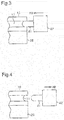
- Figs. 3 and 4 show the operation of the contact mechanism 40.
- a constant pressure processing can be performed.
- a constant dimension processing (constant dimension cutting) is more preferable.
- the constant pressure processing which is mainly used to improve surface roughness
- the tool 41 is pressed against the polishing surface 11 at a constant pressing force when polishing.
- the constant dimension processing which is mainly used to finish the shape
- the tool 41 is cut into the polishing surface 11 by a constant dimension.
- the constant dimension processing which is suitable for the shape finishing, is suitable when modifying or processing the shape of the polishing surface 11 with the tool 41.
- the shape may be further accurately modified or processed compared to the constant pressure processing.
- the constant pressure processing may be performed when modifying or processing the shape of the polishing surface 11 with the tool 41.
- the processing may be performed, for example, to improve the accuracy of the surface roughness of the workpiece K, and is suitable mainly when the tool 41 is the surface modifying tool and modifies the polishing surface 11.
- the tool 41 is normally located in a position separated from the polishing surface 11 as shown in Fig. 4 . While the polishing member 10 is driven to be rotated, the tool 41 is moved to the position shown in Fig. 3 , where the tool 41 contacts the polishing surface 11, in each predetermined cycle, for example, when an accumulated value of polishing time exceeds a predetermined value or when the operator operates a switch.
- water or the processing liquid be supplied to the contact portion of the tool 41 and the polishing surface 11. This helps the processing or modification of the polishing surface 11 performed by the tool 41 and cools the contact portion.
- any appropriate kind of the used processing liquid may be selected in accordance with the kind of the shape-processing cutting tool or the surface modifying tool or the material of the polishing member.
- a processing liquid for cutting may be applied.
- a processing liquid for grinding may be applied.
- a cleaning liquid may be applied.
- the present embodiment has the advantages described below.
- the polishing surface 11 of the polishing member 10 is shaped in conformance with the shape of the end KE of the workpiece K.
- the shape of the polishing surface 11 and the shape of the tool 41 have the relationship in which one is concave and the other is convex. This allows the shape processing or shape modification to be easily performed on the polishing surface 11 that is non-planar, or curved.
- the abrasive grains may fall off when grinding the polishing surface 11 of the polishing member 10. This may damage the surface of the workpiece K.
- the surface of the electrodeposition whetstone may be coated with a hard layer, for example, diamond-like carbon (DLC). This limits fall-off of the abrasive grains and damages such as that describe above.
- DLC diamond-like carbon
- Fig. 5 shows the schematic structure of this modified example of the polishing device.
- a contact mechanism 60 is located at a position that is proximate to the radially outer circumference surface of the polishing member 10 and opposed to the polishing surface 11.
- the contact mechanism 60 includes a cutter 50 such as that described above and a moving mechanism that reciprocates a rotation axis of the cutter 50 in directions (directions of arrows M shown in Fig. 5 ) orthogonal to the rotation axis of the polishing member 10.
- the contact mechanism 60 moves the cutter 50 toward the rotation center of the polishing member 10 (in direction of arrow M1), the blade of the cutter 50 contacts the polishing surface 11 as indicated by the double-dashed line shown in Fig. 5 .
- the contact mechanism 60 moves the cutter 50 in a direction separated away from the rotation center of the polishing member 10 (in direction of arrow M2), the blade of the cutter 50 is separated from the polishing surface 11.
- the shape of the polishing surface 11 and the shape of the blade of the cutter 50 also have the relationship in which one is concave and the other is convex. This allows for the easy shape modification of the polishing surface 11 that is non-planar, or curved.
- Fig. 6 shows a tubular shape-processing cutting tool 200 including a plurality of cutting blades 210 that axially extend and are circumferentially arranged at intervals.
- the shape-processing cutting tool 200 includes a distal portion 210a in which the external shape of the cutting blades 210 has the same curvature as the end KE.
- the distal portion 210a comes in contact with the polishing surface 11 as the shape-processing cutting tool 200 rotates. This processes the polishing surface 11 of the polishing member 10 to be shaped in conformance with the shape of the end KE.
- Figs. 7(A) and 7(B) show a flat shape-processing cutting tool 300 that includes a round cutting blade having the same curvature as the end KE defining a distal portion 310.
- the shape-processing cutting tool 300 is thinned toward the distal portion 310.
- the distal portion 310 comes in contact with the polishing surface 11 as the shape-processing cutting tool 300 rotates. This processes the polishing surface 11 of the polishing member 10 to be shaped in conformance with the shape of the end KE.
- a plurality of flat shape-processing cutting tools 300 may be combined.
- the flat shape-processing cutting tools 300 may be combined so that the flat shape-processing cutting tools 300 intersect with one another at a predetermined angle, such as 60° or 90°.
- Fig. 8 shows a tubular surface modifying tool 400 including a distal hard brush 410.
- the distal shape of the brush 410 is semispherical as a whole.
- the semispherical shape has substantially the same curvature as the end KE.
- the brush 410 comes in contact with the polishing surface 11 as the surface modifying tool 400 rotates. This modifies the polishing surface 11 of the polishing member 10 to be shaped in conformance with the shape of the end KE.
- the polishing member 10A having a flat radially outer circumferential surface is fixed to the base 20.
- the contact mechanism 40 moves the holder 42 toward the rotation center of the polishing member 10A (in direction of arrow M1), the tool 41 contacts the radially outer circumferential surface of the polishing member 10A. More specifically, the tool 41 is pressed against the radially outer circumferential surface of the polishing member 10A. The pressing of the tool 41 forms the polishing surface 11 in the flat outer circumferential surface of the polishing member 10A.
- the contact mechanism 40 moves the holder 42 in a direction separated away from the rotation center of the polishing member 10A (in direction of arrow M2) to separate the tool 41 away from the polishing surface 11.
- forming the polishing surface 11 to be shaped in conformance with the shape of the end KE of the workpiece K is performed in the polishing device.
- the shape of the polishing surface 11 may be formed with high accuracy compared to when the polishing member 10 including the polishing surface 11 that is formed in advance in conformance with the shape of the end KE of the workpiece K is coupled to the polishing device. This eliminates the task for preparing the polishing member 10 that includes the polishing surface 11 in advance.
- the rod 70 is wound around a disk 80 so that the polishing surface 71 is opposed outward, and the wound rod 70 is fixed to the disk 80 in an appropriate manner.
- a polishing member that is similar to the polishing member 10 is also formed through such a manner.
- Any material may be selected for the disk 80.
- a metal or ceramic may be used. However, the material is preferred to be as light as possible.
- the rod 70 is wound around the disk 80.
- the polishing surface 71 may be formed in the rod 70.
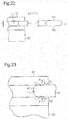
- the polishing member 10 is formed from a material such as a resin that has elasticity to a certain extent and elastically deforms. Then, as shown in Fig. 22 , the width H1 of the polishing surface 11 in a direction parallel to the rotation axis of the polishing member 10 (direction of arrow Y in Fig. 22 ) is set less than the thickness T1 of the workpiece K prior to the processing (i.e., length between upper surface KU and lower surface KD of workpiece K) by a predetermined amount ⁇ .
- the polishing member 10 is formed by an elastic body and the polishing surface 11 is smaller in shape than the workpiece K to be polished, has the advantages described below.
- the workpiece K may be appropriately processed.
- 10, 10A, 90 polishing member; 11: polishing surface; 20: base; 21: first motor; 30: second motor; 31: rotation shaft; 32: fixing seat; 33: motor moving mechanism; 40: contact mechanism; 41: tool; 42: holder; 43: moving mechanism; 50: cutter; 60: contact mechanism; 70: rod; 71: polishing surface; 80: disk; 91: curved surface; 100: non-woven fabric; 200: shape-processing cutting tool; 210: cutting blade; 210a: distal portion; 300: shape-processing cutting tool; 310: distal portion; 400: surface modifying tool; 410: brush; K: workpiece to be polished; KE: end (of workpiece); KU: upper surface (of workpiece); KD: lower surface (of workpiece).
Landscapes
- Engineering & Computer Science (AREA)
- Mechanical Engineering (AREA)
- Chemical & Material Sciences (AREA)
- Ceramic Engineering (AREA)
- Inorganic Chemistry (AREA)
- Finish Polishing, Edge Sharpening, And Grinding By Specific Grinding Devices (AREA)
- Grinding And Polishing Of Tertiary Curved Surfaces And Surfaces With Complex Shapes (AREA)
- Grinding-Machine Dressing And Accessory Apparatuses (AREA)
- Polishing Bodies And Polishing Tools (AREA)
Abstract
Description
- The present invention relates to a polishing device, a method for processing a polishing member, a method for modifying the polishing member, a shape-processing cutting tool, and a surface modifying tool.
-
Patent document 1 describes that when a portion to be polished of a workpiece (object to be polished) is polished with a polishing member, the shape of a polishing surface of the polishing member gradually changes. Generally, dressing is performed to modify the polishing surface and return it to its original shape. - Patent Document 1: Japanese Laid-Open Patent Publication No.
11-188590 - In the prior art, dressing is often performed to modify a planar polishing surface. Little consideration is made to the dressing of polishing surfaces having various shapes in conformance with the shapes of portions to be polished of workpieces.
- The present invention is made in view of such circumstances, and its objective is to provide a polishing device, a method for processing a polishing member, and a method for modifying the polishing member that allow shape processing and shape modification to be easily performed on a polishing surface having a non-planar shape. Also, it is an object of the present invention to provide a shape-processing cutting tool used in the polishing device or the processing method to process the shape of the polishing surface or a surface modifying tool used in the polishing device or the modification method to modify the polishing surface to be shaped in conformance with the shape of a portion to be polished.
- To solve the above problem, a polishing device includes a polishing member, a shape-processing cutting tool or a surface modifying tool, and a contact mechanism. The polishing member includes a polishing surface that is shaped in conformance with the shape of a portion to be polished of a workpiece. The shape-processing tool has the same shape as the portion to be polished and processes the polishing surface to be shaped in conformance with the shape of the portion to be polished. The surface modifying tool has the same shape as the portion to be polished and modifies the polishing surface to be shaped in conformance with the shape of the portion to be polished. The contact mechanism brings the shape-processing cutting tool or the surface modifying tool into contact with the polishing surface.
- In this configuration, the polishing member includes a polishing surface that is shaped in conformance with the shape of a portion to be polished of a workpiece. Thus, the portion to be polished of the workpiece can be polished even when having a non-planar shape, for example, a curved surface or a triangular shape.
- In this configuration, the contact mechanism brings a shape-processing cutting tool or a surface modifying tool into contact with the polishing surface. The shape-processing cutting tool has the same shape as the portion to be polished and processes the polishing surface to be shaped in conformance with the shape of the portion to be polished. The surface modifying tool has the same shape as the portion to be polished and modifies the polishing surface to be shaped in conformance with the shape of the portion to be polished. Thus, the polishing surface, which is in contact with the shape-processing cutting tool or the surface modifying tool, copies the shape of the shape-processing cutting tool or the surface modifying tool that has the same shape as the portion to be polished of the workpiece. This processes or modifies the polishing surface to be shaped in conformance with the shape of the portion to be polished of the workpiece. Although the polishing surface of the polishing member is shaped in conformance with the shape of the portion to be polished of the workpiece, the shape of the polishing surface and the shape of each of the shape-processing cutting tool and the surface modifying tool have the relationship in which one is concave and the other is convex. This allows the shape of the polishing surface having a non-planar shape to be easily processed or modified.
- The portion to be polished of the workpiece and the shape-processing cutting tool or the surface modifying tool do not need to have exactly the same shape as each other and may have slightly different shapes from each other as long as no practical problem occurs.
- The shape-processing cutting tool is configured to process the polishing surface of the polishing member and is not particularly limited as long as it includes a processing portion having higher hardness than the polishing surface of the polishing member. Specific examples include a processing tool including fixed abrasive grains, such as pellets or an electrode position whetstone, and a cutting tool, such as an end mill or a bit.
- The surface modifying tool is configured to adjust the surface of the polishing member and to remove grime or deposition from the surface of the polishing member. Specific examples include a processing tool including fixed abrasive grains and a hard brush.
- In the polishing device, the contact mechanism brings the shape-processing cutting tool or the surface modifying tool into contact with the polishing surface preferably in predetermined cycles. In this configuration, the polishing surface is processed or modified in each predetermined cycle. This appropriately maintains the accuracy for polishing the workpiece.
- In the polishing device, it is preferable that through a process of bringing a surface of the polishing member that differs in shape from the portion to be polished into contact with the shape-processing cutting tool or the surface modifying tool, the polishing surface of the polishing member be formed to be shaped in conformance with the shape of the portion to be polished.
- In this configuration, forming the polishing surface to be shaped in conformance with the shape of the portion to be polished of the workpiece is performed in the polishing device. Thus, the shape of the polishing surface may be formed with high accuracy compared to when the polishing member including the polishing surface that is formed in advance in conformance with the shape of the portion to be polished of the workpiece is coupled to the polishing device.
- The polishing device preferably includes a motor that rotates the polishing member from below. The polishing device preferably includes a base including an upper surface. When the polishing member is located on the upper surface, the base is rotated integrally with the polishing member. These configurations obtain stable rotation of the polishing member with a small axial run-out and allows for polishing to be performed with higher accuracy.
- When the polishing device includes a shape-processing cutting tool that has the same shape as the portion to be polished and processes the polishing surface to be shaped in conformance with the shape of the portion to be polished or a surface modifying tool that has the same shape as the portion to be polished and modifies the polishing surface to be shaped in conformance with the shape of the portion to be polished, the shape of the polishing surface having a non-planar shape can be easily processed or modified.
- To solve the above problem, a method for processing or modifying a polishing member includes bringing a shape-processing cutting tool or a surface modifying tool into contact with a polishing surface of the polishing member. The polishing surface is shaped in conformance with the shape of a portion to be polished of a workpiece. The shape-processing cutting tool has the same shape as the portion to be polished and processes the polishing surface to be shaped in conformance with the shape of the portion to be polished. The surface modifying tool has the same shape as the portion to be polished and modifies the polishing surface to be shaped in conformance with the shape of the portion to be polished.
- In this method, the polishing member is prepared that includes a polishing surface shaped in conformance with the shape of a portion to be polished of a workpiece. Thus, the portion to be polished of the workpiece can be polished even when having a non-planar shape, for example, a curved surface or a triangular shape.
- In this method, the shape-processing cutting tool, which has the same shape as the portion to be polished and processes the polishing surface to be shaped in conformance with the shape of the portion to be polished, or the surface modifying tool, which has the same shape as the portion to be polished and modifies the polishing surface to be shaped in conformance with the portion to be polished, is brought into contact with the polishing surface. Thus, the polishing surface, which is in contact with the shape-processing cutting tool or the surface modifying tool, copies the shape of the shape-processing cutting tool or the surface modifying tool that has the same shape as the portion to be polished of the workpiece. This modifies the polishing surface to be shaped in conformance with the shape of the portion to be polished of the workpiece. Although the polishing surface of the polishing member is shaped in conformance with the shape of the portion to be polished of the workpiece, the shape of the polishing surface and the shape of each of the shape-processing cutting tool and the surface modifying tool have the relationship in which one is concave and the other is convex. This allows the shape of the polishing surface having a non-planar shape to be easily modified.
- The present invention succeeds in facilitating shape processing or shape modification of a polishing surface having a non-planar shape.
-
-
Fig. 1 is a schematic plan view showing the structure of a polishing device according to one embodiment. -
Fig. 2 is a schematic side view showing the structure of the polishing device of the embodiment. -
Fig. 3 is a partial side view showing the polishing device of the embodiment when a shape-processing cutting tool or a surface modifying tool is in contact with a polishing member. -
Fig. 4 is a partial side view showing the polishing device of the embodiment when the shape-processing cutting tool or the surface modifying tool is separated from the polishing member. -
Fig. 5 is a schematic plan view showing the structure of a polishing device according to a modified example of the embodiment. -
Fig. 6 is a side view showing the structure of a shape-processing cutting tool according to another modified example of the embodiment. -
Fig. 7(A) is a side view showing the structure of a shape-processing cutting tool according to another modified example of the embodiment. -
Fig. 7(B) is a cross-sectional view taken along line C-C. -
Fig. 8 is a side view showing the structure of a surface modifying tool according to another modified example of the embodiment. -
Fig. 9 is a side view showing the operation of a contact mechanism according to another modified example of the embodiment. -
Fig. 10 is a side view showing the operation of the contact mechanism according to the modified example shown inFig. 9 . -
Fig. 11 is a side view showing the operation of the contact mechanism according to the modified example shown inFig. 9 . -
Fig. 12 is a perspective view showing a rod according to another modified example of the embodiment. -
Fig. 13 is a plan view showing a polishing member according to the modified example shown inFig. 12 . -
Fig. 14 is a side view showing a polishing member according to another modified example of the embodiment. -
Fig. 15 is a plan view showing the polishing member according to the modified example shown inFig. 14 . -
Fig. 16 is a side cross-sectional view showing the polishing member according to the modified example shown inFig. 14 . -
Fig. 17 is a partial side view showing a workpiece and a polishing member according to another modified example of the embodiment. -
Fig. 18 is a partial side view showing a workpiece and a polishing member according to another modified example of the embodiment. -
Fig. 19 is a partial side view showing a workpiece and a polishing member according to another modified example of the embodiment. -
Fig. 20 is a partial side view showing a workpiece and a polishing member according to another modified example of the embodiment. -
Fig. 21 is a partial side view showing a workpiece and a polishing member according to another modified example of the embodiment. -
Fig. 22 is a partial side view showing a polishing member according to another modified example of the embodiment. -
Fig. 23 is a partial side view showing the polishing member according to the modified example shown inFig. 22 . - A polishing device, a method for modifying a polishing member, a shape-processing cutting tool, and a surface modifying tool according to one embodiment of the present invention will now be described with reference to
Figs. 1 to 4 . - As shown in
Fig. 1 , the polishing device includes a discoid polishingmember 10. The polishingmember 10 includes a radially outer circumferential surface that is used to polish an end KE of a workpiece K, which is a portion to be polished. The end KE is machined in advance to have a curved surface. The workpiece K may have any shape, for example, in accordance with its application. - Any optimal material for polishing the end KE may be used for the polishing
member 10. For example, when a resin is used as the material of the polishingmember 10, any synthetic resin may be used. Examples of such a synthetic resin include a thermosetting resin (phenol resin, epoxy resin, urethane resin, polyimide, etc.) and a thermoplastic resin (polyethylene, polypropylene, acrylic resin, polyamide, polycarbonate, etc.). Alternatively, a cloth, a non-woven fabric, a resin processed non-woven fabric, synthetic leather, or a composite thereof may be used. The polishing surface of the polishingmember 10 preferably has a Shore A hardness of 5 or greater. When a polishingmember 10 having a shore A hardness of 5 or greater, which is subject to hardness measurement, is left for 60 minutes or longer in a dry condition where the humidity is 20% to 60% under room temperature, the hardness of the polishing surface of the polishing member is then measured with a durometer (type A) that is compliance with JIS K6253, and the measured value is 5 or greater. When the Shore A hardness is 5 or greater, the surface of the workpiece K can be polished in a preferred manner. Further, deformation of the polishing surface of the polishingmember 10 can be reduced that would be caused by polishing performed within a short period of time. - The Shore A hardness of the polishing surface of the polishing
member 10 is preferably 40 or greater, more preferably 70 to 95, and particularly preferably 70 to 85. - When a metal is used as the material of the polishing
member 10, magnesium, aluminum, titanium, iron, nickel, cobalt copper, zinc, manganese, or an alloy of which the main component is any of these metals may be used. - When a resin or a metal is used as the material of the polishing
member 10, the polishingmember 10 may include abrasive grains. The kind of the used abrasive grains is not particularly limited and may be metal oxide particles of silicon oxide, aluminum oxide, zirconium oxide, cerium oxide, magnesium oxide, calcium oxide, titanium oxide, manganese oxide, iron oxide, or chromium oxide; a carbide, such as silicon carbide; a nitride; a boride; or a diamond. - When a ceramic is used as the material of the polishing
member 10, any of ceramics and glass; any of an oxide, nitride, boride, and carbide of silicon, aluminum, zirconium, calcium, and barium; or any of aluminum oxide, zirconium oxide, silicon oxide, silicon carbide, silicon nitride, and boron nitride may be used. - Further, any material may be used for the workpiece K. For example, when a resin is used as the material of the workpiece K, any synthetic resin may be used. Examples of such a synthetic resin include a thermosetting resin (phenol resin, epoxy resin, urethane resin, polyimide, etc.) and a thermoplastic resin (polyethylene, polypropylene, acrylic resin, polyamide, polycarbonate, etc.).
- When a ceramic is used as the material of the workpiece K, any of ceramics, glass, and fine ceramics; any of an oxide, carbide, nitride, and boride of silicon, aluminum, zirconium, calcium, and barium may be used.
- When a metal is used as the material of the workpiece K, magnesium, aluminum, titanium, iron, nickel, cobalt, copper, zinc, manganese, or an alloy of which the main component is any of these metals may be used.
- The workpiece K may be used for any purpose. For example, the workpiece K may be used as a wheel, a shaft, a container, a casing (for example, case and housing), a frame, a ball, a wire, an ornament, or the like.
- As shown in
Fig. 2 , the polishingmember 10 is fixed to the upper surface of adiscoid base 20 in a removable manner. The lower surface of thebase 20 includes a center portion that is fixed to a rotation shaft of afirst motor 21. When thefirst motor 21 is driven to be rotated, thebase 20 and the polishingmember 10 rotate. Thefirst motor 21 is located below the polishingmember 10 and thebase 20. The polishingmember 10, which is located on the upper surface of thebase 20, is rotated together with the base 20 from below. This obtains stable rotation of the polishingmember 10 with a small axial run-out and allows for polishing to be performed with higher accuracy. - The radially outer circumferential surface of the polishing
member 10 includes a polishingsurface 11, which is a curved grooved surface that circumferentially extends. The curvature of the polishingsurface 11 is shaped in conformance with the shape of the end KE of the workpiece K (shape of portion to be polished). More specifically, the polishingsurface 11 and the end KE have the same curvature. - The workpiece K is held by a fixing
seat 32 in a removable manner. The fixingseat 32 is fixed to arotation shaft 31 of asecond motor 30. Thesecond motor 30 is coupled to amotor moving mechanism 33 that reciprocates thesecond motor 30 in directions orthogonal to a rotation axis of the polishing member 10 (directions of arrows X shown inFigs. 1 and 2 ). When themotor moving mechanism 33 moves thesecond motor 30, thesecond motor 30, therotation shaft 31, the fixingseat 32, and the workpiece K are integrally move in the directions orthogonal to the rotation axis of the polishingmember 10. Such movement of thesecond motor 30 caused by themotor moving mechanism 33 presses the end KE of the workpiece K against the polishingsurface 11. Then, a contact portion of the end KE and the polishingsurface 11 is appropriately supplied with, for example, a processing liquid, and each of thefirst motor 21 and thesecond motor 30 is driven at a predetermined rotation speed. This polishes the end KE having the curved surface. When pressing the end KE of the workpiece K against the polishingsurface 11, the pressing force is adjusted so that predetermined pressure is applied. - The processing liquid may be directly supplied to the contact portion of the end KE and the polishing
surface 11 from the outer side. Alternatively, a processing liquid supply mechanism such as a rotary joint may be arranged in a portion that connects the polishingmember 10 and thefirst motor 21. When the processing liquid supply mechanism supplies the processing liquid into the polishingmember 10, the processing liquid may be supplied from the polishingmember 10 to the contact portion through a supply passage formed in the polishingmember 10. When supplied from the inside of the polishingmember 10 toward the contact portion, the processing liquid may be further efficiently supplied. Additionally, to efficiently use the processing liquid, it is further preferable that a cover be arranged around the polishingmember 10 and that a collection device be provided to increase the efficiency for collecting the processing liquid. - A suitable kind of the processing liquid may be used in accordance with the material of the workpiece K to be polished and the polishing
member 10. Specifically, a cutting liquid, grinding liquid, a lapping material, a polishing agent, or a chemical mechanical polishing liquid may be used. The processing liquid may include abrasive grains. The kind of the used abrasive grains is not particularly limited and may be metal oxide particles of silicon oxide, aluminum oxide, zirconium oxide, cerium oxide, magnesium oxide, calcium oxide, titanium oxide, manganese oxide, iron oxide, or chromium oxide; a carbide, such as silicon carbide; a nitride; a boride; or a diamond. - For example, the amount of the abrasive grains contained in the processing liquid is preferably 1 mass percent or greater, and more preferably 2 mass percent or greater. The amount of the abrasive grains contained in the processing liquid is also preferably 50 mass percent or less, and more preferably 40 mass percent or less.
- The abrasive grains in the processing liquid have an average secondary particle diameter of preferably 0.1 µm or greater, and more preferably 0.3 µm or greater. As the average secondary particle diameter of the abrasive grains increases, the processing liquid improves the processing speed.
- Additionally, the average secondary particle diameter of the abrasive grains in the processing liquid is preferably 20 µm or less, and more preferably 5 µm or less. As the average secondary particle diameter of the abrasive grains decreases in the processing liquid, the surface of the workpiece K can be further evenly polished. The average secondary particle diameter of the abrasive grains is a volume average particle diameter that is measured with a laser diffraction/scattering particle size distribution measurement instrument, such as "LA-950" manufactured by HORIBA, Ltd.
- When necessary, the processing liquid may include another component such as a pH adjuster, an etching agent, an oxidant, a water-soluble polymer, a copolymer and a salt and derivative thereof, an anticorrosive, a chelating agent, a dispersant aid, an antiseptic, or a fungicide
- For example, a known acid, base, or a salt of them may be used as the pH adjuster. Examples of such an acid that can be used as the pH adjuster include an inorganic acid, such as hydrochloric acid, sulfuric acid, nitric acid, hydrofluoric acid, boric acid, carbonic acid, hypophosphorous acid, phosphorous acid, or phosphoric acid; and an organic acid, such as formic acid, acetic acid, propionic acid, butyric acid, valeric acid, 2-methylbutyricacid, n-hexanoic acid, 3,3-dimethylbutyric acid, 2-ethylbutyric acid, 4-methylpentanoic acid, n-heptanoic acid, 2-methylhexanoic acid, n-octanoic acid, 2-ethylhexanoic acid, benzoic acid, glycolic acid, salicylic acid, glyceric acid, oxalic acid, malonic acid, succinic acid, glutaric acid, adipic acid, pimelic acid, maleic acid, phthalic acid, malic acid, tartaric acid, citric acid, lactic acid, diglycolic acid, 2-furancarboxylic acid, 2,5-furandicarboxylic acid, 3-furancarboxylic acid, 2-tetrahydrofurancarboxylic acid, methoxyacetic acid, methoxyphenylacetic acid, or phenoxyacetic acid.
- Examples of such a base that can be used as the pH adjuster include an amine, such as aliphatic amine or aromatic amine; an organic base, such as quaternary ammonium hydroxide; an alkali metal hydroxide, such as potassium hydroxide; an alkaline earth metal hydroxide; and ammonia.
- Instead of the above acid or in combination with the above acid, a salt of the above acid, such as an ammonium salt or an alkali metal salt, may be used as the pH adjuster. Such a pH adjuster is used to adjust the pH value of the processing liquid to the optimal value, which differs in accordance with the kind of the workpiece K to be polished.
- Examples of the etching agent include an inorganic acid, such as nitric acid, sulfuric acid, or phosphoric acid; an organic acid, such as acetic acid, citric acid, tartaric acid, or methanesulfonic acid; an inorganic alkali, such as potassium hydroxide or sodium hydroxide; and an organic alkali, such as ammonia, amine, or quaternary ammonium hydroxide.
- Examples of the oxidant include hydrogen peroxide, peracetic acid, a percarbonate, urea peroxide, a perchlorate, a persulfate, an oxoacid, such as sulfuric acid, nitric acid, or phosphoric acid, and a salt of the oxoacid.
- Examples of the water-soluble polymer, the copolymer and the salt and derivative thereof include a polycarboxylic acid, such as a polyacrylate; a polysulfonic acid, such as polyphosphonic acid or polystyrenesulfonic acid; a polysaccharide, such as xanthan gum or sodium alginate; a cellulose derivative, such as hydroxyethyl cellulose or carboxymethyl cellulose; polyethylene glycol; polyvinyl alcohol; polyvinylpyrrolidone; sorbitan monooleate; an oxyalkylene-based polymer having one or more kinds of oxyalkylene unit; a non-ionic surfactant; and an anionic surfactant. Examples of the non-ionic surfactant include polyoxyethylene alkylether, polyoxyethylene alkylphenylether, sorbitan monooleate, and an oxyalkylene-based polymer having one or more kinds of oxyalkylene unit. Examples of the anionic surfactant include an alkylsulfonic acid-based compound, an alkylbenzenesulfonic acid-based compound, an alkylnaphthalenesulfonic acid-based compound, a methyltaurine acid-based compound, an alkyldiphenyletherdisulfonic acid-based compound, an α-olefinsulfonic acid-based compound, a naphthalenesulfonic acid condensate, and a sulfosuccinic acid diester-based compound.
- Examples of the anticorrosive include a monocyclic compound, a polycyclic compound having a condensed ring, and heterocyclic compound, such as an amine, a pyridine, a tetraphenylphosphonium salt, a benzotriazole, a triazole, a tetrazole, or benzoic acid.
- Examples of the chelating agent include a carboxylic acid-based chelating agent, such as gluconic acid; an amine-based chelating agent, such as ethylenediamine, diethylenetriamine, or trimethyltetraamine; polyaminopolycarbon-based chelating agent, such as ethylenediaminetetraacetic acid, nitrilotriacetic acid, hydroxyethylethylenediaminetriacetic acid, triethylenetetraminehexaacetic acid, or diethylenetriaminepentaacetic acid; an organic phosphonic acid-based chelating agent, such as 2-aminoethylphosphonic acid, 1-hydroxyethylidene-1,1-diphosphonic acid, aminotri(methylenephosphonic acid), ethylenediaminetetrakis(methylenephosphonic acid), diethylenetriaminepenta(methylenephosphonic acid), ethane-1,1-diphosphonic acid, ethane-1,1,2-triphosphonic acid, methanehydroxyphosphonic acid, or 1-phosphonobutan-2,3,4-tricarboxylic acid; a phenol derivative; and 1,3-diketone.
- Examples of the dispersant aid include a condensed phosphate, such as pyrophosphate or hexametaphosphate.
- Examples of the antiseptic include sodium hypochlorite.
- Examples of the fungicide include an oxazoline, such as oxazolidine-2,5-dione.
- When the diameter of the polishing
member 10 is maximized within a range in which the polishing accuracy is appropriately maintained, ends KE of workpieces K may be simultaneously polished with the circumferential surface of the polishingmember 10. This improves the productivity. Additionally, the maximum diameter of the polishingmember 10 increases the linear velocity of the polishingmember 10 at the outer circumference even when the rotation speed of the polishingmember 10 is the same. This obtains the sufficient linear velocity for the polishing even when the rotation speed of the polishingmember 10 is relatively decreased. Thus, for example, dispersion of the processing liquid may be reduced. - As shown in
Fig. 1 , acontact mechanism 40 is located at a position that is proximate to the radially outer circumferential surface of the polishingmember 10 and opposed to the polishingsurface 11. - The
contact mechanism 40 includes atool 41. Thetool 41 is rod-shaped and includes a distal processing portion. The processing portion is shaped in conformance with the shape of the end KE and, more specifically, has the same curvature as the end KE. Thetool 41 functions as a shape-processing cutting tool that processes the polishingsurface 11 to be shaped in conformance with the shape of the end KE or a surface modifying tool that modifies the polishingsurface 11 to be shaped in conformance with the shape of the end KE. An optimal material for processing or modifying the polishingsurface 11 is selected for thetool 41. The end KE of the workpiece K to be polished and thetool 41 do not need to have exactly the same shape as each other and may have slightly different shapes from each other as long as no practical problem occurs. - The
contact mechanism 40 also includes aholder 42, to which thetool 41 is fixed in a removable manner, and a movingmechanism 43 that reciprocates theholder 42 in directions (directions of arrows M shown inFig. 1 ) orthogonal to the rotation axis of the polishingmember 10. The drive source of the movingmechanism 43 may be electric power or hydraulic pressure. The movingmechanism 43 may be automatically driven by a controller including, for example, a CPU, a RAM, and a ROM or may be driven, for example, when the operator of the polishing device operates a switch. -
Figs. 3 and 4 show the operation of thecontact mechanism 40. - As shown in
Fig. 3 , when thecontact mechanism 40 moves theholder 42 toward the rotation center of the polishing member 10 (in direction of arrow M1), thetool 41 contacts the polishingsurface 11. More specifically, thetool 41 is pressed against the polishingsurface 11. - When pressing the
tool 41 against the polishingsurface 11, a constant pressure processing can be performed. However, a constant dimension processing (constant dimension cutting) is more preferable. In the constant pressure processing, which is mainly used to improve surface roughness, thetool 41 is pressed against the polishingsurface 11 at a constant pressing force when polishing. In the constant dimension processing, which is mainly used to finish the shape, thetool 41 is cut into the polishingsurface 11 by a constant dimension. The constant dimension processing, which is suitable for the shape finishing, is suitable when modifying or processing the shape of the polishingsurface 11 with thetool 41. Thus, the shape may be further accurately modified or processed compared to the constant pressure processing. - The constant pressure processing may be performed when modifying or processing the shape of the polishing
surface 11 with thetool 41. In this case, the processing may be performed, for example, to improve the accuracy of the surface roughness of the workpiece K, and is suitable mainly when thetool 41 is the surface modifying tool and modifies the polishingsurface 11. - As shown in
Fig. 4 , when thecontact mechanism 40 moves theholder 42 in a direction (direction of arrow M2) separated away from the rotation center of the polishingmember 10, thetool 41 is separated away from the polishingsurface 11. - The
tool 41 is normally located in a position separated from the polishingsurface 11 as shown inFig. 4 . While the polishingmember 10 is driven to be rotated, thetool 41 is moved to the position shown inFig. 3 , where thetool 41 contacts the polishingsurface 11, in each predetermined cycle, for example, when an accumulated value of polishing time exceeds a predetermined value or when the operator operates a switch. - When the
tool 41 is in contact with the polishingsurface 11, it is preferred that water or the processing liquid be supplied to the contact portion of thetool 41 and the polishingsurface 11. This helps the processing or modification of the polishingsurface 11 performed by thetool 41 and cools the contact portion. - Any appropriate kind of the used processing liquid may be selected in accordance with the kind of the shape-processing cutting tool or the surface modifying tool or the material of the polishing member. For example, when a cutting tool is used, a processing liquid for cutting may be applied. When a processing tool including fixed abrasive grains is used, a processing liquid for grinding may be applied. When a hard brush is used, for example, a cleaning liquid may be applied.
- The present embodiment has the advantages described below.
- (1) The polishing device includes a polishing
member 10 having a polishingsurface 11 shaped in conformance with the shape of an end KE of a workpiece K to be polished. Thus, even when the end KE of the workpiece K has a non-planar surface, or a curved surface, the end KE can be polished. - (2) The polishing device includes a
tool 41 and acontact mechanism 40. Thetool 41, which has the same shape as the end KE, modifies or processes the polishingsurface 11 to be shaped in conformance with the shape of the end KE. Thecontact mechanism 40 brings thetool 41 into contact with the polishingsurface 11. Thus, as shown inFig. 3 , when in contact with thetool 41, the polishingsurface 11 copies the shape of thetool 41, which has the same curvature as the shape of the end KE of the workpiece K. This modifies or processes the polishingsurface 11 to be shaped in conformance with the shape of the end KE of the workpiece K. - The polishing
surface 11 of the polishingmember 10 is shaped in conformance with the shape of the end KE of the workpiece K. However, the shape of the polishingsurface 11 and the shape of thetool 41 have the relationship in which one is concave and the other is convex. This allows the shape processing or shape modification to be easily performed on the polishingsurface 11 that is non-planar, or curved. - (3) The
contact mechanism 40 brings thetool 41 into contact with the polishingsurface 11 in each predetermined cycle. Thus, the polishingsurface 11 is modified in each predetermined cycle. This maintains the accuracy for polishing the end KE of the workpiece K for a long time. - The above embodiment may be modified as follows.
- The
tool 41 may modify the polishingsurface 11 during an interval between the polishing of the workpiece K. Alternatively, thetool 41 may modify the polishingsurface 11 at the same time as when polishing the workpiece K for the entire time or a partial time of polishing. - The shape-processing cutting tool is configured to process the polishing surface of the polishing member and is not particularly limited as long as it includes a processing portion having higher hardness than the polishing surface of the polishing member. Specific examples include a processing tool including fixed abrasive grains, such as pellets or an electrodeposition whetstones, and a cutting tool, such as an end mill or a bit.
- When the electrodeposition whetstone is used, the abrasive grains may fall off when grinding the polishing
surface 11 of the polishingmember 10. This may damage the surface of the workpiece K. One needs to pay attention to such damages particularly when grinding the polishingsurface 11 with the electrodeposition whetstone during the polishing of the workpiece K with the polishingmember 10. In this regard, the surface of the electrodeposition whetstone may be coated with a hard layer, for example, diamond-like carbon (DLC). This limits fall-off of the abrasive grains and damages such as that describe above. - The surface modifying tool is configured to adjust the surface of the polishing member and to remove grime or deposition from the surface of the polishing member. Specific examples include a processing tool including fixed abrasive grains and a hard brush.
- As shown in
Fig. 5 , a rotary cutter may be used as thetool 41, which functions as the shape-processing cutting tool or the surface modifying tool. The rotary cutter includes an outer circumferential blade that has the same shape as the end KE of the workpiece K to be polished and modifies the polishingsurface 11 to be shaped in conformance with the shape of the end KE. -
Fig. 5 shows the schematic structure of this modified example of the polishing device. As shown inFig. 5 , acontact mechanism 60 is located at a position that is proximate to the radially outer circumference surface of the polishingmember 10 and opposed to the polishingsurface 11. Thecontact mechanism 60 includes acutter 50 such as that described above and a moving mechanism that reciprocates a rotation axis of thecutter 50 in directions (directions of arrows M shown inFig. 5 ) orthogonal to the rotation axis of the polishingmember 10. When thecontact mechanism 60 moves thecutter 50 toward the rotation center of the polishing member 10 (in direction of arrow M1), the blade of thecutter 50 contacts the polishingsurface 11 as indicated by the double-dashed line shown inFig. 5 . When thecontact mechanism 60 moves thecutter 50 in a direction separated away from the rotation center of the polishing member 10 (in direction of arrow M2), the blade of thecutter 50 is separated from the polishingsurface 11. In this modified example, the shape of the polishingsurface 11 and the shape of the blade of thecutter 50 also have the relationship in which one is concave and the other is convex. This allows for the easy shape modification of the polishingsurface 11 that is non-planar, or curved. - A tool other than the
tool 41 may be used as the tool functioning as the shape-processing cutting tool or the surface modifying tool. Such modified examples will now be described below. -
Fig. 6 shows a tubular shape-processing cutting tool 200 including a plurality of cuttingblades 210 that axially extend and are circumferentially arranged at intervals. The shape-processing cutting tool 200 includes adistal portion 210a in which the external shape of thecutting blades 210 has the same curvature as the end KE. When the shape-processing cutting tool 200 is used instead of thetool 41, thedistal portion 210a comes in contact with the polishingsurface 11 as the shape-processing cutting tool 200 rotates. This processes the polishingsurface 11 of the polishingmember 10 to be shaped in conformance with the shape of the end KE. -
Figs. 7(A) and 7(B) show a flat shape-processing cutting tool 300 that includes a round cutting blade having the same curvature as the end KE defining adistal portion 310. As shown inFig. 7(B) , the shape-processing cutting tool 300 is thinned toward thedistal portion 310. When the shape-processing cutting tool 300 is used instead of thetool 41, thedistal portion 310 comes in contact with the polishingsurface 11 as the shape-processing cutting tool 300 rotates. This processes the polishingsurface 11 of the polishingmember 10 to be shaped in conformance with the shape of the end KE. A plurality of flat shape-processing cutting tools 300 may be combined. The flat shape-processing cutting tools 300 may be combined so that the flat shape-processing cutting tools 300 intersect with one another at a predetermined angle, such as 60° or 90°. -
Fig. 8 shows a tubularsurface modifying tool 400 including a distalhard brush 410. The distal shape of thebrush 410 is semispherical as a whole. The semispherical shape has substantially the same curvature as the end KE. When thesurface modifying tool 400 is used instead of thetool 41, thebrush 410 comes in contact with the polishingsurface 11 as thesurface modifying tool 400 rotates. This modifies the polishingsurface 11 of the polishingmember 10 to be shaped in conformance with the shape of the end KE. - In the above embodiment, the polishing
member 10 that is provided in advance with thecurved polishing surface 11 is fixed to thebase 20. However, the polishingsurface 11 may be formed using the shape-processing cutting tool. Thus, when a polishing member that is not shaped in conformance with the shape of the shape of a portion to be polished is prepared, the shape-processing cutting tool may be used to form a polishing surface in conformance with the shape of the portion to be polished of the workpiece. For example, as shown inFigs. 9 to 11 , thetool 41 may contact the circumferential surface of a polishingmember 10A that differs in shape from the end KE of the workpiece K to be polished and form the polishingsurface 11 in conformance with the shape of the end KE. - More specifically, as shown in
Fig. 9 , the polishingmember 10A having a flat radially outer circumferential surface is fixed to thebase 20. As shown inFig. 10 , when thecontact mechanism 40 moves theholder 42 toward the rotation center of the polishingmember 10A (in direction of arrow M1), thetool 41 contacts the radially outer circumferential surface of the polishingmember 10A. More specifically, thetool 41 is pressed against the radially outer circumferential surface of the polishingmember 10A. The pressing of thetool 41 forms the polishingsurface 11 in the flat outer circumferential surface of the polishingmember 10A. When forming the polishingsurface 11, it is also desirable to supply the processing liquid. After the polishingsurface 11 is formed, as shown inFig. 11 , thecontact mechanism 40 moves theholder 42 in a direction separated away from the rotation center of the polishingmember 10A (in direction of arrow M2) to separate thetool 41 away from the polishingsurface 11. - In this modified example, forming the polishing
surface 11 to be shaped in conformance with the shape of the end KE of the workpiece K is performed in the polishing device. Thus, the shape of the polishingsurface 11 may be formed with high accuracy compared to when the polishingmember 10 including the polishingsurface 11 that is formed in advance in conformance with the shape of the end KE of the workpiece K is coupled to the polishing device. This eliminates the task for preparing the polishingmember 10 that includes the polishingsurface 11 in advance. - As shown in
Fig. 12 , astraight rod 70 includes a longitudinal side surface including a polishingsurface 71. The polishingsurface 71 and the polishingsurface 11 have similar shapes. Any material may be selected as the material of therod 70. It is preferable to use, for example, a material that is easily bent such as a synthetic resin or brass. - As shown in
Fig. 13 , therod 70 is wound around adisk 80 so that the polishingsurface 71 is opposed outward, and thewound rod 70 is fixed to thedisk 80 in an appropriate manner. This forms a polishing member including therod 70 and thedisk 80. A polishing member that is similar to the polishingmember 10 is also formed through such a manner. Any material may be selected for thedisk 80. For example, a metal or ceramic may be used. However, the material is preferred to be as light as possible. - In the modified example shown in
Figs. 12 and 13 , after the polishingsurface 71 is formed in therod 70, therod 70 is wound around thedisk 80. Instead, for example, after thestraight rod 70 is wound around thedisk 80, the polishingsurface 71 may be formed in therod 70. - In these modified examples, for example, when the polishing
surface 71 has worn, only therod 70 including the polishingsurface 71 may be replaced. This reduces the replacement cost compared to the polishingmember 10. When polishing workpieces K each having a different shape of a portion to be polished, the different shapes of the portions to be polished may be easily coped with by replacing therod 70. - As shown in
Fig. 14 , adiscoid polishing member 90 includes a radially outer circumferential surface including acurved surface 91 that circumferentially extends and is similar to the polishingsurface 11. Thecurved surface 91 may be applied or coated with a different member to form a polishing surface. As shown inFigs. 15 and 16 , for example, a tape-likenon-woven fabric 100, which will serve as a polishing surface, may be applied to thecurved surface 91 formed in the radially outer circumferential surface of the polishingmember 90. In this case, the polishing surface may be renewed by replacing thenon-woven fabric 100. Thus, it is preferred that a material having relatively high durability, for example, a metal such as stainless steel be used as the material of the polishingmember 90. However, any material may be selected for the polishingmember 90. For example, when the polishingmember 90 is formed from a metal, thecurved surface 91 may undergo resin-coating to serve as a polishing surface. - The polishing
member 10 is located on the upper surface of thebase 20. However, thebase 20 may be omitted, and the rotation shaft of thefirst motor 21 may be directly fixed to the center of the polishingmember 10. - When the
motor moving mechanism 33 is driven, the end KE is pressed against the polishingsurface 11. Instead, another mechanism for pressing the end KE against the polishingsurface 11 may be included. - Instead of rotating the polishing
member 10, the polishingmember 10 may be linearly reciprocated. - The end KE of the workpiece K is polished. However, the portion to be polished is not limited to such an end and may be a different portion.
- The end KE of the workpiece K to be polished may have a non-planar shape other than a curved surface. For example, as shown in
Fig. 17 , the shape may be a triangle. Alternatively, as shown inFig. 18 , the shape may be a triangle with a round peak. Additionally, the end KE of the workpiece K to be polished may have the form of steps as shown inFig. 19 or the form of steps with round corners as shown inFig. 20 . Additionally, as shown inFig. 21 , the end KE may be recessed inward in the workpiece K. Further, a curve surface may have a plurality of curvatures or partially have a straight portion. In such modified examples, when the polishingsurface 11 of the polishingmember 10 is shaped in conformance with the shape of the end KE of the workpiece K (shape of portion to be polished), the end KE may be polished. - As shown in
Fig. 2 , in the embodiment, when the workpiece K is pressed against the polishingsurface 11 in the direction orthogonal to the rotation axis of the polishing member 10 (direction of arrow X shown inFig. 2 ), the end KE of the workpiece K is polished. In this case, the pressed end KE is polished. However, the upper and lower surfaces of the workpiece K, that is, two surfaces of the workpiece K that are parallel to the planar orthogonal to the rotation axis of the polishingmember 10, do not receive much pressure when being polished and may fail to be sufficiently polished. - In this regard, the polishing
member 10 is formed from a material such as a resin that has elasticity to a certain extent and elastically deforms. Then, as shown inFig. 22 , the width H1 of the polishingsurface 11 in a direction parallel to the rotation axis of the polishing member 10 (direction of arrow Y inFig. 22 ) is set less than the thickness T1 of the workpiece K prior to the processing (i.e., length between upper surface KU and lower surface KD of workpiece K) by a predetermined amount α. Such an example, in which the polishingmember 10 is formed by an elastic body and the polishingsurface 11 is smaller in shape than the workpiece K to be polished, has the advantages described below. - As shown in
Fig. 23 , in this modified example, when the workpiece K is polished as being pressed against the polishingmember 10, pressing force F is applied to the upper surface KU and the lower surface KD of the workpiece K from the polishingmember 10 that is elastically deformed by the predetermined amount α. This obtains an advantage such that when polishing the workpiece K, not only the end KE but also the upper surface KU and the lower surface KD are polished at the same time. As the predetermined amount α becomes larger, the elastic deformation amount of the polishingmember 10 increases when polishing the workpiece K. Thus, the optimization of the predetermined amount α optimizes the pressing force F applied to the upper surface KU and the lower surface KD of the workpiece K to be polished. - When force pressing the end KE of the workpiece K against the polishing
surface 11 and the pressing force F applied to the upper surface KU and the lower surface KD of the workpiece K are adjusted as necessary, the workpiece K may be appropriately processed. - 10, 10A, 90: polishing member; 11: polishing surface; 20: base; 21: first motor; 30: second motor; 31: rotation shaft; 32: fixing seat; 33: motor moving mechanism; 40: contact mechanism; 41: tool; 42: holder; 43: moving mechanism; 50: cutter; 60: contact mechanism; 70: rod; 71: polishing surface; 80: disk; 91: curved surface; 100: non-woven fabric; 200: shape-processing cutting tool; 210: cutting blade; 210a: distal portion; 300: shape-processing cutting tool; 310: distal portion; 400: surface modifying tool; 410: brush; K: workpiece to be polished; KE: end (of workpiece); KU: upper surface (of workpiece); KD: lower surface (of workpiece).
Claims (9)
- A polishing device comprising:a polishing member including a polishing surface that is shaped in conformance with the shape of a portion to be polished of a workpiece;a shape-processing cutting tool or a surface modifying tool having the same shape as the portion to be polished, wherein the shape-processing tool processes the polishing surface to be shaped in conformance with the shape of the portion to be polished, and the surface modifying tool modifies the polishing surface to be shaped in conformance with the shape of the portion to be polished; anda contact mechanism that brings the shape-processing cutting tool or the surface modifying tool into contact with the polishing surface.
- The polishing device according to claim 1, wherein the contact mechanism brings the shape-processing cutting tool or the surface modifying tool into contact with the polishing surface in predetermined cycles.
- The polishing device according to claim 1 or 2, wherein through a process of bringing a surface of the polishing member that differs in shape from the portion to be polished into contact with the shape-processing cutting tool or the surface modifying tool, the polishing surface of the polishing member is formed to be shaped in conformance with the shape of the portion to be polished.
- The polishing device according to any one of claims 1 to 3, further comprising:a motor that rotates the polishing member from below.
- The polishing device according to any one of claims 1 to 4, further comprising:a base including an upper surface, wherein when the polishing member is located on the upper surface, the base is rotated integrally with the polishing member.
- A shape-processing cutting tool that is a member used in the polishing device according to any one of claims 1 to 5, wherein
the shape-processing cutting tool has the same shape as the portion to be polished, and
the shape-processing cutting tool processes the polishing surface to be shaped in conformance with the shape of the portion to be polished. - A surface modifying tool that is a member used in the polishing device according to any one of claims 1 to 5, wherein
the surface modifying tool has the same shape as the portion to be polished, and
the surface modifying tool modifies the polishing surface to be shaped in conformance with the shape of the portion to be polished. - A method for processing a polishing member, the method comprising:bringing a shape-processing cutting tool into contact with a polishing surface of the polishing member, whereinthe polishing surface is shaped in conformance with the shape of a portion to be polished of a workpiece, andthe shape-processing cutting tool has the same shape as the portion to be polished and processes the polishing surface to be shaped in conformance with the shape of the portion to be polished.
- A method for modifying a polishing member, the method comprising:bringing a surface modifying tool into contact with a polishing surface of the polishing member, whereinthe polishing surface is shaped in conformance with the shape of a portion to be polished of a workpiece, andthe surface modifying tool has the same shape as the portion to be polished and modifies the polishing surface to be shaped in conformance with the shape of the portion to be polished.
Applications Claiming Priority (2)
| Application Number | Priority Date | Filing Date | Title |
|---|---|---|---|
| JP2013209601 | 2013-10-04 | ||
| PCT/JP2014/076359 WO2015050185A1 (en) | 2013-10-04 | 2014-10-02 | Polishing device, processing method of polishing member, modification method of polishing member, shape processing cutting tool, and surface modification tool |
Publications (2)
| Publication Number | Publication Date |
|---|---|
| EP3053704A1 true EP3053704A1 (en) | 2016-08-10 |
| EP3053704A4 EP3053704A4 (en) | 2017-07-19 |
Family
ID=52778772
Family Applications (1)
| Application Number | Title | Priority Date | Filing Date |
|---|---|---|---|
| EP14851154.6A Withdrawn EP3053704A4 (en) | 2013-10-04 | 2014-10-02 | Polishing device, processing method of polishing member, modification method of polishing member, shape processing cutting tool, and surface modification tool |
Country Status (7)
| Country | Link |
|---|---|
| US (1) | US20160236322A1 (en) |
| EP (1) | EP3053704A4 (en) |
| JP (2) | JPWO2015050185A1 (en) |
| KR (1) | KR20160067107A (en) |
| CN (1) | CN105636743B (en) |
| TW (1) | TWI689378B (en) |
| WO (1) | WO2015050185A1 (en) |
Families Citing this family (3)
| Publication number | Priority date | Publication date | Assignee | Title |
|---|---|---|---|---|
| JP6884015B2 (en) * | 2017-03-22 | 2021-06-09 | 株式会社荏原製作所 | Substrate polishing equipment and polishing method |
| US11685013B2 (en) | 2018-01-24 | 2023-06-27 | Taiwan Semiconductor Manufacturing Company, Ltd. | Polishing pad for chemical mechanical planarization |
| KR20240153001A (en) | 2023-04-14 | 2024-10-22 | 주식회사 디엔솔루션즈 | Grinding tool trimming control method |
Family Cites Families (34)
| Publication number | Priority date | Publication date | Assignee | Title |
|---|---|---|---|---|
| JPS47636Y1 (en) * | 1966-07-12 | 1972-01-11 | ||
| GB1082418A (en) * | 1966-07-22 | 1967-09-06 | Toolmasters Ltd | Improvements relating to grinding wheels |
| US3526058A (en) * | 1967-06-28 | 1970-09-01 | Litton Industries Inc | Diamond roller dresser |
| US4010583A (en) * | 1974-05-28 | 1977-03-08 | Engelhard Minerals & Chemicals Corporation | Fixed-super-abrasive tool and method of manufacture thereof |
| DE2646483A1 (en) * | 1975-10-15 | 1977-04-21 | Monsanto Co | PROFILING ROLLER |
| US4182082A (en) * | 1978-01-19 | 1980-01-08 | Ernst Winter & Sohn (Gmbh & Co.) | Method for the profiling of grinding wheels and apparatus therefor |
| US4555873A (en) * | 1981-03-30 | 1985-12-03 | Energy-Adaptive Grinding, Inc. | Method and apparatus for wheel conditioning in a grinding machine |
| JPS6090674A (en) * | 1983-10-22 | 1985-05-21 | Yasumasa Nakamura | Abrasive sponge wheel |
| JPS60143646U (en) * | 1984-03-02 | 1985-09-24 | 豊田工機株式会社 | grinding equipment |
| JPH01289671A (en) * | 1988-05-11 | 1989-11-21 | Boarheath Theodore | Sanding wheel |
| JP2559650B2 (en) * | 1991-11-27 | 1996-12-04 | 信越半導体株式会社 | Wafer chamfer polishing device |
| JP2921250B2 (en) * | 1992-02-28 | 1999-07-19 | 信越半導体株式会社 | Mirror polishing method and apparatus for wafer chamfer |
| JPH06170720A (en) * | 1992-12-02 | 1994-06-21 | Speedfam Co Ltd | Surface plate dressing device |
| US5624306A (en) * | 1993-11-23 | 1997-04-29 | Visser Irrevocable Trust 1992-1 | Stacked sanding wheel for radical profiles |
| JPH08206953A (en) * | 1994-11-28 | 1996-08-13 | Canon Inc | Grinding / polishing method, grinding / polishing tool and manufacturing method thereof |
| US5938507A (en) * | 1995-10-27 | 1999-08-17 | Applied Materials, Inc. | Linear conditioner apparatus for a chemical mechanical polishing system |
| EP0875339A4 (en) * | 1995-12-06 | 2001-01-10 | Idemitsu Kosan Co | METHOD FOR SMOOTHING SURFACES OF SHEET MATERIAL, AND METHOD FOR MANUFACTURING SAID MATERIAL ACCORDING TO SAID METHOD |
| JP3676030B2 (en) * | 1997-04-10 | 2005-07-27 | 株式会社東芝 | Polishing pad dressing method and semiconductor device manufacturing method |
| JP3187353B2 (en) | 1997-10-01 | 2001-07-11 | 株式会社エスプリジャパン | Cleaning method and cleaning device for air conditioner of vehicles such as automobiles |
| JPH11188590A (en) | 1997-12-22 | 1999-07-13 | Speedfam Co Ltd | Edge polishing device |
| ATE226127T1 (en) * | 1998-06-25 | 2002-11-15 | Unova Uk Ltd | METHOD AND DEVICE FOR CHAMFERING SEMICONDUCTOR DISCS |
| US6783428B1 (en) * | 1999-01-18 | 2004-08-31 | Nsk Ltd. | Method for forming grooves on workpiece and for dressing a grindstone used in the groove formation |
| JP2001121391A (en) * | 1999-10-28 | 2001-05-08 | Canon Inc | Polishing dish alignment method |
| US6630059B1 (en) * | 2000-01-14 | 2003-10-07 | Nutool, Inc. | Workpeice proximity plating apparatus |
| JP2003048164A (en) * | 2001-08-07 | 2003-02-18 | Disco Abrasive Syst Ltd | Polishing wheel |
| JP3534115B1 (en) * | 2003-04-02 | 2004-06-07 | 住友電気工業株式会社 | Edge-polished nitride semiconductor substrate, edge-polished GaN free-standing substrate, and edge processing method for nitride semiconductor substrate |
| JP2005340732A (en) * | 2004-05-31 | 2005-12-08 | Disco Abrasive Syst Ltd | Wafer cleaning equipment |
| JP2007088143A (en) * | 2005-09-21 | 2007-04-05 | Elpida Memory Inc | Edge grinding device |
| JP4742845B2 (en) * | 2005-12-15 | 2011-08-10 | 信越半導体株式会社 | Method for processing chamfered portion of semiconductor wafer and method for correcting groove shape of grindstone |
| JP2010173016A (en) * | 2009-01-29 | 2010-08-12 | Mitsubishi Materials Corp | Conditioner for semiconductor polishing cloth, method for manufacturing the conditioner for semiconductor polishing cloth, and semiconductor polishing apparatus |
| JP2010182813A (en) * | 2009-02-04 | 2010-08-19 | Noritake Super Abrasive Co Ltd | Cmp pad conditioner |
| CN201380419Y (en) * | 2009-03-02 | 2010-01-13 | 湖北新火炬科技股份有限公司 | Diamond roller grinding wheel for grinding inner roller way of hub assembly |
| JP5405887B2 (en) * | 2009-04-27 | 2014-02-05 | ルネサスエレクトロニクス株式会社 | Polishing apparatus and polishing method |
| CN201728564U (en) * | 2010-07-28 | 2011-02-02 | 许昌义 | Angle grinder adhesive wheel and adhesive sticker sand paper |
-
2014
- 2014-10-02 EP EP14851154.6A patent/EP3053704A4/en not_active Withdrawn
- 2014-10-02 CN CN201480054332.6A patent/CN105636743B/en active Active
- 2014-10-02 JP JP2015540533A patent/JPWO2015050185A1/en active Pending
- 2014-10-02 TW TW103134422A patent/TWI689378B/en active
- 2014-10-02 WO PCT/JP2014/076359 patent/WO2015050185A1/en not_active Ceased
- 2014-10-02 US US15/026,096 patent/US20160236322A1/en not_active Abandoned
- 2014-10-02 KR KR1020167008527A patent/KR20160067107A/en not_active Withdrawn
-
2017
- 2017-07-03 JP JP2017130253A patent/JP6474861B2/en active Active
Also Published As
| Publication number | Publication date |
|---|---|
| CN105636743A (en) | 2016-06-01 |
| JPWO2015050185A1 (en) | 2017-03-09 |
| KR20160067107A (en) | 2016-06-13 |
| CN105636743B (en) | 2021-01-08 |
| JP2017185623A (en) | 2017-10-12 |
| WO2015050185A1 (en) | 2015-04-09 |
| JP6474861B2 (en) | 2019-02-27 |
| EP3053704A4 (en) | 2017-07-19 |
| TW201536479A (en) | 2015-10-01 |
| TWI689378B (en) | 2020-04-01 |
| US20160236322A1 (en) | 2016-08-18 |
Similar Documents
| Publication | Publication Date | Title |
|---|---|---|
| EP3053703A1 (en) | Polishing device and polishing method | |
| US20220032488A1 (en) | Dynamic regulation of contact pressures in a blade sharpening system | |
| KR101011911B1 (en) | Method for producing brush-type grindstone, brush-type grindstone, and brush for grinder | |
| JP7803688B2 (en) | Chamfer grinding method and chamfer grinding device | |
| JP2008018528A (en) | Method for simultaneously polishing both surfaces of a plurality of semiconductor wafers and semiconductor wafer | |
| EP3053704A1 (en) | Polishing device, processing method of polishing member, modification method of polishing member, shape processing cutting tool, and surface modification tool | |
| CN109794816B (en) | Method for finishing journal of crankshaft and camshaft and journal | |
| KR102852864B1 (en) | Method for producing disks from cylindrical rods made of semiconductor material | |
| JPWO2015020082A1 (en) | Polishing tool and member processing method | |
| JP2006196609A (en) | Polishing method of GaN substrate | |
| JP5959284B2 (en) | Curved surface polishing method and polishing apparatus | |
| JP4969467B2 (en) | Diamond dresser | |
| JP5024305B2 (en) | Polishing method of GaN substrate | |
| JP2010131695A (en) | Disk material polishing method, disk material polishing device, disk material, substrate for magnetic disk, and magnetic disk | |
| EP3468737B1 (en) | An apparatus for performing finishing operation on a ball screw | |
| JP6021577B2 (en) | Polishing method | |
| JP2007307627A (en) | Method for machining surface coating formation face | |
| JP2005096029A (en) | Smoothing tool and smoothing method |
Legal Events
| Date | Code | Title | Description |
|---|---|---|---|
| PUAI | Public reference made under article 153(3) epc to a published international application that has entered the european phase |
Free format text: ORIGINAL CODE: 0009012 |
|
| 17P | Request for examination filed |
Effective date: 20160331 |
|
| AK | Designated contracting states |
Kind code of ref document: A1 Designated state(s): AL AT BE BG CH CY CZ DE DK EE ES FI FR GB GR HR HU IE IS IT LI LT LU LV MC MK MT NL NO PL PT RO RS SE SI SK SM TR |
|
| AX | Request for extension of the european patent |
Extension state: BA ME |
|
| DAX | Request for extension of the european patent (deleted) | ||
| A4 | Supplementary search report drawn up and despatched |
Effective date: 20170621 |
|
| RIC1 | Information provided on ipc code assigned before grant |
Ipc: B24B 9/06 20060101ALI20170614BHEP Ipc: B24B 19/08 20060101ALI20170614BHEP Ipc: B24B 53/07 20060101AFI20170614BHEP Ipc: B24B 53/02 20120101ALI20170614BHEP |
|
| STAA | Information on the status of an ep patent application or granted ep patent |
Free format text: STATUS: THE APPLICATION HAS BEEN WITHDRAWN |
|
| 18W | Application withdrawn |
Effective date: 20180626 |