EP3052257B1 - Device for forming a workpiece made of sheet metal - Google Patents
Device for forming a workpiece made of sheet metal Download PDFInfo
- Publication number
- EP3052257B1 EP3052257B1 EP14777300.6A EP14777300A EP3052257B1 EP 3052257 B1 EP3052257 B1 EP 3052257B1 EP 14777300 A EP14777300 A EP 14777300A EP 3052257 B1 EP3052257 B1 EP 3052257B1
- Authority
- EP
- European Patent Office
- Prior art keywords
- servo
- die
- assigned
- workpiece
- press
- Prior art date
- Legal status (The legal status is an assumption and is not a legal conclusion. Google has not performed a legal analysis and makes no representation as to the accuracy of the status listed.)
- Active
Links
Images


Classifications
-
- B—PERFORMING OPERATIONS; TRANSPORTING
- B21—MECHANICAL METAL-WORKING WITHOUT ESSENTIALLY REMOVING MATERIAL; PUNCHING METAL
- B21D—WORKING OR PROCESSING OF SHEET METAL OR METAL TUBES, RODS OR PROFILES WITHOUT ESSENTIALLY REMOVING MATERIAL; PUNCHING METAL
- B21D24/00—Special deep-drawing arrangements in, or in connection with, presses
- B21D24/02—Die-cushions
-
- B—PERFORMING OPERATIONS; TRANSPORTING
- B21—MECHANICAL METAL-WORKING WITHOUT ESSENTIALLY REMOVING MATERIAL; PUNCHING METAL
- B21D—WORKING OR PROCESSING OF SHEET METAL OR METAL TUBES, RODS OR PROFILES WITHOUT ESSENTIALLY REMOVING MATERIAL; PUNCHING METAL
- B21D24/00—Special deep-drawing arrangements in, or in connection with, presses
- B21D24/04—Blank holders; Mounting means therefor
- B21D24/08—Pneumatically or hydraulically loaded blank holders
Definitions
- the invention relates to the field of machining workpieces of metal, for example of steel or other metals. It relates to a device for forming a workpiece, in particular a sheet metal blank.
- the machining of a workpiece may include any operations such as cutting, pressing, drawing, forming.
- the workpieces are often cup-shaped components.
- Pot-shaped components include a bottom, a pot wall and a drawing edge.
- Such a component is often used as a spring cup to accommodate the ends of a coil spring. They find particular use in the automotive industry in many ways.
- thermoforming tool for deep drawing of molded parts.
- This comprises an annular clamping device for clamping a circuit board.
- the clamping device encloses a space in which a bottom former and a frame former can be moved in the pulling direction. These two can have different speeds. As a result, a higher dimensional accuracy is to be achieved.
- DE 27 27 174 C2 describes a method and apparatus for deep-drawing an aluminum container. Two parts are movable against each other, namely a punch and a die. The speed of the upwardly moving punch can be greater than the speed of the moving down die. As a result, a large thermoforming ratio is to be achieved.
- WO 2006/000187 A1 describes a forming press for regulating a sheet holding force between the tool lower part and the tool top.
- electric drives comprising a linear or rotary direct drive for applying a pressure to the blank holder.
- DE 10 2012 005 635 B3 describes a system and method for forming a sheet metal blank. However, the system shown operates without pneumatic or hydraulic cushions or pressure bolts.
- one or more die cushions are provided which move during the drawing process in displacement mode as fast as the press ram. Also during the operation, the plunger cushion is displaced with ram speed.
- the invention has for its object to make a device, a system, a method and a workpiece such that high-strength steels are deformable without tearing occurs in the edge regions, and that a greater draw depth than previously achieved.
- the device is designed such that the inner die and the outer die can be moved at different speeds in the drawing direction during the forming process.
- the inner die and the outer die - optionally together with the blank holder - each associated with a special drive, which moves these two during the forming process at different speeds in the drawing direction - hereinafter called "Variotempo unit".
- the servo unit moves at a faster speed than the plunger of the press in the pulling direction, thus in the direction of the plunger.
- variotempo units can be provided, distributed over the effective area of the press. This can be important in large components, for example, in fenders for automobiles. In such components, the load on the workpiece - during forming or in operation - be particularly high, so it is recommended to provide a Variotempo unit at the corresponding points of the workpiece during forming.
- a variotempo unit can be arranged in the press table or in the press ram or in these two.
- this is a plate that distributes the pressing force on a surface.
- Variotempo units can also be retrofitted to existing press systems.
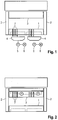
- the press includes u. a. a press table 1, 2 columns and a plunger 3. Between the press table 1 and the plunger 3, a die, not shown, and an unrepresented punch are arranged, the tool shells or a lower tool part wear.
- the servo unit comprises two servo pillows 4 in the form of hydraulic chambers, further comprising a servo pump 5 and a servomotor 6.
- a servo pump 5 In the press table. 1 bolts 7 are arranged. These are acted upon by the respective servo pad 4, so that they go up and down vertically.
- Each servo pad 4 may be associated with a different number of pins 7. So each servo pad can be assigned a single bolt. But it is also possible to assign two or more bolts a cushion.
- the operating medium of the servo unit is in this case a liquid. It could also be a pneumatic system.
- FIG. 2 the servo unit is assigned to the plunger 3. Only pump 5 is indicated.
- the servo unit is structurally integrated in the press table or in the ram.
- the servo unit is in FIG. 3 shown in more detail, again schematically. It is integrated in a stamp 8. Instead of the punch, the servo unit could also be integrated into a die.
- Each servo unit 4 acts on two bolts 7.
- Each servo chamber 4 is acted upon by a servo pump 5, which is driven by a servo motor. 6
- each servo unit 4 can be assigned its own servo motor pump set. But it can also be applied to a plurality of servo units 4 by a single servo motor pump set. In this case, a control valve (not shown here) is connected in front of each servo unit 4.
- control of the press or of the forming process will be linked to the control of the servo unit or units.
- the drawing device shown comprises a punch 8 and a sheet holder 9.
- the punch 8 is of slightly conical shape. It has a bottom mold surface 8.1 and a wall mold surface 8.2.
- the in the FIGS. 1 to 3 illustrated thought, including servo unit and bolt, is in FIG. 4 not shown. However, it should be understood that the thought of the pulling device according to FIG. 4 is realized.
- Stamp 8 is surrounded by the sheet holder 9.
- Sheet metal holder 9 has a support surface 9.1.
- Sheet holder 9 is annular.
- an inner die 10 It is at least approximately cylindrical. It is surrounded by an outer die 11. This is ring-shaped.
- the inner die 10 in turn has a bottom mold surface 10.1.
- the outer die 11 is annular. It has a wall molding surface 11.1, further a clamping surface 11.2 for clamping the drawing edge 12.3 of a workpiece 12 on the support surface 9.1 of the sheet holder 9.
- the workpiece 12 has emerged from a circular disk-shaped board. It comprises a bottom 12.1, a wall 12.2 and the said drawing edge 12.3.
- the clamping surface 11.2 of the outer die 11 is located approximately at the height of the bottom mold surface 10.1 of the inner die 10. At about the same height or higher is the support surface 9.1 of the sheet holder 9, sufficient for insertion of the workpiece 12th
- a workpiece 12 is inserted into the pulling device and clamped between the support surface 9.1 and the clamping surface 11.2.
- the inner die 10 and the outer die 11 move together with the preformed workpiece 12, as well as with the sheet holder 9 down.
- the said parts (inner die 10, outer die 11, plate holder 9 and preformed workpiece) have the same speed.
- the outer die 11 overtakes the inner die 10.
- FIG. 4 The drawing apparatus shown is only one station of a series of drawing stations. These are not shown here. In practice, they are connected in series in a workshop.
Landscapes
- Engineering & Computer Science (AREA)
- Mechanical Engineering (AREA)
- Shaping Metal By Deep-Drawing, Or The Like (AREA)
- Presses And Accessory Devices Thereof (AREA)
- Control Of Presses (AREA)
- Treatment And Processing Of Natural Fur Or Leather (AREA)
Description
Die Erfindung betrifft das Gebiet des Bearbeitens von Werkstücken aus Metall, beispielsweise aus Stahl oder anderen Metallen. Sie betrifft eine Vorrichtung zum Umformen eines Werkstückes, insbesondere einer Blechplatine.The invention relates to the field of machining workpieces of metal, for example of steel or other metals. It relates to a device for forming a workpiece, in particular a sheet metal blank.
Das Bearbeiten eines Werkstückes kann jegliche Vorgänge umfassen, beispielsweise das Schneiden, Pressen, Ziehen, Umformen.The machining of a workpiece may include any operations such as cutting, pressing, drawing, forming.
Bei den Werkstücken handelt es sich häufig um topfförmige Bauteile. Topfförmige Bauteile umfassen einen Boden, eine Topfwand sowie einen Ziehrand. Ein solches Bauteil wird häufig als Federtopf verwendet, um die Enden einer Spiralfeder aufzunehmen. Sie finden besonders in der Automobilindustrie vielfache Verwendung.The workpieces are often cup-shaped components. Pot-shaped components include a bottom, a pot wall and a drawing edge. Such a component is often used as a spring cup to accommodate the ends of a coil spring. They find particular use in the automotive industry in many ways.
Problematisch bei der Herstellung solcher Federtöpfe sind hochfeste Stähle. Diese haben zwar den Vorteil, dass sie extrem hohe Zugfestigkeiten aufweisen, und dass daher Stähle geringerer Dicke verwendet werden können, und somit auch geringeren Gewichtes. Solche Stähle sind jedoch relativ spröde und neigen zum Reißen. Dies tritt insbesondere beim Umformen an den hochbeanspruchten Übergangsbereichen auf. Das Reißen tritt insbesondere im Übergangsbereich zwischen Topfboden und Topfwand sowie zwischen Topfwand und Ziehrand auf.Problematic in the production of such spring pots are high-strength steels. Although these have the advantage that they have extremely high tensile strengths, and therefore steels smaller thickness can be used, and thus also lower weight. However, such steels are relatively brittle and tend to crack. This occurs especially when forming on the highly stressed transition areas. The tearing occurs in particular in the transition region between the bottom of the pot and the pot wall and between the pot wall and the drawing edge.
Bei allen bekannten Vorrichtungen besteht die Gefahr des Reißens des Werkstückes beim Umformprozess. Ein solches Reißen tritt vor allem in den Kantenbereichen des Werkstückes auf sowie bei größeren Ziehtiefen.In all known devices there is a risk of tearing the workpiece during the forming process. Such tearing occurs especially in the edge regions of the workpiece and at larger drawing depths.
Beim Stande der Technik sind ein oder mehrere Ziehkissen vorgesehen, die während des Ziehvorganges im Verdrängungsbetrieb sich so schnell bewegen, wie der Pressenstößel. Auch während des Arbeitsvorganges wird das Stößelkissen mit Stößelgeschwindigkeit verdrängt.In the prior art, one or more die cushions are provided which move during the drawing process in displacement mode as fast as the press ram. Also during the operation, the plunger cushion is displaced with ram speed.
Der Erfindung liegt die Aufgabe zugrunde, eine Vorrichtung, eine Anlage, ein Verfahren und ein Werkstück derart zu gestalten, dass hochfeste Stähle umformbar sind, ohne dass ein Reißen in den Kantenbereichen auftritt, und dass eine größere Ziehtiefe als bisher erreicht wird.The invention has for its object to make a device, a system, a method and a workpiece such that high-strength steels are deformable without tearing occurs in the edge regions, and that a greater draw depth than previously achieved.
Diese Aufgabe wird mittels einer Vorrichtung gemäß Anspruch 1 gelöst.This object is achieved by means of a device according to
Die Erfindung hat zahlreiche Vorteile:
- Der Ziehprozess selbst wird gesteuert, nicht etwas anderes.
- Die im
Patentanspruch 1 genannten Antriebe wirken auf das betreffende Werkzeugteil unmittelbar, das heißt ohne Zwischenschalten von funktionalen Teilen. Teile, die allein dem Übertragen der Kräfte dienen, zum Beispiel die Bolzen, können dabei verwendet werden. Jedoch ist auch eine mittelbare Einwirkung möglich.
- The drawing process itself is controlled, not something else.
- The drives mentioned in
claim 1 act directly on the relevant tool part, that is, without interposition of functional parts. Parts that serve only to transmit the forces, such as the bolts, can be used. However, an indirect action is possible.
Es hat sich gezeigt, dass durch das Zwischenschalten eines oder mehrerer Servo-Einheiten die genannten Bolzen nicht schlagartig, sondern sanfter als bisher beaufschlagt werden. Der Beaufschlagungsvorgang und damit auch die Einwirkung der Bolzen auf das Werkstück vollzieht sich innerhalb einer Zeitspanne, die nur wenige Millisekunden länger dauert, als bei bekannten Vorrichtungen. Damit wird die Rissgefahr erheblich minimiert, und es entstehen Werkstücke von hoher Qualität und Festigkeit.It has been shown that by interposing one or more servo units, the abovementioned bolts are not impacted abruptly, but more gently than before. The loading process and thus the action of the bolt on the workpiece takes place within a period of time that lasts only a few milliseconds longer than in known devices. This minimizes the risk of cracking and results in workpieces of high quality and strength.
Gemäß einem weiteren Gedanken der Erfindung wird die Vorrichtung derart gestaltet, dass die Innenmatrize und die Außenmatrize während des Umformvorganges mit unterschiedlichen Geschwindigkeiten in Ziehrichtung verfahren werden können. Hierzu werden der Innenmatrize und der Außenmatrize - gegebenenfalls zusammen mit dem Blechhalter - jeweils ein besonderer Antrieb zugeordnet, der diese beiden während des Umformvorganges mit unterschiedlichen Geschwindigkeiten in Ziehrichtung verfährt - im Folgenden "Variotempo-Einheit" genannt. Bei einer Presse mit Variotempo-Einheit bewegt sich die Servo-Einheit mit größerer Geschwindigkeit, als der Stößel der Presse in Ziehrichtung, somit in Richtung des Stößels.According to a further aspect of the invention, the device is designed such that the inner die and the outer die can be moved at different speeds in the drawing direction during the forming process. For this purpose, the inner die and the outer die - optionally together with the blank holder - each associated with a special drive, which moves these two during the forming process at different speeds in the drawing direction - hereinafter called "Variotempo unit". In a press with a variotempo unit, the servo unit moves at a faster speed than the plunger of the press in the pulling direction, thus in the direction of the plunger.
Es können mehrere Variotempo-Einheiten vorgesehen werden, über die Wirkungsfläche der Presse verteilt. Die kann von Bedeutung bei großen Bauteilen sein, beispielsweise bei Kotflügeln für Automobile. Bei solchen Bauteilen kann die Belastung des Werkstückes - während des Umformens oder im Betrieb - besonders hoch sein, so dass es sich empfiehlt, beim Umformen eine Variotempo-Einheit an den entsprechenden Stellen des Werkstückes vorzusehen.Several variotempo units can be provided, distributed over the effective area of the press. This can be important in large components, for example, in fenders for automobiles. In such components, the load on the workpiece - during forming or in operation - be particularly high, so it is recommended to provide a Variotempo unit at the corresponding points of the workpiece during forming.
Eine Variotempo-Einheit kann im Pressentisch oder im Pressenstößel oder in diesen beiden angeordnet sein.A variotempo unit can be arranged in the press table or in the press ram or in these two.
Sie kann angeordnet werden an oder in einer Schwebeplatte, dies ist eine Platte, die die Presskraft auf eine Fläche verteilt.It can be arranged on or in a floating plate, this is a plate that distributes the pressing force on a surface.
Variotempo-Einheiten lassen sich auch in existierende Pressenanlagen nachträglich einbauen.Variotempo units can also be retrofitted to existing press systems.
Die Erfindung ist anhand der Zeichnung näher erläutert. Darin ist im Einzelnen Folgendes dargestellt:
Figur 1- zeigt schematisch eine Presse mit integrierter Servo-Einheit. Dabei ist die Servo-Einheit dem Pressentisch zugeordnet.
Figur 2- zeigt schematisch eine Presse mit integrierter Servo-Einheit. Dabei ist die Servo-Einheit dem Stößel der Presse zugeordnet.
Figur 3- zeigt in schematischer Darstellung eine Servo-Einheit.
Figur 4- zeigt in schematischer Darstellung und im Aufriss eine Ziehvorrichtung mit bereits vorgeformtem Werkstück in erster Umformphase des Umformhubes; hierbei ist die Servo-Einheit weggelassen.
Figur 5- zeigt das Werkstück kurz vor Ende der zweiten Umformphase.
Figur 6- zeigt das Werkstück am Ende des Umformvorganges.
Figuren 7bis 12- veranschaulichen den Umformvorgang in sechs verschiedenen Umformstationen.
- FIG. 1
- schematically shows a press with integrated servo unit. The servo unit is assigned to the press table.
- FIG. 2
- schematically shows a press with integrated servo unit. The servo unit is assigned to the plunger of the press.
- FIG. 3
- shows a schematic representation of a servo unit.
- FIG. 4
- shows a schematic representation and in elevation a drawing device with already preformed workpiece in the first forming phase of Umformhubes; Here, the servo unit is omitted.
- FIG. 5
- shows the workpiece shortly before the end of the second forming phase.
- FIG. 6
- shows the workpiece at the end of the forming process.
- FIGS. 7 to 12
- illustrate the forming process in six different forming stations.
Die Presse umfasst u. a. einen Pressenstisch 1, Säulen 2 sowie einen Stößel 3. Zwischen dem Pressentisch 1 und dem Stößel 3 sind eine nicht dargestellte Matrize sowie ein nicht dargestellter Stempel angeordnet, die Werkzeugoberteile beziehungsweise ein Werkzeugunterteil tragen.The press includes u. a. a press table 1, 2 columns and a
Die Servo-Einheit umfasst zwei Servokissen 4 in Gestalt hydraulischer Kammern, ferner jeweils eine Servopumpe 5 sowie einen Servomotor 6. Im Pressentisch 1 sind Bolzen 7 angeordnet. Diese sind vom betreffenden Servokissen 4 beaufschlagbar, sodass sie vertikal auf- und abgehen.The servo unit comprises two
Jedes Servokissen 4 kann einer unterschiedlich großen Anzahl von Bolzen 7 zugeordnet sein. So kann jedem Servokissen ein einziger Bolzen zugeordnet sein. Es ist aber auch möglich, zwei oder mehrere Bolzen einem Kissen zuzuordnen.Each
Das Betriebsmedium der Servo-Einheit ist im vorliegenden Falle eine Flüssigkeit. Es könnte sich aber auch um ein pneumatisches System handeln.The operating medium of the servo unit is in this case a liquid. It could also be a pneumatic system.
In
Bei den beiden Ausführungsformen gemäß der
Die Servo-Einheit ist in
Man erkennt drei Servo-Einheiten 4. Jede Servo-Einheit 4 beaufschlagt zwei Bolzen 7. Jede Servokammer 4 ist von einer Servopumpe 5 beaufschlagt, die angetrieben ist von einem Servomotor 6.It can be seen three
Dabei kann jeder Servo-Einheit 4 ein eigener Servomotor-Pumpen-Satz zugeordnet werden. Es können aber auch mehrere Servo-Einheiten 4 von einem einzigen Servomotor-Pumpen-Satz beaufschlagt sein. Dabei ist vor jeder Servo-Einheit 4 ein hier nicht gezeigtes Regelventil geschaltet.In this case, each
Ganz allgemein wird die Steuerung der Presse beziehungsweise des Umformvorganges mit der Steuerung des oder der Servo-Einheit verknüpft sein.In general, the control of the press or of the forming process will be linked to the control of the servo unit or units.
Die in
Stempel 8 ist vom Blechhalter 9 umgeben. Blechhalter 9 weist eine Stützfläche 9.1 auf. Blechhalter 9 ist ringförmig.Stamp 8 is surrounded by the
Über dem Stempel 8 befindet sich eine innere Matrize 10. Sie ist wenigstens annähernd zylindrisch. Sie ist umgeben von einer äußeren Matrize 11. Diese ist ringförmig.Above the punch 8 is an
Die innere Matrize 10 weist wiederum eine Bodenformfläche 10.1 auf. Die äußere Matrize 11 ist ringförmig. Sie weist eine Wandformfläche 11.1 auf, ferner eine Einspannfläche 11.2 zum Festklemmen des Ziehrandes 12.3 eines Werkstückes 12 an der Stützfläche 9.1 des Blechhalters 9. Das Werkstück 12 ist aus einer kreisscheibenförmigen Platine hervorgegangen. Es umfasst einen Boden 12.1, eine Wand 12.2 sowie den genannten Ziehrand 12.3.The inner die 10 in turn has a bottom mold surface 10.1. The outer die 11 is annular. It has a wall molding surface 11.1, further a clamping surface 11.2 for clamping the drawing edge 12.3 of a
Die Ziehvorrichtung arbeitet wie folgt: Sie ist zunächst offen, das heißt die Einspannfläche 11.2 der äußeren Matrize 11 befindet sich etwa auf der Höhe der Bodenformfläche 10.1 der inneren Matrize 10. Auf etwa derselben Höhe oder noch höher befindet sich die Stützfläche 9.1 des Blechhalters 9, ausreichend zum Einführen des Werkstückes 12.It is initially open, that is, the clamping surface 11.2 of the
In dieser Phase wird ein Werkstück 12 in die Ziehvorrichtung eingelegt und zwischen der Stützfläche 9.1 und der Einspannfläche 11.2 eingespannt. Jetzt beginnt die eigentliche Arbeitsphase der Ziehvorrichtung. Dabei bewegen sich die innere Matrize 10 und die äußere Matrize 11 zusammen mit dem vorgeformten Werkstück 12, sowie auch mit dem Blechhalter 9 nach unten. Dabei haben die genannten Teile (innere Matrize 10, äußere Matrize 11, Blechhalter 9 und vorgeformtes Werkstück) dieselbe Geschwindigkeit.In this phase, a
Dies ändert sich gemäß der Erfindung in einer nachfolgenden Phase. Dabei überholt die innere Matrize 10 die äußere Matrize 11.This changes according to the invention in a subsequent phase. In this case, the
In einer weiteren, nachfolgenden Phase überholt hingegen die äußere Matrize 11 die innere Matrize 10.In a further, subsequent phase, on the other hand, the
Man beachte, dass dies auch umgekehrt sein kann.Note that this may be the other way around.
Die in
Dabei braucht nur eine einzige Ziehstation gemäß der Erfindung gestaltet zu sein, das heißt mit Antrieben versehen, die der inneren Matrize 10 einerseits, der äußeren Matrize 11 und dem Blechhalter 9 andererseits unterschiedliche Geschwindigkeiten während des Ziehvorganges verleihen können.It only needs a single drawing station designed according to the invention, that is provided with drives that can give the
Wie das Werkstück nach Verlassen der verschiedenen Ziehstationen aussieht, erkennt man aus den
Die Vorteile der Erfindung lassen sich wie folgt zusammenfassen:
- der Umformvorgang verläuft optimal und führt zu qualitativ hochwertigen Werkstücken
- die Erfindung ist besonders erfolgreich anwendbar bei großflächigen Werkstücken wie Kotflügel. Diese können an verschiedenen Stellen unterschiedlichen Umformvorgängen unterworfen werden, mit entsprechend unterschiedlichen Materialbeanspruchungen. Werden mehrere Variotempo-Einheiten eingesetzt, über die gesamte Werkstückfläche verteilt, so kann dem Rechnung getragen werden, indem das Verhältnis der Geschwindigkeiten von Innenmatrize und Außenmatrize beim Umformvorgang entsprechend bemessen wird.
- eine Gesamtregelung ist relativ einfach durchführbar, wobei das Regeln der Bewegungen der Bolzen einerseits und der gesamten Presse andererseits leicht aufeinander abgestimmt werden können
- das System lässt sich ohne weiteres in existierende Anlagen verwirklichen.
- The forming process is optimal and leads to high-quality workpieces
- The invention is particularly successfully applicable to large workpieces such as fenders. These can be subjected to different forming processes at different points, with correspondingly different material stresses. If several Variotempo units are used, distributed over the entire workpiece surface, so can be taken into account by the ratio of the speeds of inner die and outer die during the forming process is sized accordingly.
- an overall control is relatively easy to carry out, the rules of the movements of the bolts on the one hand and the entire press on the other hand can be easily matched
- The system can be easily implemented in existing plants.
- 11
- Pressentischpress table
- 22
- Säulepillar
- 33
- Stößeltappet
- 44
- Servo-Einheit in Gestalt hydraulischer KammernServo unit in the form of hydraulic chambers
- 55
- Servopumpepower steering pump
- 66
- Servomotorservomotor
- 77
- Bolzenbolt
- 88th
- Stempelstamp
- 8.18.1
- BodenformflächeFloor molding surface
- 8.28.2
- WandformflächeWall molding surface
- 99
- Blechhalterblankholder
- 9.19.1
- Stützflächesupport surface
- 1010
- innere Matrizeinner matrix
- 10.110.1
- BodenformflächeFloor molding surface
- 1111
- äußere Matrizeouter die
- 11.111.1
- WandformflächeWall molding surface
- 11.211.2
- Einspannflächechucking
- 1212
- Werkstückworkpiece
- 12.112.1
- WerkstückbodenWorkpiece ground
- 12.212.2
- WerkstückwandWorkpiece wall
- 12.312.3
- Ziehranddrawing border
Claims (6)
- A device for forming a sheet-metal blank, comprising the following features:1.1. a press frame having a pressing table (1), vertical columns (2), a cross head and a ram (3);1.2. a tool top part, comprising an outer and an inner dye (11, 10) as well as a tool base part, comprising a punch (8) and a sheet-metal holder (9);1.3. at least one drive, which is assigned to at least one of the two tool parts;characterized by the following features:1.4. the drive comprises:- a plurality of bolts (7), which are arranged vertically slideable in the pressing direction in the press table (1) and/or in the ram (3) and which act upon the respective tool part;- a plurality of pneumatic or hydraulic servo cushions, acting upon individual or groups of bolts (7) in the pressing direction;- a servo pump (5) loading the servo cushions, which are driven by a servomotor (6);1.5 the punch (8) comprises a base forming face (8.1) and a wall forming face (8.2);1.6 a annular sheet-metal holder (9) surrounding the punch (8) and having a support face (9.1);1.7 an inner die (10) having a base forming face (10.1);1.8 an outer die (11) having a wall forming face (11.1) and a clamping face (11.2) for gripping the peripheral surface of the emerging workpiece (12);1.9 one drive is in each case assigned to the inner die (10) on the one hand, and to the outer die (11) as well as to the sheet metal holder (9) on the other hand, which drive displaces the said two at different speeds in the drawing direction.
- The device according to claim 1, characterized in that one single servomotor - pump set is assigned to one hydraulic servo cushion.
- The device according to claim 1 or 2, characterized in that one single servomotor - pump set is assigned to one or multiple hydraulic servo cushions, and in that a control valve for controlling the pressure and/or the amount of the medium supplied to the servo cushion is assigned to the servomotor - pump set.
- The device according to any one of the claims 1 to 3, characterized in that an overall control is provided, which adjusts the control of the press and the control of the servo unit to one other.
- The device according to claim 4, characterized by a multitude of inner dies, which act upon the workpiece at different locations.
- A method for operating a device according to any one of the claims 1 to 5, characterized by one or more of the following method steps:I. during a starting period, both dies (10, 11) move in the same direction at equal speed;II. during an intermediate phase, both dies (10,11), in turn, move in the same direction, but the inner die (10) at a higher speed than the outer one (11);III. in a final phase, the inner die (10) stands still while the outer die (11) moves on at constant speed.
Priority Applications (3)
| Application Number | Priority Date | Filing Date | Title |
|---|---|---|---|
| PL14777300T PL3052257T3 (en) | 2013-09-30 | 2014-09-26 | Device for forming a workpiece made of sheet metal |
| SI201430352T SI3052257T1 (en) | 2013-09-30 | 2014-09-26 | Device for forming a workpiece made of sheet metal |
| HRP20171358TT HRP20171358T1 (en) | 2013-09-30 | 2014-09-26 | Device for shaping a workpiece made of sheet metal |
Applications Claiming Priority (2)
| Application Number | Priority Date | Filing Date | Title |
|---|---|---|---|
| DE102013219819.1A DE102013219819A1 (en) | 2013-09-30 | 2013-09-30 | Device for forming a workpiece from sheet metal |
| PCT/EP2014/070641 WO2015044363A1 (en) | 2013-09-30 | 2014-09-26 | Device for shaping a workpiece made of sheet metal |
Publications (2)
| Publication Number | Publication Date |
|---|---|
| EP3052257A1 EP3052257A1 (en) | 2016-08-10 |
| EP3052257B1 true EP3052257B1 (en) | 2017-08-16 |
Family
ID=51628119
Family Applications (1)
| Application Number | Title | Priority Date | Filing Date |
|---|---|---|---|
| EP14777300.6A Active EP3052257B1 (en) | 2013-09-30 | 2014-09-26 | Device for forming a workpiece made of sheet metal |
Country Status (20)
| Country | Link |
|---|---|
| US (1) | US11833565B2 (en) |
| EP (1) | EP3052257B1 (en) |
| JP (1) | JP6170633B2 (en) |
| KR (1) | KR101842812B1 (en) |
| CN (1) | CN105899307B (en) |
| BR (1) | BR112016006959B1 (en) |
| CA (1) | CA2921109C (en) |
| DE (1) | DE102013219819A1 (en) |
| DK (1) | DK3052257T3 (en) |
| ES (1) | ES2641219T3 (en) |
| HR (1) | HRP20171358T1 (en) |
| HU (1) | HUE034049T2 (en) |
| LT (1) | LT3052257T (en) |
| MX (1) | MX374449B (en) |
| PL (1) | PL3052257T3 (en) |
| PT (1) | PT3052257T (en) |
| RU (1) | RU2016111901A (en) |
| SI (1) | SI3052257T1 (en) |
| WO (1) | WO2015044363A1 (en) |
| ZA (1) | ZA201600930B (en) |
Families Citing this family (1)
| Publication number | Priority date | Publication date | Assignee | Title |
|---|---|---|---|---|
| CN109848275A (en) * | 2019-04-09 | 2019-06-07 | 马鞍山瑞恒精密制造有限公司 | The stretching of metal iron-clad, punching automation process units |
Family Cites Families (36)
| Publication number | Priority date | Publication date | Assignee | Title |
|---|---|---|---|---|
| US2294451A (en) * | 1940-03-29 | 1942-09-01 | Hydraulic Dev Corp Inc | Blank holder and die cushion cylinder having separate adjustable pressures |
| FR2270026B1 (en) * | 1974-05-06 | 1981-10-09 | Metal Box Co Ltd | |
| CH621271A5 (en) | 1977-06-15 | 1981-01-30 | Aluminiumwerke Ag Rorschach | |
| DE3022844A1 (en) * | 1980-06-19 | 1982-01-07 | Uniplanung Metall- und Kunststoffengineering GmbH & Co KG, 7552 Durmersheim | Deep-drawing tool assembly - has sheet holder supporting drawing cushion working together with further hydraulically connected drawing cushion |
| JPS5776998U (en) * | 1980-10-22 | 1982-05-12 | ||
| JPS584230U (en) * | 1981-06-30 | 1983-01-12 | 株式会社東芝 | mold equipment |
| JPS584230A (en) | 1981-06-30 | 1983-01-11 | 日本電気ホームエレクトロニクス株式会社 | Temperature fuse |
| AU564379B2 (en) * | 1982-08-30 | 1987-08-13 | Amada Company Limited | Press-bellow with pneumatic to hydraulic control |
| JPH02205210A (en) * | 1989-02-03 | 1990-08-15 | Akebono Brake Ind Co Ltd | Drawing press die |
| DE4008377A1 (en) * | 1990-03-15 | 1991-09-19 | Dieffenbacher Gmbh Maschf | Hydro-elastic deep drawing unit for sheet metal parts - improves prod. quality by using multipoint control via. several pressure cylinders |
| DE4112943A1 (en) * | 1991-04-20 | 1992-10-22 | Schuler Gmbh L | DRAWING DEVICE IN THE PRESS TABLE OF A PRESS |
| DE69203679T2 (en) * | 1991-09-04 | 1996-01-04 | Toyota Motor Co Ltd | Hydraulic cushion arrangement for a press with adjustable hydraulic energy supply for setting the initial pressure of the cylinders of the pressure bolts. |
| US5457980A (en) * | 1992-11-05 | 1995-10-17 | Toyota Jidosha Kabushiki Kaisha | Method and device for controlling, checking or optimizing pressure of cushion pin cylinders of press by discharging fluid or initial pressure |
| JP2776196B2 (en) * | 1993-04-28 | 1998-07-16 | トヨタ自動車株式会社 | Diagnosis method and device for pressure equalizing cushion device |
| JP3060908B2 (en) * | 1994-12-21 | 2000-07-10 | トヨタ自動車株式会社 | Press machine equalizer |
| AU681982B2 (en) * | 1995-02-10 | 1997-09-11 | Ogihara America Corporation | Stretch controlled forming mechanism and method for forming multiple guage welded blanks |
| DE19711780A1 (en) * | 1997-03-21 | 1998-09-24 | Schuler Pressen Gmbh & Co | Drawing device for drawing presses |
| US6014883A (en) * | 1998-06-08 | 2000-01-18 | Can Industry Products, Inc. | Apparatus and method for forming cup-shaped members |
| DE10254103B3 (en) | 2002-11-20 | 2004-04-15 | H&P Systec Gmbh | Deep drawing die and method to draw esp. metal plate blanks has drawing die with base and body formers, and body former applying friction force to part jacket during drawing |
| DE102005026818B4 (en) | 2004-06-24 | 2007-05-31 | Müller Weingarten AG | Die cushion device with NC drives |
| US7237423B1 (en) * | 2004-11-12 | 2007-07-03 | Miller Tool And Die Company Inc. | Apparatus for stretch forming blanks |
| CA2586049C (en) * | 2004-11-24 | 2011-03-29 | Honda Motor Co., Ltd. | Draw forming method and device |
| DE102006010648A1 (en) * | 2005-03-07 | 2006-09-14 | Müller Weingarten AG | Device for a metal working press for regulation of sheet holding force between the tool lower part and upper part, in forming of drawn parts, especiially for automobile industry, has elastic element in form of hydraulic or pneumatic cushion |
| JP4576639B2 (en) * | 2005-05-16 | 2010-11-10 | アイダエンジニアリング株式会社 | Die cushion device for press machine |
| CN2858098Y (en) * | 2005-08-10 | 2007-01-17 | 中国科学院金属研究所 | A sheet metal hydraulic or pneumatic forming device |
| JP2007075846A (en) * | 2005-09-13 | 2007-03-29 | Amino:Kk | Die cushion device of press |
| DE102006021150B4 (en) | 2006-05-06 | 2012-01-26 | Man Truck & Bus Ag | frame reinforcement |
| DE102007033943B4 (en) * | 2007-07-19 | 2018-05-17 | August Läpple GmbH & Co. KG | Device for forming workpieces |
| DE102007050581A1 (en) | 2007-10-23 | 2009-04-30 | Gerd Reitter | Molded part e.g. drawn part, deep drawing method, involves proceeding relative movement kinematics between die and female part during phase of deformation of drawn part base with low deformation rate than in phase of reformation of base |
| DE102007050580A1 (en) * | 2007-10-23 | 2009-04-30 | Gerd Reitter | Plate i.e. sheet metal plate shaping method for producing e.g. beer barrel, in mechanical press, involves applying reformation strength at internal area of plate against effective direction of deformation strength after deformation of area |
| KR20090008282U (en) * | 2008-02-13 | 2009-08-18 | 주식회사 신영 | Double Holder for Drawing Mold |
| DE102008047971B3 (en) * | 2008-09-18 | 2010-05-12 | Aisin Takaoka Co., Ltd., Toyota | Method and apparatus for press-hardening a metallic mold component |
| TR201007501A2 (en) * | 2010-09-13 | 2011-04-21 | Coşkunöz Metal Form Maki̇na Endüstri̇ Ve Ti̇c. A.Ş. | A cushion assembly for presses |
| DE102011001314C5 (en) * | 2011-03-16 | 2016-03-03 | Schuler Pressen Gmbh | Drawing press with two lockable rams |
| DE102012005635B3 (en) * | 2012-03-22 | 2013-06-27 | Allgaier Werke Gmbh | Apparatus, system and method for forming a sheet metal blank and a workpiece produced therewith |
| ES2853743T3 (en) * | 2012-09-28 | 2021-09-17 | Siemens Ag | Traction cushion drive and procedure for operating a traction cushion drive |
-
2013
- 2013-09-30 DE DE102013219819.1A patent/DE102013219819A1/en not_active Withdrawn
-
2014
- 2014-09-26 PT PT147773006T patent/PT3052257T/en unknown
- 2014-09-26 BR BR112016006959-5A patent/BR112016006959B1/en active IP Right Grant
- 2014-09-26 LT LTEP14777300.6T patent/LT3052257T/en unknown
- 2014-09-26 DK DK14777300.6T patent/DK3052257T3/en active
- 2014-09-26 KR KR1020167011228A patent/KR101842812B1/en active Active
- 2014-09-26 JP JP2016537350A patent/JP6170633B2/en active Active
- 2014-09-26 PL PL14777300T patent/PL3052257T3/en unknown
- 2014-09-26 MX MX2016003487A patent/MX374449B/en active IP Right Grant
- 2014-09-26 HR HRP20171358TT patent/HRP20171358T1/en unknown
- 2014-09-26 RU RU2016111901A patent/RU2016111901A/en not_active Application Discontinuation
- 2014-09-26 HU HUE14777300A patent/HUE034049T2/en unknown
- 2014-09-26 CA CA2921109A patent/CA2921109C/en active Active
- 2014-09-26 WO PCT/EP2014/070641 patent/WO2015044363A1/en not_active Ceased
- 2014-09-26 ES ES14777300.6T patent/ES2641219T3/en active Active
- 2014-09-26 CN CN201480050796.XA patent/CN105899307B/en active Active
- 2014-09-26 EP EP14777300.6A patent/EP3052257B1/en active Active
- 2014-09-26 SI SI201430352T patent/SI3052257T1/en unknown
-
2016
- 2016-02-10 ZA ZA2016/00930A patent/ZA201600930B/en unknown
- 2016-03-29 US US15/084,215 patent/US11833565B2/en active Active
Non-Patent Citations (1)
| Title |
|---|
| None * |
Also Published As
| Publication number | Publication date |
|---|---|
| PT3052257T (en) | 2017-10-02 |
| JP2016532563A (en) | 2016-10-20 |
| WO2015044363A1 (en) | 2015-04-02 |
| BR112016006959A2 (en) | 2017-08-01 |
| HUE034049T2 (en) | 2018-01-29 |
| CN105899307A (en) | 2016-08-24 |
| CN105899307B (en) | 2018-01-02 |
| DK3052257T3 (en) | 2017-09-25 |
| US11833565B2 (en) | 2023-12-05 |
| US20160207093A1 (en) | 2016-07-21 |
| CA2921109C (en) | 2019-07-30 |
| LT3052257T (en) | 2017-09-25 |
| CA2921109A1 (en) | 2015-04-02 |
| DE102013219819A1 (en) | 2015-04-02 |
| BR112016006959B1 (en) | 2022-07-26 |
| SI3052257T1 (en) | 2017-10-30 |
| MX2016003487A (en) | 2016-07-06 |
| JP6170633B2 (en) | 2017-07-26 |
| HRP20171358T1 (en) | 2017-11-03 |
| KR101842812B1 (en) | 2018-03-27 |
| PL3052257T3 (en) | 2018-02-28 |
| MX374449B (en) | 2025-03-06 |
| EP3052257A1 (en) | 2016-08-10 |
| RU2016111901A (en) | 2017-11-10 |
| ZA201600930B (en) | 2017-03-29 |
| ES2641219T3 (en) | 2017-11-08 |
| KR20160064190A (en) | 2016-06-07 |
Similar Documents
| Publication | Publication Date | Title |
|---|---|---|
| EP2785477B1 (en) | Device and method for machining a workpiece consisting of metal, particularly for producing a cup-shaped component for the automobile industry | |
| EP0418779B1 (en) | Method for manufacture of workpieces by punching, in particular in a precision counter punching tool | |
| EP2701861B1 (en) | Method and device for producing flangeless drawn parts | |
| DE102014222476B4 (en) | A heat treatment apparatus for hot stamping and molding using the like | |
| DE102011117066B4 (en) | Device for producing a hot-formed and press-hardened motor vehicle body component and method for production | |
| DE102011011013B4 (en) | Press plant for forming or processing metal components | |
| DE19842750B4 (en) | Method and production of deep-drawn hollow parts and drawing tool | |
| DE102010037950B4 (en) | Drawing press with static sheet metal holding | |
| EP1063028B2 (en) | Press for external hydroforming | |
| DE102006007224A1 (en) | Method and device for producing a cutout or opening in the wall of a formed by the hydroforming process component | |
| DE102015219416B3 (en) | Multiple tool for a punching device and punching device with a corresponding multiple tool | |
| DE102017114596A1 (en) | Method and device for regulating the deep-drawing process during the press stroke | |
| EP3052257B1 (en) | Device for forming a workpiece made of sheet metal | |
| DE102004054120B4 (en) | A method of forming a large sheet metal blank to a molded part, such as an outer skin part of a motor vehicle body | |
| DE102015215184B4 (en) | Tool for heat treatment of undercut components | |
| EP2353745B1 (en) | Tool and method for producing can bodies | |
| DE102014110400B4 (en) | Etagenpressumformwerkzeug | |
| WO2007028475A2 (en) | Method for producing press-hardened component | |
| DE2133522A1 (en) | Press force regulator for deep drawing presses | |
| WO2005021253A2 (en) | Hydraulic press and deep-drawing press | |
| EP3212346A1 (en) | Molding tool for producing hot-formed components | |
| EP2662161B1 (en) | Method for manufacturing a workpiece | |
| DE102005034256A1 (en) | Die cushion device of a press | |
| EP1396297B1 (en) | Device and method for deep-drawing | |
| DE3123319A1 (en) | METHOD AND DEVICE FOR BENDING SHEET SHEET SHEETS TO SHEET BODY BODIES IN CYLINDRICAL SHAPE |
Legal Events
| Date | Code | Title | Description |
|---|---|---|---|
| PUAI | Public reference made under article 153(3) epc to a published international application that has entered the european phase |
Free format text: ORIGINAL CODE: 0009012 |
|
| 17P | Request for examination filed |
Effective date: 20160211 |
|
| AK | Designated contracting states |
Kind code of ref document: A1 Designated state(s): AL AT BE BG CH CY CZ DE DK EE ES FI FR GB GR HR HU IE IS IT LI LT LU LV MC MK MT NL NO PL PT RO RS SE SI SK SM TR |
|
| AX | Request for extension of the european patent |
Extension state: BA ME |
|
| DAX | Request for extension of the european patent (deleted) | ||
| GRAP | Despatch of communication of intention to grant a patent |
Free format text: ORIGINAL CODE: EPIDOSNIGR1 |
|
| INTG | Intention to grant announced |
Effective date: 20170509 |
|
| GRAS | Grant fee paid |
Free format text: ORIGINAL CODE: EPIDOSNIGR3 |
|
| GRAA | (expected) grant |
Free format text: ORIGINAL CODE: 0009210 |
|
| AK | Designated contracting states |
Kind code of ref document: B1 Designated state(s): AL AT BE BG CH CY CZ DE DK EE ES FI FR GB GR HR HU IE IS IT LI LT LU LV MC MK MT NL NO PL PT RO RS SE SI SK SM TR |
|
| REG | Reference to a national code |
Ref country code: GB Ref legal event code: FG4D Free format text: NOT ENGLISH |
|
| REG | Reference to a national code |
Ref country code: CH Ref legal event code: EP |
|
| REG | Reference to a national code |
Ref country code: IE Ref legal event code: FG4D Free format text: LANGUAGE OF EP DOCUMENT: GERMAN |
|
| REG | Reference to a national code |
Ref country code: HR Ref legal event code: TUEP Ref document number: P20171358 Country of ref document: HR |
|
| REG | Reference to a national code |
Ref country code: RO Ref legal event code: EPE |
|
| REG | Reference to a national code |
Ref country code: AT Ref legal event code: REF Ref document number: 918567 Country of ref document: AT Kind code of ref document: T Effective date: 20170915 |
|
| REG | Reference to a national code |
Ref country code: FR Ref legal event code: PLFP Year of fee payment: 4 |
|
| REG | Reference to a national code |
Ref country code: DK Ref legal event code: T3 Effective date: 20170919 |
|
| REG | Reference to a national code |
Ref country code: DE Ref legal event code: R096 Ref document number: 502014005100 Country of ref document: DE |
|
| REG | Reference to a national code |
Ref country code: PT Ref legal event code: SC4A Ref document number: 3052257 Country of ref document: PT Date of ref document: 20171002 Kind code of ref document: T Free format text: AVAILABILITY OF NATIONAL TRANSLATION Effective date: 20170920 |
|
| REG | Reference to a national code |
Ref country code: SE Ref legal event code: TRGR |
|
| REG | Reference to a national code |
Ref country code: HR Ref legal event code: T1PR Ref document number: P20171358 Country of ref document: HR |
|
| REG | Reference to a national code |
Ref country code: ES Ref legal event code: FG2A Ref document number: 2641219 Country of ref document: ES Kind code of ref document: T3 Effective date: 20171108 |
|
| REG | Reference to a national code |
Ref country code: NL Ref legal event code: FP |
|
| REG | Reference to a national code |
Ref country code: HU Ref legal event code: AG4A Ref document number: E034049 Country of ref document: HU |
|
| PG25 | Lapsed in a contracting state [announced via postgrant information from national office to epo] |
Ref country code: NO Free format text: LAPSE BECAUSE OF FAILURE TO SUBMIT A TRANSLATION OF THE DESCRIPTION OR TO PAY THE FEE WITHIN THE PRESCRIBED TIME-LIMIT Effective date: 20171116 |
|
| REG | Reference to a national code |
Ref country code: SK Ref legal event code: T3 Ref document number: E 25351 Country of ref document: SK |
|
| PG25 | Lapsed in a contracting state [announced via postgrant information from national office to epo] |
Ref country code: IS Free format text: LAPSE BECAUSE OF FAILURE TO SUBMIT A TRANSLATION OF THE DESCRIPTION OR TO PAY THE FEE WITHIN THE PRESCRIBED TIME-LIMIT Effective date: 20171216 Ref country code: RS Free format text: LAPSE BECAUSE OF FAILURE TO SUBMIT A TRANSLATION OF THE DESCRIPTION OR TO PAY THE FEE WITHIN THE PRESCRIBED TIME-LIMIT Effective date: 20170816 |
|
| REG | Reference to a national code |
Ref country code: EE Ref legal event code: FG4A Ref document number: E014879 Country of ref document: EE Effective date: 20170929 |
|
| REG | Reference to a national code |
Ref country code: GR Ref legal event code: EP Ref document number: 20170402569 Country of ref document: GR Effective date: 20180309 |
|
| REG | Reference to a national code |
Ref country code: CH Ref legal event code: PL |
|
| REG | Reference to a national code |
Ref country code: DE Ref legal event code: R097 Ref document number: 502014005100 Country of ref document: DE |
|
| PG25 | Lapsed in a contracting state [announced via postgrant information from national office to epo] |
Ref country code: SM Free format text: LAPSE BECAUSE OF FAILURE TO SUBMIT A TRANSLATION OF THE DESCRIPTION OR TO PAY THE FEE WITHIN THE PRESCRIBED TIME-LIMIT Effective date: 20170816 Ref country code: MC Free format text: LAPSE BECAUSE OF FAILURE TO SUBMIT A TRANSLATION OF THE DESCRIPTION OR TO PAY THE FEE WITHIN THE PRESCRIBED TIME-LIMIT Effective date: 20170816 |
|
| PLBE | No opposition filed within time limit |
Free format text: ORIGINAL CODE: 0009261 |
|
| STAA | Information on the status of an ep patent application or granted ep patent |
Free format text: STATUS: NO OPPOSITION FILED WITHIN TIME LIMIT |
|
| 26N | No opposition filed |
Effective date: 20180517 |
|
| PG25 | Lapsed in a contracting state [announced via postgrant information from national office to epo] |
Ref country code: LI Free format text: LAPSE BECAUSE OF NON-PAYMENT OF DUE FEES Effective date: 20170930 Ref country code: CH Free format text: LAPSE BECAUSE OF NON-PAYMENT OF DUE FEES Effective date: 20170930 |
|
| REG | Reference to a national code |
Ref country code: FR Ref legal event code: PLFP Year of fee payment: 5 |
|
| PG25 | Lapsed in a contracting state [announced via postgrant information from national office to epo] |
Ref country code: MT Free format text: LAPSE BECAUSE OF FAILURE TO SUBMIT A TRANSLATION OF THE DESCRIPTION OR TO PAY THE FEE WITHIN THE PRESCRIBED TIME-LIMIT Effective date: 20170816 |
|
| REG | Reference to a national code |
Ref country code: DE Ref legal event code: R082 Ref document number: 502014005100 Country of ref document: DE Representative=s name: BOSCH JEHLE PATENTANWALTSGESELLSCHAFT MBH, DE |
|
| REG | Reference to a national code |
Ref country code: HR Ref legal event code: ODRP Ref document number: P20171358 Country of ref document: HR Payment date: 20190917 Year of fee payment: 6 |
|
| PG25 | Lapsed in a contracting state [announced via postgrant information from national office to epo] |
Ref country code: CY Free format text: LAPSE BECAUSE OF FAILURE TO SUBMIT A TRANSLATION OF THE DESCRIPTION OR TO PAY THE FEE WITHIN THE PRESCRIBED TIME-LIMIT Effective date: 20170816 |
|
| PG25 | Lapsed in a contracting state [announced via postgrant information from national office to epo] |
Ref country code: MK Free format text: LAPSE BECAUSE OF FAILURE TO SUBMIT A TRANSLATION OF THE DESCRIPTION OR TO PAY THE FEE WITHIN THE PRESCRIBED TIME-LIMIT Effective date: 20170816 |
|
| PG25 | Lapsed in a contracting state [announced via postgrant information from national office to epo] |
Ref country code: TR Free format text: LAPSE BECAUSE OF FAILURE TO SUBMIT A TRANSLATION OF THE DESCRIPTION OR TO PAY THE FEE WITHIN THE PRESCRIBED TIME-LIMIT Effective date: 20170816 |
|
| PG25 | Lapsed in a contracting state [announced via postgrant information from national office to epo] |
Ref country code: AL Free format text: LAPSE BECAUSE OF FAILURE TO SUBMIT A TRANSLATION OF THE DESCRIPTION OR TO PAY THE FEE WITHIN THE PRESCRIBED TIME-LIMIT Effective date: 20170816 |
|
| REG | Reference to a national code |
Ref country code: HR Ref legal event code: ODRP Ref document number: P20171358 Country of ref document: HR Payment date: 20200917 Year of fee payment: 7 |
|
| REG | Reference to a national code |
Ref country code: HR Ref legal event code: ODRP Ref document number: P20171358 Country of ref document: HR Payment date: 20210917 Year of fee payment: 8 |
|
| REG | Reference to a national code |
Ref country code: HR Ref legal event code: ODRP Ref document number: P20171358 Country of ref document: HR Payment date: 20220914 Year of fee payment: 9 |
|
| REG | Reference to a national code |
Ref legal event code: R082 Ref document number: 502014005100 Country of ref document: DE Ref country code: DE Ref legal event code: R082 Ref document number: 502014005100 Country of ref document: DE Representative=s name: BOSCH JEHLE PATENTANWALTSGESELLSCHAFT MBH, DE |
|
| REG | Reference to a national code |
Ref country code: DE Ref legal event code: R082 Ref document number: 502014005100 Country of ref document: DE Representative=s name: BOSCH JEHLE PATENTANWALTSGESELLSCHAFT MBH, DE |
|
| REG | Reference to a national code |
Ref country code: HR Ref legal event code: ODRP Ref document number: P20171358 Country of ref document: HR Payment date: 20230915 Year of fee payment: 10 |
|
| REG | Reference to a national code |
Ref country code: HR Ref legal event code: ODRP Ref document number: P20171358 Country of ref document: HR Payment date: 20240920 Year of fee payment: 11 |
|
| PGFP | Annual fee paid to national office [announced via postgrant information from national office to epo] |
Ref country code: PT Payment date: 20250630 Year of fee payment: 12 |
|
| PGFP | Annual fee paid to national office [announced via postgrant information from national office to epo] |
Ref country code: SK Payment date: 20250625 Year of fee payment: 12 |
|
| PGFP | Annual fee paid to national office [announced via postgrant information from national office to epo] |
Ref country code: FI Payment date: 20250922 Year of fee payment: 12 |
|
| PGFP | Annual fee paid to national office [announced via postgrant information from national office to epo] |
Ref country code: LT Payment date: 20250911 Year of fee payment: 12 Ref country code: DE Payment date: 20250725 Year of fee payment: 12 Ref country code: DK Payment date: 20250922 Year of fee payment: 12 |
|
| REG | Reference to a national code |
Ref country code: HR Ref legal event code: ODRP Ref document number: P20171358 Country of ref document: HR Payment date: 20250916 Year of fee payment: 12 |
|
| PGFP | Annual fee paid to national office [announced via postgrant information from national office to epo] |
Ref country code: GR Payment date: 20250918 Year of fee payment: 12 |
|
| PGFP | Annual fee paid to national office [announced via postgrant information from national office to epo] |
Ref country code: PL Payment date: 20250912 Year of fee payment: 12 Ref country code: NL Payment date: 20250922 Year of fee payment: 12 Ref country code: LU Payment date: 20250922 Year of fee payment: 12 |
|
| PGFP | Annual fee paid to national office [announced via postgrant information from national office to epo] |
Ref country code: BG Payment date: 20250917 Year of fee payment: 12 Ref country code: HU Payment date: 20250917 Year of fee payment: 12 Ref country code: BE Payment date: 20250919 Year of fee payment: 12 Ref country code: GB Payment date: 20250923 Year of fee payment: 12 |
|
| PGFP | Annual fee paid to national office [announced via postgrant information from national office to epo] |
Ref country code: HR Payment date: 20250916 Year of fee payment: 12 |
|
| PGFP | Annual fee paid to national office [announced via postgrant information from national office to epo] |
Ref country code: AT Payment date: 20250918 Year of fee payment: 12 Ref country code: FR Payment date: 20250924 Year of fee payment: 12 |
|
| PGFP | Annual fee paid to national office [announced via postgrant information from national office to epo] |
Ref country code: SE Payment date: 20250922 Year of fee payment: 12 |
|
| PGFP | Annual fee paid to national office [announced via postgrant information from national office to epo] |
Ref country code: IE Payment date: 20250919 Year of fee payment: 12 Ref country code: EE Payment date: 20250922 Year of fee payment: 12 Ref country code: CZ Payment date: 20250912 Year of fee payment: 12 |
|
| PGFP | Annual fee paid to national office [announced via postgrant information from national office to epo] |
Ref country code: RO Payment date: 20250918 Year of fee payment: 12 |
|
| PGFP | Annual fee paid to national office [announced via postgrant information from national office to epo] |
Ref country code: LV Payment date: 20250923 Year of fee payment: 12 |
|
| PGFP | Annual fee paid to national office [announced via postgrant information from national office to epo] |
Ref country code: SI Payment date: 20250915 Year of fee payment: 12 |
|
| PGFP | Annual fee paid to national office [announced via postgrant information from national office to epo] |
Ref country code: IT Payment date: 20250930 Year of fee payment: 12 |
|
| PGFP | Annual fee paid to national office [announced via postgrant information from national office to epo] |
Ref country code: ES Payment date: 20251020 Year of fee payment: 12 |