EP3052176B1 - Radial- und transendokardialer freisetzungskatheter - Google Patents
Radial- und transendokardialer freisetzungskatheter Download PDFInfo
- Publication number
- EP3052176B1 EP3052176B1 EP14848948.7A EP14848948A EP3052176B1 EP 3052176 B1 EP3052176 B1 EP 3052176B1 EP 14848948 A EP14848948 A EP 14848948A EP 3052176 B1 EP3052176 B1 EP 3052176B1
- Authority
- EP
- European Patent Office
- Prior art keywords
- catheter
- needle
- lumen
- guide
- delivery
- Prior art date
- Legal status (The legal status is an assumption and is not a legal conclusion. Google has not performed a legal analysis and makes no representation as to the accuracy of the status listed.)
- Active
Links
- 238000002347 injection Methods 0.000 claims description 50
- 239000007924 injection Substances 0.000 claims description 50
- 230000035515 penetration Effects 0.000 claims description 23
- 210000005242 cardiac chamber Anatomy 0.000 claims description 18
- BASFCYQUMIYNBI-UHFFFAOYSA-N platinum Chemical compound [Pt] BASFCYQUMIYNBI-UHFFFAOYSA-N 0.000 claims description 10
- 239000002872 contrast media Substances 0.000 claims description 7
- 239000002184 metal Substances 0.000 claims description 6
- 229910052751 metal Inorganic materials 0.000 claims description 6
- 239000007972 injectable composition Substances 0.000 claims description 3
- 210000002321 radial artery Anatomy 0.000 description 24
- 238000000034 method Methods 0.000 description 23
- 230000001225 therapeutic effect Effects 0.000 description 20
- 210000001519 tissue Anatomy 0.000 description 19
- 239000000463 material Substances 0.000 description 18
- 238000013461 design Methods 0.000 description 17
- 230000008901 benefit Effects 0.000 description 16
- 238000001802 infusion Methods 0.000 description 14
- 230000009977 dual effect Effects 0.000 description 11
- 239000003814 drug Substances 0.000 description 10
- 230000000149 penetrating effect Effects 0.000 description 10
- 230000001681 protective effect Effects 0.000 description 8
- 238000002560 therapeutic procedure Methods 0.000 description 8
- 239000003795 chemical substances by application Substances 0.000 description 7
- 239000004593 Epoxy Substances 0.000 description 6
- 241001474791 Proboscis Species 0.000 description 6
- 210000004027 cell Anatomy 0.000 description 6
- 210000004165 myocardium Anatomy 0.000 description 6
- 239000000126 substance Substances 0.000 description 6
- 229940124597 therapeutic agent Drugs 0.000 description 6
- 238000013459 approach Methods 0.000 description 5
- 238000005452 bending Methods 0.000 description 5
- 210000001105 femoral artery Anatomy 0.000 description 5
- 239000012530 fluid Substances 0.000 description 5
- 230000007246 mechanism Effects 0.000 description 5
- 229910001220 stainless steel Inorganic materials 0.000 description 5
- 239000010935 stainless steel Substances 0.000 description 5
- 239000010963 304 stainless steel Substances 0.000 description 4
- 102000010834 Extracellular Matrix Proteins Human genes 0.000 description 4
- 108010037362 Extracellular Matrix Proteins Proteins 0.000 description 4
- 229910000589 SAE 304 stainless steel Inorganic materials 0.000 description 4
- 208000005392 Spasm Diseases 0.000 description 4
- 229940079593 drug Drugs 0.000 description 4
- 210000002744 extracellular matrix Anatomy 0.000 description 4
- 210000005003 heart tissue Anatomy 0.000 description 4
- 210000005240 left ventricle Anatomy 0.000 description 4
- 238000004519 manufacturing process Methods 0.000 description 4
- 239000002245 particle Substances 0.000 description 4
- 210000005166 vasculature Anatomy 0.000 description 4
- 238000004804 winding Methods 0.000 description 4
- 239000004952 Polyamide Substances 0.000 description 3
- 239000000853 adhesive Substances 0.000 description 3
- 230000001070 adhesive effect Effects 0.000 description 3
- 230000000747 cardiac effect Effects 0.000 description 3
- 230000001413 cellular effect Effects 0.000 description 3
- 239000002131 composite material Substances 0.000 description 3
- 238000005516 engineering process Methods 0.000 description 3
- 229910001000 nickel titanium Inorganic materials 0.000 description 3
- HLXZNVUGXRDIFK-UHFFFAOYSA-N nickel titanium Chemical compound [Ti].[Ti].[Ti].[Ti].[Ti].[Ti].[Ti].[Ti].[Ti].[Ti].[Ti].[Ni].[Ni].[Ni].[Ni].[Ni].[Ni].[Ni].[Ni].[Ni].[Ni].[Ni].[Ni].[Ni].[Ni] HLXZNVUGXRDIFK-UHFFFAOYSA-N 0.000 description 3
- 239000011236 particulate material Substances 0.000 description 3
- 229920002647 polyamide Polymers 0.000 description 3
- 229910000679 solder Inorganic materials 0.000 description 3
- 210000000130 stem cell Anatomy 0.000 description 3
- 208000005189 Embolism Diseases 0.000 description 2
- 206010019280 Heart failures Diseases 0.000 description 2
- PXHVJJICTQNCMI-UHFFFAOYSA-N Nickel Chemical compound [Ni] PXHVJJICTQNCMI-UHFFFAOYSA-N 0.000 description 2
- 239000004696 Poly ether ether ketone Substances 0.000 description 2
- 229920002614 Polyether block amide Polymers 0.000 description 2
- 239000004830 Super Glue Substances 0.000 description 2
- JUPQTSLXMOCDHR-UHFFFAOYSA-N benzene-1,4-diol;bis(4-fluorophenyl)methanone Chemical compound OC1=CC=C(O)C=C1.C1=CC(F)=CC=C1C(=O)C1=CC=C(F)C=C1 JUPQTSLXMOCDHR-UHFFFAOYSA-N 0.000 description 2
- 239000011248 coating agent Substances 0.000 description 2
- 238000000576 coating method Methods 0.000 description 2
- 230000008602 contraction Effects 0.000 description 2
- 238000011161 development Methods 0.000 description 2
- 229920006332 epoxy adhesive Polymers 0.000 description 2
- FGBJXOREULPLGL-UHFFFAOYSA-N ethyl cyanoacrylate Chemical compound CCOC(=O)C(=C)C#N FGBJXOREULPLGL-UHFFFAOYSA-N 0.000 description 2
- 238000001125 extrusion Methods 0.000 description 2
- 238000002594 fluoroscopy Methods 0.000 description 2
- 230000023597 hemostasis Effects 0.000 description 2
- 238000002595 magnetic resonance imaging Methods 0.000 description 2
- 239000004005 microsphere Substances 0.000 description 2
- 230000002107 myocardial effect Effects 0.000 description 2
- 229910052697 platinum Inorganic materials 0.000 description 2
- 229920002530 polyetherether ketone Polymers 0.000 description 2
- 229920000642 polymer Polymers 0.000 description 2
- 239000004810 polytetrafluoroethylene Substances 0.000 description 2
- 229920001343 polytetrafluoroethylene Polymers 0.000 description 2
- 239000002002 slurry Substances 0.000 description 2
- 239000007787 solid Substances 0.000 description 2
- 230000007704 transition Effects 0.000 description 2
- 229910015363 Au—Sn Inorganic materials 0.000 description 1
- 238000003462 Bender reaction Methods 0.000 description 1
- RYGMFSIKBFXOCR-UHFFFAOYSA-N Copper Chemical compound [Cu] RYGMFSIKBFXOCR-UHFFFAOYSA-N 0.000 description 1
- FAPWRFPIFSIZLT-UHFFFAOYSA-M Sodium chloride Chemical compound [Na+].[Cl-] FAPWRFPIFSIZLT-UHFFFAOYSA-M 0.000 description 1
- 206010000891 acute myocardial infarction Diseases 0.000 description 1
- 230000002776 aggregation Effects 0.000 description 1
- 238000004220 aggregation Methods 0.000 description 1
- 229910052782 aluminium Inorganic materials 0.000 description 1
- XAGFODPZIPBFFR-UHFFFAOYSA-N aluminium Chemical compound [Al] XAGFODPZIPBFFR-UHFFFAOYSA-N 0.000 description 1
- 238000000137 annealing Methods 0.000 description 1
- 230000003466 anti-cipated effect Effects 0.000 description 1
- 210000001765 aortic valve Anatomy 0.000 description 1
- 210000005249 arterial vasculature Anatomy 0.000 description 1
- 210000001367 artery Anatomy 0.000 description 1
- 230000000712 assembly Effects 0.000 description 1
- 238000000429 assembly Methods 0.000 description 1
- 230000004888 barrier function Effects 0.000 description 1
- 238000010009 beating Methods 0.000 description 1
- 239000012620 biological material Substances 0.000 description 1
- 238000013131 cardiovascular procedure Methods 0.000 description 1
- 230000001684 chronic effect Effects 0.000 description 1
- 238000010276 construction Methods 0.000 description 1
- 229940039231 contrast media Drugs 0.000 description 1
- 229910052802 copper Inorganic materials 0.000 description 1
- 239000010949 copper Substances 0.000 description 1
- 238000002716 delivery method Methods 0.000 description 1
- 238000009795 derivation Methods 0.000 description 1
- 239000000032 diagnostic agent Substances 0.000 description 1
- 229940039227 diagnostic agent Drugs 0.000 description 1
- 229910003460 diamond Inorganic materials 0.000 description 1
- 239000010432 diamond Substances 0.000 description 1
- 238000005323 electroforming Methods 0.000 description 1
- 238000005538 encapsulation Methods 0.000 description 1
- 239000003822 epoxy resin Substances 0.000 description 1
- 230000008014 freezing Effects 0.000 description 1
- 238000007710 freezing Methods 0.000 description 1
- 230000006870 function Effects 0.000 description 1
- 230000004927 fusion Effects 0.000 description 1
- 239000003292 glue Substances 0.000 description 1
- 210000004013 groin Anatomy 0.000 description 1
- 230000010247 heart contraction Effects 0.000 description 1
- 238000009998 heat setting Methods 0.000 description 1
- 238000003384 imaging method Methods 0.000 description 1
- 238000013152 interventional procedure Methods 0.000 description 1
- 238000011835 investigation Methods 0.000 description 1
- 230000000302 ischemic effect Effects 0.000 description 1
- 239000007788 liquid Substances 0.000 description 1
- 238000007726 management method Methods 0.000 description 1
- 238000013507 mapping Methods 0.000 description 1
- 238000012986 modification Methods 0.000 description 1
- 230000004048 modification Effects 0.000 description 1
- 208000031225 myocardial ischemia Diseases 0.000 description 1
- 229910052759 nickel Inorganic materials 0.000 description 1
- 238000012856 packing Methods 0.000 description 1
- 230000037361 pathway Effects 0.000 description 1
- 239000004033 plastic Substances 0.000 description 1
- HWLDNSXPUQTBOD-UHFFFAOYSA-N platinum-iridium alloy Chemical compound [Ir].[Pt] HWLDNSXPUQTBOD-UHFFFAOYSA-N 0.000 description 1
- 229920000647 polyepoxide Polymers 0.000 description 1
- 238000005086 pumping Methods 0.000 description 1
- 230000005855 radiation Effects 0.000 description 1
- 230000009467 reduction Effects 0.000 description 1
- 210000005241 right ventricle Anatomy 0.000 description 1
- 238000005549 size reduction Methods 0.000 description 1
- 239000000779 smoke Substances 0.000 description 1
- 239000011780 sodium chloride Substances 0.000 description 1
- 230000003068 static effect Effects 0.000 description 1
- 238000002604 ultrasonography Methods 0.000 description 1
- 230000002861 ventricular Effects 0.000 description 1
- 230000035899 viability Effects 0.000 description 1
- XLYOFNOQVPJJNP-UHFFFAOYSA-N water Substances O XLYOFNOQVPJJNP-UHFFFAOYSA-N 0.000 description 1
- 238000003466 welding Methods 0.000 description 1
Images


Classifications
-
- A—HUMAN NECESSITIES
- A61—MEDICAL OR VETERINARY SCIENCE; HYGIENE
- A61M—DEVICES FOR INTRODUCING MEDIA INTO, OR ONTO, THE BODY; DEVICES FOR TRANSDUCING BODY MEDIA OR FOR TAKING MEDIA FROM THE BODY; DEVICES FOR PRODUCING OR ENDING SLEEP OR STUPOR
- A61M25/00—Catheters; Hollow probes
- A61M25/0067—Catheters; Hollow probes characterised by the distal end, e.g. tips
- A61M25/0082—Catheter tip comprising a tool
- A61M25/0084—Catheter tip comprising a tool being one or more injection needles
-
- A—HUMAN NECESSITIES
- A61—MEDICAL OR VETERINARY SCIENCE; HYGIENE
- A61M—DEVICES FOR INTRODUCING MEDIA INTO, OR ONTO, THE BODY; DEVICES FOR TRANSDUCING BODY MEDIA OR FOR TAKING MEDIA FROM THE BODY; DEVICES FOR PRODUCING OR ENDING SLEEP OR STUPOR
- A61M25/00—Catheters; Hollow probes
- A61M25/01—Introducing, guiding, advancing, emplacing or holding catheters
- A61M25/06—Body-piercing guide needles or the like
- A61M25/0606—"Over-the-needle" catheter assemblies, e.g. I.V. catheters
-
- A—HUMAN NECESSITIES
- A61—MEDICAL OR VETERINARY SCIENCE; HYGIENE
- A61M—DEVICES FOR INTRODUCING MEDIA INTO, OR ONTO, THE BODY; DEVICES FOR TRANSDUCING BODY MEDIA OR FOR TAKING MEDIA FROM THE BODY; DEVICES FOR PRODUCING OR ENDING SLEEP OR STUPOR
- A61M25/00—Catheters; Hollow probes
- A61M25/01—Introducing, guiding, advancing, emplacing or holding catheters
- A61M25/09—Guide wires
-
- A—HUMAN NECESSITIES
- A61—MEDICAL OR VETERINARY SCIENCE; HYGIENE
- A61B—DIAGNOSIS; SURGERY; IDENTIFICATION
- A61B17/00—Surgical instruments, devices or methods, e.g. tourniquets
- A61B17/00234—Surgical instruments, devices or methods, e.g. tourniquets for minimally invasive surgery
- A61B2017/00238—Type of minimally invasive operation
- A61B2017/00243—Type of minimally invasive operation cardiac
- A61B2017/00247—Making holes in the wall of the heart, e.g. laser Myocardial revascularization
-
- A—HUMAN NECESSITIES
- A61—MEDICAL OR VETERINARY SCIENCE; HYGIENE
- A61B—DIAGNOSIS; SURGERY; IDENTIFICATION
- A61B90/00—Instruments, implements or accessories specially adapted for surgery or diagnosis and not covered by any of the groups A61B1/00 - A61B50/00, e.g. for luxation treatment or for protecting wound edges
- A61B90/03—Automatic limiting or abutting means, e.g. for safety
- A61B2090/033—Abutting means, stops, e.g. abutting on tissue or skin
- A61B2090/036—Abutting means, stops, e.g. abutting on tissue or skin abutting on tissue or skin
-
- A—HUMAN NECESSITIES
- A61—MEDICAL OR VETERINARY SCIENCE; HYGIENE
- A61M—DEVICES FOR INTRODUCING MEDIA INTO, OR ONTO, THE BODY; DEVICES FOR TRANSDUCING BODY MEDIA OR FOR TAKING MEDIA FROM THE BODY; DEVICES FOR PRODUCING OR ENDING SLEEP OR STUPOR
- A61M25/00—Catheters; Hollow probes
- A61M25/0067—Catheters; Hollow probes characterised by the distal end, e.g. tips
- A61M25/0082—Catheter tip comprising a tool
- A61M25/0084—Catheter tip comprising a tool being one or more injection needles
- A61M2025/0089—Single injection needle protruding axially, i.e. along the longitudinal axis of the catheter, from the distal tip
-
- A—HUMAN NECESSITIES
- A61—MEDICAL OR VETERINARY SCIENCE; HYGIENE
- A61M—DEVICES FOR INTRODUCING MEDIA INTO, OR ONTO, THE BODY; DEVICES FOR TRANSDUCING BODY MEDIA OR FOR TAKING MEDIA FROM THE BODY; DEVICES FOR PRODUCING OR ENDING SLEEP OR STUPOR
- A61M25/00—Catheters; Hollow probes
- A61M25/01—Introducing, guiding, advancing, emplacing or holding catheters
- A61M25/09—Guide wires
- A61M2025/09166—Guide wires having radio-opaque features
-
- A—HUMAN NECESSITIES
- A61—MEDICAL OR VETERINARY SCIENCE; HYGIENE
- A61M—DEVICES FOR INTRODUCING MEDIA INTO, OR ONTO, THE BODY; DEVICES FOR TRANSDUCING BODY MEDIA OR FOR TAKING MEDIA FROM THE BODY; DEVICES FOR PRODUCING OR ENDING SLEEP OR STUPOR
- A61M25/00—Catheters; Hollow probes
- A61M25/01—Introducing, guiding, advancing, emplacing or holding catheters
- A61M25/09—Guide wires
- A61M2025/09175—Guide wires having specific characteristics at the distal tip
-
- A—HUMAN NECESSITIES
- A61—MEDICAL OR VETERINARY SCIENCE; HYGIENE
- A61M—DEVICES FOR INTRODUCING MEDIA INTO, OR ONTO, THE BODY; DEVICES FOR TRANSDUCING BODY MEDIA OR FOR TAKING MEDIA FROM THE BODY; DEVICES FOR PRODUCING OR ENDING SLEEP OR STUPOR
- A61M25/00—Catheters; Hollow probes
- A61M25/01—Introducing, guiding, advancing, emplacing or holding catheters
- A61M25/09—Guide wires
- A61M2025/09191—Guide wires made of twisted wires
Definitions
- the present invention relates generally to medical systems. More particularly, the present invention relates to medical systems suitable for substance delivery to the heart via a radial artery and for the intracardiac delivery of cellular aggregates and other agglomerated materials.
- the diameter of the radial artery is such that for 95% of all patients have a radial artery greater than 2.2mm in diameter and can accommodate a 5French sheath (typical outer diameter of 6.5French) or a 6.5 French guide, 60% have a radial artery greater than 2.6mm in diameter and can accommodate a 6 French sheath (outer diameter 7.5 French) or a 7.5 French guide, 40% have a radial artery greater than 2.95mm which can accommodate a 7 French sheath (outer diameter 8.5 French) or an 8.5 French guide, and only 20% have a radial artery that is greater than 3.3mm in diameter which can accommodate an 8F sheath (outer diameter 9.5 French) or a 9.5 French guide.
- the sheath size i refers to the size of the guide catheter that will fit through it.
- a particular difficulty with trans-radial access is providing a guide catheter that can be advanced straight over a guide wire in an atraumatic fashion through the vasculature with a small profile and which can be used to guide a trans-endocardial delivery catheter across small diameter across bends with angles greater than 70 degrees (and preferably 90 degrees or even greater) from the axis of the catheter within the heart while minimizing the potential for damaging the vasculature during advancement to the heart and perforating the heart due to the small diameter of the catheter shaft and the stiffness of the distal region of the catheter.
- sheathless guide catheters can be used without a sheath so that a larger portion of patients may be treated.
- the use of 5.5F or 6.5F sheathless guide catheters can provide a smaller pathway through the radial artery by eliminating the use of a sheath.
- stem cells and other therapeutic substances may be trans-endocardially injected using straight, helical or other injection needles.
- Helical needles have typically had small bores while the bores of straight needles have frequently been larger.
- Larger, straight needles have usually been used for delivering large agents such as stem and other cells, cellular aggregates, microspheres, extra cellular matrix (ECM) slurries with effective diameters as large as 80um and 150um, particles, and other high viscosity therapeutic agents such as cardiospheres with diameters of 60 to 150 um, and the like.
- ECM extra cellular matrix
- Helical and other small bore needles will typically have difficulty passing such large agents even when the internal diameter is larger than the agents.
- Steerable guides and sheaths typically have a wall thickness that is 1 French (One French (Fr) equals 0.33 mm) and standard fixed guides and sheaths typically have a wall thickness of approximately 0.5 Fr.
- US Patent Application No. 2012/0123327 describes how a 5 Fr or 6 Fr steerable sheath can be used to enter the heart from a radial artery using a guide catheter with a flexible distal end, such as the BioCardia Helical Infusion System.
- a 5F steerable sheath would have an internal diameter of 5.5French and an outer diameter of just over 2.2mm and would easily pass the 5.2French Helical Infusion Catheter System (BioCardia, Inc.) and operate substantially as a transradial steerable sheath for trasn-endocardial delivery using the Helical Infusion System and would enable a steerable trans-endocardial delivery platform useful in close to 95% of all patients.
- Penetration limiter devices on the end of the trans-endocardial delivery catheters are known, such as that described by Eclipse Surgical Technologies in U.S. Patent No. 6,322,548 . These systems are passive systems but consume real estate in the distal end of the catheter and require a distal catheter shaft construction that would prevent transradial access because of size.
- US Patent Nos. 7,803,136 ; 8,361,039 ; and 8,414,558 also describe distal protection mechanisms for straight needle trans-endocardial delivery systems.
- the catheter device may further comprise an elongate tubular member, wherein the proboscis shaft is disposed within the elongate tubular member.
- the catheter device may comprise a tissue surface engagement structure, which has a first configuration and a second configuration. In the second configuration, the tissue surface engagement structure presents a larger transverse profile in comparison to the first configuration.
- the tissue surface engagement structure may have any of various designs, including an expandable assembly and a hinged assembly.
- a deformable cushion is positioned at the distal end of the proboscis shaft. The deformable cushion comprises a pocket that is filled with a reshapeable material.
- the proboscis shaft comprises a longitudinally compressible portion.
- US2010/0191222 describes a system for performing injections in the ventricle of a patient.
- the system includes an injection catheter with a proximal and distal end.
- a flexible array is mounted at the distal end of the injection catheter and is moveable between a protective configuration and a flared configuration.
- a needle of variable length is mounted on the distal end of the injection catheter and is covered by the flexible array when the array is in its protective configuration.
- a locking mechanism is mounted on the proximal end of the injection catheter for engagement with the flexible array. When selectively operated, the locking mechanism moves the array from its protective configuration to the flared configuration, holds the array in its flared configuration for an injection, and subsequently moves the array back to its protective configuration.
- the present invention is set out in the appended claims. According to the present disclosure, methods and systems are provided for intracardiac, trans-endocardial infusion of various materials including drugs, cells, and in particular large cellular aggregations and other particulate substances. Many of the methods and systems are particularly suited for radial artery access but can rely on femoral artery access as well.
- the systems of the present disclosure may include multiple interchangeable components such as introducer sheaths, preformed or pre-shaped guide catheters, steerable or deflectable guide catheters, preformed sheathless guide catheters, steerable sheaths or sheath guides, and sheathless steerable sheaths or sheath guides.
- Each of the variety of guide catheters may be used for the advancement of multiple types of delivery catheters, for example having helical needles, straight needles, coaxial helical needles, coaxial straight needles, double barrel helical needles, double barrel curved needles, double barrel straight needles, large bore straight needles, large bore curved needles, large bore helical needles, and the like.
- the delivery catheter may also include contrast lumens that discharges at the base of the needle or other penetrating element.
- These catheter systems may be configured for fluoroscopic navigation, electrical impedence navigation, electromagnetic navigation using real time magnetic resonance imaging, three-dimensional echo navigation, as well as fusion imaging systems that can bring MRI, CT, or echo data and merge it with the fluoroscopic images. Further these delivery systems have potential to enable a broad variety of diagnostic and therapeutic agent delivery some embodiments which will be disclosed as the inventive elements of the delivery system enables these novel therapeutic options.
- the present disclosure provides methods for introducing needle injection catheters into a heart chamber via a radial artery approach.
- Such methods comprise advancing a guide catheter through the radial artery (and the intervening arterial vasculature) and into a targeted heart chamber.
- the catheter will usually enter the right or left ventricle from the right side of the heart but may be further advanced transeptally within the heart to reach the left ventricle from the right side of the heart or other chambers.
- the guide catheter is positioned to align a distal tip of the guide catheter with a target location on an endocardial wall of the heart chamber.
- a needle-injection catheter is advanced through a lumen of the guide catheter so that a straight needle projecting coaxially from a distal tip of the needle injection catheter emerges from the distal tip and penetrates the endocardial wall to position an injection port at the tip of the needle in the myocardium.
- a plurality of penetration limiting elements remain constrained within the guide catheter until the straight needle emerges from the distal tip at which point the elements self-deploy radially outwardly from a base of the needle, typically resiliently deploying as a result of their own spring-force upon the release of constraint, to limit the penetration of the needle into the myocardium in order to reduce the risk of perforation of the endocardial wall.
- positioning may comprise rotating and/or axially translating a guide catheter having a pre-shaped deflection at its distal end.
- positioning may comprise deflecting or "steering" the distal tip of the guide catheter while the guide catheter is in the heart chamber.
- the guide catheter will usually be introduced over a guidewire which has been previously placed from the radial artery to the heart chamber in a conventional manner.
- advancing the needle-injection catheter may comprise constraining the penetration limiting elements in an introduce sleeve.
- a distal end of the sleeve is engaged against a proximal hub of the guide catheter, and a distal end of the needle-injection catheter is advanced into a proximal portion of the guide catheter while the penetration limiting elements remain constrained.
- the penetration limiting elements may comprise resilient petals which have bases attached to the catheter body at the base of the straight needle.
- the petals may be shaped to curve outwardly from the catheter body when unconstrained.
- the petals may wire loops folded in a continuous length of a shape memory wire, and a platinum wire may be wound over the shape memory wire to provide radiopacity.
- the petals may comprise solid leaves or other structures which overlap when folded inwardly against the needle shaft.
- the catheter includes from two to six petals, most typically being three.
- the present disclosure provides a needle-injection catheter comprising a catheter body having a distal end, a proximal end, a stiff proximal portion, a flexible distal portion, and a delivery lumen extending therethrough.
- stiff it is meant that the proximal portion of the catheter body will have sufficient column strength and pushability to be advanced through relatively non-tortuous regions of the vasculature and in particular from the radial artery to the heart.
- flexible it is meant that the distal portion will be able to be advanced across small radius curves to allow positioning within the heart chamber and through pre-shaped or deflected regions of the guide catheter.
- the catheter further includes a straight injection needle extending coaxially from a distal tip of the flexible portion of the catheter body.
- a plurality of penetration limiting elements are positioned circumferentially about a base of the straight injection needle and are configured to fold radially inwardly against a shaft of the needle when constrained in a tubular lumen and to extend radially outwardly when unconstrained.
- the penetration limiting elements of the needle-injection catheters may comprise resilient petals which have bases attached to the catheter body at the base of the straight needle.
- the petals may be shaped to curve outwardly from the catheter body when unconstrained.
- the petals may wire loops folded in a continuous length of a shape memory wire, and a platinum wire may be wound over the shape memory wire to provide radiopacity.
- the petals may comprise solid leaves or other structures which overlap when folded inwardly against the needle shaft.
- the catheter includes from two to six petals, most typically being three.
- the stiff proximal portions of the catheter bodies of the needle-injection catheters may comprise a braided polymeric tube and the flexible distal portions may comprise a helical metal coil.
- the catheter body will typically have a first lumen for delivering an injectable composition to the needle and a second lumen for delivery of a contrast agent to the base of the needle.
- the needle-injection catheters may further comprise a handle or hub (referred to collectively as handles) on the proximal end of the catheter body, where the handle may include valves, luers, and other fillings and components as needed for connection to sources of material to be delivered, contrast agents, guidewires, and the like.
- the catheter body will preferably be configured to be delivered through a 6.5 Fr or smaller guide catheter.
- a catheter system comprises a needle-injection catheter as described above in combination with a guide catheter having a lumen configured to receive the needle-injection catheter and to radially constrain the plurality of penetration limiting elements when the needle-injection catheter is therein.
- the guide catheter of such a system may have a pre-shaped bend near its distal end so that the guide catheter can be rotated to align the distal end with a target location on an endocardial wall when the guide catheter is in a heart chamber.
- the guide catheter may have a deflectable (also referred to as steerable) distal end to allow aligning the distal end with a target location on an endocardial wall when the guide catheter is in a heart chamber.
- the present disclosure provides a large-bore needle injection catheter comprising a catheter body having a distal end, a proximal end, and a delivery lumen therethrough.
- a helical needle extends from the distal end of the catheter body and has at least one helical delivery lumen connected to receive an injectable substance from the delivery lumen of the catheter body.
- the delivery lumen and the at least one helical lumen are sufficiently large to permit the passage and injection of drugs or biological materials having a mean diameter of at least 100 ⁇ m.
- the catheter body delivery lumen usually has a diameter of at least 0.50mm, typically being 0.71mm in its major non circular axis, and the helical lumen usually has a diameter of at least 0.2 mm, typically being about 0.43 mm.
- the catheter body has at least one lumen in addition to the delivery lumen and the helical needle has at least two helical delivery lumens with one connected to at least the each of the catheter body lumens.
- the catheter body may comprises a stiff proximal portion and a flexible distal portion, as described above, wherein the stiff proximal portion of the catheter body may comprise a braided polymeric tube and the flexible distal portion of the catheter body may comprise a helical metal coil.
- the catheter body may include a first lumen and optionally a second for delivery of an injectable composition to the needle and further optionally a second or third second lumen for delivery of a contrast agent to the base of the needle, and a handle may be disposed on the proximal end of the catheter body.
- a catheter system comprises a large-bore catheter as described above in combination with a guide catheter having a lumen configured to receive the large-bore catheter.
- the guide catheter of such a system may have a pre-shaped bend near its distal end so that the guide catheter can be rotated to align the distal end with a target location on an endocardial wall when the guide catheter is in a heart chamber.
- the guide catheter may have a deflectable (also referred to as steerable) distal end to allow aligning the distal end with a target location on an endocardial wall when the guide catheter is in a heart chamber.
- a method for delivering a particulate material into an endocardial wall of a heart chamber of a beating heart comprises intravascularly introducing a large bore needle injection catheter having a helical needle into a heart chamber.
- Particulate materials that may be delivered include cells, stem cells, stem cell aggregates, and any other therapeutic or diagnostic substances which may present a risk of embolism if accidentally released into a heart chamber when injected, particularly as a result of being extruded or otherwise expelled from the injection site as a result of the contraction of the myocardium as the heart beats.
- the helical needle of the large bore needle injection catheter is advanced into an endocardial wall of the heart chamber so that a port on the needle lies near an interior end of a helical tissue tract formed by the needle.
- the particulate material typically having a mean particle diameter of at least 100 ⁇ m, is injected through the needle into the interior end of the helical tissue tract. Flow back of the injected material through the helical tissue tract is inhibited in the helical shape of the tract even after the helical needle is withdrawn.
- the catheter will have a catheter body with a delivery lumen having a diameter of at least 0.50 mm, preferably being in the range from 0.50 mm to 0.80 mm.
- the helical needle will usually have a helical lumen with a diameter of at least 0.2 mm, preferably being in the range from 0.21 mm to 0.56 mm.
- the catheter body delivery lumen usually has a diameter of at least 0.50 mm, typically being 0.71 mm in its major non circular axis, , and the helical lumen usually has a diameter of at least 0.2 mm, typically being about 0.43 mm.
- the catheter body typically has at least one lumen in addition to the delivery lumen, and the helical needle typically has at least two helical delivery lumens with one connected to at least the each of the catheter body lumens.
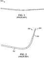
- Figure 1 shows a preformed 6F Hockey Stick (HS) 90 cm guide catheter 100, such as the ConcierGE® Guiding Catheter, available from Merit Medical Systems, Inc., which is advanced straight or over either a dilator or a guide wire from either the femoral or radial artery. Because the distal segment is highly flexible, the guide catheter may be safely advanced across the aortic valve into the left ventricle.
- the guide catheter 100 may be advanced into a femoral artery using any commercially available 6 Fr sheath. For radial access, a longer 25 cm sheath such as the Boston Scientific Super Sheath Catalog 16037-06B is preferred to avoid complications with radial artery spasm which occurs frequently in patients.
- HS 6F Hockey Stick
- Figure 2 shows the preformed 6 Fr HS 90 cm guide catheter 100 after a central straightening element, such as a dilator or wire, is removed and a trans-endocardial infusion catheter 200 with a highly flexible distal segment 202 with a length of at least 6 to 10 cm which reaches beyond the end of the guide catheter between 3.5 cm and 7 cm is inserted.
- the penetrating element is a helical needle 204 which may readily be rotated within the fixed guide and advanced in order to engage the catheter into the heart tissue.
- the highly flexible distal segment 202 on the trans-endocardial infusion catheter 200 does not straighten the highly flexible guide portion on the 6 Fr guide catheter enabling one to advance and rotate the fixed guide and then extend the helical needle 204 to the ventricular wall with the trans-endocardial delivery system to penetrate tissue and accomplish therapeutic or diagnostic delivery.
- the preformed guide shape will typically bend at least 90 degrees as there will be some slight straightening as the trans-endocardial infusion catheter is inserted due to the need for the guide distal end to be flexible.
- the trans-endocardial infusion catheter 200 is a BioCardia® helical needle model 953L catheter where the highly flexible region comprises a multifilar coil design but other flexible segments can be used in the present disclosure, e.g. the flexible segment could be made from an etched stainless steel tube such as shown in US Patent Nos. 5,228,441 ; 5,243,167 ; 5,322,064 ; 5,329,923 ; 5,334,145 ; 5,454,787 ; 5,477,856 ; and 5,685,868 , or form a wound ribbon structure.
- bending rigidity of such coil designs can be readily calculated by following validated closed form derivations for such complex geometries, as taught for example in Meagher, J., Altman, P.: Stresses from Flexure in Composite Helical Implantable Leads, Medical Engineering and Physics, Vol. 19, No. 7, pp 668-673, 1997 .
- Penetrating elements in different aspects of the present disclosure can be straight needles, curved needles, multi-pronged needles, and the like, as well being helical needles.
- a static sheath will typically be placed in the first 25 cm of the radial artery to reduce the impact of radial artery spasm on the procedure as well as the viability of the radial artery at the end of this procedure.
- a long 6F sheath may also be used with a 6 Fr guide to minimize the potential for a spasm to bind the inserted catheter and prevent completion of the procedure.
- a 25 cm 6 Fr introducer sheath and a 110 cm preformed 6 Fr guide catheter with a preformed 100 degree hockey stick angle are used to advance a 5.2 Fr trans-endocardial delivery catheter with a penetrating element mounted on the end of a highly flexible coil.
- These catheters may have two lumens which travel to the distal end, one of which discharges at the base of the penetrating element and one which passes through the penetrating element to discharge into the tissue penetrated, Further, this catheter system in its preferred embodiment has a helical needle at its distal tip, eliminating the need for perforation protection device.
- Alternative systems may utilize a steerable 6 Fr guide catheter with an outer diameter set to accommodate the 6 Fr sheath (6.4 Fr or smaller) and an inner diameter selected to accommodate a 4 Fr infusion catheter with an internal diameter of 3.9 Fr to 4.4 Fr.
- Such steerable guide catheters are commercially available, and a suitable steerable guide catheter is the Universal Deflectable Guide Catheter model #1066, manufactured by BioCardia, Inc., which has a 4.25 Fr internal lumen and a 6 French outer lumen.
- This approach has the same procedural advantages as the first embodiment disclosed here, but also benefits from the ability to deflect the distal end of the guide providing enhanced control options and also the ability to have greater back up support within the ventricle.
- This system may also be used with a 25 cm radial access sheath, but it is challenged by the ability to pass a larger diameter helical needle and thus a straight needle system with a passive perforation protection system is desired which will be described.
- This guide catheter allows entry with a 5 French steerable sheath (outer diameter 7.5 French) without an introducer sheath. Although there is added risk of radial artery spasm associated with the manipulation of the device within the artery, its steerable nature may significantly reduce the manipulations relative to that of a 6 Fr sheathless fixed guide which has a 7 Fr outer diameter. Both this sheathless guide and this steerable sheath system would benefit from a lubricious coating along the full length of the catheter shaft.
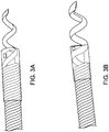
- Figures 3A and 3B shows the distal end of two trans-endocardial delivery catheters, each having two lumens: one lumen which is used for the delivery of contrast media and terminates at the base of the helical needle and one which goes all the way to the distal end of the helical needle.
- These needles are formed with a winding fixture that controls pitch and which has channel width specified to prevent flattening or excess "ovalization" (an unintended deformation of the cross-section from a circular geometry to an oval or similar non-circular geometry) of the circular needle cross-section.
- Needles are made from 304 stainless steel although other materials can also work.
- the needles are bonded into the dual lumen internal tubing that is covered with the distal multifilar coil, a mandrel is inserted into the contrast discharge lumen to protect its patency, and the helix is embedded in an epoxy resin, such as Loctite M-31CL where the needle is firmly secured to the distal highly flexible coil.
- the smaller diameter helical needle has an internal diameter of 0.008 inches and the larger diameter Helix has an internal diameter of 0.022 inches.
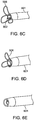
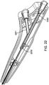
- Figures 4A and 4B show the distal end of a straight needle trans-endocardial catheter 402 system including a delivery catheter 404 that has a passive perforation protection system comprising a plurality (three) protective petals 406 surrounding the base of a straight injection needle 408.
- Figure 4A shows the system as it is being deployed, and Figure 4B shows it as it fully deployed.
- the systems of the present disclosure include the catheter of the present disclosure in combination with a guide catheter which could be anyone of a variety of conventional steerable or fixed guide catheters having a 5.2 Fr lumen or, in some cases a 4 Fr lumen.
- the system may optionally further include an introducer sleeve 817c, as shown Figure 8E , that may be a thin-walled slit tube of roughly three to ten centimeters in length that is advanced over the proximal shaft of the needle injection catheter to retract perforation protection device within a lumen of the sleeve.
- the catheter can then be advanced from the introducer sleeve into the guide catheter which will be used to deliver catheter after the introducer sleeve is removed.
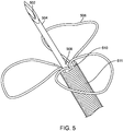
- Figure 5 shows the distal end of a trans-endocardial delivery system that is compatible with a 5.5 Fr lumen catheter introducer system 500 in which a straight needle 504 is mounted on the distal end of a flexible distal region 511 of a catheter body or shaft.
- a contrast port 510 is disposed at a base of petals 506 which are attached at a distal end of the region 511.
- the straight needle 504 may be a 27 Gage regular wall needle with a 0.008" inch lumen, and a 0.016" outer diameter and an exposed length of 0.160, 0.240, or 0.320.
- Tip 502 of needle 504 preferably has three facets, as shown, but could alternatively have one or two facets
- the penetration-limiting petals 506 may be formed from Nitinol® wire 0.0035 inches in diameter which has been served or covered with a coil of single filar 0.0015" diameter platinum iridium (Pt/Ir) 90/10) wire over the top for radiopacity.
- the flexible region of the catheter may be formed from five filar 0.008" wire coil 511 with an outer diameter of 0.063" with a pitch of 0.046" which extends ten centimeters from the more rigid catheter shaft.
- a dual lumen PEBAX 55D polymer tubing typically extends most or all of the length of the catheter.
- the base of the straight needle penetrating element 508 is inserted into and bonded to one of two lumens of the dual lumen tube.
- the stem or base of the penetration limiting/perforation protection structure is inserted 510 into the pentafilar coil 511 but will typically leave one of the internal lumens open to discharge a contrast medium when needed.
- a monolithic structure includes a plurality of petals which are partially or completely covered with the Pt/Ir wire coil.
- the wire covering facilitates assembly and improves longitudinal and radial spacing consistency. The covering may also enhance security of attachment. Assembly is performed by straightening the superelastic wire (which is preformed or set to have the three dimensional petal geometry illustrated herein), and the Pt/Ir coil is advanced over the straightened wire., The petal wire is then allowed to resume its relaxed multi-petal shape, and the penetration limiting/peroration protection structure is bonded with epoxy into the distal end of the catheter body or shaft as noted previously. Additionally or alternatively, the penetration limiting/perforation protection structure may also be attached using braze, solder, or by welding to the needle and/or the distal coil.
- the number of petals or leaflets is significant as it determines the number of individual wires that must anchored. Fewer leaflets thus occupy less of the available space inside the catheter but can result in thicker elements. Since bending stiffness tends to be a third order factor on diameter, doubling the diameter gives 8 times the stiffness. Thus anticipated that three loops allows more stiffness (thus resistance to puncture) than four, and perhaps more stable a geometry than two loops. The preferred embodiment has three loops but this should not limit the disclosure.
- the Nitinol® wire can also be selected from a range of sizes, typically 0.002 to 0.005 inches in diameter.
- the element of interest is the distal end of the main catheter body and not the "penetrating element” or needle.
- the force required to cause myocardial perforation / puncture is related to the presented cross sectional area of the tip of the catheter.
- the wire loop elements disclosed in this application effectively increase the apparent surface area of the distal end of the catheter body, thus increasing the force which would be required to cause myocardial perforation.
- Variable stiffness of the loops Since the root of each loop or petal near the distal end of the catheter body is the portion of the loop/petal which is the most resistant to being bent backwards (shortest lever arm to cause the bending), it is the most important to creating puncture resistance, and could be made stiffer than the portions of the loop further from the catheter tip, making the system more atraumatic, or more sensitive to contact with fine structures within the heart.
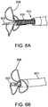
- Figure 6A through 6E show exemplary loop/petal structures which are suitable as the penetration limiting/perforation protection elements of the present disclosure and which readily collapses when deployed from or retracted into the distal end of a guide catheter.
- Figures 6A through 6E specifically show the penetration limiting/perforation protection system as the delivery catheter is being retracted back into the guide catheter:
- Figure 6A shows the distal region 511 of the infusion catheter extended from a guide catheter 601 with protective petals or leaflets 506 at full deployment.
- Figure 6B shows the leaflets or petals 506 fully deployed just before entering the guide catheter 601 as the delivery catheter is retracted into the guide catheter 601
- Figure 6C shows the leaflets or petals 506 starting to collapse around the needle 502 and into the guide catheter 601
- Figure 6D show the leaflets or petals 506 just prior to full capture by the guide catheter 601.
- Figure 6E shows the perforation protection system completely retracted and barely visible through the distal port of the guide catheter 601.
- This final position is referred to as the "garaged” state, when the delivery catheter is protected within the guide and the guide can be manipulated to target specific region within the ventricle.
- This protection device more than doubles the force to penetrate the heart tissue with a given 5 French straight needle catheter system.
- "Flower petals” passively expand/collapse when extended out from/drawn in to catheter, and when collapsed, the tips of the loops extend past the tip of a straight needle to inhibit gouging the ID of catheter, or tissue when partially retracted. In its deployed configuration, the penetration limiting/perforation protection system significantly reduces the risk of perforation with a straight needle system.
- a proximal portion 700 of a delivery catheter with two fluid lumens is shown in Figure 7 and includes a handle assembly 701 attached to a main catheter shaft 705 by a strain relief assembly 703.
- the catheter shaft 705 is a flexible, torquable composite conduit for the therapy and contrast delivery lumens.
- the strain relief assembly 703 serves as a protective transition between the catheter shaft and the handle assembly 701.
- FIG 8A panels 1-4 illustrates a penetration limiting/peroration protection including exemplary leaflet or petal elements.
- the leaflet elements 801 can be independent as shown above, or can have connected legs in what we would call a "monolithic structure" 806, e.g. all leaflets or petals may be formed from a single length of Nitinol® or other shape memory metal or polymer, where the length is further optionally connected at the ends to form a continuous structure with multiple loops.
- the legs can be of straight or have some other convoluted shape to improve bonding in an adhesive junction.
- the loops have several radii which aid in the collapse and/or expansion of the structure during sheathing and deployment.
- a major diameter 801a primarily defines the sheathed length relative to the needle which is covered and protected.
- the "folding blip" 801b is designed to prevent plastic strain upon sheathing where that segment of geometry is folded 180 degrees.
- the "root" radii 801d make sheathing easier, as the lever arm for folding down the leaflet is increased when this radius is increased.
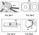
- Radiopacity can be provided by covering the leaflets with coiled platinum 801e as shown in Figure 8B (panel 1), or made from drawn filled tube (DFT) with a radiopaque center such as platinum 801f as shown Figure 8B (panel 2).
- Radiopacity coils can be attached with geometric binding, solder, or glue Panel 3 and 4 of Figure 8B show the loops are made by heat setting on a mandrel which has features to create the various chosen radii for example 809, 811, and 813.
- Figure 8C shows the dual lumen tube.
- the dual lumen 803b panel 2 has a channel for therapeutic and a channel for contrast.
- the therapeutic path is connected to the injection element 808 and delivers agents into the tissue.
- the contrast lumen opens at the tip of the shaft 805, and contrast is injected through it to assure correct positioning against the tissue surface.
- Options for the dual lumen include a non-round extrusion 803b with recesses for the legs of the leaflets optimizing cross sectional flow area, or a round extrusion could be blow molded to fit around the legs of the leaflets 803c (panel 3), again optimizing flow area, and also potentially improving leaflet security in bonding to the shaft.
- Tissue engagement indicators can provide additional feature/benefit of a radiopaque loop is the possibility of having it act as a tissue engagement indicator. Since the tips of the wire loops may be shaped as to "lead" the tip of the catheter by some distance, as the needle punctures the tissue and the distal end of the body of the catheter approaches the tissue surface, the tips of the loops bending back can be visualized under fluoroscopy.
- a potential added benefit of using the loops to indicate tissue engagement is the possibility of being able to eliminate the contrast lumen from the shaft, which could enable overall system size reduction or accommodate larger therapeutic lumens which enable the delivery of larger cells, cell aggregates, microspheres, Extra Cellular Matrix (ECM) slurries, particles, or higher viscosity therapeutic agents.
- the loops could be configured such that they form a generally conical shape, a flared bell shape like a trumpet, or closing bell shape like a toilet plunger.
- Figure 8D shows the distal flexible element and needle.
- the pentafilar coil 807 is a five element coil of 0.008" wire with a pitch of 0.046".
- This flexible element could optionally be comprised of a cut metal tube 807b ( Figure 8C ), which may have the advantages of thinner wall, and variable flexibility along its length, which if stiffer at the more proximal region, could improve column support thus improving ability to penetrate tough tissue at long extensions out of the steering delivery guiding catheter.
- the shaft typically comprises three main including the highly flexible distal segment 807, the main length of the shaft 815 and the strain relief segment 817. Note, the following items are also referenced in Figure 7 as the main shaft, 705, and strain relief, 703.
- the flexible element is as previously mentioned, may be fabricated of a five filar coil of stainless steel round wire 807.
- the main shaft is comprised of the outer jacket (braided polyamide) 815, and the inner dual lumen (Pebax) 803 ( Figure 8A ).
- the strain relief 817 contains an extension of the main shaft and dual lumen 815 and also has two segments of PEEK, one smaller 817a which fits inside the handle of the guiding catheter, and one larger 817b which can enter a rotating hemostasis valve (RHV) attached to the proximal luer of the guide catheter, but which does not enter the handle of the guide.
- RV rotating hemostasis valve
- the step at the end of the larger OD between the two strain relief sections is used as a reference point touched by the user to asses that the distal tip is just “garaged” within the guiding catheter while that junction is just at the proximal edge of the RHV.
- an introducer sheath can be slidably attached to the handle, shaft along the shaft, and cause the leaflets to fold forward for introduction into the guiding catheter.
- This element can become part of the strain relief, e.g. a snap fit design 817c (panel 1, Figure 8E ).
- the junction between the main shaft segment 815 and the distal flexible element 807 is formed with a thin walled hypotube or "bushing" bonded in place with cyanoacrylate adhesive.
- the junctions from the main shaft 815 to the strain relief 817 and the strain relief to the handle 819 may be made by epoxy adhesive, reference Figure 8D .
- Wire assemblies may be pre-tinned with Au-Sn solder, then soldered to a stainless steel needle & coil (or other flexible spring element) as a subassembly for simplification of manufacture.
- the radius of curvature of the wire as it leaves its attachment point should not be smaller than 10 times the wire diameter. Smallest recommended ratio is approximately 5.6:1, but that will likely plastically deform with use and have reduced fatigue life.
- Monolithic set of wire loops provide for ease of assembly, for consistency of longitudinal and radial spacing, and for increased security in attachment as opposed to single individual leaflets with straight "legs").
- Figure 8D shows the distal flexible element and needle in including a pentafiler coil 807 which is a five element coil of 0.008" wire with a pitch of 0.046".
- This flexible element could optionally be comprised of a cut metal tube 807b ( Figure 8C ), which may have the advantages of thinner wall, and variable flexibility along its length, which if stiffer at the more proximal region, could improve column support thus improving ability to penetrate tough tissue at long extensions out of the steering delivery guiding catheter.
- the shaft 807, 815, and 817 includes three main segments ( Figure 8D ): the highly flexible distal segment 807, the main length of the shaft 815, and the strain relief segment 817.
- the therapeutic lumen and contrast lumen will typically run uninterrupted the full length of catheter shaft.
- a junction between the pentafiler coil 807 and the polyamide jacket 815 is formed with an adhesive lap joint. This has been formed by Loctite 4014 bonding to either a thin walled 304 stainless bushing, not shown, with an ID/OD 0.038" / 0.042" x 0.3" long, or using the outer surface of the lumen assembly as the lap joint material.
- the main shaft outer jacket is a flexible torquable composite comprised of an 0.042" ID by 0.054" OD polyamide tube with 0.0015" wire braid (16 carrier) encapsulated in the wall 815.
- the strain relief assembly 703 serves as a protective transition between the catheter shaft and the handle assembly 701.
- the strain relief 81 contains an extension of the main shaft and dual lumen 815 and also has two segments of PEEK, one smaller (0.062" ID x 0.010" wall) 817a which fits inside the handle of the guiding catheter, and one larger (0.085" ID x 0.010" wall) 817b which can enter a rotating hemostasis valve (RHV) 1902 attached to the proximal luer of the guide catheter 1901, but which does not enter the handle of the guide.
- RV rotating hemostasis valve
- the step between the two OD's can be used as a reference point, touched by the user to asses that the distal tip is just "garaged” within the guiding catheter while that junction is just at the proximal edge of the RHV without having to expose the patient to increased radiation by using fluoroscopy to verify needle tip position.
- FIG 8F panels 1 and 2 shows that in cases where packing may be slightly too tight, the loops at the tip take up more space than the main body of the loop, so the tip positioning (in collapsed state) may be staggered axially (panel 2) either by staggering the root position, or by having differing loop sizes.
- the leaflets may be made so that they are self-reinforcing in a deployed configuration to reduce ease of fold back.
- One approach is for each loop threaded through an adjacent loop as shown.
- Another variation shown is a "steam colander" variation 801h (panels 3-6), with flexible sheets, or plates in curved triangular segments of conical section.
- the edges can have a folding or sliding interlocking mechanism to limit "splay" 801i.
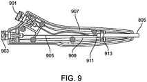
- Figure 9 is a cross sectional view of the handle assembly 701 from Figure 7 which can be standard for many of the dual lumen catheters here.
- the handle is an ergonomic catheter control feature containing the proximal ports of both the therapy and contrast lumens 901, 903.
- the catheter shaft 805 is secured directly to the strain relief assembly using epoxy adhesive such as Loctite M-06FL.
- a retaining block 913 is used to integrate the strain relief assembly and catheter shaft with the handle assembly using Loctite 4013 cyanoacrylate adhesive.
- the catheter shaft 911 terminates just proximal to the retaining block.
- the contrast lumen 907 is isolated and directed toward the contrast proximal luer 901.
- the therapy lumen is also isolated and a bushing, 909, is used to connect an extension tube, 905, to the therapy lumen in the main shaft.
- the proximal end of the extension tube is connected to the therapy proximal luer, 903.
- An alternative version of terminating the contrast and therapeutic lumens utilizes a "Y" adapter 2201, as illustrated in Figure 22 , allowing concentric therapy lumen 2202 and contrast lumen 2203 tubing configurations to be adhesively bonded directly to the "Y" adapter which terminates in luer-lock fitting for the therapeutic and contrast injection ports 901 & 903.
- Figures 10 through 12 show the distal tip of a three lumen catheter with a two lumen delivery needle 1130 a contrast lumen that terminates at the base of the needle, 1120, and the flexible distal element 1110 a pentifilar coil component. All of these features are secured together as the distal tip 1140 as shown using a two part epoxy as the bonding material.
- the preferred embodiment for the Helix Plus needle element is a helical shaped, dual stainless steel hypotube structure 1130.
- the proximal end of both hypotubes are bonded to independent tubes 1210, that serve as the axial conduit for fluid transport.
- Alternate embodiments include a lumen-in-lumen design 1150 which has been described previously by Miller in US Patent 7736346 .
- the helical needle, 1130 also serves as the distal electrode for electrophysiological sensing capabilities connected via electrode wire 12, and the exposed flexible distal element serves as the return electrode also connected by wire not shown.
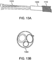
- Figure 13 shows a cross section of this tri-lumen configuration, 1340, that runs the distance of the device to the handle (electrode wires not shown).
- the distal and proximal electrode wires also run the length of the catheter with the tri-lumen bundle 1310 from their distal attachment points to the handle.
- Figure 14 shows the electrical connections of this system in more detail.
- the preferred design for the proximal sensing electrode to uses the distal flexible element formed of exposed pentafiler coil 1110 as the proximal electrode.
- An electrode wire 1410 is attached to the proximal end of the flexible element.
- One method of wire attachment is achieved by feeding the electrode wire through the attachment bushing 1405 winding the wire into the flexible element, 1440, and then soldered in place 1420.
- An alternate second electrode design uses a conductive proximal ring 1430 with the electrode wire being directed through the flexible element and attached to the ring.
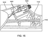
- Figure 15 shows the internal configuration for the Helix Plus handle assembly.
- the following describes the proximal termination within the handle 1610 for the three liquid carrying lumens and the two electrode wires.
- a multi-channel electrical connector 1630 is integrated into the handle with both electrodes 1620 being connected to the component within the handle.
- the three lumens used for the preferred tri-lumen design are all contained within the catheter shaft, 1030 continue through the strain relief assembly 1040 and exit within the handle assembly. The individual lumens are then directed to a proximal port in the handle 1140 where they exit and connect to standard luer fittings.
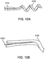
- Figures 16 and 17 shows a large bore needle based on 23 Ga tubing 1700, and a 27RW gage helical needle 1750.
- the needle is secured into the tip assembly by first using UV adhesive such as Loctite 3301 to bond it into the therapeutic lumen, then secondly embedding the needle and therapeutic lumen into the pentafiler coil using in an epoxy such as Loctite M-31CL to form a unibody structure 1720 that captures a loop of the Helix.
- UV adhesive such as Loctite 3301
- a ribbon of PTFE is fed between the coiled loops of the needle and into the contrast lumen (adjacent to, or concentrically around the therapeutic lumen) and this PTFE ribbon creates a flow path through the epoxy when it is removed after the epoxy has cured.
- This contrast lumen terminates at the distal end of the embedment at the base of the exposed needle 1730.
- the contrast lumen can be used to asses that the tip of the shaft 805 is positioned firmly against the myocardium when a needle is screwed into tissue. This assessment is performed by injecting contrast and observing on x-ray the resulting flow and how it pools and hangs with a boundary layer against the myocardium, or if it simply flows away like a puff of smoke with the flow of the cardiac pumping.
- Figure 18 shows an alternate design for distal perforation protection utilizing existing balloon technology when engaging heart tissue during trans-endocardial therapy delivery.
- Figure 18 shows three different views for the distally attached balloon feature; side view in the un-inflated state 1801 the side view in the inflated state 1802 and an isometric view of the inflated state 1803.
- a distally attached balloon feature provides a barrier at the proximal end of the needle 1010, as shown in 1802.
- the preferred deployment would involve inflating the balloon, using saline or contrast medium, after it is exposed from its guide catheter and before full engagement into the heart wall.
- fluid is injected in a port attached to the handle that runs through an internal lumen terminating below the surface of the balloon region in the distal end.
- a key advantage for this design is the ability to have a perforation protection system integrated into the distal end of the helical infusion catheter that is capable of function when rotated during standard use with a helical needle.
- Use of contrast as the balloon inflation medium provides the added benefit of a large radiopaque volume at the endocardial plane that can further assist with needle location and engagement assessment.
- a suitable balloon material, conforming to the catheter distal end in the un-inflated state 1810 is bonded at its distal and proximal ends to the base distal end structure.
- a port below the balloon structure connects via a suitable conduit to an inflation port in the handle.
- ID 0.008
- OD 0.016
- Material properties constraints and the desire to maintain the smallest profile were evaluated to optimize helix needle parameters of pitch, helix ID, helix OD, hypotube ID and hypo tube wall thickness.
- Various forming techniques were used to further optimize acceptably formed needles; for example, to control ovalization of the hypotube inside diameter. Mandrel sizes were varied to control material deformation while trying to maintain helix diameter within constraints.
- Other methods of controlling excessive ovalization included freezing water in the hypotube prior to coiling, annealing the hypotube prior to coiling and side wall support during winding.
- the resultant theoretical minimum mandrel diameter is 0.019in with a helix diameter of 0.069in.
- Experimental results varied from this theory as hypotubes tended to fail via ovalization versus tensile failure and the wound helix experienced "spring back" such that the final helix diameter was larger than theory.
- the mandrel used to make the 23 gage TW Large Bore needles was specified to have a minor diameter of 0.018 ⁇ 0.002" and produced a helix outer diameter ranging from 0.071 into 0.074in with an inner diameter of approximately 0.024in.
- the "spring back" and ovalization experienced by the helix is thusly documented and demonstrates that 23Ga TW helical needles wound on the ⁇ 0.018" mandrel can feasibly meet an outer diameter maximum specification.
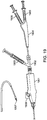
- Figure 19 shows an assembled system consisting of the following a Morph 895 deflectable tip catheter 1901 with an attached RHV (Merit MAP150) 1902, a syringe attached to the side port of the RHV 1903, a Helix catheter 1904, a syringe attached to the therapeutic port 1905, and a syringe attached to the contrast port 1906.
- a Helix needle at the tip 1907 is advanced and retracted through the guide to extend past the deflectable tip of the guide 1908 controlled by a guide deflection knob 1909.
- Figure 20 shows a Helix catheter consisting of the Helical needle 1907, the flexible distal element 2001, the braided shaft 2002, the two part strain relief 2003, the handle 2004, the therapeutic port 903 and the contrast port 901.
- Figures 21A through 21D show one method of Helix needle forming wrapping hypotube onto a mandrel 2001 which supports the sides of the tube to reduce ovalization.
- the needle can be formed with a variety of sized hypodermic tubing, The current commercially available iteration is made from 27GA RW 304 stainless steel. Large bore versions have been built using 24 and 23Ga tubing. Preferred stainless steel embodiments conform to ISO 9626 Annex A & E. Additional methods and materials to overcome limitations of material cold work limits may include forming directly to shape with electroforming of nickel or other material over a chemically removable wound mandrel such as aluminum or copper. After winding, the primary facet is cut 2002, then the secondary facets are added 2003.
- Additional option may include alternative tips such as closed form with side holes, trocar, or Tuohy tips.
- the final formed needle has a straight tail 2004 which is offset from center by an amount equal to the lumen offset in the shaft assembly, and which is bonded into the therapeutic lumen.
Claims (9)
- Ein Nadelinjektionskatheter, der Folgendes beinhaltet:einen Katheterkörper mit einem distalen Ende, einem proximalen Ende, einem steifen proximalen Anteil, einem biegsamen distalen Anteil (511) und einem Zuführlumen, das sich dadurch erstreckt;eine gerade Injektionsnadel (504), die sich koaxial aus einer distalen Spitze des biegsamen Anteils (511) des Katheterkörpers erstreckt; undeine Vielzahl von penetrationsbeschränkenden Elementen, die umlaufend um eine Basis der geraden Injektionsnadel herum positioniert sind und dazu ausgelegt sind, sich gegen einen Schaft der Nadel (504) radial nach innen zu falten, wenn sie in einem rohrförmigen Lumen eingezwängt sind, und sich radial nach außen zu erstrecken, wenn sie nicht eingezwängt sind, wobei die penetrationsbeschränkenden Elemente elastische Blütenblätter (506) beinhalten, die Basen aufweisen, die an der Basis der geraden Nadel an dem Katheterkörper befestigt sind, wobei die Blütenblätter (506) so gestaltet sind, dass sie sich von dem Katheterkörper nach außen biegen, wenn sie nicht eingezwängt sind, wobei die Blütenblätter (506) Drahtschlaufen sind, die in einer fortlaufenden Länge eines Formgedächtnisdrahts gefaltet sind, wobei ein Platindraht über den Formgedächtnisdraht gewickelt ist, um Strahlenundurchlässigkeit bereitzustellen.
- Katheter nach Anspruch 1, wobei der Katheter zwei bis sechs Blütenblätter (506) umfasst.
- Katheter nach einem der vorhergehenden Ansprüche, wobei der steife proximale Anteil des Katheterkörpers einen geflochtenen Polymerschlauch beinhaltet und der biegsame distale Anteil (511) des Katheterkörpers eine spiralförmige Metallspule beinhaltet.
- Katheter nach einem der vorhergehenden Ansprüche, wobei der Katheterkörper ein erstes Lumen zum Zuführen einer injizierbaren Zusammensetzung zu der Nadel und ein zweites Lumen zum Zuführen eines Kontrastmittels zu der Basis der Nadel aufweist.
- Katheter nach einem der vorhergehenden Ansprüche, der ferner einen Handgriff an dem proximalen Ende des Katheterkörpers aufweist.
- Katheter nach einem der vorhergehenden Ansprüche, wobei der Katheterkörper dazu ausgelegt ist, durch einen 2,15-mm(6,5-Fr)-Führungskatheter zugeführt zu werden.
- Ein Kathetersystem, das Folgendes beinhaltet:einen Nadelinjektionskatheter nach einem der vorhergehenden Ansprüche undeinen Führungskatheter (601) mit einem Lumen, das dazu ausgelegt ist, den Nadelinjektionskatheter aufzunehmen und die Vielzahl der penetrationsbeschränkenden Elemente radial einzuzwängen, wenn der Nadelinjektionskatheter sich darin befindet.
- Kathetersystem nach Anspruch 7, wobei der Führungskatheter (601) eine vorgeformte Biegung in der Nähe seines distalen Endes aufweist, sodass der Führungskatheter (601) gedreht werden kann, um das distale Ende mit einem Zielort auf einer Endokardwand auszurichten, wenn der Führungskatheter (601) sich in einer Herzkammer befindet.
- Kathetersystem nach Anspruch 7, wobei der Führungskatheter (601) ein ablenkbares distales Ende aufweist, um das distale Ende mit einem Zielort auf einer Endokardwand auszurichten, wenn der Führungskatheter sich in einer Herzkammer befindet.
Applications Claiming Priority (2)
| Application Number | Priority Date | Filing Date | Title |
|---|---|---|---|
| US201361884834P | 2013-09-30 | 2013-09-30 | |
| PCT/US2014/058439 WO2015048795A2 (en) | 2013-09-30 | 2014-09-30 | Radial and trans-endocardial delivery catheter |
Publications (3)
| Publication Number | Publication Date |
|---|---|
| EP3052176A2 EP3052176A2 (de) | 2016-08-10 |
| EP3052176A4 EP3052176A4 (de) | 2017-06-14 |
| EP3052176B1 true EP3052176B1 (de) | 2019-05-15 |
Family
ID=52744735
Family Applications (1)
| Application Number | Title | Priority Date | Filing Date |
|---|---|---|---|
| EP14848948.7A Active EP3052176B1 (de) | 2013-09-30 | 2014-09-30 | Radial- und transendokardialer freisetzungskatheter |
Country Status (5)
| Country | Link |
|---|---|
| US (4) | US10071226B2 (de) |
| EP (1) | EP3052176B1 (de) |
| JP (4) | JP6600301B2 (de) |
| CN (1) | CN105792877B (de) |
| WO (1) | WO2015048795A2 (de) |
Families Citing this family (15)
| Publication number | Priority date | Publication date | Assignee | Title |
|---|---|---|---|---|
| US10071226B2 (en) | 2013-09-30 | 2018-09-11 | Biocardia, Inc. | Radial and trans-endocardial delivery catheter |
| CN113521503A (zh) | 2014-12-01 | 2021-10-22 | 帕夫梅德有限公司 | 自锚固式导管及使用方法 |
| US20180153467A1 (en) * | 2015-06-03 | 2018-06-07 | Yoav Lichtenstein | Injecting and monitoring nervous tissue |
| CA3010700A1 (en) | 2016-01-07 | 2017-07-13 | Baylis Medical Company Inc. | Hybrid transseptal dilator and methods of using the same |
| CN106073947A (zh) * | 2016-08-29 | 2016-11-09 | 关丽鹃 | 心脏减容系统 |
| US11219744B2 (en) * | 2017-04-21 | 2022-01-11 | Medtronic Vascular, Inc. | Push wire for endoluminal medical device |
| CA3082159A1 (en) | 2017-11-30 | 2019-06-06 | Velano Vascular, Inc. | Stabilizing connector devices for vascular access and methods of using the same |
| JP7197559B2 (ja) * | 2018-03-02 | 2022-12-27 | テルモ株式会社 | ガイドワイヤおよび医療デバイス |
| CN114502229A (zh) * | 2019-10-15 | 2022-05-13 | 美敦力瓦斯科尔勒公司 | 用于球囊导管型装置的保护装置和方法 |
| US11826075B2 (en) * | 2020-04-07 | 2023-11-28 | Boston Scientific Medical Device Limited | Elongated medical assembly |
| CN114159675A (zh) * | 2020-09-11 | 2022-03-11 | 约翰·威廉·彼得·马尔斯曼 | 导丝套件 |
| CN116419719A (zh) * | 2020-11-12 | 2023-07-11 | 苏黎世医疗科技股份有限公司 | 手术设备、系统和制造手术设备的方法 |
| CN114159130B (zh) * | 2021-12-10 | 2023-12-29 | 郑由周 | 一种用于肠食管手术的辅助处理装置 |
| CN114366250B (zh) * | 2021-12-31 | 2023-09-05 | 杭州德柯医疗科技有限公司 | 套筒、注射装置、注射系统、消融装置及消融系统 |
| US20230310018A1 (en) * | 2022-03-28 | 2023-10-05 | Laminar, Inc. | Devices, systems, and methods for transseptal puncture |
Family Cites Families (46)
| Publication number | Priority date | Publication date | Assignee | Title |
|---|---|---|---|---|
| US5228441A (en) | 1991-02-15 | 1993-07-20 | Lundquist Ingemar H | Torquable catheter and method |
| US5329923A (en) | 1991-02-15 | 1994-07-19 | Lundquist Ingemar H | Torquable catheter |
| US5454787A (en) | 1991-02-15 | 1995-10-03 | Lundquist; Ingemar H. | Torquable tubular assembly and torquable catheter utilizing the same |
| AU660444B2 (en) | 1991-02-15 | 1995-06-29 | Ingemar H. Lundquist | Torquable catheter and method |
| US5183470A (en) * | 1991-03-04 | 1993-02-02 | International Medical, Inc. | Laparoscopic cholangiogram catheter and method of using same |
| US5243167A (en) | 1992-09-16 | 1993-09-07 | Ingemar H. Lundquist | Apparatus and method for manufacturing a slotted torque tube |
| US5334145A (en) | 1992-09-16 | 1994-08-02 | Lundquist Ingemar H | Torquable catheter |
| US5261889A (en) * | 1992-11-24 | 1993-11-16 | Boston Scientific Corporation | Injection therapy catheter |
| US5405376A (en) * | 1993-08-27 | 1995-04-11 | Medtronic, Inc. | Method and apparatus for ablation |
| US5571161A (en) * | 1995-04-12 | 1996-11-05 | Starksen; Niel F. | Apparatus and method for implanting electrical leads in the heart |
| US6723082B1 (en) * | 1995-05-10 | 2004-04-20 | Sam G. Payne | Delivery catheter system for heart chamber |
| US6322548B1 (en) | 1995-05-10 | 2001-11-27 | Eclipse Surgical Technologies | Delivery catheter system for heart chamber |
| US5728091A (en) * | 1995-06-07 | 1998-03-17 | Cardiogenesis Corporation | Optical fiber for myocardial channel formation |
| US7840264B1 (en) | 1996-08-19 | 2010-11-23 | Mr3 Medical, Llc | System and method for breaking reentry circuits by cooling cardiac tissue |
| US5971975A (en) | 1996-10-09 | 1999-10-26 | Target Therapeutics, Inc. | Guide catheter with enhanced guidewire tracking |
| US5851226A (en) * | 1996-10-22 | 1998-12-22 | Medtronic, Inc. | Temporary transvenous endocardial lead |
| US6416510B1 (en) | 1997-03-13 | 2002-07-09 | Biocardia, Inc. | Drug delivery catheters that attach to tissue and methods for their use |
| US6159195A (en) * | 1998-02-19 | 2000-12-12 | Percusurge, Inc. | Exchange catheter and method of use |
| US6102887A (en) * | 1998-08-11 | 2000-08-15 | Biocardia, Inc. | Catheter drug delivery system and method for use |
| US7972323B1 (en) * | 1998-10-02 | 2011-07-05 | Boston Scientific Scimed, Inc. | Steerable device for introducing diagnostic and therapeutic apparatus into the body |
| JP4297454B2 (ja) * | 1998-12-09 | 2009-07-15 | Hoya株式会社 | 内視鏡用穿刺具 |
| US20040122456A1 (en) | 2002-12-11 | 2004-06-24 | Saadat Vahid C. | Methods and apparatus for gastric reduction |
| US6582400B1 (en) * | 2000-10-24 | 2003-06-24 | Scimed Life Systems, Inc. | Variable tip catheter |
| US6511471B2 (en) * | 2000-12-22 | 2003-01-28 | Biocardia, Inc. | Drug delivery catheters that attach to tissue and methods for their use |
| US7717899B2 (en) * | 2002-01-28 | 2010-05-18 | Cardiac Pacemakers, Inc. | Inner and outer telescoping catheter delivery system |
| US7840261B2 (en) | 2002-06-05 | 2010-11-23 | Biocardia, Inc. | Catheter systems and methods for placing bi-ventricular pacing leads |
| WO2004045672A2 (en) * | 2002-11-15 | 2004-06-03 | The Government Of The United States As Represented By The Secretary Of The Department Of Health And Human Services | Variable curve catheter |
| US7998112B2 (en) * | 2003-09-30 | 2011-08-16 | Abbott Cardiovascular Systems Inc. | Deflectable catheter assembly and method of making same |
| US7402151B2 (en) | 2004-12-17 | 2008-07-22 | Biocardia, Inc. | Steerable guide catheters and methods for their use |
| WO2006074159A2 (en) * | 2005-01-03 | 2006-07-13 | Tricardia, Llc | Diffusion catheter |
| US8083722B2 (en) * | 2005-04-29 | 2011-12-27 | Warsaw Orthopedic, Inc | Instrumentation for injection of therapeutic fluid into joints |
| US7691086B2 (en) | 2005-06-14 | 2010-04-06 | Tengiz Tkebuchava | Catheter for introduction of medications to the tissues of a heart or other organ |
| US8123769B2 (en) * | 2005-08-12 | 2012-02-28 | Cook Medical Technologies Llc | Thrombus removal device |
| US7736346B2 (en) | 2005-10-18 | 2010-06-15 | Biocardia, Inc. | Bio-interventional therapeutic treatments for cardiovascular diseases |
| US20090227892A1 (en) * | 2006-05-11 | 2009-09-10 | Gabriele Krombach | Catheter Device for Percutaneous Procedures |
| US20070282257A1 (en) * | 2006-06-05 | 2007-12-06 | Schatz Richard A | Myocardial injector with balloon abutment |
| US7803136B2 (en) | 2006-06-05 | 2010-09-28 | Schatz Richard A | Myocardial injector |
| US8337518B2 (en) | 2006-12-20 | 2012-12-25 | Onset Medical Corporation | Expandable trans-septal sheath |
| US20090036832A1 (en) | 2007-08-03 | 2009-02-05 | Boston Scientific Scimed, Inc. | Guidewires and methods for manufacturing guidewires |
| WO2010011930A2 (en) * | 2008-07-24 | 2010-01-28 | Boston Scientific Scimed, Inc. | Various catheter devices for myocardial injections or other uses |
| US8361039B2 (en) | 2009-01-26 | 2013-01-29 | Schatz Richard A | Myocardial injector with spring loaded protective array |
| US20100274129A1 (en) * | 2009-04-24 | 2010-10-28 | Hooven Michael D | Apparatus And Methods for Separating Pericardial Tissue From The Epicardium of the Heart |
| JP2011083596A (ja) * | 2009-09-18 | 2011-04-28 | Terumo Corp | 冠動脈用カテーテル及びその係合方法 |
| WO2012061657A2 (en) | 2010-11-03 | 2012-05-10 | Biocardia, Inc. | Steerable endoluminal devices and methods |
| US20120165785A1 (en) * | 2010-12-23 | 2012-06-28 | Schatz Richard A | Catheter System for a Needle Injector with an Automatic Needle/Barrier Extension |
| US10071226B2 (en) | 2013-09-30 | 2018-09-11 | Biocardia, Inc. | Radial and trans-endocardial delivery catheter |
-
2014
- 2014-09-30 US US14/501,635 patent/US10071226B2/en active Active
- 2014-09-30 EP EP14848948.7A patent/EP3052176B1/de active Active
- 2014-09-30 CN CN201480065386.2A patent/CN105792877B/zh active Active
- 2014-09-30 JP JP2016518098A patent/JP6600301B2/ja active Active
- 2014-09-30 WO PCT/US2014/058439 patent/WO2015048795A2/en active Application Filing
-
2018
- 2018-08-09 US US16/059,480 patent/US10780248B2/en active Active
-
2019
- 2019-10-04 JP JP2019183455A patent/JP7282649B2/ja active Active
-
2020
- 2020-09-02 US US17/010,603 patent/US20200398029A1/en active Pending
-
2021
- 2021-08-26 JP JP2021137893A patent/JP2021184830A/ja not_active Withdrawn
-
2022
- 2022-06-02 US US17/831,189 patent/US20220305237A1/en active Pending
-
2023
- 2023-07-20 JP JP2023118177A patent/JP2023126613A/ja active Pending
Non-Patent Citations (1)
| Title |
|---|
| None * |
Also Published As
| Publication number | Publication date |
|---|---|
| CN105792877B (zh) | 2019-09-27 |
| CN105792877A (zh) | 2016-07-20 |
| JP2016537040A (ja) | 2016-12-01 |
| JP7282649B2 (ja) | 2023-05-29 |
| JP2023126613A (ja) | 2023-09-07 |
| EP3052176A4 (de) | 2017-06-14 |
| US20150231368A1 (en) | 2015-08-20 |
| US10071226B2 (en) | 2018-09-11 |
| US20200398029A1 (en) | 2020-12-24 |
| US20220305237A1 (en) | 2022-09-29 |
| JP2020018880A (ja) | 2020-02-06 |
| WO2015048795A2 (en) | 2015-04-02 |
| WO2015048795A3 (en) | 2015-05-21 |
| US20180344986A1 (en) | 2018-12-06 |
| EP3052176A2 (de) | 2016-08-10 |
| US10780248B2 (en) | 2020-09-22 |
| JP6600301B2 (ja) | 2019-10-30 |
| JP2021184830A (ja) | 2021-12-09 |
Similar Documents
| Publication | Publication Date | Title |
|---|---|---|
| US20220305237A1 (en) | Radial and trans-endocardial delivery catheter | |
| US20210290860A1 (en) | Expandable catheter system for fluid injection into and deep to the wall of a blood vessel | |
| US11389649B2 (en) | Delivery devices and methods for leadless cardiac devices | |
| CN111184554B (zh) | 导管装置 | |
| EP2018208B1 (de) | Transseptale nadelanordnungen und verfahren | |
| CN105030325B (zh) | 具有专用流体路径和针定心插入件的消融导管 | |
| EP2341974B1 (de) | Katheteranordnung | |
| US8118803B1 (en) | Deflectable catheter assembly | |
| WO2017087675A1 (en) | Delivery devices and methods for leadless cardiac devices | |
| EP3411113A1 (de) | Einführungssystem mit kraftsensor für drahtlose kardiale vorrichtung | |
| JP2006334399A (ja) | 遠位先端部方向付けシースを備えた操向性カテーテル | |
| JP2007520281A (ja) | 小血管用超音波カテーテル | |
| US10894162B2 (en) | Delivery devices and methods for leadless cardiac devices | |
| EP3370803B1 (de) | Injektionsvorrichtungen | |
| JP2016529028A (ja) | 成形可能な再入孔装置並びに関連するシステム及び方法 | |
| CN104042332B (zh) | 用于消融血管中组织层的带针头导管 | |
| EP3060287A1 (de) | Vorrichtung mit selektiv gekrümmtem distalen ende und verfahren zur verwendung |
Legal Events
| Date | Code | Title | Description |
|---|---|---|---|
| PUAI | Public reference made under article 153(3) epc to a published international application that has entered the european phase |
Free format text: ORIGINAL CODE: 0009012 |
|
| 17P | Request for examination filed |
Effective date: 20160420 |
|
| AK | Designated contracting states |
Kind code of ref document: A2 Designated state(s): AL AT BE BG CH CY CZ DE DK EE ES FI FR GB GR HR HU IE IS IT LI LT LU LV MC MK MT NL NO PL PT RO RS SE SI SK SM TR |
|
| AX | Request for extension of the european patent |
Extension state: BA ME |
|
| DAX | Request for extension of the european patent (deleted) | ||
| A4 | Supplementary search report drawn up and despatched |
Effective date: 20170511 |
|
| RIC1 | Information provided on ipc code assigned before grant |
Ipc: A61M 25/00 20060101AFI20170505BHEP |
|
| GRAP | Despatch of communication of intention to grant a patent |
Free format text: ORIGINAL CODE: EPIDOSNIGR1 |
|
| STAA | Information on the status of an ep patent application or granted ep patent |
Free format text: STATUS: GRANT OF PATENT IS INTENDED |
|
| RIC1 | Information provided on ipc code assigned before grant |
Ipc: A61M 25/06 20060101ALI20181107BHEP Ipc: A61M 25/00 20060101AFI20181107BHEP Ipc: A61M 25/09 20060101ALI20181107BHEP Ipc: A61B 17/00 20060101ALI20181107BHEP Ipc: A61B 90/00 20160101ALI20181107BHEP |
|
| INTG | Intention to grant announced |
Effective date: 20181206 |
|
| GRAS | Grant fee paid |
Free format text: ORIGINAL CODE: EPIDOSNIGR3 |
|
| GRAA | (expected) grant |
Free format text: ORIGINAL CODE: 0009210 |
|
| STAA | Information on the status of an ep patent application or granted ep patent |
Free format text: STATUS: THE PATENT HAS BEEN GRANTED |
|
| AK | Designated contracting states |
Kind code of ref document: B1 Designated state(s): AL AT BE BG CH CY CZ DE DK EE ES FI FR GB GR HR HU IE IS IT LI LT LU LV MC MK MT NL NO PL PT RO RS SE SI SK SM TR |
|
| REG | Reference to a national code |
Ref country code: CH Ref legal event code: EP |
|
| REG | Reference to a national code |
Ref country code: DE Ref legal event code: R096 Ref document number: 602014046983 Country of ref document: DE |
|
| REG | Reference to a national code |
Ref country code: IE Ref legal event code: FG4D |
|
| REG | Reference to a national code |
Ref country code: NL Ref legal event code: MP Effective date: 20190515 |
|
| REG | Reference to a national code |
Ref country code: LT Ref legal event code: MG4D |
|
| PG25 | Lapsed in a contracting state [announced via postgrant information from national office to epo] |
Ref country code: AL Free format text: LAPSE BECAUSE OF FAILURE TO SUBMIT A TRANSLATION OF THE DESCRIPTION OR TO PAY THE FEE WITHIN THE PRESCRIBED TIME-LIMIT Effective date: 20190515 Ref country code: PT Free format text: LAPSE BECAUSE OF FAILURE TO SUBMIT A TRANSLATION OF THE DESCRIPTION OR TO PAY THE FEE WITHIN THE PRESCRIBED TIME-LIMIT Effective date: 20190915 Ref country code: ES Free format text: LAPSE BECAUSE OF FAILURE TO SUBMIT A TRANSLATION OF THE DESCRIPTION OR TO PAY THE FEE WITHIN THE PRESCRIBED TIME-LIMIT Effective date: 20190515 Ref country code: LT Free format text: LAPSE BECAUSE OF FAILURE TO SUBMIT A TRANSLATION OF THE DESCRIPTION OR TO PAY THE FEE WITHIN THE PRESCRIBED TIME-LIMIT Effective date: 20190515 Ref country code: HR Free format text: LAPSE BECAUSE OF FAILURE TO SUBMIT A TRANSLATION OF THE DESCRIPTION OR TO PAY THE FEE WITHIN THE PRESCRIBED TIME-LIMIT Effective date: 20190515 Ref country code: NO Free format text: LAPSE BECAUSE OF FAILURE TO SUBMIT A TRANSLATION OF THE DESCRIPTION OR TO PAY THE FEE WITHIN THE PRESCRIBED TIME-LIMIT Effective date: 20190815 Ref country code: NL Free format text: LAPSE BECAUSE OF FAILURE TO SUBMIT A TRANSLATION OF THE DESCRIPTION OR TO PAY THE FEE WITHIN THE PRESCRIBED TIME-LIMIT Effective date: 20190515 Ref country code: SE Free format text: LAPSE BECAUSE OF FAILURE TO SUBMIT A TRANSLATION OF THE DESCRIPTION OR TO PAY THE FEE WITHIN THE PRESCRIBED TIME-LIMIT Effective date: 20190515 Ref country code: FI Free format text: LAPSE BECAUSE OF FAILURE TO SUBMIT A TRANSLATION OF THE DESCRIPTION OR TO PAY THE FEE WITHIN THE PRESCRIBED TIME-LIMIT Effective date: 20190515 |
|
| PG25 | Lapsed in a contracting state [announced via postgrant information from national office to epo] |
Ref country code: LV Free format text: LAPSE BECAUSE OF FAILURE TO SUBMIT A TRANSLATION OF THE DESCRIPTION OR TO PAY THE FEE WITHIN THE PRESCRIBED TIME-LIMIT Effective date: 20190515 Ref country code: RS Free format text: LAPSE BECAUSE OF FAILURE TO SUBMIT A TRANSLATION OF THE DESCRIPTION OR TO PAY THE FEE WITHIN THE PRESCRIBED TIME-LIMIT Effective date: 20190515 Ref country code: GR Free format text: LAPSE BECAUSE OF FAILURE TO SUBMIT A TRANSLATION OF THE DESCRIPTION OR TO PAY THE FEE WITHIN THE PRESCRIBED TIME-LIMIT Effective date: 20190816 Ref country code: BG Free format text: LAPSE BECAUSE OF FAILURE TO SUBMIT A TRANSLATION OF THE DESCRIPTION OR TO PAY THE FEE WITHIN THE PRESCRIBED TIME-LIMIT Effective date: 20190815 |
|
| REG | Reference to a national code |
Ref country code: AT Ref legal event code: MK05 Ref document number: 1132710 Country of ref document: AT Kind code of ref document: T Effective date: 20190515 |
|
| PG25 | Lapsed in a contracting state [announced via postgrant information from national office to epo] |
Ref country code: SK Free format text: LAPSE BECAUSE OF FAILURE TO SUBMIT A TRANSLATION OF THE DESCRIPTION OR TO PAY THE FEE WITHIN THE PRESCRIBED TIME-LIMIT Effective date: 20190515 Ref country code: DK Free format text: LAPSE BECAUSE OF FAILURE TO SUBMIT A TRANSLATION OF THE DESCRIPTION OR TO PAY THE FEE WITHIN THE PRESCRIBED TIME-LIMIT Effective date: 20190515 Ref country code: AT Free format text: LAPSE BECAUSE OF FAILURE TO SUBMIT A TRANSLATION OF THE DESCRIPTION OR TO PAY THE FEE WITHIN THE PRESCRIBED TIME-LIMIT Effective date: 20190515 Ref country code: RO Free format text: LAPSE BECAUSE OF FAILURE TO SUBMIT A TRANSLATION OF THE DESCRIPTION OR TO PAY THE FEE WITHIN THE PRESCRIBED TIME-LIMIT Effective date: 20190515 Ref country code: CZ Free format text: LAPSE BECAUSE OF FAILURE TO SUBMIT A TRANSLATION OF THE DESCRIPTION OR TO PAY THE FEE WITHIN THE PRESCRIBED TIME-LIMIT Effective date: 20190515 Ref country code: EE Free format text: LAPSE BECAUSE OF FAILURE TO SUBMIT A TRANSLATION OF THE DESCRIPTION OR TO PAY THE FEE WITHIN THE PRESCRIBED TIME-LIMIT Effective date: 20190515 |
|
| REG | Reference to a national code |
Ref country code: DE Ref legal event code: R097 Ref document number: 602014046983 Country of ref document: DE |
|
| PG25 | Lapsed in a contracting state [announced via postgrant information from national office to epo] |
Ref country code: SM Free format text: LAPSE BECAUSE OF FAILURE TO SUBMIT A TRANSLATION OF THE DESCRIPTION OR TO PAY THE FEE WITHIN THE PRESCRIBED TIME-LIMIT Effective date: 20190515 Ref country code: IT Free format text: LAPSE BECAUSE OF FAILURE TO SUBMIT A TRANSLATION OF THE DESCRIPTION OR TO PAY THE FEE WITHIN THE PRESCRIBED TIME-LIMIT Effective date: 20190515 |
|
| PLBE | No opposition filed within time limit |
Free format text: ORIGINAL CODE: 0009261 |
|
| STAA | Information on the status of an ep patent application or granted ep patent |
Free format text: STATUS: NO OPPOSITION FILED WITHIN TIME LIMIT |
|
| PG25 | Lapsed in a contracting state [announced via postgrant information from national office to epo] |
Ref country code: TR Free format text: LAPSE BECAUSE OF FAILURE TO SUBMIT A TRANSLATION OF THE DESCRIPTION OR TO PAY THE FEE WITHIN THE PRESCRIBED TIME-LIMIT Effective date: 20190515 |
|
| 26N | No opposition filed |
Effective date: 20200218 |
|
| PG25 | Lapsed in a contracting state [announced via postgrant information from national office to epo] |
Ref country code: PL Free format text: LAPSE BECAUSE OF FAILURE TO SUBMIT A TRANSLATION OF THE DESCRIPTION OR TO PAY THE FEE WITHIN THE PRESCRIBED TIME-LIMIT Effective date: 20190515 |
|
| PG25 | Lapsed in a contracting state [announced via postgrant information from national office to epo] |
Ref country code: MC Free format text: LAPSE BECAUSE OF FAILURE TO SUBMIT A TRANSLATION OF THE DESCRIPTION OR TO PAY THE FEE WITHIN THE PRESCRIBED TIME-LIMIT Effective date: 20190515 Ref country code: SI Free format text: LAPSE BECAUSE OF FAILURE TO SUBMIT A TRANSLATION OF THE DESCRIPTION OR TO PAY THE FEE WITHIN THE PRESCRIBED TIME-LIMIT Effective date: 20190515 |
|
| REG | Reference to a national code |
Ref country code: CH Ref legal event code: PL |
|
| PG25 | Lapsed in a contracting state [announced via postgrant information from national office to epo] |
Ref country code: IE Free format text: LAPSE BECAUSE OF NON-PAYMENT OF DUE FEES Effective date: 20190930 Ref country code: LU Free format text: LAPSE BECAUSE OF NON-PAYMENT OF DUE FEES Effective date: 20190930 Ref country code: CH Free format text: LAPSE BECAUSE OF NON-PAYMENT OF DUE FEES Effective date: 20190930 Ref country code: LI Free format text: LAPSE BECAUSE OF NON-PAYMENT OF DUE FEES Effective date: 20190930 |
|
| REG | Reference to a national code |
Ref country code: BE Ref legal event code: MM Effective date: 20190930 |
|
| PG25 | Lapsed in a contracting state [announced via postgrant information from national office to epo] |
Ref country code: BE Free format text: LAPSE BECAUSE OF NON-PAYMENT OF DUE FEES Effective date: 20190930 |
|
| PG25 | Lapsed in a contracting state [announced via postgrant information from national office to epo] |
Ref country code: CY Free format text: LAPSE BECAUSE OF FAILURE TO SUBMIT A TRANSLATION OF THE DESCRIPTION OR TO PAY THE FEE WITHIN THE PRESCRIBED TIME-LIMIT Effective date: 20190515 |
|
| PG25 | Lapsed in a contracting state [announced via postgrant information from national office to epo] |
Ref country code: IS Free format text: LAPSE BECAUSE OF FAILURE TO SUBMIT A TRANSLATION OF THE DESCRIPTION OR TO PAY THE FEE WITHIN THE PRESCRIBED TIME-LIMIT Effective date: 20190915 |
|
| PG25 | Lapsed in a contracting state [announced via postgrant information from national office to epo] |
Ref country code: MT Free format text: LAPSE BECAUSE OF FAILURE TO SUBMIT A TRANSLATION OF THE DESCRIPTION OR TO PAY THE FEE WITHIN THE PRESCRIBED TIME-LIMIT Effective date: 20190515 Ref country code: HU Free format text: LAPSE BECAUSE OF FAILURE TO SUBMIT A TRANSLATION OF THE DESCRIPTION OR TO PAY THE FEE WITHIN THE PRESCRIBED TIME-LIMIT; INVALID AB INITIO Effective date: 20140930 |
|
| PG25 | Lapsed in a contracting state [announced via postgrant information from national office to epo] |
Ref country code: MK Free format text: LAPSE BECAUSE OF FAILURE TO SUBMIT A TRANSLATION OF THE DESCRIPTION OR TO PAY THE FEE WITHIN THE PRESCRIBED TIME-LIMIT Effective date: 20190515 |
|
| P01 | Opt-out of the competence of the unified patent court (upc) registered |
Effective date: 20230520 |
|
| PGFP | Annual fee paid to national office [announced via postgrant information from national office to epo] |
Ref country code: GB Payment date: 20230927 Year of fee payment: 10 |
|
| PGFP | Annual fee paid to national office [announced via postgrant information from national office to epo] |
Ref country code: FR Payment date: 20230925 Year of fee payment: 10 Ref country code: DE Payment date: 20230927 Year of fee payment: 10 |