EP3051904B1 - Base station, mobile station, reference-signal transmission method, and channel-quality measurement method - Google Patents
Base station, mobile station, reference-signal transmission method, and channel-quality measurement method Download PDFInfo
- Publication number
- EP3051904B1 EP3051904B1 EP14848382.9A EP14848382A EP3051904B1 EP 3051904 B1 EP3051904 B1 EP 3051904B1 EP 14848382 A EP14848382 A EP 14848382A EP 3051904 B1 EP3051904 B1 EP 3051904B1
- Authority
- EP
- European Patent Office
- Prior art keywords
- csi
- mapping
- antenna ports
- channel state
- state information
- Prior art date
- Legal status (The legal status is an assumption and is not a legal conclusion. Google has not performed a legal analysis and makes no representation as to the accuracy of the status listed.)
- Active
Links
Images


Classifications
-
- H—ELECTRICITY
- H04—ELECTRIC COMMUNICATION TECHNIQUE
- H04W—WIRELESS COMMUNICATION NETWORKS
- H04W24/00—Supervisory, monitoring or testing arrangements
- H04W24/10—Scheduling measurement reports ; Arrangements for measurement reports
-
- H—ELECTRICITY
- H04—ELECTRIC COMMUNICATION TECHNIQUE
- H04B—TRANSMISSION
- H04B7/00—Radio transmission systems, i.e. using radiation field
- H04B7/02—Diversity systems; Multi-antenna system, i.e. transmission or reception using multiple antennas
- H04B7/04—Diversity systems; Multi-antenna system, i.e. transmission or reception using multiple antennas using two or more spaced independent antennas
- H04B7/06—Diversity systems; Multi-antenna system, i.e. transmission or reception using multiple antennas using two or more spaced independent antennas at the transmitting station
- H04B7/0613—Diversity systems; Multi-antenna system, i.e. transmission or reception using multiple antennas using two or more spaced independent antennas at the transmitting station using simultaneous transmission
- H04B7/0615—Diversity systems; Multi-antenna system, i.e. transmission or reception using multiple antennas using two or more spaced independent antennas at the transmitting station using simultaneous transmission of weighted versions of same signal
- H04B7/0619—Diversity systems; Multi-antenna system, i.e. transmission or reception using multiple antennas using two or more spaced independent antennas at the transmitting station using simultaneous transmission of weighted versions of same signal using feedback from receiving side
- H04B7/0621—Feedback content
- H04B7/0626—Channel coefficients, e.g. channel state information [CSI]
-
- H—ELECTRICITY
- H04—ELECTRIC COMMUNICATION TECHNIQUE
- H04B—TRANSMISSION
- H04B7/00—Radio transmission systems, i.e. using radiation field
- H04B7/02—Diversity systems; Multi-antenna system, i.e. transmission or reception using multiple antennas
- H04B7/04—Diversity systems; Multi-antenna system, i.e. transmission or reception using multiple antennas using two or more spaced independent antennas
- H04B7/0413—MIMO systems
- H04B7/0417—Feedback systems
-
- H—ELECTRICITY
- H04—ELECTRIC COMMUNICATION TECHNIQUE
- H04B—TRANSMISSION
- H04B7/00—Radio transmission systems, i.e. using radiation field
- H04B7/02—Diversity systems; Multi-antenna system, i.e. transmission or reception using multiple antennas
- H04B7/04—Diversity systems; Multi-antenna system, i.e. transmission or reception using multiple antennas using two or more spaced independent antennas
- H04B7/06—Diversity systems; Multi-antenna system, i.e. transmission or reception using multiple antennas using two or more spaced independent antennas at the transmitting station
- H04B7/0613—Diversity systems; Multi-antenna system, i.e. transmission or reception using multiple antennas using two or more spaced independent antennas at the transmitting station using simultaneous transmission
- H04B7/0684—Diversity systems; Multi-antenna system, i.e. transmission or reception using multiple antennas using two or more spaced independent antennas at the transmitting station using simultaneous transmission using different training sequences per antenna
-
- H—ELECTRICITY
- H04—ELECTRIC COMMUNICATION TECHNIQUE
- H04L—TRANSMISSION OF DIGITAL INFORMATION, e.g. TELEGRAPHIC COMMUNICATION
- H04L5/00—Arrangements affording multiple use of the transmission path
- H04L5/003—Arrangements for allocating sub-channels of the transmission path
- H04L5/0048—Allocation of pilot signals, i.e. of signals known to the receiver
-
- H—ELECTRICITY
- H04—ELECTRIC COMMUNICATION TECHNIQUE
- H04L—TRANSMISSION OF DIGITAL INFORMATION, e.g. TELEGRAPHIC COMMUNICATION
- H04L5/00—Arrangements affording multiple use of the transmission path
- H04L5/003—Arrangements for allocating sub-channels of the transmission path
- H04L5/0053—Allocation of signalling, i.e. of overhead other than pilot signals
- H04L5/0057—Physical resource allocation for CQI
-
- H—ELECTRICITY
- H04—ELECTRIC COMMUNICATION TECHNIQUE
- H04W—WIRELESS COMMUNICATION NETWORKS
- H04W16/00—Network planning, e.g. coverage or traffic planning tools; Network deployment, e.g. resource partitioning or cells structures
- H04W16/24—Cell structures
- H04W16/28—Cell structures using beam steering
-
- H—ELECTRICITY
- H04—ELECTRIC COMMUNICATION TECHNIQUE
- H04W—WIRELESS COMMUNICATION NETWORKS
- H04W72/00—Local resource management
- H04W72/12—Wireless traffic scheduling
- H04W72/1263—Mapping of traffic onto schedule, e.g. scheduled allocation or multiplexing of flows
-
- H—ELECTRICITY
- H04—ELECTRIC COMMUNICATION TECHNIQUE
- H04L—TRANSMISSION OF DIGITAL INFORMATION, e.g. TELEGRAPHIC COMMUNICATION
- H04L5/00—Arrangements affording multiple use of the transmission path
- H04L5/0001—Arrangements for dividing the transmission path
- H04L5/0014—Three-dimensional division
- H04L5/0023—Time-frequency-space
Definitions
- the present invention relates to a base station, a mobile station, a reference signal transmission method, and a channel quality measurement method.
- three-dimensional MIMO (3D-MIMO: Three Dimensional Multiple Input Multiple Output) has been studied such that multiple antenna elements, which are two-dimensionally arranged in the vertical direction and horizontal direction, are installed in a base station, and a beam is formed in the vertical direction, in addition to the horizontal direction. It can be expected that system characteristics can be enhanced by forming a beam in the vertical direction and horizontal direction.
- the 3D-MIMO for a case where the number of the antenna ports is less than or equal to 8 is referred to as vertical beam forming
- the 3D-MIMO for a case where the number of the antenna ports is greater than 8 is referred to as Full Dimension-MIMO (FD-MIMO).
- FD-MIMO is often referred to as "Massive MIMO.”
- Massive MIMO can improve frequency utilization efficiency by forming a sharp beam by using a great number of antenna elements of a base station.
- CSI-RS Reference Signal for CSI measurement
- CSI Channel State Information
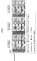
- FIG. 1 shows an example of mapping of the CSI-RS for the case where the number of the antenna ports is less than or equal to 8.
- RE Resource Element
- RB Resource Block
- the CSI-RS is transmitted with a transmission period of 5, 10, 20, 40, or 80 milliseconds. The transmission period of the CSI-RS is set by Radio Resource Control (RRC) signaling.
- RRC Radio Resource Control
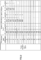
- FIG. 2 shows an example of a table that is used for specifying a resource configuration of the CSI-RS.
- CSI-RS mapping For example, for a case where the number of the antenna ports is 2, there are twenty types of CSI-RS mapping, which are shown in (A) of FIG. 1 .
- To signal to a mobile station, which one of the twenty types of the mapping is to be used, one of the indexes from 0 to 19 (CSI reference signal configuration) in the table of FIG. 2 is used.
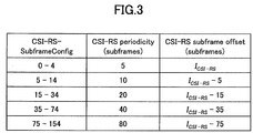
- FIG. 3 shows an example of a table that is used for specifying a subframe configuration of the CSI-RS.
- the CSI-RS that is specified by using the table of FIG. 2 is transmitted with a period of 5, 10, 20, 40, or 80 milliseconds, while the CSI-RS is multiplexed in the subframe.
- the CSI-RS-SubframeConfig one of the indexes from 0 to 154 in the table of FIG. 3 (CSI RS-SubframeConfig) is signaled to the mobile station.
- US 2012/028 7875 A1 refers to providing channel state information reference signals in a wireless communication system supporting multiple antennas.
- Information on different channel state information reference signal configurations is transmitted to the mobile station.
- the channel state information reference signals are mapped to resource elements based on the configurations.
- a subframe mapped with the channel state information reference signals is transmitted to the mobile station. Examples of the different channel state information reference signal configurations are shown.
- One of the channel state information reference signal patterns is available for any downlink subframe.
- Section 5.1 refers to multiple CSI-RS configurations for measuring a 3D channel and feeding back a pair of CSIs, including one corresponding to the rows of antenna elements and one corresponding to the columns of antenna elements.
- Figures 1 and 2 show an example of mappings in the horizontal and vertical direction.
- the CSI-RS that is specified by Release 10 of the 3GPP standard supports up to eight antenna ports. However, in order to implement channel quality measurement for the FD-MIMO, it may be required to support an extended number of the antenna ports, such as 16, 32, 64, and so forth.
- An object of the present invention is to achieve CSI-RS configurations that can support an extended number of the antenna ports.
- CSI-RS configurations can be achieved that can support an extended number of the antenna ports.
- a base station (eNB: evolved Node B) having a plurality of antenna ports, more specifically, a base station for implementing a CSI-RS configuration that can support an extended number of antenna ports (a number of antenna ports greater than 8) is described.
- a mobile station (UE: User Equipment) that communicates with a base station having a plurality of antenna ports, more specifically, a mobile station for implementing channel quality measurement by using the CSI-RS that can support the extended number of antenna ports is described.
- the CSI-RS is reference signals that are used for measuring channel state information (CSI), such as a Channel Quality Indicator (CQI), a Precoding Matrix Indicator (PMI), and a Rank Indicator (RI).
- CSI channel state information
- CQI Channel Quality Indicator
- PMI Precoding Matrix Indicator
- RI Rank Indicator
- an antenna port is a set of one or more antenna elements for transmitting reference signals. There are cases where one antenna port corresponds to one antenna element, and there are cases where one antenna port corresponds to a plurality of antenna elements.
- the following design concept is considered.
- configurations of the CSI-RS that can support the extended number of the antenna ports can be achieved by any of the following methods.
- the mapping of the CSI-RS for the eight antenna ports (cf. (C) of FIG. 1 ) is used as reference mapping.
- the antenna port numbers from 0 to 15 are divided into the antenna port numbers from 0 to 7 and the antenna port numbers from 8 to 15.
- mapping of the CSI-RS for the antenna port numbers from 0 to 7 for the CSI-RS for the antenna port numbers from 0 to 7, or for the CSI-RS for the antenna port numbers from 8 to 15 mapping of the CSI-RS corresponding to the extended number of the antenna ports is generated. It can be defined on a system how to allocate a group of antenna ports to a subframe or to a resource block.
- a base station signals information indicating the generated mapping to a mobile station. The base station also multiplexes the CSI-RS in a resource block in accordance with the generated mapping.
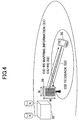
- FIG. 4 is a schematic diagram showing a radio communication system according to an embodiment of the present invention.
- the radio communication system includes a macro base station 10 that covers a wide range; a FD-MIMO station 20 that is located in the area of or in the vicinity of the area of the macro base station 10, and that includes two-dimensionally arranged antenna elements; and a mobile station 30. It is assumed that the FD-MIMO station 20 includes more than eight antenna elements. The more than eight antenna elements are classified as more than 8 antenna ports. As described above, one antenna element may correspond to one antenna port, and a plurality of antenna elements may correspond to one antenna port. In FIG. 4 , the macro base station 10 and the FD-MIMO station 20 are separately arranged.
- the macro base station 10 may be configured as an FD-MIMO station having more than eight antenna elements. Further, it is described that the FD-MIMO station 20 includes two-dimensionally arranged antenna elements. However, the FD-MIMO station 20 may include one-dimensionally arranged antenna elements or three-dimensionally arranged antenna elements.
- the FD-MIMO station 20 generates mapping of a CSI-RS corresponding to the extended number of the antenna ports, and the FD-MIMO station 20 transmits the mapping information of the CSI-RS to the mobile station 30 (S1). For example, the FD-MIMO station 20 may transmit, to the mobile station 30, a number of the antenna ports; and an index indicating the mapping of the CSI-RS (CSI reference signal configuration). The example of the mapping is described below by referring to FIG. 5 . Further, the FD-MIMO station 20 multiplexes the CSI-RS in one or more resource elements in a resource block in accordance with the generated mapping, and the FD-MIMO station 20 transmits the CSI-RS to the mobile station 30 (S2).
- the mobile station 30 can extract the CSI-RS in accordance with the mapping information of the CSI-RS.
- the mobile station 30 measures channel quality by using the CSI-RS; generates the CSI; and transmits the CSI to the FD-MIMO station 20 (S3).
- mapping of the CSI-RS for a case where the number of the antenna ports is 16 is shown in (A) of FIG. 5 .
- the mapping of the CSI-RS is generated similar to the case where the number of antenna ports is 8.
- the CSI-RS for antenna port numbers (0,1) is continuously allocated in a single subcarrier
- the CSI-RS for antenna port numbers (4, 5) is continuously allocated in the next subcarrier.
- the CSI-RS for antenna port numbers (2, 3) is continuously allocated in a single subcarrier
- the CSI-RS for antenna port numbers (6, 7) is continuously allocated in the next subcarrier.
- the above-described allocation of the CSI-RS of the antenna port numbers (0, 1, 4, 5) and the numbers (2, 3, 6, 7) is extended for the CSI-RS for the antenna port numbers from 8 to 15.
- the CSI-RS for the antenna port numbers (8, 9) is continuously allocated at symbols that are next to the CSI-RS for the antenna port numbers (0, 1).
- the CSI-RS for the antenna port numbers (10, 11) is continuously allocated in a subcarrier that is next to the CSI-RS for the antenna port numbers (8, 9).
- the CSI-RS for the antenna port numbers (12, 13) is continuously allocated at symbols that are next to the CSI-RS for the antenna port numbers (2, 3).
- the CSI-RS for the antenna port numbers (14, 15) is continuously allocated in a subcarrier that is next to the CSI-RS for the antenna port numbers (12, 13).
- mapping of the CSI-RS for the case where the number of the antenna ports is 16 is not limited to the mapping shown in (A) of FIG. 5 .
- the CSI-RS may be allocated as shown in (B) of FIG. 5 .
- the allocation of the CSI-RS for the antenna port numbers (0, 1, 4, 5) and (2, 3, 6, 7) for the case where the number of the antenna ports is 8 is extended for the CSI-RS for the antenna port numbers from 8 to 31.
- the CSI-RS for the antenna port numbers from 0 to 15 is allocated. Then, the CSI-RS for the antenna port numbers (16, 17) is continuously allocated in a single subcarrier at symbol positions that are the same as the symbol positions of the CSI-RS for the antenna port numbers (0, 1), and the CSI-RS for the antenna port numbers (20, 21) is continuously allocated in the next subcarrier. Further, the CSI-RS for the antenna port numbers (24, 25) is continuously allocated at symbols that are next to the CSI-RS for the antenna port number (16, 17).
- the CSI-RS for the antenna port numbers (26, 27) is continuously allocated in the subcarrier that is next to the CSI-RS for the antenna port numbers (24, 25).
- the CSI-RS for the antenna port numbers (18, 19) is continuously allocated in a single subcarrier at symbol positions that are the same as the symbol positions of the CSI-RS for the antenna port numbers (0, 1), and the CSI-RS for the antenna port numbers (22, 23) is continuously allocated in the next subcarrier.
- the CSI-RS for the antenna port numbers (28, 29) is continuously allocated at symbols that are next to the CSI-RS for the antenna port number (18, 19).
- the CSI-RS for the antenna port numbers (30, 31) is continuously allocated in the subcarrier that is next to the CSI-RS for the antenna port numbers (28, 29).
- mapping of the CSI-RS for the case where the number of the antenna ports is 32 is not limited to the mapping shown in (B) of FIG. 5 .
- the CSI-RS may be allocated at different resource elements.
- the CSI-RS is allocated to resource elements for a Physical Downlink Shared Channel (PDSCH).
- PDSCH Physical Downlink Shared Channel
- the CSI-RS may be mapped so that the resource elements for the CSI-RS for the antenna port numbers from 0 to 7, which are shown in FIG. 1 , are to be used.
- An example of the mapping of the CSI-RS for a case where the number of the antenna ports is 32 is shown in (D) of FIG. 5 .
- the overhead of the CSI-RS increases, as the number of the antenna ports increases. For example, for a case where the number of the antenna ports is 64, the overhead of a Physical Uplink Control Channel (PUCCH), a Cell-specific Reference Signal (CRS), a Demodulation Reference Signal (DM-RS), and the CSI-RS can be 83%. In this case, there is almost no region for transmitting a data signal in the resource block in which the CSI-RS is included. Thus, mapping of the CSI-RS may be defined with an assumption that no data signal is to be transmitted in the resource block.
- PUCCH Physical Uplink Control Channel
- CRS Cell-specific Reference Signal
- DM-RS Demodulation Reference Signal
- the CSI-RS may be allocated to resource elements to which the DM-RS is to be allocated (DMRS (Rel-9/10) in FIG. 1 ); resource elements to which the CRS for antenna portion numbers 3 and 4 is to be allocated (CRS port #3, 4 in FIG. 1 ); the DM-RS for Release 8 (DMRS (Rel-8) port #5 in FIG. 1 ), and so forth.
- DMRS Resource elements to which the DM-RS is to be allocated
- CRS port #3, 4 in FIG. 1 resource elements to which the CRS for antenna portion numbers 3 and 4 is to be allocated
- DM-RS for Release 8 DMRS (Rel-8) port #5 in FIG. 1
- the CSI-RS is multiplexed in the resource elements by Frequency Division Multiplexing (FDM) and Time Division Multiplexing (TDM).
- the CSI-RS may be multiplexed by combining these with Code Division Multiplexing (CDM).
- CDM Code Division Multiplexing
- the CSI-RS for an antenna port may be code division multiplexed with the CSI-RS for another antenna port, and these may be multiplexed in resource elements that are reserved for the CSI-RS.
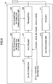
- FIG. 6 shows a block diagram of the base station 20 according to the embodiment of the present invention.
- the base station 20 includes a CSI-RS generator 201; a CSI-RS mapping information storage unit 203; a CSI-RS mapping information communication unit 205; a multiplexer 207; a transmitter 209; a receiver 211; and a CSI processing unit 213.
- the CSI-RS generator 201 generates reference signals for measuring channel state information (CSI-RS).
- the CSI-RS mapping information storage unit 203 stores mapping information that indicates, in which resource elements in a resource block, the CSI-RS is to be multiplexed.
- the CSI-RS mapping information storage unit 203 stores, for example, the mapping information, such as shown in (A) of FIG. 5 through (D) of FIG. 5 .
- the CSI-RS mapping information communication unit 205 signals, to a mobile station, information indicating the mapping of the CSI-RS. For example, for a case where two types of mapping information are defined on a system, such as the case of the 16-antenna ports of (A) of FIG. 5 , the CSI-RS mapping information communication unit 205 may signal, to a mobile station, information indicating antenna port numbers and indexes indicating the mappings of the CSI-RS (CSI reference signal configurations).
- the multiplexer 207 multiplexes the CSI-RS in resource elements in a resource block, in accordance with the mapping information that is stored in the CSI-RS mapping information storage unit 203. Additionally, data, control information, and so forth are multiplexed in the resource elements in the resource block, after encoding, rate matching, modulation, and the like are applied to them.
- the multiplexer 207 can multiplex the PDSCH, while avoiding the CSI-RS.
- rate matching unit not depicted
- the multiplexer 207 may apply puncturing.
- the transmitter 209 transmits a signal to a mobile station. Especially, the transmitter 209 transmits, to a mobile station, information indicating mapping of the CSI-RS; and the transmitter 209 also transmits, to the mobile station, the CSI-RS that is multiplexed in resource elements in a resource block, together with data and control information, for example.
- the receiver 211 receives signals from a mobile station. Especially, the receiver 211 receives the CSI from a mobile station.
- the CSI processing unit 213 uses the received CSI; and the CSI processing unit 213 utilizes the received CSI for scheduling for transmitting data to a mobile station, for example.
- the mobile station 30 includes a receiver 301; a CSI-RS extracting unit 303; a CSI generator 305; and a transmitter 307.
- the receiver 301 receives mapping information that is signaled from a base station. Additionally, the receiver 301 receives the CSI-RS, data, control information, and so forth that are multiplexed in resource elements in a resource block.
- the CSI-RS extracting unit 303 extracts CSI-RS based on mapping information that is signaled from a base station.
- the CSI generator 305 measures channel quality by using the extracted CSI-RS; and the CSI generator 305 generates a CQI that indicates the channel quality; a PMI that indicates a precoding matrix; and a RI that indicates a number of signal sequences.
- the transmitter 307 transmits the generated CSI to a base station.
- the radio communication system is configured similar to FIG. 4 .
- the mapping of the CSI-RS corresponding to the extended number of the antenna ports is generated by combining mappings of the CSI-RS that are defined for a predetermined number or less of the antenna ports, which are shown in FIG. 1 .
- the CSI-RS for 32 antenna ports can be obtained.
- the FD-MIMO station 20 may signal, to the mobile station 30, two bits that indicate the number of the antenna ports, and the indexes 0, 1, 2, and 3 in the table of FIG. 2 .
- the indexes 0, 1, 2, and 3 may be signaled as individual four indexes, or the indexes 0, 1, 2, and 3 may be signaled as an interval of (0, 3).
- the relationship between the indexes to be signaled and the antenna ports may be explicitly signaled to the mobile station 30, or the relationship may follow a predetermined rule.
- the following information may be signaled to the mobile station 30: the index 0 in the table of FIG. 2 is allocated to the antenna port numbers from 0 to 7; the index 1 is allocated to the antenna port numbers from 8 to 15; the index 2 is allocated to the antenna port numbers from 16 to 23; and the index 3 is allocated to the antenna port numbers from 24 - 31.
- a rule may be defined, in advance, in the base station 20 and the mobile station 30 such that the indexes 0, 1, 2, and 3 are allocated to the antenna port numbers from 0 to 7; from 8 to 15; from 16 to 23; and from 24 to 31, in this order.
- the CSI-RS for 10-antenna ports can be obtained by combining the mapping for 2-antenna ports, which is shown in (A) of FIG. 1 ; and the mapping for 8-antenna ports, which is shown in (C) of FIG. 1 .
- 2-antenna ports twenty types of mappings of the CSI-RS that are indicated by the indexes from 0 to 19 are available; and for a case of 8-antenna ports, five types of mappings of the CSI-RS that are indicated by the indexes from 0 to 4 are available.
- the base station 20 may signal, to the mobile station, the two bits that indicate the number of the antenna ports that is 2; the index 0 in the table of FIG. 2 ; the two bits that indicate the number of the antenna ports that is 8; and the index 1 in the table of FIG. 2 .
- mappings of the CSI-RS for 1-, 2-, 4-, and 8-antenna ports which are shown in FIG. 1 , various numbers of the antenna ports can be supported.
- the CSI process is information indicating details of CSI feedback by a mobile station, which is defined in Release 11 of the 3GPP standard. As shown in FIG. 8 , the CSI process is defined by a combination of a resource for measuring signal power (CSI-RS resource) that is used for CSI calculation, and a resource for measuring interference signals (CSI-IM (CSI-interference management) resource).
- CSI-RS resource a resource for measuring signal power
- CSI-IM CSI-interference management
- the resource for measuring signal power is an index indicating a resource configuration for measuring signal power within own cell; and the resource for measuring interference signals is for a case where there is no signal in own cell, and the resource for measuring interference signals is an index indicating a resource configuration for measuring signal power in another cell.
- one resource for measuring signal power, and one resource for measuring interference signals can be specified.
- mapping for the CSI-RS for the extended number of antenna ports may be signaled to a mobile station.
- the base station 20 and the mobile station 30 are configured to be the same as FIG. 6 and FIG. 7 , respectively, except for the following points.
- the CSI-RS mapping information storage unit 203 stores mapping information, such as shown in (A) to (C) of FIG. 1 .
- the CSI-RS mapping information communication unit 205 signals information indicating the mapping of the CSI-RS to a mobile station. For example, for a case of combining, for 32-antenna ports, four types of mappings of the CSI-RS that are indicated by the indexes from 0 to 3, the CSI-RS mapping information communication unit 205 may signal information indicating the number of the antenna ports that is 32, and the indexes from 0 to 3.
- the CSI-RS mapping information communication unit 205 may signal information indicating the numbers of the antenna ports that are 2 and 8, and the indexes of 0 and 1. Additionally, the mapping information may be signaled together with the CSI process.
- the radio communication system is also configured to be the same as FIG. 4 .
- the antenna ports of the FD-MIMO station 20 are divided into a predetermined number of groups, based on a reference number of antenna ports. Then, by using, for a CSI-RS for a different group depending on a subframe or a resource block, the mapping of the CSI-RS that is defined for reference antenna ports, which are shown in FIG. 1 , the mapping of the CSI-RS for the extended number of the antenna ports is generated.
- mapping of the CSI-RS for the case where the number of the antenna ports is 8 is shown in (A) of FIG. 9 .
- the CSI-RS is transmitted at every 5, 10, 20, 40, or 80 milliseconds (subframe).
- a case is shown in (A) of FIG. 9 where the CSI-RS is transmitted at every 5 milliseconds.
- the antenna ports can be divided into the antenna port numbers from 0 to 7; the antenna port number from 8 to 15; the antenna port numbers from 16 to 23; and the antenna port numbers from 24 to 31.
- the mapping of the CSI-RS for the 8-antenna ports and by transmitting the CSI-RS with four subframes or four resource blocks, the CSI-RS for 32-antenna ports can be obtained. It may be defined on a system how to allocate the groups of the antenna ports to subframes or resource blocks. For example, as shown in (B) of FIG.
- the CSI-RS for 32-antenna ports may be transmitted, at transmission intervals (e.g. 5-millisecond intervals) that are defined for the 8-antenna ports, in the order of the antenna port numbers from 0 to 7, the antenna port numbers from 8 to 15, the antenna port numbers from 16 to 23, and the antenna port numbers from 24 to 31.
- transmission intervals e.g. 5-millisecond intervals
- the CSI-RS for the 32-antenna ports may be transmitted by multiplexing the CSI-RS for the antenna port numbers from 0 to 7; the CSI-RS for the antenna port numbers from 8 to 15; the CSI-RS for the antenna port numbers from 16 to 23; the CSI-RS for the antenna port numbers from 24 to 31, in unit of frequency, at the transmission time intervals (e.g., 5-millisecond intervals) that are define for the 8-antenna ports. For example, as shown in (D) of FIG.
- the CSI-RS for the antenna port numbers from 0 to 7 may be transmitted at the transmission interval (e.g., 5 milliseconds) that is defined for the 8-antenna ports; and the CSI-RS for the antenna port numbers from 8 to 15, the CSI-RS for the antenna port numbers from 16 to 23, and the CSI-RS for the antenna port numbers from 24 to 31 may be transmitted in this order at the same transmission time intervals.
- the CSI-RS for the antenna port numbers from 0 to 7, the CSI-RS for the antenna port numbers from 8 to 15, the CSI-RS for the antenna port numbers from 16 to 23, and the CSI-RS for the antenna port numbers from 24 to 31 are allocated to consecutive subframes. However, these may be allocated to subframes that are spaced by a predetermined interval.
- the CSI-RS is multiplexed in the resource block by Frequency Division Multiplexing (FDM) and Time Division Multiplexing (TDM).
- the CSI-RS may be multiplexed by combining these with Code Division Multiplexing (CDM).
- CDM Code Division Multiplexing
- the CSI-RS for an antenna port may be code division multiplexed with the CSI-RS for another antenna port, and these may be multiplexed in a resource block that is reserved for the CSI-RS.
- the FD-MIMO station 20 may transmit, to the mobile station 30, the extension factor, in addition to the indexes (CSI-RS configuration) that are shown in the table of FIG. 2 (CSI-RS configuration).
- the mobile station 30 may recognize that the mapping of the CSI-RS for the reference antenna ports is used for a group of the antenna ports that is different depending on a subframe or a resource block.
- the subframe configuration that is shown in FIG. 3 may be signaled to the mobile station 30 more than once.
- the subframe that is signaled for the first time may be used for the CSI-RS for the antenna port numbers from 0 to 7; the subframe that is signaled for the second time may be used for the CSI-RS for the antenna port numbers from 8 to 15; the subframe that is signaled for the third time may be used for the CSI-RS for the antenna port numbers from 16 to 23; and the subframe that is signaled for the fourth time may be used for the CSI-RS for the antenna port numbers from 24 to 31.
- the subframe configuration that is shown in FIG. 3 may be signaled to the mobile station; and the transmission timings (offsets) for the reference antenna port numbers from 0 to 7, the antenna port numbers from 8 to 15, the antenna port numbers from 16 to 23, and the antenna port numbers from 24 to 31, respectively, may be signaled to the mobile station.
- the relationship between the subframe or the resource block, in which the CSI-RS of the antenna ports are multiplexed, and the antenna ports may be explicitly signaled to the mobile station, or the relationship may follow a predetermined rule. For example, in the order of the reserved subframes or resource blocks, the CSI-RS for the antenna port numbers from 0 to 7, from 8 to 15, from 16 to 23, and from 24 to 31 may be allocated.
- the base station 20 and the mobile station 30 are configured to be the same as FIG. 6 and FIG. 7 , respectively, except for the following points.
- the CSI-RS mapping information storage unit 203 stores mapping information, such as shown in (A) through (C) of FIG. 1 .
- the CSI-RS mapping information communication unit 205 signals, to a mobile station, information indicating the mapping of the CSI-RS. For example, for a case where the mapping of the CSI-RS for the reference number of the antenna ports that is 8 is to be transmitted by four subframes or four resource blocks by alternately using the CSI-RS for four groups of the antenna ports, as shown in (B) of FIG. 9 through (D) of FIG. 9 , the CSI-RS mapping information communication unit 205 may signal, to a mobile station, the index (CSI reference signal configuration) that indicates the subframe configuration for the reference antenna ports, and an extension factor.
- the index CSI reference signal configuration
- the CSI-RS mapping information communication unit 205 may signal, to a mobile station, the indexes (CSI-RS-SubframeConfig) of the table (CSI-RS subframe configuration) that is shown in FIG. 3 more than once.
- the CSI-RS mapping information communication unit 205 may signal, to a mobile station, an index (CSI-RS-SubframeConfig) that indicates a subframe configuration of the reference antenna ports, and transmission timings (offsets) from the subframe configuration of the reference antenna ports.
- the mapping of the CSI-RS that is defined in Release 10 of the 3GPP standard is switched in unit of subframe or in unit of resource block; however, the mapping of (1) or (2) may be switched in unit of subframe or in unit of resource block.
- a resource block configuration for 16-antenna ports may be generated in accordance with the method of (1) or (2); and the generated mapping of the CSI-RS for the 16-antenna ports may be transmitted by two subframes or two resource blocks by alternately using the generated mapping of the CSI-RS for the 16-antenna ports for the two groups of the antenna ports.
- configurations of the CSI-RS that can support various numbers of antenna ports can be achieved.
- an impact on existing terminals can be reduced.
- an amount of signaling to a mobile station can be reduced.
- the base station and the mobile station according to the embodiments of the present invention are described by using functional block diagrams.
- the base station and the mobile station according to the embodiments of the present invention may be implemented in hardware, software, or combinations thereof. Additionally, depending on necessity, the functional units may be combined and used.
- the methods according to the embodiments of the present invention are described by using flowcharts that indicate flows of the processes. However, the methods according to the embodiments may be implemented in orders that are different from the orders that are shown in the embodiments.
Landscapes
- Engineering & Computer Science (AREA)
- Signal Processing (AREA)
- Computer Networks & Wireless Communication (AREA)
- Mobile Radio Communication Systems (AREA)
Applications Claiming Priority (2)
| Application Number | Priority Date | Filing Date | Title |
|---|---|---|---|
| JP2013200606A JP6114153B2 (ja) | 2013-09-26 | 2013-09-26 | 基地局、移動局、参照信号送信方法及びチャネル品質測定方法 |
| PCT/JP2014/071983 WO2015045696A1 (ja) | 2013-09-26 | 2014-08-22 | 基地局、移動局、参照信号送信方法及びチャネル品質測定方法 |
Publications (3)
| Publication Number | Publication Date |
|---|---|
| EP3051904A1 EP3051904A1 (en) | 2016-08-03 |
| EP3051904A4 EP3051904A4 (en) | 2016-11-16 |
| EP3051904B1 true EP3051904B1 (en) | 2021-05-05 |
Family
ID=52742848
Family Applications (1)
| Application Number | Title | Priority Date | Filing Date |
|---|---|---|---|
| EP14848382.9A Active EP3051904B1 (en) | 2013-09-26 | 2014-08-22 | Base station, mobile station, reference-signal transmission method, and channel-quality measurement method |
Country Status (5)
| Country | Link |
|---|---|
| US (2) | US10425852B2 (enExample) |
| EP (1) | EP3051904B1 (enExample) |
| JP (1) | JP6114153B2 (enExample) |
| CN (1) | CN105580468B (enExample) |
| WO (1) | WO2015045696A1 (enExample) |
Families Citing this family (41)
| Publication number | Priority date | Publication date | Assignee | Title |
|---|---|---|---|---|
| WO2016056805A1 (ko) * | 2014-10-09 | 2016-04-14 | 엘지전자 주식회사 | 매시브 mimo를 지원하는 무선 통신 시스템에서 참조 신호의 생성 방법 |
| WO2016072389A1 (ja) * | 2014-11-06 | 2016-05-12 | シャープ株式会社 | 基地局装置、端末装置および通信方法 |
| CN110809311B (zh) | 2015-01-30 | 2023-02-28 | 日本电气株式会社 | 用于执行部分子帧传输的方法和装置 |
| AU2016237834B2 (en) | 2015-03-24 | 2018-09-27 | Sony Corporation | Device |
| US10368354B2 (en) * | 2015-03-25 | 2019-07-30 | Lg Electronics Inc. | Channel state information feedback method in multi-antenna wireless communication system and apparatus therefor |
| CN111478761B (zh) * | 2015-04-10 | 2022-10-18 | 阿里斯卡尔股份有限公司 | 发送和接收信道状态信息-参考信号的方法和设备 |
| JP2018516481A (ja) * | 2015-04-10 | 2018-06-21 | 華為技術有限公司Huawei Technologies Co.,Ltd. | チャネル測定方法、基地局、およびue |
| KR101955940B1 (ko) * | 2015-04-10 | 2019-03-08 | 주식회사 아리스케일 | 전 차원 다중입력 다중출력 무선 통신 시스템에서 채널상태정보 참조신호 송수신 방법 및 장치 |
| EP3146792B1 (en) | 2015-05-12 | 2022-08-10 | Nec Corporation | Method and apparatus for transmission pattern configuration and signal detection |
| WO2016181331A1 (en) * | 2015-05-14 | 2016-11-17 | Telefonaktiebolaget Lm Ericsson (Publ) | Configuring measurement reference signals for mimo |
| WO2017010753A1 (ko) | 2015-07-10 | 2017-01-19 | 엘지전자(주) | 무선 통신 시스템에서 채널 상태 정보를 보고하기 위한 방법 및 이를 위한 장치 |
| CN106411473B (zh) * | 2015-07-27 | 2019-07-19 | 电信科学技术研究院 | 一种参考信号映射方法及装置 |
| CN106559162B (zh) * | 2015-09-24 | 2020-03-06 | 索尼公司 | 用于无线通信的基站侧和用户设备侧的装置及方法 |
| WO2017054167A1 (zh) * | 2015-09-30 | 2017-04-06 | 华为技术有限公司 | 传输信道状态信息-参考信号csi-rs的方法及装置 |
| WO2017078798A1 (en) * | 2015-11-03 | 2017-05-11 | Intel Corporation | Antenna port multiplexing |
| CN107181578B (zh) * | 2016-03-10 | 2020-01-14 | 电信科学技术研究院 | 一种参考信号映射方法及装置 |
| WO2017166024A1 (en) * | 2016-03-28 | 2017-10-05 | Intel IP Corporation | Apparatus and method for control signaling of csi-rs |
| JP2017184000A (ja) | 2016-03-30 | 2017-10-05 | ソニー株式会社 | 通信装置、通信方法及びプログラム |
| EP3414960A4 (en) * | 2016-03-30 | 2019-10-23 | Nec Corporation | Methods and apparatuses for transmitting and receiving reference signals |
| JP6969633B2 (ja) * | 2016-03-30 | 2021-11-24 | 日本電気株式会社 | 基地局およびueによって実行される方法 |
| JP6721710B2 (ja) | 2016-03-31 | 2020-07-15 | 華為技術有限公司Huawei Technologies Co.,Ltd. | 参照信号送信方法、参照信号受信方法、装置、及びシステム |
| EP3437239B1 (en) | 2016-03-31 | 2023-10-25 | Ntt Docomo, Inc. | Method of transmission of csi-rs and base station |
| EP3444957B1 (en) * | 2016-05-06 | 2020-08-05 | Huawei Technologies Co., Ltd. | Reference-signal transmission method and device |
| CN107370582A (zh) * | 2016-05-12 | 2017-11-21 | 株式会社Ntt都科摩 | 参考信号发送方法、检测方法、基站和移动台 |
| US10680855B2 (en) | 2016-05-13 | 2020-06-09 | Huawei Technologies Co., Ltd. | Measurement in non-cellular wireless networks |
| JP6951416B2 (ja) * | 2016-08-05 | 2021-10-20 | エルジー エレクトロニクス インコーポレイティドLg Electronics Inc. | 無線通信システムにおけるチャネル態報告のための方法及びその装置 |
| JP7035032B2 (ja) * | 2016-09-28 | 2022-03-14 | 株式会社Nttドコモ | 無線通信方法、ユーザ装置、基地局及びシステム |
| CN108259071B (zh) * | 2016-12-28 | 2019-02-26 | 上海朗帛通信技术有限公司 | 一种被用于多天线传输的ue、基站中的方法和装置 |
| CN108418664B (zh) * | 2017-02-10 | 2020-02-21 | 华为技术有限公司 | 信息指示方法、设备及系统 |
| CN108631975A (zh) * | 2017-03-23 | 2018-10-09 | 株式会社Ntt都科摩 | 参考信号发送方法、信道测量方法、无线基站及用户终端 |
| CN108111269B (zh) * | 2017-05-05 | 2023-01-10 | 中兴通讯股份有限公司 | 一种信道状态信息导频传输方法与装置 |
| US11723058B2 (en) | 2017-06-14 | 2023-08-08 | Ntt Docomo, Inc. | Method of frequency resource allocation |
| CN109428637B (zh) | 2017-08-28 | 2022-02-01 | 华为技术有限公司 | 一种csi-rs测量反馈方法及设备 |
| CN109803310A (zh) | 2017-11-17 | 2019-05-24 | 华为技术有限公司 | 信道质量信息传输方法、装置及系统、存储介质 |
| ES2962682T3 (es) * | 2017-12-01 | 2024-03-20 | Ntt Docomo Inc | Terminal de usuario y método de comunicación por radio |
| US11477809B2 (en) * | 2018-04-12 | 2022-10-18 | Qualcomm Incorporated | Techniques for channel estimation |
| WO2020032657A1 (ko) * | 2018-08-08 | 2020-02-13 | 엘지전자 주식회사 | 무선통신시스템에서 단말이 사이드링크 신호의 전송 전력을 제어하는 방법 및 이를 위한 장치 |
| KR102144427B1 (ko) * | 2019-03-04 | 2020-08-13 | 주식회사 아리스케일 | 전 차원 다중입력 다중출력 무선 통신 시스템에서 채널상태정보 참조신호 송수신 방법 및 장치 |
| US11711825B2 (en) * | 2019-11-15 | 2023-07-25 | Qualcomm Incorporated | Multicast feedback based on acknowledgment transmissions |
| KR102180227B1 (ko) * | 2020-08-07 | 2020-11-18 | 주식회사 아리스케일 | 전 차원 다중입력 다중출력 무선 통신 시스템에서 채널상태정보 참조신호 송수신 방법 및 장치 |
| US20220190897A1 (en) * | 2020-12-14 | 2022-06-16 | Samsung Electronics Co., Ltd. | Codebook for distributed mimo transmission |
Family Cites Families (8)
| Publication number | Priority date | Publication date | Assignee | Title |
|---|---|---|---|---|
| JP5089339B2 (ja) * | 2006-11-02 | 2012-12-05 | パナソニック株式会社 | 送信方法、送信装置及び受信方法 |
| EP2466838B1 (en) * | 2009-08-14 | 2020-12-30 | LG Electronics Inc. | Method and device for transmitting a downlink reference signal in a wireless communication system supporting multiple antennas |
| WO2011096646A2 (en) * | 2010-02-07 | 2011-08-11 | Lg Electronics Inc. | Method and apparatus for transmitting downlink reference signal in wireless communication system supporting multiple antennas |
| CA2784274C (en) * | 2010-03-17 | 2016-02-16 | Lg Electronics Inc. | Method and apparatus for providing channel state information-reference signal (csi-rs) configuration information in a wireless communication system supporting multiple antennas |
| US9281876B2 (en) * | 2011-03-22 | 2016-03-08 | Telefonaktiebolaget L M Ericsson (Publ) | Performing coordinated multipoint transmission and reception (CoMP) in a wireless communication network |
| WO2013069345A1 (ja) * | 2011-11-07 | 2013-05-16 | 株式会社エヌ・ティ・ティ・ドコモ | 無線通信システム、基地局装置、移動端末装置、及び干渉測定方法 |
| US9107213B2 (en) * | 2011-11-09 | 2015-08-11 | Samsung Electronics Co., Ltd. | Reference signal for time and/or frequency tracking in a wireless network |
| JP5994986B2 (ja) * | 2012-09-20 | 2016-09-21 | シャープ株式会社 | 基地局装置、移動局装置および通信方法 |
-
2013
- 2013-09-26 JP JP2013200606A patent/JP6114153B2/ja active Active
-
2014
- 2014-08-22 US US15/024,366 patent/US10425852B2/en active Active
- 2014-08-22 EP EP14848382.9A patent/EP3051904B1/en active Active
- 2014-08-22 WO PCT/JP2014/071983 patent/WO2015045696A1/ja not_active Ceased
- 2014-08-22 CN CN201480052271.XA patent/CN105580468B/zh active Active
-
2017
- 2017-12-21 US US15/850,808 patent/US10356644B2/en active Active
Non-Patent Citations (1)
| Title |
|---|
| ALCATEL-LUCENT SHANGHAI BELL ET AL: "Considerations on CSI feedback enhancements for high-priority antenna configurations", 3GPP DRAFT; R1-112420 CONSIDERATIONS ON CSI FEEDBACK ENHANCEMENTS FOR HIGH-PRIORITY ANTENNA CONFIGURATIONS_CLEAN, 3RD GENERATION PARTNERSHIP PROJECT (3GPP), MOBILE COMPETENCE CENTRE ; 650, ROUTE DES LUCIOLES ; F-06921 SOPHIA-ANTIPOLIS CEDEX ; FRANCE, vol. RAN WG1, no. Athens, Greece; 20110822, 18 August 2011 (2011-08-18), XP050537814 * |
Also Published As
| Publication number | Publication date |
|---|---|
| CN105580468A (zh) | 2016-05-11 |
| JP2015070335A (ja) | 2015-04-13 |
| EP3051904A4 (en) | 2016-11-16 |
| US20160242060A1 (en) | 2016-08-18 |
| CN105580468B (zh) | 2019-07-19 |
| US10425852B2 (en) | 2019-09-24 |
| US20180115919A1 (en) | 2018-04-26 |
| US10356644B2 (en) | 2019-07-16 |
| WO2015045696A1 (ja) | 2015-04-02 |
| JP6114153B2 (ja) | 2017-04-12 |
| HK1226582A1 (en) | 2017-09-29 |
| EP3051904A1 (en) | 2016-08-03 |
Similar Documents
| Publication | Publication Date | Title |
|---|---|---|
| EP3051904B1 (en) | Base station, mobile station, reference-signal transmission method, and channel-quality measurement method | |
| US11323157B2 (en) | Downlink channel estimation method and apparatus based on sounding reference signal and communications system | |
| KR102064939B1 (ko) | 다수의 이차원 배열 안테나를 사용하는 이동통신 시스템에서의 피드백 송수신 방법 및 장치 | |
| AU2016241468B2 (en) | Resource allocation device and method in large-scale antenna system | |
| US10454555B2 (en) | Channel state information feedback method and apparatus for 2-dimensional massive MIMO communication system | |
| US11411694B2 (en) | Method of aperiodic signal transmission, base station, and user equipment | |
| US20100189038A1 (en) | Circuit and method for mapping data symbols and reference signals for coordinated multi-point systems | |
| CN107645329B (zh) | 数据的传输方法及装置 | |
| EP3032863A1 (en) | Wireless communication system, and method for determining antenna configuration | |
| EP2882123A1 (en) | Base station, user equipment, communication system and communication control method | |
| CN104106223A (zh) | 报告信道状态信息的方法、其支持方法及所述方法的设备 | |
| EP3624385B1 (en) | Base station, user equipment, and method of csi-rs transmission | |
| KR20130138698A (ko) | 무선 통신 시스템에서 채널 상태 정보 송수신 방법 및 장치 | |
| KR20180013611A (ko) | 다수의 배열 안테나를 사용하는 이동통신 시스템에서 csi-rs 포트 공유를 위한 기준신호 설정 방법 및 장치 | |
| WO2017003962A1 (en) | Channel state information acquisition in a wireless communication system | |
| CN108023704B (zh) | 一种传输参考信号的方法、网络侧设备和用户设备 | |
| JP7021203B2 (ja) | Mimo用のcdm8ベースのcsi-rs設計 | |
| US11146371B2 (en) | Method of transmission of CSI-RS and base station | |
| KR20170020927A (ko) | 무선 통신 시스템, 기지국, 이동국, 송신 방법 및 복조 방법 | |
| HK1226582B (en) | Base station, mobile station, reference-signal transmission method, and channel-quality measurement method | |
| CN102215197A (zh) | 一种信道测量导频映射方法及基站 |
Legal Events
| Date | Code | Title | Description |
|---|---|---|---|
| PUAI | Public reference made under article 153(3) epc to a published international application that has entered the european phase |
Free format text: ORIGINAL CODE: 0009012 |
|
| 17P | Request for examination filed |
Effective date: 20160401 |
|
| AK | Designated contracting states |
Kind code of ref document: A1 Designated state(s): AL AT BE BG CH CY CZ DE DK EE ES FI FR GB GR HR HU IE IS IT LI LT LU LV MC MK MT NL NO PL PT RO RS SE SI SK SM TR |
|
| AX | Request for extension of the european patent |
Extension state: BA ME |
|
| RIC1 | Information provided on ipc code assigned before grant |
Ipc: H04L 5/00 20060101AFI20160705BHEP |
|
| REG | Reference to a national code |
Ref country code: DE Ref legal event code: R079 Ref document number: 602014077284 Country of ref document: DE Free format text: PREVIOUS MAIN CLASS: H04W0072040000 Ipc: H04L0005000000 |
|
| A4 | Supplementary search report drawn up and despatched |
Effective date: 20161013 |
|
| RIC1 | Information provided on ipc code assigned before grant |
Ipc: H04L 5/00 20060101AFI20161007BHEP |
|
| DAX | Request for extension of the european patent (deleted) | ||
| REG | Reference to a national code |
Ref country code: HK Ref legal event code: DE Ref document number: 1226582 Country of ref document: HK |
|
| STAA | Information on the status of an ep patent application or granted ep patent |
Free format text: STATUS: EXAMINATION IS IN PROGRESS |
|
| 17Q | First examination report despatched |
Effective date: 20171117 |
|
| GRAP | Despatch of communication of intention to grant a patent |
Free format text: ORIGINAL CODE: EPIDOSNIGR1 |
|
| STAA | Information on the status of an ep patent application or granted ep patent |
Free format text: STATUS: GRANT OF PATENT IS INTENDED |
|
| INTG | Intention to grant announced |
Effective date: 20201211 |
|
| GRAS | Grant fee paid |
Free format text: ORIGINAL CODE: EPIDOSNIGR3 |
|
| GRAA | (expected) grant |
Free format text: ORIGINAL CODE: 0009210 |
|
| STAA | Information on the status of an ep patent application or granted ep patent |
Free format text: STATUS: THE PATENT HAS BEEN GRANTED |
|
| AK | Designated contracting states |
Kind code of ref document: B1 Designated state(s): AL AT BE BG CH CY CZ DE DK EE ES FI FR GB GR HR HU IE IS IT LI LT LU LV MC MK MT NL NO PL PT RO RS SE SI SK SM TR |
|
| REG | Reference to a national code |
Ref country code: GB Ref legal event code: FG4D |
|
| REG | Reference to a national code |
Ref country code: CH Ref legal event code: EP |
|
| REG | Reference to a national code |
Ref country code: AT Ref legal event code: REF Ref document number: 1391175 Country of ref document: AT Kind code of ref document: T Effective date: 20210515 |
|
| REG | Reference to a national code |
Ref country code: IE Ref legal event code: FG4D |
|
| REG | Reference to a national code |
Ref country code: DE Ref legal event code: R096 Ref document number: 602014077284 Country of ref document: DE |
|
| REG | Reference to a national code |
Ref country code: GR Ref legal event code: EP Ref document number: 20210401393 Country of ref document: GR Effective date: 20210709 |
|
| REG | Reference to a national code |
Ref country code: LT Ref legal event code: MG9D |
|
| REG | Reference to a national code |
Ref country code: AT Ref legal event code: MK05 Ref document number: 1391175 Country of ref document: AT Kind code of ref document: T Effective date: 20210505 |
|
| PG25 | Lapsed in a contracting state [announced via postgrant information from national office to epo] |
Ref country code: HR Free format text: LAPSE BECAUSE OF FAILURE TO SUBMIT A TRANSLATION OF THE DESCRIPTION OR TO PAY THE FEE WITHIN THE PRESCRIBED TIME-LIMIT Effective date: 20210505 Ref country code: FI Free format text: LAPSE BECAUSE OF FAILURE TO SUBMIT A TRANSLATION OF THE DESCRIPTION OR TO PAY THE FEE WITHIN THE PRESCRIBED TIME-LIMIT Effective date: 20210505 Ref country code: LT Free format text: LAPSE BECAUSE OF FAILURE TO SUBMIT A TRANSLATION OF THE DESCRIPTION OR TO PAY THE FEE WITHIN THE PRESCRIBED TIME-LIMIT Effective date: 20210505 Ref country code: AT Free format text: LAPSE BECAUSE OF FAILURE TO SUBMIT A TRANSLATION OF THE DESCRIPTION OR TO PAY THE FEE WITHIN THE PRESCRIBED TIME-LIMIT Effective date: 20210505 Ref country code: BG Free format text: LAPSE BECAUSE OF FAILURE TO SUBMIT A TRANSLATION OF THE DESCRIPTION OR TO PAY THE FEE WITHIN THE PRESCRIBED TIME-LIMIT Effective date: 20210805 |
|
| PG25 | Lapsed in a contracting state [announced via postgrant information from national office to epo] |
Ref country code: IS Free format text: LAPSE BECAUSE OF FAILURE TO SUBMIT A TRANSLATION OF THE DESCRIPTION OR TO PAY THE FEE WITHIN THE PRESCRIBED TIME-LIMIT Effective date: 20210905 Ref country code: LV Free format text: LAPSE BECAUSE OF FAILURE TO SUBMIT A TRANSLATION OF THE DESCRIPTION OR TO PAY THE FEE WITHIN THE PRESCRIBED TIME-LIMIT Effective date: 20210505 Ref country code: PT Free format text: LAPSE BECAUSE OF FAILURE TO SUBMIT A TRANSLATION OF THE DESCRIPTION OR TO PAY THE FEE WITHIN THE PRESCRIBED TIME-LIMIT Effective date: 20210906 Ref country code: PL Free format text: LAPSE BECAUSE OF FAILURE TO SUBMIT A TRANSLATION OF THE DESCRIPTION OR TO PAY THE FEE WITHIN THE PRESCRIBED TIME-LIMIT Effective date: 20210505 Ref country code: NO Free format text: LAPSE BECAUSE OF FAILURE TO SUBMIT A TRANSLATION OF THE DESCRIPTION OR TO PAY THE FEE WITHIN THE PRESCRIBED TIME-LIMIT Effective date: 20210805 Ref country code: ES Free format text: LAPSE BECAUSE OF FAILURE TO SUBMIT A TRANSLATION OF THE DESCRIPTION OR TO PAY THE FEE WITHIN THE PRESCRIBED TIME-LIMIT Effective date: 20210505 Ref country code: RS Free format text: LAPSE BECAUSE OF FAILURE TO SUBMIT A TRANSLATION OF THE DESCRIPTION OR TO PAY THE FEE WITHIN THE PRESCRIBED TIME-LIMIT Effective date: 20210505 Ref country code: SE Free format text: LAPSE BECAUSE OF FAILURE TO SUBMIT A TRANSLATION OF THE DESCRIPTION OR TO PAY THE FEE WITHIN THE PRESCRIBED TIME-LIMIT Effective date: 20210505 |
|
| REG | Reference to a national code |
Ref country code: NL Ref legal event code: MP Effective date: 20210505 |
|
| PG25 | Lapsed in a contracting state [announced via postgrant information from national office to epo] |
Ref country code: NL Free format text: LAPSE BECAUSE OF FAILURE TO SUBMIT A TRANSLATION OF THE DESCRIPTION OR TO PAY THE FEE WITHIN THE PRESCRIBED TIME-LIMIT Effective date: 20210505 |
|
| PG25 | Lapsed in a contracting state [announced via postgrant information from national office to epo] |
Ref country code: EE Free format text: LAPSE BECAUSE OF FAILURE TO SUBMIT A TRANSLATION OF THE DESCRIPTION OR TO PAY THE FEE WITHIN THE PRESCRIBED TIME-LIMIT Effective date: 20210505 Ref country code: CZ Free format text: LAPSE BECAUSE OF FAILURE TO SUBMIT A TRANSLATION OF THE DESCRIPTION OR TO PAY THE FEE WITHIN THE PRESCRIBED TIME-LIMIT Effective date: 20210505 Ref country code: DK Free format text: LAPSE BECAUSE OF FAILURE TO SUBMIT A TRANSLATION OF THE DESCRIPTION OR TO PAY THE FEE WITHIN THE PRESCRIBED TIME-LIMIT Effective date: 20210505 Ref country code: SM Free format text: LAPSE BECAUSE OF FAILURE TO SUBMIT A TRANSLATION OF THE DESCRIPTION OR TO PAY THE FEE WITHIN THE PRESCRIBED TIME-LIMIT Effective date: 20210505 Ref country code: SK Free format text: LAPSE BECAUSE OF FAILURE TO SUBMIT A TRANSLATION OF THE DESCRIPTION OR TO PAY THE FEE WITHIN THE PRESCRIBED TIME-LIMIT Effective date: 20210505 Ref country code: RO Free format text: LAPSE BECAUSE OF FAILURE TO SUBMIT A TRANSLATION OF THE DESCRIPTION OR TO PAY THE FEE WITHIN THE PRESCRIBED TIME-LIMIT Effective date: 20210505 |
|
| REG | Reference to a national code |
Ref country code: DE Ref legal event code: R097 Ref document number: 602014077284 Country of ref document: DE |
|
| PLBE | No opposition filed within time limit |
Free format text: ORIGINAL CODE: 0009261 |
|
| STAA | Information on the status of an ep patent application or granted ep patent |
Free format text: STATUS: NO OPPOSITION FILED WITHIN TIME LIMIT |
|
| REG | Reference to a national code |
Ref country code: CH Ref legal event code: PL |
|
| PG25 | Lapsed in a contracting state [announced via postgrant information from national office to epo] |
Ref country code: MC Free format text: LAPSE BECAUSE OF FAILURE TO SUBMIT A TRANSLATION OF THE DESCRIPTION OR TO PAY THE FEE WITHIN THE PRESCRIBED TIME-LIMIT Effective date: 20210505 |
|
| 26N | No opposition filed |
Effective date: 20220208 |
|
| REG | Reference to a national code |
Ref country code: BE Ref legal event code: MM Effective date: 20210831 |
|
| PG25 | Lapsed in a contracting state [announced via postgrant information from national office to epo] |
Ref country code: LI Free format text: LAPSE BECAUSE OF NON-PAYMENT OF DUE FEES Effective date: 20210831 Ref country code: CH Free format text: LAPSE BECAUSE OF NON-PAYMENT OF DUE FEES Effective date: 20210831 |
|
| PG25 | Lapsed in a contracting state [announced via postgrant information from national office to epo] |
Ref country code: IS Free format text: LAPSE BECAUSE OF FAILURE TO SUBMIT A TRANSLATION OF THE DESCRIPTION OR TO PAY THE FEE WITHIN THE PRESCRIBED TIME-LIMIT Effective date: 20210905 Ref country code: LU Free format text: LAPSE BECAUSE OF NON-PAYMENT OF DUE FEES Effective date: 20210822 Ref country code: AL Free format text: LAPSE BECAUSE OF FAILURE TO SUBMIT A TRANSLATION OF THE DESCRIPTION OR TO PAY THE FEE WITHIN THE PRESCRIBED TIME-LIMIT Effective date: 20210505 |
|
| PG25 | Lapsed in a contracting state [announced via postgrant information from national office to epo] |
Ref country code: IT Free format text: LAPSE BECAUSE OF FAILURE TO SUBMIT A TRANSLATION OF THE DESCRIPTION OR TO PAY THE FEE WITHIN THE PRESCRIBED TIME-LIMIT Effective date: 20210505 Ref country code: IE Free format text: LAPSE BECAUSE OF NON-PAYMENT OF DUE FEES Effective date: 20210822 Ref country code: BE Free format text: LAPSE BECAUSE OF NON-PAYMENT OF DUE FEES Effective date: 20210831 |
|
| PG25 | Lapsed in a contracting state [announced via postgrant information from national office to epo] |
Ref country code: HU Free format text: LAPSE BECAUSE OF FAILURE TO SUBMIT A TRANSLATION OF THE DESCRIPTION OR TO PAY THE FEE WITHIN THE PRESCRIBED TIME-LIMIT; INVALID AB INITIO Effective date: 20140822 |
|
| P01 | Opt-out of the competence of the unified patent court (upc) registered |
Effective date: 20230509 |
|
| PG25 | Lapsed in a contracting state [announced via postgrant information from national office to epo] |
Ref country code: CY Free format text: LAPSE BECAUSE OF FAILURE TO SUBMIT A TRANSLATION OF THE DESCRIPTION OR TO PAY THE FEE WITHIN THE PRESCRIBED TIME-LIMIT Effective date: 20210505 |
|
| PG25 | Lapsed in a contracting state [announced via postgrant information from national office to epo] |
Ref country code: MK Free format text: LAPSE BECAUSE OF FAILURE TO SUBMIT A TRANSLATION OF THE DESCRIPTION OR TO PAY THE FEE WITHIN THE PRESCRIBED TIME-LIMIT Effective date: 20210505 |
|
| PG25 | Lapsed in a contracting state [announced via postgrant information from national office to epo] |
Ref country code: TR Free format text: LAPSE BECAUSE OF FAILURE TO SUBMIT A TRANSLATION OF THE DESCRIPTION OR TO PAY THE FEE WITHIN THE PRESCRIBED TIME-LIMIT Effective date: 20210505 |
|
| PG25 | Lapsed in a contracting state [announced via postgrant information from national office to epo] |
Ref country code: MT Free format text: LAPSE BECAUSE OF FAILURE TO SUBMIT A TRANSLATION OF THE DESCRIPTION OR TO PAY THE FEE WITHIN THE PRESCRIBED TIME-LIMIT Effective date: 20210505 |
|
| PGFP | Annual fee paid to national office [announced via postgrant information from national office to epo] |
Ref country code: DE Payment date: 20250820 Year of fee payment: 12 |
|
| PGFP | Annual fee paid to national office [announced via postgrant information from national office to epo] |
Ref country code: GR Payment date: 20250822 Year of fee payment: 12 |
|
| PGFP | Annual fee paid to national office [announced via postgrant information from national office to epo] |
Ref country code: GB Payment date: 20250820 Year of fee payment: 12 |
|
| PGFP | Annual fee paid to national office [announced via postgrant information from national office to epo] |
Ref country code: FR Payment date: 20250829 Year of fee payment: 12 |