EP3051663A1 - Drahtloses ladesystem und stromübertragungsvorrichtung - Google Patents
Drahtloses ladesystem und stromübertragungsvorrichtung Download PDFInfo
- Publication number
- EP3051663A1 EP3051663A1 EP13894705.6A EP13894705A EP3051663A1 EP 3051663 A1 EP3051663 A1 EP 3051663A1 EP 13894705 A EP13894705 A EP 13894705A EP 3051663 A1 EP3051663 A1 EP 3051663A1
- Authority
- EP
- European Patent Office
- Prior art keywords
- power
- power transmission
- power supply
- transmission device
- supply command
- Prior art date
- Legal status (The legal status is an assumption and is not a legal conclusion. Google has not performed a legal analysis and makes no representation as to the accuracy of the status listed.)
- Granted
Links
Images


Classifications
-
- B—PERFORMING OPERATIONS; TRANSPORTING
- B60—VEHICLES IN GENERAL
- B60L—PROPULSION OF ELECTRICALLY-PROPELLED VEHICLES; SUPPLYING ELECTRIC POWER FOR AUXILIARY EQUIPMENT OF ELECTRICALLY-PROPELLED VEHICLES; ELECTRODYNAMIC BRAKE SYSTEMS FOR VEHICLES IN GENERAL; MAGNETIC SUSPENSION OR LEVITATION FOR VEHICLES; MONITORING OPERATING VARIABLES OF ELECTRICALLY-PROPELLED VEHICLES; ELECTRIC SAFETY DEVICES FOR ELECTRICALLY-PROPELLED VEHICLES
- B60L53/00—Methods of charging batteries, specially adapted for electric vehicles; Charging stations or on-board charging equipment therefor; Exchange of energy storage elements in electric vehicles
- B60L53/10—Methods of charging batteries, specially adapted for electric vehicles; Charging stations or on-board charging equipment therefor; Exchange of energy storage elements in electric vehicles characterised by the energy transfer between the charging station and the vehicle
- B60L53/12—Inductive energy transfer
-
- H—ELECTRICITY
- H02—GENERATION; CONVERSION OR DISTRIBUTION OF ELECTRIC POWER
- H02J—ELECTRIC POWER NETWORKS; CIRCUIT ARRANGEMENTS OR SYSTEMS FOR SUPPLYING OR DISTRIBUTING ELECTRIC POWER; SYSTEMS FOR STORING ELECTRIC ENERGY
- H02J50/00—Circuit arrangements or systems for wireless supply or distribution of electric power
- H02J50/10—Circuit arrangements or systems for wireless supply or distribution of electric power using inductive coupling
-
- B—PERFORMING OPERATIONS; TRANSPORTING
- B60—VEHICLES IN GENERAL
- B60L—PROPULSION OF ELECTRICALLY-PROPELLED VEHICLES; SUPPLYING ELECTRIC POWER FOR AUXILIARY EQUIPMENT OF ELECTRICALLY-PROPELLED VEHICLES; ELECTRODYNAMIC BRAKE SYSTEMS FOR VEHICLES IN GENERAL; MAGNETIC SUSPENSION OR LEVITATION FOR VEHICLES; MONITORING OPERATING VARIABLES OF ELECTRICALLY-PROPELLED VEHICLES; ELECTRIC SAFETY DEVICES FOR ELECTRICALLY-PROPELLED VEHICLES
- B60L53/00—Methods of charging batteries, specially adapted for electric vehicles; Charging stations or on-board charging equipment therefor; Exchange of energy storage elements in electric vehicles
- B60L53/10—Methods of charging batteries, specially adapted for electric vehicles; Charging stations or on-board charging equipment therefor; Exchange of energy storage elements in electric vehicles characterised by the energy transfer between the charging station and the vehicle
- B60L53/12—Inductive energy transfer
- B60L53/122—Circuits or methods for driving the primary coil, e.g. supplying electric power to the coil
-
- B—PERFORMING OPERATIONS; TRANSPORTING
- B60—VEHICLES IN GENERAL
- B60L—PROPULSION OF ELECTRICALLY-PROPELLED VEHICLES; SUPPLYING ELECTRIC POWER FOR AUXILIARY EQUIPMENT OF ELECTRICALLY-PROPELLED VEHICLES; ELECTRODYNAMIC BRAKE SYSTEMS FOR VEHICLES IN GENERAL; MAGNETIC SUSPENSION OR LEVITATION FOR VEHICLES; MONITORING OPERATING VARIABLES OF ELECTRICALLY-PROPELLED VEHICLES; ELECTRIC SAFETY DEVICES FOR ELECTRICALLY-PROPELLED VEHICLES
- B60L50/00—Electric propulsion with power supplied within the vehicle
- B60L50/50—Electric propulsion with power supplied within the vehicle using propulsion power supplied by batteries or fuel cells
- B60L50/60—Electric propulsion with power supplied within the vehicle using propulsion power supplied by batteries or fuel cells using power supplied by batteries
- B60L50/66—Arrangements of batteries
-
- B—PERFORMING OPERATIONS; TRANSPORTING
- B60—VEHICLES IN GENERAL
- B60L—PROPULSION OF ELECTRICALLY-PROPELLED VEHICLES; SUPPLYING ELECTRIC POWER FOR AUXILIARY EQUIPMENT OF ELECTRICALLY-PROPELLED VEHICLES; ELECTRODYNAMIC BRAKE SYSTEMS FOR VEHICLES IN GENERAL; MAGNETIC SUSPENSION OR LEVITATION FOR VEHICLES; MONITORING OPERATING VARIABLES OF ELECTRICALLY-PROPELLED VEHICLES; ELECTRIC SAFETY DEVICES FOR ELECTRICALLY-PROPELLED VEHICLES
- B60L53/00—Methods of charging batteries, specially adapted for electric vehicles; Charging stations or on-board charging equipment therefor; Exchange of energy storage elements in electric vehicles
- B60L53/30—Constructional details of charging stations
- B60L53/35—Means for automatic or assisted adjustment of the relative position of charging devices and vehicles
- B60L53/38—Means for automatic or assisted adjustment of the relative position of charging devices and vehicles specially adapted for charging by inductive energy transfer
-
- B—PERFORMING OPERATIONS; TRANSPORTING
- B60—VEHICLES IN GENERAL
- B60L—PROPULSION OF ELECTRICALLY-PROPELLED VEHICLES; SUPPLYING ELECTRIC POWER FOR AUXILIARY EQUIPMENT OF ELECTRICALLY-PROPELLED VEHICLES; ELECTRODYNAMIC BRAKE SYSTEMS FOR VEHICLES IN GENERAL; MAGNETIC SUSPENSION OR LEVITATION FOR VEHICLES; MONITORING OPERATING VARIABLES OF ELECTRICALLY-PROPELLED VEHICLES; ELECTRIC SAFETY DEVICES FOR ELECTRICALLY-PROPELLED VEHICLES
- B60L53/00—Methods of charging batteries, specially adapted for electric vehicles; Charging stations or on-board charging equipment therefor; Exchange of energy storage elements in electric vehicles
- B60L53/60—Monitoring or controlling charging stations
- B60L53/66—Data transfer between charging stations and vehicles
- B60L53/665—Methods related to measuring, billing or payment
-
- H—ELECTRICITY
- H02—GENERATION; CONVERSION OR DISTRIBUTION OF ELECTRIC POWER
- H02J—ELECTRIC POWER NETWORKS; CIRCUIT ARRANGEMENTS OR SYSTEMS FOR SUPPLYING OR DISTRIBUTING ELECTRIC POWER; SYSTEMS FOR STORING ELECTRIC ENERGY
- H02J50/00—Circuit arrangements or systems for wireless supply or distribution of electric power
- H02J50/10—Circuit arrangements or systems for wireless supply or distribution of electric power using inductive coupling
- H02J50/12—Circuit arrangements or systems for wireless supply or distribution of electric power using inductive coupling of the resonant type
-
- H—ELECTRICITY
- H02—GENERATION; CONVERSION OR DISTRIBUTION OF ELECTRIC POWER
- H02J—ELECTRIC POWER NETWORKS; CIRCUIT ARRANGEMENTS OR SYSTEMS FOR SUPPLYING OR DISTRIBUTING ELECTRIC POWER; SYSTEMS FOR STORING ELECTRIC ENERGY
- H02J50/00—Circuit arrangements or systems for wireless supply or distribution of electric power
- H02J50/80—Circuit arrangements or systems for wireless supply or distribution of electric power involving the exchange of data, concerning supply or distribution of electric power, between transmitting devices and receiving devices
-
- H—ELECTRICITY
- H02—GENERATION; CONVERSION OR DISTRIBUTION OF ELECTRIC POWER
- H02J—ELECTRIC POWER NETWORKS; CIRCUIT ARRANGEMENTS OR SYSTEMS FOR SUPPLYING OR DISTRIBUTING ELECTRIC POWER; SYSTEMS FOR STORING ELECTRIC ENERGY
- H02J7/00—Circuit arrangements for charging or discharging batteries or for supplying loads from batteries
- H02J7/60—Circuit arrangements for charging or discharging batteries or for supplying loads from batteries including safety or protection arrangements
- H02J7/61—Circuit arrangements for charging or discharging batteries or for supplying loads from batteries including safety or protection arrangements against overcharge
-
- B—PERFORMING OPERATIONS; TRANSPORTING
- B60—VEHICLES IN GENERAL
- B60Y—INDEXING SCHEME RELATING TO ASPECTS CROSS-CUTTING VEHICLE TECHNOLOGY
- B60Y2200/00—Type of vehicle
- B60Y2200/90—Vehicles comprising electric prime movers
- B60Y2200/91—Electric vehicles
-
- Y—GENERAL TAGGING OF NEW TECHNOLOGICAL DEVELOPMENTS; GENERAL TAGGING OF CROSS-SECTIONAL TECHNOLOGIES SPANNING OVER SEVERAL SECTIONS OF THE IPC; TECHNICAL SUBJECTS COVERED BY FORMER USPC CROSS-REFERENCE ART COLLECTIONS [XRACs] AND DIGESTS
- Y02—TECHNOLOGIES OR APPLICATIONS FOR MITIGATION OR ADAPTATION AGAINST CLIMATE CHANGE
- Y02T—CLIMATE CHANGE MITIGATION TECHNOLOGIES RELATED TO TRANSPORTATION
- Y02T10/00—Road transport of goods or passengers
- Y02T10/60—Other road transportation technologies with climate change mitigation effect
- Y02T10/70—Energy storage systems for electromobility, e.g. batteries
-
- Y—GENERAL TAGGING OF NEW TECHNOLOGICAL DEVELOPMENTS; GENERAL TAGGING OF CROSS-SECTIONAL TECHNOLOGIES SPANNING OVER SEVERAL SECTIONS OF THE IPC; TECHNICAL SUBJECTS COVERED BY FORMER USPC CROSS-REFERENCE ART COLLECTIONS [XRACs] AND DIGESTS
- Y02—TECHNOLOGIES OR APPLICATIONS FOR MITIGATION OR ADAPTATION AGAINST CLIMATE CHANGE
- Y02T—CLIMATE CHANGE MITIGATION TECHNOLOGIES RELATED TO TRANSPORTATION
- Y02T10/00—Road transport of goods or passengers
- Y02T10/60—Other road transportation technologies with climate change mitigation effect
- Y02T10/7072—Electromobility specific charging systems or methods for batteries, ultracapacitors, supercapacitors or double-layer capacitors
-
- Y—GENERAL TAGGING OF NEW TECHNOLOGICAL DEVELOPMENTS; GENERAL TAGGING OF CROSS-SECTIONAL TECHNOLOGIES SPANNING OVER SEVERAL SECTIONS OF THE IPC; TECHNICAL SUBJECTS COVERED BY FORMER USPC CROSS-REFERENCE ART COLLECTIONS [XRACs] AND DIGESTS
- Y02—TECHNOLOGIES OR APPLICATIONS FOR MITIGATION OR ADAPTATION AGAINST CLIMATE CHANGE
- Y02T—CLIMATE CHANGE MITIGATION TECHNOLOGIES RELATED TO TRANSPORTATION
- Y02T90/00—Enabling technologies or technologies with a potential or indirect contribution to GHG emissions mitigation
- Y02T90/10—Technologies relating to charging of electric vehicles
- Y02T90/12—Electric charging stations
-
- Y—GENERAL TAGGING OF NEW TECHNOLOGICAL DEVELOPMENTS; GENERAL TAGGING OF CROSS-SECTIONAL TECHNOLOGIES SPANNING OVER SEVERAL SECTIONS OF THE IPC; TECHNICAL SUBJECTS COVERED BY FORMER USPC CROSS-REFERENCE ART COLLECTIONS [XRACs] AND DIGESTS
- Y02—TECHNOLOGIES OR APPLICATIONS FOR MITIGATION OR ADAPTATION AGAINST CLIMATE CHANGE
- Y02T—CLIMATE CHANGE MITIGATION TECHNOLOGIES RELATED TO TRANSPORTATION
- Y02T90/00—Enabling technologies or technologies with a potential or indirect contribution to GHG emissions mitigation
- Y02T90/10—Technologies relating to charging of electric vehicles
- Y02T90/14—Plug-in electric vehicles
-
- Y—GENERAL TAGGING OF NEW TECHNOLOGICAL DEVELOPMENTS; GENERAL TAGGING OF CROSS-SECTIONAL TECHNOLOGIES SPANNING OVER SEVERAL SECTIONS OF THE IPC; TECHNICAL SUBJECTS COVERED BY FORMER USPC CROSS-REFERENCE ART COLLECTIONS [XRACs] AND DIGESTS
- Y02—TECHNOLOGIES OR APPLICATIONS FOR MITIGATION OR ADAPTATION AGAINST CLIMATE CHANGE
- Y02T—CLIMATE CHANGE MITIGATION TECHNOLOGIES RELATED TO TRANSPORTATION
- Y02T90/00—Enabling technologies or technologies with a potential or indirect contribution to GHG emissions mitigation
- Y02T90/10—Technologies relating to charging of electric vehicles
- Y02T90/16—Information or communication technologies improving the operation of electric vehicles
Definitions
- the present invention relates to a wireless power supply system and a power transmission device for supplying, via a wireless connection, electric power transmitted from a ground side to a power receiving device mounted on a vehicle.
- a wireless power supply system includes a power transmission coil provided in a power transmission device on the ground side and a power receiving coil provided in a power receiving device mounted on a vehicle and facing the power transmission coil so as to supply electric power from the power transmission coil to the power receiving coil via a wireless connection.
- the wireless power supply system is required to regulate the electric power output from the power transmission device depending on a state of charge of a battery installed in the power receiving device.
- Patent Literature 1 describes such a system configured to transmit a signal of a power supply command from a power receiving device to a power transmission device and select one of power supply devices based on the transmitted signal.
- Patent Literature 1 Japanese Patent No. 5116904
- Patent Literature 1 describes wireless communication between the power transmission device and the power receiving device performed in a long cycle in order to stabilize the communication therebetween.
- the long-cycle communication may cause an excess or deficiency of power transmission toward the power receiving device because the control signal transmitted via the long-cycle communication cannot deal with a situational change in the system such as a sudden change in relative impedance caused by a change of a gap between a power transmission coil and a power receiving coil.
- An object of the present invention is to provide a wireless power supply system and a power transmission device capable of transmitting electric power with high accuracy while dealing with a situational change suddenly caused.
- a wireless power supply system includes a power transmission device provided on a ground side and having a power transmission coil and a power receiving device mounted on a vehicle and having a power receiving coil, the power transmission device transmitting, to the power receiving device via a wireless connection, electric power controlled by an inverter provided in the power transmission device, the power receiving device transmits a power supply command signal to the power transmission device in a first cycle by use of a radio signal, and the power transmission device includes a power transmission coil current detection means for detecting a power transmission coil current flowing through the power transmission coil, and controls an output voltage of the inverter based on the power supply command signal and the power transmission coil current detected by the power transmission coil current detection means in a second cycle shorter than the first cycle.
- a power transmission device is provided on a ground side and having a power transmission coil for transmitting, via a wireless connection, electric power controlled by an inverter to a power receiving device provided on a vehicle and having a power receiving coil, and includes a power transmission coil current detection means for detecting a power transmission coil current flowing through the power transmission coil, receiving a power supply command signal transmitted from the power receiving device in a first cycle, and controlling an output voltage of the inverter based on the power supply command signal and the power transmission coil current detected by the power transmission coil current detection means in a second cycle shorter than the first cycle.
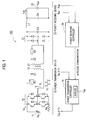
- Fig. 1 is a circuit diagram showing a configuration of a wireless power supply system according to a first embodiment of the present invention.
- the wireless power supply system 100 according to the present embodiment is configured to supply electric power via a wireless connection to a battery mounted on a vehicle so as to charge the battery therewith, and includes a power transmission device 10 provided on the ground side and a power receiving device 20 provided on the vehicle.
- the power transmission device 10 includes a DC power source 11 for outputting DC voltage obtained in such a manner as to control a power source (not shown in the drawing) by smoothing and an increase/decrease in voltage, an inverter circuit 12 for converting the DC voltage output from the DC power source 11 into AC voltage, and a power transmission coil 13 connected to the inverter circuit 12 on the output side.
- a resistor R1 and a capacitor C1 for noise removal are provided between the inverter circuit 12 and the power transmission coil 13.
- a shunt resistor Rs (current sensor) for measuring current supplied to the inverter circuit 12 is provided between the DC power source 11 and the inverter circuit 12.
- the power transmission device 10 further includes a power transmission controller 14 for controlling the operation of the power transmission device 10.
- the DC power source 11 includes, for example, a DC/DC converter capable of varying output voltage in accordance with a control signal output from the power transmission controller 14.
- the inverter circuit 12 includes four semiconductor switches such as IGBTs. The inverter circuit 12 converts the DC voltage output from the DC power source 11 into the AC voltage in such a manner as to turn on/off the respective semiconductor switches at a constant frequency in a constant duty ratio according to a drive signal output from the power transmission controller 14.
- the power receiving device 20 includes a power receiving coil 21, and a capacitor C2 and a resistor R2 for noise removal connected to the power receiving coil 21.
- the power receiving device 20 further includes a bridge rectifying circuit 22 for converting the AC voltage received by the power receiving coil 21 into DC voltage, a capacitor C3 for smoothing the DC voltage obtained by rectification, and a coil L1 and a capacitor C4 for suppressing current.
- the power receiving device 20 further includes a battery 23 charged with electric power and a power receiving controller 24 for controlling the operation of the power receiving device 20.
- the power transmission controller 14 regulates the transmission of the electric power based on the power supply command value P*.
- the power transmission controller 14 controls output voltage Vdc of the DC power source 11 and adjusts AC voltage V1 (inverter output voltage) output from the inverter circuit 12 so as to regulate the electric power transmitted by the power transmission coil 13.
- the output voltage Vdc of the DC power source 11 is in proportion to the AC voltage V1, the voltage Vdc may be used as the inverter output voltage.
- the power transmission controller 14 since the power transmission controller 14 and the power receiving controller 24 communicate with each other in first cycle T1, the power transmission controller 14 receives a new power supply command value P* in each cycle T1 so as to control the output voltage based on the received power supply command value P*.
- the power transmission controller 14 includes a memory 14a (storage section) for storing the power supply command value P* transmitted from the power receiving controller 24.
- the power transmission controller 14 also detects current Idc flowing into the input side of the inverter circuit 12, namely, power transmission coil current, so as to control the voltage Vdc or V1 based on the detected current Idc. As described below, the voltage Vdc or V1 is controlled based on the current Idc in second cycle T2 (here, T2 ⁇ T1).
- the power transmission controller 14 may detect the current I1 flowing through the circuit of the power transmission coil 13 as the power transmission coil current, instead of the current Idc, so as to control the voltage Vdc or V1 based on the detected current I1.
- the power receiving controller 24 obtains charge voltage Vbat of the battery 23 and current Ibat flowing into the battery 23, generates a power supply command value P* based on the charge voltage Vbat and the current Ibat, and transmits the power supply command value P* to the power transmission controller 14 via wireless communication.
- the power receiving controller 24 may also be configured to transmit the charge voltage Vbat and the current Ibat to the power transmission controller 14 so that the power supply command value P* is requested by the power transmission controller 14 based on the transmitted charge voltage Vbat and current Ibat.
- the power transmission device 10 In the state where the power transmission device 10 is provided on the ground side and the power receiving device 20 is provided on the vehicle, a driver of the vehicle moves the vehicle so that the power receiving coil 21 is opposed to the power transmission coil 13. Once the electric power is supplied to the power transmission coil 13 in the state where the power receiving coil 21 faces the power transmission coil 13, the electric power is transmitted to and received by the power receiving coil 21 so that the battery 23 is charged therewith. Thus, the electric power can be transmitted from the power transmission device 10 to the power receiving device 20 to charge the battery 23 with the electric power via a wireless connection.
- the power transmission controller 14 and the power receiving controller 24 may be configured, for example, as an integrated computer including a central processing unit (CPU) and storage means such as a RAM, a ROM and a hard disk.
- CPU central processing unit
- storage means such as a RAM, a ROM and a hard disk.
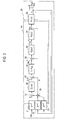
- the power transmission controller 14 includes a PI control block 36 having a transfer function C1(s), a control block 38 having a transfer function 1/Vdc, a PI control block 40 having a transfer function C2(s), a control model 41 of the inverter circuit 12 having a transfer function P2(s), and a control model 42 of a wireless power transmission unit including the power transmission coil 13 and the power receiving coil 21 and having a transfer function P1(s).
- the power receiving controller 24 includes first order lag elements 32, 33 provided on feedback paths of the voltage Vbat and the current Ibat output from the control model 42 to the power transmission controller 14.
- the power receiving controller 24 further includes a first order lag element 31 provided on a feedback path of the power supply command value P*.
- the power supply command value P* output from the power receiving controller 24 is supplied to a subtractor 34 provided in the power transmission controller 14 via the first order lag element 31.
- Data of the voltage Vbat of the battery 23 ( Fig. 1 ) is supplied to a multiplier 35 via the first order lag 33.
- Data of the current Ibat flowing through the battery 23 is supplied to the multiplier 35 via the first order lag element 32.
- the multiplier 35 multiplies the voltage Vbat and the current Ibat together to obtain an electric power measurement value P.
- the electric power measurement value P is supplied to the subtractor 34 and an adder 37.
- the subtractor 34 subtracts the electric power measurement value P from the power supply command value P* to obtain a deviation.
- the deviation thus obtained is multiplied by the transfer function C1(s) in the PI control block 36 to obtain a deviation ⁇ P.
- the adder 37 adds the electric power measurement value P to the deviation ⁇ P, and the value obtained by the addition is multiplied by 1/Vdc in the control block 38. As a result, a current command value Idc* is obtained.
- the electric power measurement value P may be obtained by the power receiving controller 24, and the obtained electric power measurement value P may be transmitted to the power transmission controller 14 via wireless communication.
- the current command value Idc* is supplied to a subtractor 39, and the subtractor 39 subtracts a current Idc output from the control model 41 from the current command value Idc*.
- the value obtained by the subtraction is multiplied by the transfer function C2(s) in the PI control block 40 to obtain a voltage command value Vdc*.
- the current command value Vdc* is multiplied by the transfer function P2(s) in the control model 41 to obtain the current Idc so as to be output to the control model 42.
- the current Idc is also fed back to the subtractor 39.
- the control model 42 multiplies the input current Idc by the transfer function P1(s) and outputs the value thus obtained.
- the wireless power supply system 100 includes two loops: a first loop in which Vbat and Ibat are fed back from the power receiving controller 24 to the power transmission controller to correct the power supply command value P* in each first cycle T1; and a second loop in which the current Idc output from the control model 41 is fed back so as to correct the voltage Vdc.
- the sampling cycle T2 in the second loop is shorter than the sampling cycle T1 in the first loop.
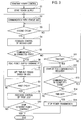
- the process starts power transmission from the power transmission device 10 to the power receiving device 20 in step S1.
- step S2 the power transmission device 10 starts communicating with the power receiving device 20 provided in the vehicle.
- step S3 the power transmission controller 14 provided in the power transmission device 10 determines whether the second cycle T2 has passed, and executes the feedback control of the second loop in step S4 when the second cycle T2 has passed. As shown in Fig. 2 , this feedback control performed is based on the deviation between the current Idc output from the control model 41 and the current command value Idc*. Therefore, the feedback control is executed only in the power transmission device 10 so as to adjust the voltage V1 to an appropriate value supplied to the power transmission coil 13.
- step S5 it is determined whether the power transmission controller 14 and the power receiving controller 24 are communicating with each other, and the process proceeds to step S6 when the communication is confirmed.
- step S6 it is determined whether the power transmission controller 14 and the power receiving controller 24 are communicating with each other, namely, when the communication therebetween is cut off, the process proceeds to step S 11.
- step S6 the power transmission controller 14 reads the power supply command value P* transmitted from the power receiving controller 24.
- the memory 14a stores the read power supply command value P*.
- each data of the charge voltage Vbat of the battery 23 and the current Ibat flowing through the battery 23 is transmitted to the power transmission controller 14.
- a time-out period (denoted by t1) depending on a SOC of the battery 23 is determined based on the power supply command value P* stored in the memory 14a.
- the SOC can be obtained based on the charge voltage Vbat and the current Ibat of the battery 23.
- the time-out period t1 represents a time for which the power supply from the power transmission device 10 to the power receiving device 20 can be continued after the communication between the power transmission controller 14 and the power receiving controller 24 is cut off.
- the time-out period t1 is determined depending on the SOC of the battery 23, for example, in such a manner as to shorten as the level of the SOC is higher, as shown in Fig. 6 .
- the time-out period t1 is a lapse of time after the communication between the power transmission controller 14 and the power receiving controller 24 is cut off. If the power transmission is continued in a state where the level of the SOC is high after the communication is cut off, the battery 23 may be overcharged because the electric power is supplied to the battery 23 excessively. Thus, the time-out period t1 is shortened when the level of the SOC is high so as to prevent such a problem.
- the power receiving controller 24 transmits measurement data of charge voltage of the battery 23 to the power transmission device 10 in the first cycle T1, and the power transmission controller 14 shortens the time-out period t1 as the charge voltage of the battery is higher based on the transmitted measurement data.
- the relationship between the SOC and the time-out period t1 is not limited to that as shown in the graph of Fig. 6 and may be configured such that the time-out period t1 is shortened continuously or gradually in association with an increase of the SOC.
- step S8 in Fig. 3 the power transmission controller 14 determines whether the first cycle T1 has passed.
- the power transmission controller 14 executes the feedback control of the first loop in step S9.
- the voltage V1 supplied to the power transmission coil 13 is obtained based on the current Idc obtained by use of the shunt resistor Rs and the power supply command value P* in such a manner as to divide the power supply command value P* by the current Idc.
- the control amount of the output voltage of the DC power source 11 is set to the voltage V1 thus obtained.
- a preferred electric power is transmitted from the power transmission coil 13 to the power receiving coil 21. Accordingly, the battery 23 provided in the power receiving device 20 can be charged with the preferred electric power.
- step S10 it is determined whether an operation of completing the constant power control is input, and the present process ends when the stop operation is input.
- the feedback control of the first loop is executed in the first cycle T1
- the feedback control of the second loop is executed in the second cycle T2 shorter than the first cycle T1 so as to control the electric power transmitted from the power transmission coil 13.
- step S5 when the communication is not confirmed (NO in step S5), the power transmission controller 14 determines in step S11 whether the time-out period t1 set in the processing in step S7 has elapsed. Namely, it is determined whether the time elapsed after the communication between the power transmission controller 14 and the power receiving controller 24 is cut off reaches the time-out period t1.
- step S11 When the time-out period t1 has not elapsed yet (NO in step S11), the process returns to step S2. Since the memory 14a stores the power supply command value P* used in the previous feedback control of the first loop, the feedback control of the second loop in step S3 is executed based on the previously-used power supply command value P*.
- the output power of the inverter circuit 12 is controlled by use of the power supply command value P* obtained via the previous communication and stored in the memory 14a.
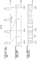
- the following is a specific explanation thereof with reference to Fig. 4 .
- the power receiving controller 24 transmits the power supply command value P* in the first cycle T1 (refer to Fig. 4(a) ).
- the power transmission controller 14 receives the power supply command value P* and controls the voltage supplied to the power transmission coil 13. Further, the feedback control for the current I1 in the second loop is continued from the point where the previous power supply command value P* is received to the point where the current power supply command value P* is received, so as to control the voltage supplied to the power transmission coil 13 (refer to Fig. 4(c) ).
- the feedback control is executed in such a manner as to continuously use the previously-received power supply command value P2.
- the power transmission controller 14 is in a stand-by mode for a communication recovery.
- step S13 the power transmission controller 14 determines whether the communication with the power receiving controller 24 recovers. When it is determined that the communication recovers, it is then determined again in step S14 whether the time-out period t1 has elapsed, and the process returns to step S12 when the time-out period t1 has not elapsed yet. When the time-out period t1 has elapsed, the power transmission controller 14 then stops transmitting the electric power in step S 15. That is, when the power transmission controller 14 cannot receive the power supply command value P*, the power transmission controller 14 calculates the lapse of time for which the power supply command value P* has not been received. When the lapse of time calculated reaches the predetermined time-out period t1, the transmission of the electric power is stopped.
- the wireless power supply system 100 performs the wireless communication between the power transmission controller 14 and the power receiving controller 24 as described above.
- the power receiving controller 24 transmits the power supply command value P* to the power transmission controller 14 in the first cycle T1.
- the power transmission controller 14 obtains the power supply command value P* and the current Idc detected in the shunt resistor Rs in the second cycle T2, obtains the voltage V1 supplied to the power transmission coil 13 based on the power supply command value P* and the current Idc, and controls the output voltage Vdc of the DC power source 11 to be set to the voltage V1 thus obtained or controls the drive of the inverter circuit 12.
- the communication between the power receiving controller 24 and the power transmission controller 14 can be retried plural times when, for example, the communication therebetween is not in a stable state, so as to increase the stability of the communication from the power receiving controller 24 to the power transmission controller 14.
- the transmission of the power supply command value P* in the relatively long first cycle T1 may not allow the system to immediately deal with a variation in relative impedance between the power transmission coil 13 and the power receiving coil 21 caused for a shorter period of time than the first cycle T1 to keep a constant level of the electric power transmitted.
- the system according to the present embodiment is configured such that the current I1 or Idc flowing through the power transmission coil 13 is detected in the second cycle T2 shorter than the first cycle T1 so as to control the output voltage of the inverter circuit 12 based on the power supply command value P* and the current I1 or Idc. Therefore, the system can keep the transmitted electric power at a constant level while immediately dealing with the variation of the relative impedance between the power transmission coil 13 and the power receiving coil 21 even when the positional relationship between the power transmission device 10 and the power receiving device 20 is suddenly changed and the relative impedance varies for a shorter period of time than the first cycle T1 in association with the rapid change of the positional relationship. Accordingly, the battery 23 provided in the power receiving device 20 can be charged with an appropriate electric power transmitted corresponding to the voltage and current of the battery 23.
- the power transmission controller 14 executes the feedback control for the current Idc based on the previously-transmitted power supply command value stored in the memory 14a (storage section).
- the system can promptly cope with a problem with the battery 23 of which charge is stopped so as to prevent trouble that the battery 23 has not been charged without the driver of the vehicle realizing it.
- the transmission of the electric power is stopped when the predetermined time-out period t1 has elapsed after the communication between the power transmission controller 14 and the power receiving controller 24 is cut off, so as to prevent the power transmission from being continued for a long period of time without the state of charge of the battery 23 confirmed. Accordingly, the battery 23 can be prevented from being overcharged.
- the time-out period t1 is shortened as the level of the SOC (charge voltage) of the battery 23 is higher, the battery 23 can be prevented from being overcharged more reliably.
- the feedback control of the first loop is again carried out so as to continuously charge the battery 23 with the electric power.
- a second embodiment of the present invention is explained below.
- the configurations of the devices in the present embodiment are the same as those in the first embodiment, and explanations thereof are not repeated below.
- the second embodiment differs from the first embodiment in the processing after step S11 shown in Fig. 3 .
- an operation of the wireless power supply system according to the second embodiment is explained with reference to the flowchart shown in Fig. 5 . Note that the same steps in the flowchart shown in Fig. 5 as those in Fig. 3 are denoted by the same reference signs.
- step S5 in Fig. 5 when the power transmission controller 14 and the power receiving controller 24 are not communicating with each other (NO in step S5), the power transmission controller 14 determines in step S11 whether the time-out period t1 set in the processing in step S7 has elapsed. Namely, it is determined whether the time elapsed after the communication between the power transmission controller 14 and the power receiving controller 24 is cut off reaches the time-out period t1.
- step S11 When the time-out period t1 has not elapsed yet (NO in step S11), the process returns to step S2. Since the memory 14a stores the power supply command value P* used in the previous feedback control of the first loop, the feedback control of the second loop in step S3 is executed based on the previously-used power supply command value P*.
- the power transmission controller 14 gradually decreases the power supply command value P* in step S11a. Namely, when the power transmission controller 14 cannot receive the power supply command value P*, the power transmission controller 14 calculates the lapse of time for which the power supply command value P* has not been received, and the power transmission controller 14 gradually decreases the transmission amount of the electric power when the calculated time reaches the time-out period t1.
- a relationship between the power supply command value P* and the time by which the power supply command value P* is gradually decreased to reach zero may be determined as shown in Fig. 7 , for example. Namely, the time t2 is shortened as the power supply command value P* is larger.
- step S12 the power transmission controller 14 determines whether the communication with the power receiving controller 24 recovers. When it is determined that the communication recovers in step S 13, it is then determined again in step S14 whether the time-out period t1 has elapsed, and the process returns to step S11a when the time-out period t1 has not elapsed yet. When the time-out period t1 has elapsed, the power transmission controller 14 then stops transmitting the electric power in step S 15.
- the feedback control of the second loop is only executed for the predetermined time-out period t1 so as to continuously charge the battery 23.
- the time-out period t1 has elapsed, the power transmission is not immediately stopped but continued while the power supply command value P* is gradually decreased.
- the communication recovers during this period, the system returns to the normal control.
- the power transmission controller 14 restarts regular transmission of the electric power by use of the received power supply command value P*.
- the battery 23 can be prevented from unnecessary interruption of charge even when the time-out period t1 has elapsed. Further, since the power supply command value P* is gradually decreased, a rapid variation of the current flowing through the power transmission coil 13 or the power receiving coil 21 can be suppressed, so as to prevent surge noise caused by the rapid variation of the current.
- the battery 23 can be prevented from being overcharged more reliably.
- the present invention can be applicable to the case where power supply from a power transmission device to a power receiving device can be continued even when wireless communication between the power transmission device and the power receiving device is stopped.
Landscapes
- Engineering & Computer Science (AREA)
- Power Engineering (AREA)
- Computer Networks & Wireless Communication (AREA)
- Transportation (AREA)
- Mechanical Engineering (AREA)
- Life Sciences & Earth Sciences (AREA)
- Sustainable Development (AREA)
- Sustainable Energy (AREA)
- Charge And Discharge Circuits For Batteries Or The Like (AREA)
- Electric Propulsion And Braking For Vehicles (AREA)
- Current-Collector Devices For Electrically Propelled Vehicles (AREA)
Applications Claiming Priority (1)
| Application Number | Priority Date | Filing Date | Title |
|---|---|---|---|
| PCT/JP2013/076045 WO2015045058A1 (ja) | 2013-09-26 | 2013-09-26 | 非接触給電システム及び送電装置 |
Publications (3)
| Publication Number | Publication Date |
|---|---|
| EP3051663A1 true EP3051663A1 (de) | 2016-08-03 |
| EP3051663A4 EP3051663A4 (de) | 2016-10-05 |
| EP3051663B1 EP3051663B1 (de) | 2019-06-19 |
Family
ID=52742263
Family Applications (1)
| Application Number | Title | Priority Date | Filing Date |
|---|---|---|---|
| EP13894705.6A Active EP3051663B1 (de) | 2013-09-26 | 2013-09-26 | Drahtlose stromversorgung und stromübertragungsvorrichtung |
Country Status (9)
| Country | Link |
|---|---|
| US (1) | US9776522B2 (de) |
| EP (1) | EP3051663B1 (de) |
| JP (1) | JP6103070B2 (de) |
| KR (1) | KR20160045816A (de) |
| CN (1) | CN105594097B (de) |
| BR (1) | BR112016006569B1 (de) |
| MX (1) | MX346611B (de) |
| RU (1) | RU2635349C2 (de) |
| WO (1) | WO2015045058A1 (de) |
Cited By (3)
| Publication number | Priority date | Publication date | Assignee | Title |
|---|---|---|---|---|
| EP3477812A4 (de) * | 2016-07-15 | 2019-05-01 | Huawei Technologies Co., Ltd. | Drahtlose ladeschaltung, drahtloses ladesystem und schaltkreissteuerungsverfahren |
| EP3457517A4 (de) * | 2016-05-13 | 2019-12-04 | LG Innotek Co., Ltd. | Verfahren zum drahtlosen laden sowie vorrichtung und system dafür |
| EP3595131A4 (de) * | 2017-03-10 | 2021-01-06 | Mitsubishi Electric Engineering Company, Limited | Resonanzleistungsendevorrichtung und resonanzleistungtransfersystem |
Families Citing this family (18)
| Publication number | Priority date | Publication date | Assignee | Title |
|---|---|---|---|---|
| JP2015089221A (ja) * | 2013-10-30 | 2015-05-07 | パイオニア株式会社 | 給電装置及び方法、並びにコンピュータプログラム |
| JP6260262B2 (ja) | 2013-12-25 | 2018-01-17 | トヨタ自動車株式会社 | 非接触電力伝送システムおよびその制御方法 |
| US9680332B2 (en) * | 2015-04-30 | 2017-06-13 | Delphi Technologies, Inc. | Wireless battery charger with wireless control system and method for control thereof |
| EP3748812A1 (de) | 2016-02-03 | 2020-12-09 | General Electric Company | Verfahren und system zum schutz eines systems zur drahtlosen stromübertragung |
| SG10201700633QA (en) * | 2016-02-03 | 2017-09-28 | Gen Electric | System and method for protecting a wireless power transfer system |
| CN106340916A (zh) * | 2016-09-05 | 2017-01-18 | 北京新能源汽车股份有限公司 | 一种汽车的充电方法、充电装置、充电系统及汽车 |
| SG10201707385XA (en) * | 2016-09-30 | 2018-04-27 | Gen Electric | Over voltage protection for a wireless power transfer system |
| US10727684B2 (en) * | 2016-10-10 | 2020-07-28 | Wits Co., Ltd. | Wireless power transmitter |
| JP6747964B2 (ja) | 2016-12-22 | 2020-08-26 | 東芝テック株式会社 | 非接触給電装置及びプログラム |
| JP6618519B2 (ja) * | 2017-11-22 | 2019-12-11 | 株式会社Subaru | 車両 |
| JP2018078793A (ja) * | 2017-12-06 | 2018-05-17 | トヨタ自動車株式会社 | 車両、受電装置および送電装置 |
| US10931147B2 (en) | 2018-03-29 | 2021-02-23 | Nuvolta Technologies (Hefei) Co., Ltd. | Hybrid power converter |
| WO2019203990A1 (en) | 2018-04-19 | 2019-10-24 | General Electric Company | Receiver unit of a wireless power transfer system |
| TWI857718B (zh) * | 2018-09-07 | 2024-10-01 | 美商奇異電器公司 | 無線電力傳送系統之接收器單元、方法及整合式電子組件 |
| CN110682806B (zh) * | 2019-07-19 | 2021-06-22 | 北京航空航天大学 | 一种基于无线充电技术的无轨电车及其运行控制方法 |
| US12588901B2 (en) | 2020-06-11 | 2026-03-31 | Kohler Co. | Health care mirror |
| US12042043B2 (en) | 2020-06-11 | 2024-07-23 | Kohler Co. | Temperature tracking mirror |
| JP2025172632A (ja) * | 2024-05-13 | 2025-11-26 | 本田技研工業株式会社 | 非接触電力伝送システム |
Family Cites Families (14)
| Publication number | Priority date | Publication date | Assignee | Title |
|---|---|---|---|---|
| JPH05116904A (ja) | 1991-10-23 | 1993-05-14 | Osaka Gas Co Ltd | 層間化合物の製造方法 |
| JPH06343202A (ja) * | 1993-06-01 | 1994-12-13 | Nissan Motor Co Ltd | 電気自動車の充電装置 |
| JP3778262B2 (ja) * | 2000-12-21 | 2006-05-24 | 株式会社マキタ | 充電方式及び電池パック |
| JP2009022122A (ja) * | 2007-07-13 | 2009-01-29 | Toko Inc | 非接触電力伝送装置 |
| JP2009273219A (ja) * | 2008-05-07 | 2009-11-19 | Nec Saitama Ltd | 充電回路 |
| JP2010028934A (ja) * | 2008-07-16 | 2010-02-04 | Seiko Epson Corp | 受電制御装置、受電装置および無接点電力伝送システム |
| RU2461946C1 (ru) * | 2008-10-09 | 2012-09-20 | Тойота Дзидося Кабусика Кайся | Устройство бесконтактного получения энергии и транспортное средство, содержащее такое устройство |
| KR101039678B1 (ko) | 2009-11-17 | 2011-06-09 | 현대자동차주식회사 | 하이브리드 차량의 전력변환장치 냉각 제어 방법 |
| JP5083480B2 (ja) * | 2010-12-01 | 2012-11-28 | トヨタ自動車株式会社 | 非接触給電設備、車両および非接触給電システムの制御方法 |
| JP5854640B2 (ja) * | 2011-05-25 | 2016-02-09 | キヤノン株式会社 | 電子機器、受電方法及びプログラム |
| US20140203774A1 (en) | 2011-09-29 | 2014-07-24 | Hitachi Power Solutions Co., Ltd. | Charging Control Device and Charging Control Method |
| KR101951358B1 (ko) * | 2011-12-15 | 2019-02-22 | 삼성전자주식회사 | 무선 전력 송신기 및 그 제어 방법 |
| JP5880049B2 (ja) | 2012-01-04 | 2016-03-08 | 株式会社豊田自動織機 | 充電システム |
| CN104137387B (zh) | 2012-02-29 | 2016-12-07 | 中国电力株式会社 | 非接触供电系统、供电装置、受电装置及非接触供电系统的控制方法 |
-
2013
- 2013-09-26 US US15/023,777 patent/US9776522B2/en active Active
- 2013-09-26 KR KR1020167007327A patent/KR20160045816A/ko not_active Ceased
- 2013-09-26 EP EP13894705.6A patent/EP3051663B1/de active Active
- 2013-09-26 RU RU2016113695A patent/RU2635349C2/ru active
- 2013-09-26 MX MX2016003765A patent/MX346611B/es active IP Right Grant
- 2013-09-26 BR BR112016006569-7A patent/BR112016006569B1/pt not_active IP Right Cessation
- 2013-09-26 JP JP2015538700A patent/JP6103070B2/ja active Active
- 2013-09-26 CN CN201380079836.9A patent/CN105594097B/zh active Active
- 2013-09-26 WO PCT/JP2013/076045 patent/WO2015045058A1/ja not_active Ceased
Cited By (3)
| Publication number | Priority date | Publication date | Assignee | Title |
|---|---|---|---|---|
| EP3457517A4 (de) * | 2016-05-13 | 2019-12-04 | LG Innotek Co., Ltd. | Verfahren zum drahtlosen laden sowie vorrichtung und system dafür |
| EP3477812A4 (de) * | 2016-07-15 | 2019-05-01 | Huawei Technologies Co., Ltd. | Drahtlose ladeschaltung, drahtloses ladesystem und schaltkreissteuerungsverfahren |
| EP3595131A4 (de) * | 2017-03-10 | 2021-01-06 | Mitsubishi Electric Engineering Company, Limited | Resonanzleistungsendevorrichtung und resonanzleistungtransfersystem |
Also Published As
| Publication number | Publication date |
|---|---|
| US9776522B2 (en) | 2017-10-03 |
| EP3051663A4 (de) | 2016-10-05 |
| WO2015045058A1 (ja) | 2015-04-02 |
| JP6103070B2 (ja) | 2017-03-29 |
| EP3051663B1 (de) | 2019-06-19 |
| RU2016113695A (ru) | 2017-10-31 |
| MX346611B (es) | 2017-03-27 |
| JPWO2015045058A1 (ja) | 2017-03-02 |
| CN105594097A (zh) | 2016-05-18 |
| KR20160045816A (ko) | 2016-04-27 |
| RU2635349C2 (ru) | 2017-11-13 |
| BR112016006569A2 (pt) | 2017-08-01 |
| BR112016006569B1 (pt) | 2022-02-08 |
| US20160214488A1 (en) | 2016-07-28 |
| CN105594097B (zh) | 2017-08-22 |
| MX2016003765A (es) | 2016-07-08 |
Similar Documents
| Publication | Publication Date | Title |
|---|---|---|
| EP3051663B1 (de) | Drahtlose stromversorgung und stromübertragungsvorrichtung | |
| US8310209B2 (en) | Battery charger and method for charging a battery | |
| JP5593849B2 (ja) | 組電池の監視装置 | |
| EP2415148B1 (de) | Lastteilungskonfiguration in einem stromumrichtersystem | |
| KR101976909B1 (ko) | 와이어리스 수전 장치, 그 제어 회로 및 제어 방법 | |
| EP3800795B1 (de) | Vorrichtung zur drahtlosen stromübertragung | |
| JP2019140775A (ja) | 車載充電装置、及び車載充電装置の制御方法 | |
| EP2783903B1 (de) | Signalerzeugungsschaltung zur Erzeugung eines Pilotsignals | |
| KR20180008619A (ko) | 어댑터 및 충전 제어 방법 | |
| US9397572B2 (en) | Control apparatus for DC-DC converter | |
| EP2860844A1 (de) | Adaptives Ladegerät zur Maximierung der Laderate | |
| US10418826B2 (en) | Battery device and charging device | |
| US20250385537A1 (en) | Wireless charging receiver integrated battery management system and method | |
| US20130208511A1 (en) | Switch mode power supply module and associated hiccup control method | |
| US20180212457A1 (en) | Method and device for operating an electrical system, and electrical system | |
| KR20230038572A (ko) | 무선 전력 수신 장치에서의 전력 제어기 | |
| WO2016143296A1 (ja) | 蓄電制御システム及び充放電制御方法 | |
| JP2019047675A (ja) | 電力供給システム | |
| CN104685752A (zh) | 具有谐振变换器的电路布置和用于运行谐振变换器的方法 | |
| JP2019047674A (ja) | 電力供給システム | |
| JP2019118193A (ja) | 二次電池の充電回路及び充電方法 | |
| HK1188340A (en) | Switch mode power supply module and associated hiccup control method |
Legal Events
| Date | Code | Title | Description |
|---|---|---|---|
| PUAI | Public reference made under article 153(3) epc to a published international application that has entered the european phase |
Free format text: ORIGINAL CODE: 0009012 |
|
| 17P | Request for examination filed |
Effective date: 20160321 |
|
| AK | Designated contracting states |
Kind code of ref document: A1 Designated state(s): AL AT BE BG CH CY CZ DE DK EE ES FI FR GB GR HR HU IE IS IT LI LT LU LV MC MK MT NL NO PL PT RO RS SE SI SK SM TR |
|
| AX | Request for extension of the european patent |
Extension state: BA ME |
|
| A4 | Supplementary search report drawn up and despatched |
Effective date: 20160906 |
|
| RIC1 | Information provided on ipc code assigned before grant |
Ipc: H02J 50/00 20160101AFI20160831BHEP Ipc: H02J 50/12 20160101ALI20160831BHEP Ipc: H02J 50/80 20160101ALI20160831BHEP |
|
| DAX | Request for extension of the european patent (deleted) | ||
| STAA | Information on the status of an ep patent application or granted ep patent |
Free format text: STATUS: EXAMINATION IS IN PROGRESS |
|
| 17Q | First examination report despatched |
Effective date: 20170613 |
|
| GRAP | Despatch of communication of intention to grant a patent |
Free format text: ORIGINAL CODE: EPIDOSNIGR1 |
|
| STAA | Information on the status of an ep patent application or granted ep patent |
Free format text: STATUS: GRANT OF PATENT IS INTENDED |
|
| RIN1 | Information on inventor provided before grant (corrected) |
Inventor name: OKAMOTO, TOMOFUMI |
|
| INTG | Intention to grant announced |
Effective date: 20190313 |
|
| GRAS | Grant fee paid |
Free format text: ORIGINAL CODE: EPIDOSNIGR3 |
|
| GRAA | (expected) grant |
Free format text: ORIGINAL CODE: 0009210 |
|
| STAA | Information on the status of an ep patent application or granted ep patent |
Free format text: STATUS: THE PATENT HAS BEEN GRANTED |
|
| AK | Designated contracting states |
Kind code of ref document: B1 Designated state(s): AL AT BE BG CH CY CZ DE DK EE ES FI FR GB GR HR HU IE IS IT LI LT LU LV MC MK MT NL NO PL PT RO RS SE SI SK SM TR |
|
| REG | Reference to a national code |
Ref country code: GB Ref legal event code: FG4D |
|
| REG | Reference to a national code |
Ref country code: CH Ref legal event code: EP |
|
| REG | Reference to a national code |
Ref country code: IE Ref legal event code: FG4D |
|
| REG | Reference to a national code |
Ref country code: AT Ref legal event code: REF Ref document number: 1146723 Country of ref document: AT Kind code of ref document: T Effective date: 20190715 |
|
| REG | Reference to a national code |
Ref country code: DE Ref legal event code: R096 Ref document number: 602013056977 Country of ref document: DE |
|
| REG | Reference to a national code |
Ref country code: NL Ref legal event code: MP Effective date: 20190619 |
|
| PG25 | Lapsed in a contracting state [announced via postgrant information from national office to epo] |
Ref country code: HR Free format text: LAPSE BECAUSE OF FAILURE TO SUBMIT A TRANSLATION OF THE DESCRIPTION OR TO PAY THE FEE WITHIN THE PRESCRIBED TIME-LIMIT Effective date: 20190619 Ref country code: LT Free format text: LAPSE BECAUSE OF FAILURE TO SUBMIT A TRANSLATION OF THE DESCRIPTION OR TO PAY THE FEE WITHIN THE PRESCRIBED TIME-LIMIT Effective date: 20190619 Ref country code: NO Free format text: LAPSE BECAUSE OF FAILURE TO SUBMIT A TRANSLATION OF THE DESCRIPTION OR TO PAY THE FEE WITHIN THE PRESCRIBED TIME-LIMIT Effective date: 20190919 Ref country code: FI Free format text: LAPSE BECAUSE OF FAILURE TO SUBMIT A TRANSLATION OF THE DESCRIPTION OR TO PAY THE FEE WITHIN THE PRESCRIBED TIME-LIMIT Effective date: 20190619 Ref country code: SE Free format text: LAPSE BECAUSE OF FAILURE TO SUBMIT A TRANSLATION OF THE DESCRIPTION OR TO PAY THE FEE WITHIN THE PRESCRIBED TIME-LIMIT Effective date: 20190619 Ref country code: AL Free format text: LAPSE BECAUSE OF FAILURE TO SUBMIT A TRANSLATION OF THE DESCRIPTION OR TO PAY THE FEE WITHIN THE PRESCRIBED TIME-LIMIT Effective date: 20190619 |
|
| REG | Reference to a national code |
Ref country code: LT Ref legal event code: MG4D |
|
| PG25 | Lapsed in a contracting state [announced via postgrant information from national office to epo] |
Ref country code: LV Free format text: LAPSE BECAUSE OF FAILURE TO SUBMIT A TRANSLATION OF THE DESCRIPTION OR TO PAY THE FEE WITHIN THE PRESCRIBED TIME-LIMIT Effective date: 20190619 Ref country code: RS Free format text: LAPSE BECAUSE OF FAILURE TO SUBMIT A TRANSLATION OF THE DESCRIPTION OR TO PAY THE FEE WITHIN THE PRESCRIBED TIME-LIMIT Effective date: 20190619 Ref country code: BG Free format text: LAPSE BECAUSE OF FAILURE TO SUBMIT A TRANSLATION OF THE DESCRIPTION OR TO PAY THE FEE WITHIN THE PRESCRIBED TIME-LIMIT Effective date: 20190919 Ref country code: GR Free format text: LAPSE BECAUSE OF FAILURE TO SUBMIT A TRANSLATION OF THE DESCRIPTION OR TO PAY THE FEE WITHIN THE PRESCRIBED TIME-LIMIT Effective date: 20190920 |
|
| REG | Reference to a national code |
Ref country code: AT Ref legal event code: MK05 Ref document number: 1146723 Country of ref document: AT Kind code of ref document: T Effective date: 20190619 |
|
| PG25 | Lapsed in a contracting state [announced via postgrant information from national office to epo] |
Ref country code: NL Free format text: LAPSE BECAUSE OF FAILURE TO SUBMIT A TRANSLATION OF THE DESCRIPTION OR TO PAY THE FEE WITHIN THE PRESCRIBED TIME-LIMIT Effective date: 20190619 Ref country code: AT Free format text: LAPSE BECAUSE OF FAILURE TO SUBMIT A TRANSLATION OF THE DESCRIPTION OR TO PAY THE FEE WITHIN THE PRESCRIBED TIME-LIMIT Effective date: 20190619 Ref country code: RO Free format text: LAPSE BECAUSE OF FAILURE TO SUBMIT A TRANSLATION OF THE DESCRIPTION OR TO PAY THE FEE WITHIN THE PRESCRIBED TIME-LIMIT Effective date: 20190619 Ref country code: CZ Free format text: LAPSE BECAUSE OF FAILURE TO SUBMIT A TRANSLATION OF THE DESCRIPTION OR TO PAY THE FEE WITHIN THE PRESCRIBED TIME-LIMIT Effective date: 20190619 Ref country code: SK Free format text: LAPSE BECAUSE OF FAILURE TO SUBMIT A TRANSLATION OF THE DESCRIPTION OR TO PAY THE FEE WITHIN THE PRESCRIBED TIME-LIMIT Effective date: 20190619 Ref country code: EE Free format text: LAPSE BECAUSE OF FAILURE TO SUBMIT A TRANSLATION OF THE DESCRIPTION OR TO PAY THE FEE WITHIN THE PRESCRIBED TIME-LIMIT Effective date: 20190619 Ref country code: PT Free format text: LAPSE BECAUSE OF FAILURE TO SUBMIT A TRANSLATION OF THE DESCRIPTION OR TO PAY THE FEE WITHIN THE PRESCRIBED TIME-LIMIT Effective date: 20191021 |
|
| PG25 | Lapsed in a contracting state [announced via postgrant information from national office to epo] |
Ref country code: IS Free format text: LAPSE BECAUSE OF FAILURE TO SUBMIT A TRANSLATION OF THE DESCRIPTION OR TO PAY THE FEE WITHIN THE PRESCRIBED TIME-LIMIT Effective date: 20191019 Ref country code: SM Free format text: LAPSE BECAUSE OF FAILURE TO SUBMIT A TRANSLATION OF THE DESCRIPTION OR TO PAY THE FEE WITHIN THE PRESCRIBED TIME-LIMIT Effective date: 20190619 Ref country code: ES Free format text: LAPSE BECAUSE OF FAILURE TO SUBMIT A TRANSLATION OF THE DESCRIPTION OR TO PAY THE FEE WITHIN THE PRESCRIBED TIME-LIMIT Effective date: 20190619 Ref country code: IT Free format text: LAPSE BECAUSE OF FAILURE TO SUBMIT A TRANSLATION OF THE DESCRIPTION OR TO PAY THE FEE WITHIN THE PRESCRIBED TIME-LIMIT Effective date: 20190619 |
|
| PG25 | Lapsed in a contracting state [announced via postgrant information from national office to epo] |
Ref country code: TR Free format text: LAPSE BECAUSE OF FAILURE TO SUBMIT A TRANSLATION OF THE DESCRIPTION OR TO PAY THE FEE WITHIN THE PRESCRIBED TIME-LIMIT Effective date: 20190619 |
|
| PG25 | Lapsed in a contracting state [announced via postgrant information from national office to epo] |
Ref country code: DK Free format text: LAPSE BECAUSE OF FAILURE TO SUBMIT A TRANSLATION OF THE DESCRIPTION OR TO PAY THE FEE WITHIN THE PRESCRIBED TIME-LIMIT Effective date: 20190619 Ref country code: PL Free format text: LAPSE BECAUSE OF FAILURE TO SUBMIT A TRANSLATION OF THE DESCRIPTION OR TO PAY THE FEE WITHIN THE PRESCRIBED TIME-LIMIT Effective date: 20190619 |
|
| PG25 | Lapsed in a contracting state [announced via postgrant information from national office to epo] |
Ref country code: IS Free format text: LAPSE BECAUSE OF FAILURE TO SUBMIT A TRANSLATION OF THE DESCRIPTION OR TO PAY THE FEE WITHIN THE PRESCRIBED TIME-LIMIT Effective date: 20200224 Ref country code: MC Free format text: LAPSE BECAUSE OF FAILURE TO SUBMIT A TRANSLATION OF THE DESCRIPTION OR TO PAY THE FEE WITHIN THE PRESCRIBED TIME-LIMIT Effective date: 20190619 |
|
| REG | Reference to a national code |
Ref country code: CH Ref legal event code: PL |
|
| REG | Reference to a national code |
Ref country code: DE Ref legal event code: R097 Ref document number: 602013056977 Country of ref document: DE |
|
| PLBE | No opposition filed within time limit |
Free format text: ORIGINAL CODE: 0009261 |
|
| STAA | Information on the status of an ep patent application or granted ep patent |
Free format text: STATUS: NO OPPOSITION FILED WITHIN TIME LIMIT |
|
| PG2D | Information on lapse in contracting state deleted |
Ref country code: IS |
|
| PG25 | Lapsed in a contracting state [announced via postgrant information from national office to epo] |
Ref country code: LU Free format text: LAPSE BECAUSE OF NON-PAYMENT OF DUE FEES Effective date: 20190926 Ref country code: IE Free format text: LAPSE BECAUSE OF NON-PAYMENT OF DUE FEES Effective date: 20190926 Ref country code: CH Free format text: LAPSE BECAUSE OF NON-PAYMENT OF DUE FEES Effective date: 20190930 Ref country code: LI Free format text: LAPSE BECAUSE OF NON-PAYMENT OF DUE FEES Effective date: 20190930 |
|
| REG | Reference to a national code |
Ref country code: BE Ref legal event code: MM Effective date: 20190930 |
|
| 26N | No opposition filed |
Effective date: 20200603 |
|
| PG25 | Lapsed in a contracting state [announced via postgrant information from national office to epo] |
Ref country code: SI Free format text: LAPSE BECAUSE OF FAILURE TO SUBMIT A TRANSLATION OF THE DESCRIPTION OR TO PAY THE FEE WITHIN THE PRESCRIBED TIME-LIMIT Effective date: 20190619 Ref country code: BE Free format text: LAPSE BECAUSE OF NON-PAYMENT OF DUE FEES Effective date: 20190930 |
|
| PG25 | Lapsed in a contracting state [announced via postgrant information from national office to epo] |
Ref country code: CY Free format text: LAPSE BECAUSE OF FAILURE TO SUBMIT A TRANSLATION OF THE DESCRIPTION OR TO PAY THE FEE WITHIN THE PRESCRIBED TIME-LIMIT Effective date: 20190619 |
|
| PG25 | Lapsed in a contracting state [announced via postgrant information from national office to epo] |
Ref country code: MT Free format text: LAPSE BECAUSE OF FAILURE TO SUBMIT A TRANSLATION OF THE DESCRIPTION OR TO PAY THE FEE WITHIN THE PRESCRIBED TIME-LIMIT Effective date: 20190619 Ref country code: HU Free format text: LAPSE BECAUSE OF FAILURE TO SUBMIT A TRANSLATION OF THE DESCRIPTION OR TO PAY THE FEE WITHIN THE PRESCRIBED TIME-LIMIT; INVALID AB INITIO Effective date: 20130926 |
|
| PG25 | Lapsed in a contracting state [announced via postgrant information from national office to epo] |
Ref country code: MK Free format text: LAPSE BECAUSE OF FAILURE TO SUBMIT A TRANSLATION OF THE DESCRIPTION OR TO PAY THE FEE WITHIN THE PRESCRIBED TIME-LIMIT Effective date: 20190619 |
|
| PGFP | Annual fee paid to national office [announced via postgrant information from national office to epo] |
Ref country code: DE Payment date: 20250820 Year of fee payment: 13 |
|
| PGFP | Annual fee paid to national office [announced via postgrant information from national office to epo] |
Ref country code: GB Payment date: 20250820 Year of fee payment: 13 |
|
| PGFP | Annual fee paid to national office [announced via postgrant information from national office to epo] |
Ref country code: FR Payment date: 20250820 Year of fee payment: 13 |