EP3051649A1 - Dispositif de protection - Google Patents
Dispositif de protection Download PDFInfo
- Publication number
- EP3051649A1 EP3051649A1 EP14847019.8A EP14847019A EP3051649A1 EP 3051649 A1 EP3051649 A1 EP 3051649A1 EP 14847019 A EP14847019 A EP 14847019A EP 3051649 A1 EP3051649 A1 EP 3051649A1
- Authority
- EP
- European Patent Office
- Prior art keywords
- component
- protection device
- ptc
- terminal
- resistive
- Prior art date
- Legal status (The legal status is an assumption and is not a legal conclusion. Google has not performed a legal analysis and makes no representation as to the accuracy of the status listed.)
- Withdrawn
Links
Images
Classifications
-
- H—ELECTRICITY
- H02—GENERATION; CONVERSION OR DISTRIBUTION OF ELECTRIC POWER
- H02H—EMERGENCY PROTECTIVE CIRCUIT ARRANGEMENTS
- H02H3/00—Emergency protective circuit arrangements for automatic disconnection directly responsive to an undesired change from normal electric working condition with or without subsequent reconnection ; integrated protection
- H02H3/08—Emergency protective circuit arrangements for automatic disconnection directly responsive to an undesired change from normal electric working condition with or without subsequent reconnection ; integrated protection responsive to excess current
- H02H3/085—Emergency protective circuit arrangements for automatic disconnection directly responsive to an undesired change from normal electric working condition with or without subsequent reconnection ; integrated protection responsive to excess current making use of a thermal sensor, e.g. thermistor, heated by the excess current
-
- H—ELECTRICITY
- H01—ELECTRIC ELEMENTS
- H01C—RESISTORS
- H01C3/00—Non-adjustable metal resistors made of wire or ribbon, e.g. coiled, woven or formed as grids
- H01C3/14—Non-adjustable metal resistors made of wire or ribbon, e.g. coiled, woven or formed as grids the resistive element being formed in two or more coils or loops continuously wound as a spiral, helical or toroidal winding
-
- H—ELECTRICITY
- H02—GENERATION; CONVERSION OR DISTRIBUTION OF ELECTRIC POWER
- H02H—EMERGENCY PROTECTIVE CIRCUIT ARRANGEMENTS
- H02H9/00—Emergency protective circuit arrangements for limiting excess current or voltage without disconnection
- H02H9/001—Emergency protective circuit arrangements for limiting excess current or voltage without disconnection limiting speed of change of electric quantities, e.g. soft switching on or off
-
- H—ELECTRICITY
- H02—GENERATION; CONVERSION OR DISTRIBUTION OF ELECTRIC POWER
- H02H—EMERGENCY PROTECTIVE CIRCUIT ARRANGEMENTS
- H02H9/00—Emergency protective circuit arrangements for limiting excess current or voltage without disconnection
- H02H9/02—Emergency protective circuit arrangements for limiting excess current or voltage without disconnection responsive to excess current
- H02H9/026—Current limitation using PTC resistors, i.e. resistors with a large positive temperature coefficient
Definitions
- the present invention relates to a protection device comprising a PTC component and a resistive component.
- various protection devices or various protection circuits are used to protect electric elements or a circuit from a transitional excessive current that may flow immediately after a power is turned on (hereinafter, also referred to as "inrush current") and from various abnormally large currents such as a continuous excessive current generated by any abnormality, for example, short-circuiting (hereinafter, also referred to simply as “excessive current”), that is, an abnormal current.
- Patent Document 1 discloses a resistive device comprising a thermal fuse.
- a resistive component and the thermal fuse component are electrically connected to each other in series, and the resistive device is configured such that, when an inrush current or an excessive current flows through the resistive component comprising the thermal fuse, a Joule heat is generated in the resistive component, the thermal fuse component is fused by this heat, and the inrush current or the excessive current is interrupted, and thereby the electronic or the electric apparatus are protected.
- Patent Document 1 Japanese Patent Publication No. 2004-241665
- an activating temperature of the thermal fuse component that is, a melting point of a material constituting the thermal fuse element is increased.
- the time period necessary for the fusing of the thermal fuse becomes long and the apparatus may be damaged by the excessive current when the smoothing capacitor is shortcircuited. Since the activating temperature of the thermal fuse component is determined by the melting point of the material constituting the thermal fuse component and a temperature capable of being set as the activating temperature is limited and any precise temperature adjustment is difficult.
- a problem to be solved by the present invention is to provide a protection device that can more surely protect an electronic or an electric apparatus even when an inrush current value is large and its magnitude has large dispersion, and that has a recovery property.
- a protection device comprising: a PTC component; a resistive component; and a first terminal and a second terminal, wherein the first terminal, the PTC component, the resistive component, and the second terminal are electrically connected in series in this order.
- a protection circuit comprising the protection device.
- an electric apparatus comprising the protection device or the protection circuit.
- a protection device which can more surely interrupt the inrush current and the excessive current, and has a recovery property can be provided.
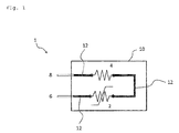
- Fig. 1 schematically shows a wiring diagram of one embodiment of a protection device of the present invention (the PTC component and the resistive component are depicted by graphic symbols for simplicity).
- a protection device of the present invention comprises a first terminal, a PTC component, a resistive component, and a second terminal that are electrically connected to each other in series in this order.
- the resistive component suppresses the flow of the current and the PTC component trips (that is, activates) to become a high resistance state, and then substantially interrupts the current (while a very small current may flow as a leaking current).
- the inrush current is generated mainly attributable to capacitance (including floating capacitance) in an electronic apparatus or an electronic circuit, and is therefore attenuated with accumulation of a charge in the capacitance.
- the protection device of the present invention provides the protection against the inrush current and the abnormal current, and simultaneously has a recovery property.
- the protection device of the present invention uses the PTC component, the protection device can provide a proper protection even against an abnormal heat generation.
- abnormal heat generation means a phenomenon that an unexpected heat generation occurs in a circuit or an apparatus, or in the vicinity thereof, and an ambient temperature of the protection device reaches an abnormally high temperature.
- ambient temperature means a temperature of the ambient air surrounding a component such as the protection device in this case, or a temperature of another member in contact with the protection device.
- abnormally high temperature does not mean a specific temperature, is appropriately determined depending on an use, a circuit or an apparatus to be protected, or the like, and means, for example, a temperature that is higher by a predetermined value than a temperature range permitted for an ordinary operation of the apparatus, a temperature exceeding the rated temperature of a used part by a predetermined value, and the like.
- the PTC component used in the protection device of the present invention is not particularly limited, and either a ceramic PTC component or a polymer PTC component may be used.
- the polymer PTC component is preferably used since a self-destruction is unlikely to occur even when its temperature reaches over a certain temperature in comparison with the ceramic PTC component, and the ceramic PTC component has an inductance component and has large floating capacitance as a result of which the inrush current is large.
- the above mentioned polymer PTC component comprises a laminate PTC element which is formed by extruding an electrically conductive composition containing a polymer (for example, a polyethylene, a polyvinylidene fluoride, or the like) in which an electrically conductive filler (for example, carbon black, nickel alloy, or the like) is dispersed, and electrodes (for example, metal foils) which are disposed on both sides thereof.
- a polymer for example, a polyethylene, a polyvinylidene fluoride, or the like
- an electrically conductive filler for example, carbon black, nickel alloy, or the like
- electrodes for example, metal foils
- the holding current of the PTC component is not particularly limited and can appropriately be selected depending on the magnitude of the expected inrush current.
- the PTC component activates for the stationary current in the case where the holding current is too small, and does not activate when an inrush current flows therethrough in the case where the holding current is too large. Therefore, the holding current is in a range, for example, 0.1 to 5 A, preferably 0.1 to 2 A, and more preferably 0.1 to 0.55 A.
- the "holding current” used herein means the largest current which is able to flow through the PTC component at the room temperature (specifically, 25°C) without causing the PTC component to activate.
- the "stationary current” means a current in the case where the value of the current flowing through an electronic apparatus or an electronic circuit is substantially constant, that is, a current flowing through the electronic apparatus or the electronic circuit when the electronic apparatus or the electronic circuit operates without any abnormality.
- the withstanding voltage of the PTC component is not particularly limited, for example, only has to be equal to or higher than an AC voltage of the ordinary household power source.
- the withstanding voltage is, specifically, 100 Vac or higher, preferably 140 Vac or higher, more preferably 240 Vac or higher, and further preferably 300 Vac or higher.
- the withstanding voltage of the PTC component is set to be, for example, 500 Vac or higher and to especially be 530 Vac or higher depending on a used transformer.
- the "withstanding voltage” used herein means the maximal value of the voltage at which the PTC component can normally activate. Specifically, the withstanding voltage is determined as follows.
- the withstanding voltage means a voltage such that, when the voltage is applied to the PTC component, the resistance value of the PTC component depending on the applied voltage is 70% of a 1000-fold value of the standard resistance value (that is, the resistance value at 25°C) of the PTC component.
- the resistance value at the room temperature (specifically, 25°C) of the PTC component is not particularly limited, and can properly be selected depending on the purpose.
- the resistance value of the polymer PTC component can be set to be 0.05 Q or more such that the polymer PTC component maintains a state of tripping at a voltage of 265 V.
- the resistance value of the polymer PTC component can be set to be 0.45 ⁇ or more.
- the resistance value of the polymer PTC component at the room temperature is 0.05 to 65 ⁇ , more preferably 0.30 to 10 ⁇ , and further preferably 0.45 to 2.4 ⁇ .
- the resistance value of the polymer PTC component used herein means a resistance value (measured by four-terminal method, applied current of a measurement range of a resistance measurement equipment: 100 mA) which is calculated from an applied voltage and a current value which is measured when the applied voltage of 6.5 mV (direct current) is applied at 25°C between both electrodes of a PTC component which is produced by the pressure-bonding of electrodes (preferably, nickel foils) on both sides of a PTC element obtained by the extrusion of an electrically conductive composition comprising a polymer. It is noted that since a resistance value of the electrodes is negligibly small in comparison with the resistance value of the PTC element, the resistance value of the PTC component is substantially equal to the resistance value of the PTC element.
- the resistive component used in the protection device of the present invention is not particularly limited and a general resistive component can be used.
- the resistive component include, for example, a wire wound resistor, a cement resistor, a chip resistor, a carbon coated resistor, a metal film resistor, a metal oxide film resistor, and the like.
- the wire wound resistor or the cement resistor is preferably used since these resistors can more effectively suppress the inrush current and the excessive current.
- the resistive component suppresses the flows of the inrush current and the excessive current flowing through the circuit to be protected. Additionally, the resistive component also has a function of, when the PTC component trips and recovers thereafter and the resistance value of the PTC component is varied from that before the tripping, alleviating the influence given by the variation of the resistance value on the current flowing through the circuit to be protected. For example, in the case where it is assumed that the resistive component is not present, when the resistance value of the PTC component becomes a double resistance value after its recovery compared to the resistance value before the tripping, the current flowing through the circuit is reduced to 50% of the current before the tripping.
- the value of the current flowing through the circuit can be maintained to be about 80% of that before the tripping.
- the resistance value of the resistive component may be, for example, at least a 10-fold value, for example a 10- to a 50-fold value, preferably a 30- to a 50-fold value of the resistance value of the PTC component at the room temperature (specifically, 25°C).
- a 10-fold value or more of the resistance value of the resistive component the influence given by the variation of the resistance value of the PTC component on the current flowing through the circuit can be suppressed.
- the resistance value of the resistive component to be a 50-fold value or less of the resistance value of the PTC component, the power consumption by the resistive component can become smaller.
- the resistance value of the resistive component is not particularly limited, but may be, specifically 1 to 650 ⁇ , preferably 1.5 to 500 ⁇ , and more preferably 2 to 50 ⁇ .
- the PTC component may be under the influence of the Joule heat generated by the resistive component (hereinafter, also referred to as "under the heat influence").
- the state where the PTC component is under the heat influence of the resistive component means an environment where the PTC component can trip due to the Joule heat generated by the resistive component when an inrush current or an excessive current occurs.
- the protection device of the present invention comprises the first terminal and the second terminal electrically connected to the PTC component and the resistive component, respectively. These terminals provide a function of connecting the protection device of the present invention to another electronic element.
- each of elements may directly be connected to each other or may be connected to each other via a lead.
- the connection can be established by using a known means such as soldering, welding, or the like.
- the protection device of the present invention may comprise an outer cover (that is, a housing or a casing).
- the outer cover has a function of protecting the PTC component and the resistive component, and facilitates the handling of the protection device.
- the PTC component, the resistive component, and a portion of each of the first terminal and the second terminal are covered by the outer cover, and the remaining portion of each of the first terminal and the second terminal protrudes from the outer cover.
- the outer cover is not particularly limited and may be an ordinarily used one such as a resin casing or the like.
- a wiring diagram of one embodiment of the protection device 1 of the present invention is schematically shown (in which the PTC component and the resistive component are depicted using graphic symbols for simplicity).
- each of elements (the PTC component 2, the resistive component 4, the first terminal 6, and the second terminal 8) is connected to each other via the lead 12.
- the PTC component 2 and the resistive component 4 are electrically connected to each other in series via the lead 12 and are disposed adjacent to each other such that the PTC component is under the heat influence of the resistive component.
- the first terminal 6 and the second terminal 8 are electrically connected to the PTC component 2 and the resistive component 4 in series via the lead 12, respectively.
- the protection device of the present invention is connected to other electric elements by the portion of the first terminal 6 and the portion of the second terminal 8.
- the protection device of the present invention is not limited to the illustrated embodiment.
- the first terminal and the second terminal protrude from the same face of the casing, however the first terminal and the second terminal may protrude from different surfaces of the casing, for example, surfaces that face each other.
- a resin having a high heat conductivity such as a silicone resin
- sensitivity of the PTC component to the heat influence of the resistive component may be increased.
- various modifications of the protection device of the present invention can be performed within a scope in which its functions are not lost.
- the protection device of the present invention can be used as an inrush current limiting component for various electronic and various electric apparatuses.
Landscapes
- Engineering & Computer Science (AREA)
- Power Engineering (AREA)
- Microelectronics & Electronic Packaging (AREA)
- Emergency Protection Circuit Devices (AREA)
- Thermistors And Varistors (AREA)
Applications Claiming Priority (2)
| Application Number | Priority Date | Filing Date | Title |
|---|---|---|---|
| JP2013198819 | 2013-09-25 | ||
| PCT/JP2014/075306 WO2015046258A1 (fr) | 2013-09-25 | 2014-09-24 | Dispositif de protection |
Publications (2)
| Publication Number | Publication Date |
|---|---|
| EP3051649A1 true EP3051649A1 (fr) | 2016-08-03 |
| EP3051649A4 EP3051649A4 (fr) | 2017-06-21 |
Family
ID=52743393
Family Applications (1)
| Application Number | Title | Priority Date | Filing Date |
|---|---|---|---|
| EP14847019.8A Withdrawn EP3051649A4 (fr) | 2013-09-25 | 2014-09-24 | Dispositif de protection |
Country Status (7)
| Country | Link |
|---|---|
| US (1) | US10396543B2 (fr) |
| EP (1) | EP3051649A4 (fr) |
| JP (1) | JPWO2015046258A1 (fr) |
| KR (1) | KR20160060636A (fr) |
| CN (1) | CN105556777A (fr) |
| TW (1) | TW201526036A (fr) |
| WO (1) | WO2015046258A1 (fr) |
Families Citing this family (2)
| Publication number | Priority date | Publication date | Assignee | Title |
|---|---|---|---|---|
| EP4070354B1 (fr) * | 2019-12-05 | 2026-03-11 | Suzhou Littelfuse OVS Co., Ltd. | Ensemble relais doté de protection contre la connexion inverse |
| US20240007012A1 (en) * | 2021-01-06 | 2024-01-04 | Mitsubishi Electric Corporation | Power converting apparatus, air conditioner, and refrigeration cycle equipment |
Family Cites Families (30)
| Publication number | Priority date | Publication date | Assignee | Title |
|---|---|---|---|---|
| US3644864A (en) * | 1969-12-05 | 1972-02-22 | Texas Instruments Inc | Composite thermistor temperature sensor having step-function response |
| US3673538A (en) * | 1969-12-05 | 1972-06-27 | Texas Instruments Inc | Composite thermistor temperature sensor having step-function response |
| US4347539A (en) * | 1981-06-03 | 1982-08-31 | Westinghouse Electric Corp. | Electrical equipment protective apparatus with energy balancing among parallel varistors |
| JPS6077625A (ja) | 1983-10-04 | 1985-05-02 | 日本電気株式会社 | 通信用保安器 |
| JPS62233193A (ja) * | 1986-04-03 | 1987-10-13 | 松下電器産業株式会社 | 過電流防止装置付無線操縦式電動模型車 |
| JPS63257416A (ja) * | 1987-04-14 | 1988-10-25 | 日本電気株式会社 | 通信機器の防護回路 |
| JPH03118433A (ja) * | 1989-09-29 | 1991-05-21 | Sumitomo Metal Ind Ltd | 感温素子 |
| JP2520561Y2 (ja) * | 1990-08-21 | 1996-12-18 | 株式会社村田製作所 | 正特性サーミスタ |
| JPH10126959A (ja) * | 1996-10-22 | 1998-05-15 | Murata Mfg Co Ltd | 通信用保護回路装置 |
| GB9625434D0 (en) * | 1996-12-06 | 1997-01-22 | Switched Reluctance Drives Ltd | Current limiter |
| JPH10304560A (ja) * | 1997-04-21 | 1998-11-13 | Ryobi Ltd | 釣用電動リール |
| JPH1195809A (ja) * | 1997-09-24 | 1999-04-09 | Denso Corp | プログラマブルコントローラの端子台装置 |
| US6078160A (en) * | 1997-10-31 | 2000-06-20 | Cilluffo; Anthony | Bidirectional DC motor control circuit including overcurrent protection PTC device and relay |
| JP2003520420A (ja) * | 2000-01-11 | 2003-07-02 | タイコ・エレクトロニクス・コーポレイション | 電気デバイス |
| JP2003189460A (ja) * | 2001-12-17 | 2003-07-04 | Yazaki Corp | 過電流保護回路 |
| US7012793B2 (en) * | 2002-12-06 | 2006-03-14 | Delta Electronics, Inc. | Power converter with polarity reversal and inrush current protection circuit |
| JP2004241665A (ja) | 2003-02-07 | 2004-08-26 | Micron Electric Co Ltd | セメント抵抗器 |
| JP2005253154A (ja) * | 2004-03-02 | 2005-09-15 | Toyota Motor Corp | 電源装置 |
| EP1758226A1 (fr) * | 2004-06-16 | 2007-02-28 | Murata Manufacturing Co., Ltd. | Circuit de protection de paquet de batteries et paquet de batteries |
| US7333313B2 (en) * | 2005-06-15 | 2008-02-19 | Osram Sylvania Inc. | Multiplexed temperature sensing circuit for HID lamp ballast |
| JP2007037278A (ja) * | 2005-07-27 | 2007-02-08 | Hi-Lex Corporation | 移動体制御装置 |
| EP1911047B1 (fr) | 2005-07-29 | 2009-04-01 | Tyco Electronics Corporation | Dispositif de protection de circuit ayant en couplage thermique un element de surtension mov et un element de surintensite pptc |
| US8716970B2 (en) * | 2009-03-02 | 2014-05-06 | Sea Sonic Electronics Co., Ltd. | Method and circuit for controlling motors |
| CN201466666U (zh) * | 2009-06-24 | 2010-05-12 | 杭州东冠通信建设有限公司 | Vdsl型光电式保安单元 |
| CN101872968A (zh) * | 2010-03-05 | 2010-10-27 | 杭州海康威视数字技术股份有限公司 | 一种保护电路 |
| US8766602B1 (en) * | 2010-08-30 | 2014-07-01 | Enerdel, Inc. | Self protecting pre-charge circuit |
| CN102025140B (zh) * | 2010-12-10 | 2013-09-18 | 深圳市万瑞和电子有限公司 | Pptc过流保护模块及电子产品 |
| CN202307394U (zh) * | 2011-07-25 | 2012-07-04 | 瑞侃电子(上海)有限公司 | 过流保护装置 |
| CN102904212A (zh) * | 2011-07-29 | 2013-01-30 | 鸿富锦精密工业(深圳)有限公司 | 保护电路 |
| CN202856336U (zh) * | 2012-10-16 | 2013-04-03 | 创维汽车电子(深圳)有限公司 | 一种usb接口电路及车载设备 |
-
2014
- 2014-09-24 EP EP14847019.8A patent/EP3051649A4/fr not_active Withdrawn
- 2014-09-24 WO PCT/JP2014/075306 patent/WO2015046258A1/fr not_active Ceased
- 2014-09-24 JP JP2015539268A patent/JPWO2015046258A1/ja active Pending
- 2014-09-24 KR KR1020167005910A patent/KR20160060636A/ko not_active Withdrawn
- 2014-09-24 CN CN201480051068.0A patent/CN105556777A/zh active Pending
- 2014-09-24 US US15/023,977 patent/US10396543B2/en not_active Expired - Fee Related
- 2014-09-25 TW TW103133190A patent/TW201526036A/zh unknown
Also Published As
| Publication number | Publication date |
|---|---|
| EP3051649A4 (fr) | 2017-06-21 |
| WO2015046258A1 (fr) | 2015-04-02 |
| JPWO2015046258A1 (ja) | 2017-03-09 |
| CN105556777A (zh) | 2016-05-04 |
| US10396543B2 (en) | 2019-08-27 |
| KR20160060636A (ko) | 2016-05-30 |
| TW201526036A (zh) | 2015-07-01 |
| US20160241012A1 (en) | 2016-08-18 |
Similar Documents
| Publication | Publication Date | Title |
|---|---|---|
| CN1316708C (zh) | 带保护电路的二次电池 | |
| JP4514669B2 (ja) | 温度ヒューズを用いた保護装置 | |
| US9923362B2 (en) | Protective device | |
| TWI584308B (zh) | 過電流保護元件 | |
| JPWO2015190020A1 (ja) | ケーブルおよび電力供給装置 | |
| US10395877B2 (en) | Protective device | |
| US20160189897A1 (en) | Protection Device | |
| US11231331B2 (en) | Temperature sensing tape | |
| TWI443921B (zh) | 電路保護裝置 | |
| US12040109B2 (en) | Circuit protection device with PTC device and backup fuse | |
| US11300458B2 (en) | Temperature sensing tape, assembly, and method of temperature control | |
| US10396543B2 (en) | Protection device | |
| TWI829861B (zh) | 保護裝置總成與聚合正溫度係數裝置及其形成方法 | |
| JP7665889B2 (ja) | 温度制御のための温度感知テープ、アセンブリ、および方法 | |
| CN223390486U (zh) | 一种熔断器、变流器和光伏系统 | |
| US12462957B2 (en) | Thermal protection device to withstand high voltage | |
| US20220293384A1 (en) | Ptc device with integrated fuses for high current operation | |
| JP4775588B2 (ja) | 入力保護装置 |
Legal Events
| Date | Code | Title | Description |
|---|---|---|---|
| PUAI | Public reference made under article 153(3) epc to a published international application that has entered the european phase |
Free format text: ORIGINAL CODE: 0009012 |
|
| 17P | Request for examination filed |
Effective date: 20160405 |
|
| AK | Designated contracting states |
Kind code of ref document: A1 Designated state(s): AL AT BE BG CH CY CZ DE DK EE ES FI FR GB GR HR HU IE IS IT LI LT LU LV MC MK MT NL NO PL PT RO RS SE SI SK SM TR |
|
| AX | Request for extension of the european patent |
Extension state: BA ME |
|
| DAX | Request for extension of the european patent (deleted) | ||
| A4 | Supplementary search report drawn up and despatched |
Effective date: 20170519 |
|
| RIC1 | Information provided on ipc code assigned before grant |
Ipc: H02J 1/00 20060101ALI20170515BHEP Ipc: H02H 5/04 20060101ALI20170515BHEP Ipc: H02H 9/02 20060101AFI20170515BHEP Ipc: H02H 9/00 20060101ALI20170515BHEP |
|
| RAP1 | Party data changed (applicant data changed or rights of an application transferred) |
Owner name: LITTELFUSE JAPAN G.K. |
|
| RAP1 | Party data changed (applicant data changed or rights of an application transferred) |
Owner name: LITTELFUSE JAPAN G.K. |
|
| STAA | Information on the status of an ep patent application or granted ep patent |
Free format text: STATUS: THE APPLICATION IS DEEMED TO BE WITHDRAWN |
|
| 18D | Application deemed to be withdrawn |
Effective date: 20190402 |