EP3050825A1 - Article support device and method for placing two types of articles on support device - Google Patents
Article support device and method for placing two types of articles on support device Download PDFInfo
- Publication number
- EP3050825A1 EP3050825A1 EP14847792.0A EP14847792A EP3050825A1 EP 3050825 A1 EP3050825 A1 EP 3050825A1 EP 14847792 A EP14847792 A EP 14847792A EP 3050825 A1 EP3050825 A1 EP 3050825A1
- Authority
- EP
- European Patent Office
- Prior art keywords
- article
- bottom portion
- positioning member
- support device
- positioning
- Prior art date
- Legal status (The legal status is an assumption and is not a legal conclusion. Google has not performed a legal analysis and makes no representation as to the accuracy of the status listed.)
- Granted
Links
Images


Classifications
-
- F—MECHANICAL ENGINEERING; LIGHTING; HEATING; WEAPONS; BLASTING
- F16—ENGINEERING ELEMENTS AND UNITS; GENERAL MEASURES FOR PRODUCING AND MAINTAINING EFFECTIVE FUNCTIONING OF MACHINES OR INSTALLATIONS; THERMAL INSULATION IN GENERAL
- F16M—FRAMES, CASINGS OR BEDS OF ENGINES, MACHINES OR APPARATUS, NOT SPECIFIC TO ENGINES, MACHINES OR APPARATUS PROVIDED FOR ELSEWHERE; STANDS; SUPPORTS
- F16M13/00—Other supports for positioning apparatus or articles; Means for steadying hand-held apparatus or articles
- F16M13/02—Other supports for positioning apparatus or articles; Means for steadying hand-held apparatus or articles for supporting on, or attaching to, an object, e.g. tree, gate, window-frame, cycle
-
- B—PERFORMING OPERATIONS; TRANSPORTING
- B65—CONVEYING; PACKING; STORING; HANDLING THIN OR FILAMENTARY MATERIAL
- B65G—TRANSPORT OR STORAGE DEVICES, e.g. CONVEYORS FOR LOADING OR TIPPING, SHOP CONVEYOR SYSTEMS OR PNEUMATIC TUBE CONVEYORS
- B65G1/00—Storing articles, individually or in orderly arrangement, in warehouses or magazines
- B65G1/02—Storage devices
- B65G1/04—Storage devices mechanical
-
- H—ELECTRICITY
- H10—SEMICONDUCTOR DEVICES; ELECTRIC SOLID-STATE DEVICES NOT OTHERWISE PROVIDED FOR
- H10P—GENERIC PROCESSES OR APPARATUS FOR THE MANUFACTURE OR TREATMENT OF DEVICES COVERED BY CLASS H10
- H10P72/00—Handling or holding of wafers, substrates or devices during manufacture or treatment thereof
- H10P72/10—Handling or holding of wafers, substrates or devices during manufacture or treatment thereof using carriers specially adapted therefor, e.g. front opening unified pods [FOUP]
- H10P72/19—Handling or holding of wafers, substrates or devices during manufacture or treatment thereof using carriers specially adapted therefor, e.g. front opening unified pods [FOUP] closed carriers
- H10P72/1918—Handling or holding of wafers, substrates or devices during manufacture or treatment thereof using carriers specially adapted therefor, e.g. front opening unified pods [FOUP] closed carriers characterised by coupling elements, kinematic members, handles or elements to be externally gripped
-
- H—ELECTRICITY
- H10—SEMICONDUCTOR DEVICES; ELECTRIC SOLID-STATE DEVICES NOT OTHERWISE PROVIDED FOR
- H10P—GENERIC PROCESSES OR APPARATUS FOR THE MANUFACTURE OR TREATMENT OF DEVICES COVERED BY CLASS H10
- H10P72/00—Handling or holding of wafers, substrates or devices during manufacture or treatment thereof
- H10P72/30—Handling or holding of wafers, substrates or devices during manufacture or treatment thereof for conveying, e.g. between different workstations
- H10P72/34—Handling or holding of wafers, substrates or devices during manufacture or treatment thereof for conveying, e.g. between different workstations the wafers being stored in a carrier, involving loading and unloading
- H10P72/3404—Storage means
-
- H—ELECTRICITY
- H10—SEMICONDUCTOR DEVICES; ELECTRIC SOLID-STATE DEVICES NOT OTHERWISE PROVIDED FOR
- H10P—GENERIC PROCESSES OR APPARATUS FOR THE MANUFACTURE OR TREATMENT OF DEVICES COVERED BY CLASS H10
- H10P72/00—Handling or holding of wafers, substrates or devices during manufacture or treatment thereof
- H10P72/30—Handling or holding of wafers, substrates or devices during manufacture or treatment thereof for conveying, e.g. between different workstations
- H10P72/34—Handling or holding of wafers, substrates or devices during manufacture or treatment thereof for conveying, e.g. between different workstations the wafers being stored in a carrier, involving loading and unloading
- H10P72/3408—Docking arrangements
-
- H—ELECTRICITY
- H10—SEMICONDUCTOR DEVICES; ELECTRIC SOLID-STATE DEVICES NOT OTHERWISE PROVIDED FOR
- H10P—GENERIC PROCESSES OR APPARATUS FOR THE MANUFACTURE OR TREATMENT OF DEVICES COVERED BY CLASS H10
- H10P72/00—Handling or holding of wafers, substrates or devices during manufacture or treatment thereof
- H10P72/50—Handling or holding of wafers, substrates or devices during manufacture or treatment thereof for positioning, orientation or alignment
-
- H—ELECTRICITY
- H10—SEMICONDUCTOR DEVICES; ELECTRIC SOLID-STATE DEVICES NOT OTHERWISE PROVIDED FOR
- H10P—GENERIC PROCESSES OR APPARATUS FOR THE MANUFACTURE OR TREATMENT OF DEVICES COVERED BY CLASS H10
- H10P72/00—Handling or holding of wafers, substrates or devices during manufacture or treatment thereof
- H10P72/70—Handling or holding of wafers, substrates or devices during manufacture or treatment thereof for supporting or gripping
- H10P72/76—Handling or holding of wafers, substrates or devices during manufacture or treatment thereof for supporting or gripping using mechanical means, e.g. clamps or pinches
- H10P72/7604—Handling or holding of wafers, substrates or devices during manufacture or treatment thereof for supporting or gripping using mechanical means, e.g. clamps or pinches the wafers being placed on a susceptor, stage or support
- H10P72/7614—Handling or holding of wafers, substrates or devices during manufacture or treatment thereof for supporting or gripping using mechanical means, e.g. clamps or pinches the wafers being placed on a susceptor, stage or support characterised by a plurality of individual support members, e.g. support posts or protrusions
-
- H—ELECTRICITY
- H10—SEMICONDUCTOR DEVICES; ELECTRIC SOLID-STATE DEVICES NOT OTHERWISE PROVIDED FOR
- H10P—GENERIC PROCESSES OR APPARATUS FOR THE MANUFACTURE OR TREATMENT OF DEVICES COVERED BY CLASS H10
- H10P72/00—Handling or holding of wafers, substrates or devices during manufacture or treatment thereof
- H10P72/70—Handling or holding of wafers, substrates or devices during manufacture or treatment thereof for supporting or gripping
- H10P72/76—Handling or holding of wafers, substrates or devices during manufacture or treatment thereof for supporting or gripping using mechanical means, e.g. clamps or pinches
- H10P72/7604—Handling or holding of wafers, substrates or devices during manufacture or treatment thereof for supporting or gripping using mechanical means, e.g. clamps or pinches the wafers being placed on a susceptor, stage or support
- H10P72/7621—Handling or holding of wafers, substrates or devices during manufacture or treatment thereof for supporting or gripping using mechanical means, e.g. clamps or pinches the wafers being placed on a susceptor, stage or support characterised by supporting two or more semiconductor substrates
Definitions
- the present invention relates to positioning and placing two types of articles that differ in size on a common support device.
- Patent Literature 1 JP 2007-287877A proposes a transport system for transporting two types of large and small articles where a container for the small article is accommodated in a container for the large article and they are transported.
- Patent Literature 1 JP 2007-287877A
- the object of the present invention is to provide a support device and a placing method for positioning and placing two types of articles that differ in size.
- an article support device On an article support device according to the present invention a plurality of types of articles are placed, the device comprising:
- a method for placing two types of articles on a support device is a method for placing a plurality of types of articles on the support device, the support device comprising: a placing surface configured to support both a first article and a second article having a larger bottom portion than a bottom portion of said first article thereon; a first positioning member; and a second positioning member, both protruding from said placing surface, the method comprising:
- the first positioning member is used to position the first article without contact with the second article.
- the second positioning member is used to position the second article without contact with the first article. Therefore, one support device is usable in common to support the first article and the second article.
- Both the first article and the second article are containers for accommodating semiconductor wafers for example, and the second article is configured to accommodate semiconductor wafers having a larger diameter compared with those accommodated in the first article.
- the first positioning member comprises at least a pair of pins protruding from the placing surface, and configured to be engaged with holes in the bottom portion of said first article, to enter recessed portions in the bottom portion of said second article, and not to come into contact with the second article. This makes the first article easily positioned and placed without disturbing the positioning of the second article.
- said second positioning member comprises at least a pair of guiding members protruding from the placing surface, and is configured to guide an outer perimeter of the bottom portion of said second article. Since the bottom portion of the second article is larger than that of the first article, when the second positioning member is provided so as to guide the outer perimeter of the bottom portion of the second article, interference with the first article is prevented.
- the second article is reliably positioned with the guide by at least a pair of guiding members.
- Each of the pair of guiding members includes for example, a pair of tapered surfaces different in inclination direction, and the pairs of tapered surfaces are configured to guide corners of the outer perimeter of the bottom portion of the second article.
- the first positioning member comprises at least a pair of pins protruding from the placing surface configured to be engaged with holes in the bottom portion of said first article, to enter three positioning grooves, for example, that are provided radially in the bottom portion of said second article, and not to come into contact with said second article.
- the pins may be provided at positions at which the pins enter the grooves and are engaged with the holes of the bottom portion of said first article. Therefore, said first article is reliably positioned, while interference with the second article is prevented.
- three positioning grooves are radially provided in the bottom portion of the first article, and the article support device is configured to position the bottom portion of said first article and the bottom portion of said second article without coming into contact with the positioning grooves of said first article nor the positioning grooves of said second article.
- FIGS. 1 to 5 show support devices 2 according to an embodiment and a stocker 50 in which the support devices 2 are used.
- FIG. 1 shows the support devices 2 arranged in the stocker.
- the support devices 2 are attached to vertical supports 4 of the stocker 50 and are vertically and laterally arranged.
- Each support device 2 has a plate-like shape and has an opening 6 on a side opposite to the vertical supports 4, a placing surface 8 on the opposite two sides of the opening 6, and a placing surface 9 on the vertical support 4 side.
- the placing surface 8 is provided with a pin 10 and a tapered piece 12, and thus the support device 2 includes a pair of pins 10 and a pair of tapered pieces 12.
- the vertical support 4 side is referred to as a back side
- a front end side of the opening 6 is referred to as a front side
- the pin 10 is located on the back side with respect to the tapered piece 12 and near the opening 6.
- Three or more pins 10 and three or more tapered pieces 12 may be provided.
- the tapered pieces 12 are further provided at two positions on the back side of the support device 2 in addition to the two positions on the front side thereof, and corners of an article 30 are positioned by the tapered pieces 12 at the four positions, thus obtaining improved accurate positioning of the article 30.
- the tapered pieces 12 may be provided at only two positions on the front side of the support device 2.
- the first article 20 indicates a first article
- 30 indicates a second article.
- the first article 20 (referred to as merely “article 20" hereinafter) is a container for accommodating a 300 mm semiconductor wafer, for example
- the second article 30 (referred to as merely “article 30" hereinafter) is a container for accommodating a 450 mm semiconductor wafer, for example.
- the articles 20 and 30 may be any type of articles as long as a bottom portion of the article 30 is larger than that of the article 20.
- the article 20 is positioned by the pins 10 without interfering with the tapered pieces 12, and the article 30 is positioned by the tapered pieces 12 without interfering with the pins 10.
- 21 and 31 indicate top portions of the articles 20 and 30, respectively, and the top portions 21 and 31 are used by an overhead travelling vehicle or the like to hold the articles 20 and 30.
- 22 and 32 indicate doors through which wafers are brought to or removed from the articles 20 and 30.
- the articles 20 and 30 are provided with positioning grooves 24 and 34, respectively.
- the articles 20 and 30 are positioned by kinematic coupling between pins (not shown) of the support device and the grooves 24 and 34, and cross sections of the grooves 24 and 34 have a "V" shape in a direction orthogonal to a longitudinal direction of the grooves.
- the articles 20 and 30 are positioned by the grooves 24 and 34, only one of the articles 20 and 30 can be placed on the support device 2. Therefore, the article 20 is positioned with the pins 10 on the placing surfaces 8 being engaged with holes provided in the bottom portion of the article 20.
- corners 36 of the article 30 are positioned by the tapered pieces 12 on the placing surfaces 8.
- FIG. 2 shows positioning of the article 20.
- the article 20, which is a container for a 300 mm wafer, is generally provided with a pair of holes 26 for being engaged with pins that are called forklift pins.
- the pins 10 are provided so as to be engaged with the holes 26.
- Positions at which the pins 10 are provided and positions at which the article 30 is placed on the support device 2 are selected so that the pins 10 are located in the positioning grooves 34 of the article 30 and do not interfere with the article 30.
- FIG. 3 shows this state.
- 25 and 35 indicate shelves in the articles 20 and 30, respectively, and W1 and W2 indicate the semiconductor wafers placed on the shelves 25 and 35.
- the tapered pieces 12 each include a tapered surface 14 that is inclined in a lateral direction and a tapered surface 15 that lowers from the front side to the back side.
- the article 30 is positioned by guiding the pair of corners 36 by a pair of left and right tapered pieces 12. In addition to the corners 36, any recessed and projecting portions on the outer perimeter of the bottom portion of the article 30 can be used for positioning.
- the support device 2 is usable in any application for placing the articles 20 and 30.
- the stocker 50 is usable in common for 300 mm wafers and 450 mm wafers.
- a transport device 52 moves in a central transport space 51, and loads and unloads the articles in and from the support devices 2.
- the support devices 2 are arranged on two sides of the transport space 51 over a plurality of layers.
- the transport device 52 may be any type of transport device, for example, a mast 56 is provided on a vehicle 53, and a driver for a transfer hand 54 is moved up and down.
- the hand 54 may be used in common for the articles 20 and 30 or dedicated hands to the respective articles 20 and 30 may be provided. Furthermore, different transport devices maybe provided for the respective articles 20 and 30.
Landscapes
- Engineering & Computer Science (AREA)
- General Engineering & Computer Science (AREA)
- Mechanical Engineering (AREA)
- Container, Conveyance, Adherence, Positioning, Of Wafer (AREA)
- Warehouses Or Storage Devices (AREA)
Abstract
Description
- The present invention relates to positioning and placing two types of articles that differ in size on a common support device.
- It is convenient if common support devices are usable for two types of articles that differ in size. For example, in a factory that deals with two types of semiconductor wafers that differ in size, two types of containers are used for the respective wafers, and therefore, it is convenient if these containers can be supported on the same support devices. These containers are provided with "V"-shaped grooves in a cross section at three positions in a bottom portion of the containers, and the containers are normally positioned by coupling three pins provided in the support device with the grooves. When these grooves are used to position the containers, only one type of the articles can be positioned. Therefore, two types of support devices are needed depending on the types of containers, resulting in inefficiency.
- A related prior art will be shown. Patent Literature 1 (
JP 2007-287877A - Patent Literature 1:
JP 2007-287877A - The object of the present invention is to provide a support device and a placing method for positioning and placing two types of articles that differ in size.
- On an article support device according to the present invention a plurality of types of articles are placed, the device comprising:
- a placing surface configured to support both a first article and a second article having a larger bottom portion than a bottom portion of said first article thereon;
- a first positioning member protruding from said placing surface for positioning the bottom portion of said first article; and
- a second positioning member protruding from said placing surface for positioning said second article,
- wherein said first positioning member is arranged at a position where interference with said second article is prevented when said second article is positioned on the placing surface by said second positioning member, and
- wherein said second positioning member is arranged at a position where interference with said first article is prevented when said first article is positioned on the placing surface by said first positioning member.
- A method for placing two types of articles on a support device according to the present invention is
a method for placing a plurality of types of articles on the support device,
the support device comprising: a placing surface configured to support both a first article and a second article having a larger bottom portion than a bottom portion of said first article thereon; a first positioning member; and a second positioning member, both protruding from said placing surface,
the method comprising: - a step for positioning the first article by the first positioning member and placing the first article on the placing surface while interference between the second positioning member and the first article is avoided, and
- a step for positioning the second article by the second positioning member and placing the second article on the placing surface while interference between the first positioning member and the second article is avoided.
- The first positioning member is used to position the first article without contact with the second article. The second positioning member is used to position the second article without contact with the first article. Therefore, one support device is usable in common to support the first article and the second article. Both the first article and the second article are containers for accommodating semiconductor wafers for example, and the second article is configured to accommodate semiconductor wafers having a larger diameter compared with those accommodated in the first article.
- It is preferable that the first positioning member comprises at least a pair of pins protruding from the placing surface, and configured to be engaged with holes in the bottom portion of said first article, to enter recessed portions in the bottom portion of said second article, and not to come into contact with the second article. This makes the first article easily positioned and placed without disturbing the positioning of the second article.
- It is preferable that said second positioning member comprises at least a pair of guiding members protruding from the placing surface, and is configured to guide an outer perimeter of the bottom portion of said second article. Since the bottom portion of the second article is larger than that of the first article, when the second positioning member is provided so as to guide the outer perimeter of the bottom portion of the second article, interference with the first article is prevented. The second article is reliably positioned with the guide by at least a pair of guiding members. Each of the pair of guiding members includes for example, a pair of tapered surfaces different in inclination direction, and the pairs of tapered surfaces are configured to guide corners of the outer perimeter of the bottom portion of the second article.
- It is particularly preferable that the first positioning member comprises at least a pair of pins protruding from the placing surface configured to be engaged with holes in the bottom portion of said first article, to enter three positioning grooves, for example, that are provided radially in the bottom portion of said second article, and not to come into contact with said second article. When said second article is provided with positioning grooves, the pins may be provided at positions at which the pins enter the grooves and are engaged with the holes of the bottom portion of said first article. Therefore, said first article is reliably positioned, while interference with the second article is prevented. It is particularly preferable that three positioning grooves, for example, are radially provided in the bottom portion of the first article, and the article support device is configured to position the bottom portion of said first article and the bottom portion of said second article without coming into contact with the positioning grooves of said first article nor the positioning grooves of said second article.
-
-
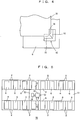
FIG. 1 is a plan view showing an arrangement of support devices according to an embodiment. -
FIG. 2 is a cross-sectional view of a main portion of the support device taken along line II-II inFIG. 1 where a first article is placed on the support device. -
FIG. 3 is a cross-sectional view of a main portion of the support device taken along line III-III inFIG. 1 where a second article is placed on the support device. -
FIG. 4 is a partial plan view showing positioning of the second article. -
FIG. 5 is a plan view of a stocker where the support devices according to the embodiment are used. - The following describes an optimum embodiment for carrying out the present invention. The scope of the present invention is based on the recitation of the claims, and is intended to be determined in accordance with the understanding of a person skilled in the art with reference to the recitation of this description and well-known techniques in the field of the present invention.
-
FIGS. 1 to 5 show support devices 2 according to an embodiment and astocker 50 in which thesupport devices 2 are used.FIG. 1 shows thesupport devices 2 arranged in the stocker. Thesupport devices 2 are attached tovertical supports 4 of thestocker 50 and are vertically and laterally arranged. Eachsupport device 2 has a plate-like shape and has anopening 6 on a side opposite to thevertical supports 4, a placingsurface 8 on the opposite two sides of theopening 6, and a placingsurface 9 on thevertical support 4 side. The placingsurface 8 is provided with apin 10 and atapered piece 12, and thus thesupport device 2 includes a pair ofpins 10 and a pair oftapered pieces 12. In this description, thevertical support 4 side is referred to as a back side, a front end side of theopening 6 is referred to as a front side, and thepin 10 is located on the back side with respect to thetapered piece 12 and near theopening 6. Three ormore pins 10 and three or moretapered pieces 12 may be provided. In particular, thetapered pieces 12 are further provided at two positions on the back side of thesupport device 2 in addition to the two positions on the front side thereof, and corners of anarticle 30 are positioned by thetapered pieces 12 at the four positions, thus obtaining improved accurate positioning of thearticle 30. However, as in the embodiment, thetapered pieces 12 may be provided at only two positions on the front side of thesupport device 2. - 20 indicates a first article, and 30 indicates a second article. The first article 20 (referred to as merely "
article 20" hereinafter) is a container for accommodating a 300 mm semiconductor wafer, for example, and the second article 30 (referred to as merely "article 30" hereinafter) is a container for accommodating a 450 mm semiconductor wafer, for example. Thearticles article 30 is larger than that of thearticle 20. Thearticle 20 is positioned by thepins 10 without interfering with thetapered pieces 12, and thearticle 30 is positioned by thetapered pieces 12 without interfering with thepins 10. 21 and 31 indicate top portions of thearticles top portions articles articles - The
articles positioning grooves articles grooves grooves articles grooves articles support device 2. Therefore, thearticle 20 is positioned with thepins 10 on the placing surfaces 8 being engaged with holes provided in the bottom portion of thearticle 20. Moreover, as for thearticle 30,corners 36 of thearticle 30 are positioned by the taperedpieces 12 on the placing surfaces 8. -
FIG. 2 shows positioning of thearticle 20. Thearticle 20, which is a container for a 300 mm wafer, is generally provided with a pair ofholes 26 for being engaged with pins that are called forklift pins. Thepins 10 are provided so as to be engaged with theholes 26. Positions at which thepins 10 are provided and positions at which thearticle 30 is placed on thesupport device 2 are selected so that thepins 10 are located in thepositioning grooves 34 of thearticle 30 and do not interfere with thearticle 30.FIG. 3 shows this state. 25 and 35 indicate shelves in thearticles shelves - Since the
positioning grooves 34 of thearticle 30 are used to avoid interference with thepins 10, a pair ofcorners 36 on thedoor 32 side of thearticle 30 is positioned by the taperedpieces 12.FIG. 4 shows this state. Thetapered pieces 12 each include atapered surface 14 that is inclined in a lateral direction and atapered surface 15 that lowers from the front side to the back side. Thearticle 30 is positioned by guiding the pair ofcorners 36 by a pair of left and righttapered pieces 12. In addition to thecorners 36, any recessed and projecting portions on the outer perimeter of the bottom portion of thearticle 30 can be used for positioning. - The
support device 2 is usable in any application for placing thearticles support device 2 is used as a support member in thestocker 50, for example, thestocker 50 is usable in common for 300 mm wafers and 450 mm wafers. Atransport device 52 moves in acentral transport space 51, and loads and unloads the articles in and from thesupport devices 2. Thesupport devices 2 are arranged on two sides of thetransport space 51 over a plurality of layers. Although thetransport device 52 may be any type of transport device, for example, amast 56 is provided on avehicle 53, and a driver for atransfer hand 54 is moved up and down. Thehand 54 may be used in common for thearticles respective articles respective articles -
- 2 Support device
- 4 Vertical support
- 6 Opening
- 8, 9 Placing surface
- 10 Pin
- 12 Tapered piece
- 14, 15 Tapered surface
- 20 First article
- 30 Second article
- 21, 31 Top portion
- 22, 32 Door
- 24, 34 Positioning groove
- 25, 35 Shelf
- 26 Hole
- 36 Corner
- 50 Stocker
- 51 Transport space
- 52 Transport device
- 53 Vehicle
- 54 Hand
- 56 Mast
- W1, W2 Semiconductor wafer
Claims (8)
- An article support device supporting a plurality of types of articles thereon comprising:a placing surface configured to support both a first article and a second article having a larger bottom portion than a bottom portion of said first article thereon;a first positioning member protruding from said placing surface for positioning the bottom portion of said first article; anda second positioning member protruding from said placing surface for positioning said second article,wherein said first positioning member is arranged at a position where interference with said second article is prevented, when said second article is positioned on the placing surface by said second positioning member, andwherein said second positioning member is arranged at a position where interference with said first article is prevented, when said first article is positioned on the placing surface by said first positioning member.
- The article support device according to claim 1,
wherein said first positioning member comprises at least a pair of pins protruding from the placing surface, and configured to be engaged with holes in the bottom portion of said first article, to enter recessed portions in the bottom portion of said second article, and not to come into contact with the second article. - The article support device according to claim 1,
wherein said second positioning member comprises at least a pair of guiding members protruding from the placing surface configured to guide an outer perimeter of the bottom portion of said second article. - The article support device according to claim 3,
wherein said first positioning member comprises at least a pair of pins protruding from the placing surface, and configured to be engaged with holes in the bottom portion of said first article, to enter positioning grooves provided radially in the bottom portion of said second article, and not to come into contact with said second article. - The article support device according to claim 4,
wherein each of the pair of guiding members includes a pair of tapered surfaces different in inclination direction, and the pairs of tapered surfaces are configured to guide corners of the outer perimeter of the bottom portion of said second article. - The article support device according to claim 5,
wherein both said first article and said second article are containers for accommodating semiconductor wafers, and said second article is configured to accommodate semiconductor wafers having a larger diameter compared with those accommodated in said first article. - The article support device according to claim 6,
wherein said first article is provided with positioning grooves radially in the bottom portion thereof, and
the article support device is configured to position the bottom portion of said first article and the bottom portion of said second article without coming into contact with the positioning grooves of said first article nor the positioning grooves of said second article. - A method for placing two types of articles on a support device,
the support device comprising: a placing surface configured to support both a first article and a second article having a larger bottom portion than a bottom portion of said first article thereon; a first positioning member; and a second positioning member, both protruding from said placing surface,
the method comprising:a step for positioning the first article by the first positioning member and placing the first article on the placing surface while interference between the second positioning member and the first article is avoided, anda step for positioning the second article by the second positioning member and placing the second article on the placing surface while interference between the first positioning member and the second article is avoided.
Applications Claiming Priority (2)
| Application Number | Priority Date | Filing Date | Title |
|---|---|---|---|
| JP2013201778 | 2013-09-27 | ||
| PCT/JP2014/069019 WO2015045583A1 (en) | 2013-09-27 | 2014-07-17 | Article support device and method for placing two types of articles on support device |
Publications (3)
| Publication Number | Publication Date |
|---|---|
| EP3050825A1 true EP3050825A1 (en) | 2016-08-03 |
| EP3050825A4 EP3050825A4 (en) | 2017-04-19 |
| EP3050825B1 EP3050825B1 (en) | 2021-09-01 |
Family
ID=52742740
Family Applications (1)
| Application Number | Title | Priority Date | Filing Date |
|---|---|---|---|
| EP14847792.0A Active EP3050825B1 (en) | 2013-09-27 | 2014-07-17 | Storage system and method for placing two types of articles on a support device |
Country Status (8)
| Country | Link |
|---|---|
| US (1) | US9664335B2 (en) |
| EP (1) | EP3050825B1 (en) |
| JP (1) | JP6052642B2 (en) |
| KR (1) | KR101697202B1 (en) |
| CN (1) | CN105683064B (en) |
| SG (1) | SG11201600344RA (en) |
| TW (1) | TWI582887B (en) |
| WO (1) | WO2015045583A1 (en) |
Families Citing this family (7)
| Publication number | Priority date | Publication date | Assignee | Title |
|---|---|---|---|---|
| JP6332133B2 (en) * | 2015-05-14 | 2018-05-30 | 株式会社ダイフク | Container transfer equipment |
| JP6493339B2 (en) * | 2016-08-26 | 2019-04-03 | 村田機械株式会社 | Transport container and method for transferring contents |
| JP6794898B2 (en) * | 2017-03-29 | 2020-12-02 | 株式会社ダイフク | Storage rack |
| JP6801640B2 (en) * | 2017-12-21 | 2020-12-16 | 株式会社ダイフク | Storage shelves and goods storage equipment |
| CN109051481B (en) * | 2018-07-24 | 2020-05-08 | 杭州星程科技有限公司 | Logistics commodity sorting method |
| JP7222378B2 (en) * | 2020-05-13 | 2023-02-15 | 株式会社ダイフク | Article conveying device |
| KR102822032B1 (en) * | 2024-09-06 | 2025-06-19 | 주식회사 알앤디어스 | Side storage applicable to wafer chamber of various size |
Family Cites Families (13)
| Publication number | Priority date | Publication date | Assignee | Title |
|---|---|---|---|---|
| CA2007003C (en) * | 1988-08-01 | 1994-10-11 | Irvin Dale Bond | Parts stacking pallet |
| JP4050806B2 (en) * | 1997-06-26 | 2008-02-20 | ゼオン化成株式会社 | Double box container |
| JP3941194B2 (en) * | 1997-11-28 | 2007-07-04 | 神鋼電機株式会社 | Carrier mounting device |
| TWI237305B (en) | 1998-02-04 | 2005-08-01 | Nikon Corp | Exposure apparatus and positioning apparatus of substrate receiving cassette |
| JP2002002909A (en) * | 2000-06-19 | 2002-01-09 | Shinko Electric Co Ltd | How to check stocker robot teaching |
| KR100481307B1 (en) * | 2001-11-08 | 2005-04-07 | 삼성전자주식회사 | Cassette table for semiconductor fabrication apparatus |
| JP2003174068A (en) * | 2001-12-05 | 2003-06-20 | Oputeikon:Kk | Device for confirming seating of wafer carrying container |
| JP4474922B2 (en) * | 2004-01-07 | 2010-06-09 | シンフォニアテクノロジー株式会社 | Load port device |
| JP4200387B2 (en) | 2006-04-14 | 2008-12-24 | 村田機械株式会社 | Transport system |
| CN101578700B (en) * | 2006-08-18 | 2012-11-14 | 布鲁克斯自动化公司 | Reduced capacity carrier, transport, load port, buffer system |
| US8016113B2 (en) * | 2008-09-16 | 2011-09-13 | Plastic Systems, Inc. | Storage system with improved pole securement system |
| JP2011187539A (en) * | 2010-03-05 | 2011-09-22 | Sinfonia Technology Co Ltd | Gas charging apparatus, gas discharging apparatus, gas charging method, and gas discharging method |
| CN202268335U (en) | 2011-09-07 | 2012-06-06 | 承澔科技股份有限公司 | Carrying mechanism capable of assembling wafer cassettes of different sizes |
-
2014
- 2014-07-17 CN CN201480052704.1A patent/CN105683064B/en active Active
- 2014-07-17 EP EP14847792.0A patent/EP3050825B1/en active Active
- 2014-07-17 KR KR1020167010049A patent/KR101697202B1/en active Active
- 2014-07-17 WO PCT/JP2014/069019 patent/WO2015045583A1/en not_active Ceased
- 2014-07-17 US US15/021,388 patent/US9664335B2/en active Active
- 2014-07-17 SG SG11201600344RA patent/SG11201600344RA/en unknown
- 2014-07-17 JP JP2015538983A patent/JP6052642B2/en active Active
- 2014-09-26 TW TW103133484A patent/TWI582887B/en active
Also Published As
| Publication number | Publication date |
|---|---|
| KR101697202B1 (en) | 2017-01-17 |
| SG11201600344RA (en) | 2016-04-28 |
| WO2015045583A1 (en) | 2015-04-02 |
| JPWO2015045583A1 (en) | 2017-03-09 |
| CN105683064B (en) | 2018-02-09 |
| TWI582887B (en) | 2017-05-11 |
| US20160223136A1 (en) | 2016-08-04 |
| KR20160060086A (en) | 2016-05-27 |
| CN105683064A (en) | 2016-06-15 |
| EP3050825B1 (en) | 2021-09-01 |
| JP6052642B2 (en) | 2016-12-27 |
| EP3050825A4 (en) | 2017-04-19 |
| TW201526144A (en) | 2015-07-01 |
| US9664335B2 (en) | 2017-05-30 |
Similar Documents
| Publication | Publication Date | Title |
|---|---|---|
| US9664335B2 (en) | Article support device and method for placing two types of articles on support device | |
| US9142437B2 (en) | System for separately handling different size FOUPs | |
| EP3053854A1 (en) | Storage warehouse | |
| KR102450289B1 (en) | Vessel conveying equipment and vessel conveying equipment | |
| US11034519B2 (en) | Article placement apparatus, stocker provided therewith, and transport vehicle system | |
| JP2016216137A5 (en) | ||
| US10287096B2 (en) | Article support rack | |
| US20230061872A1 (en) | Wafer storage system | |
| KR102172064B1 (en) | Unit for buffering a carrier and apparatus for transferring a carrier having the unit | |
| JP7043957B2 (en) | Goods storage shelf | |
| US9927488B2 (en) | Package transfer unit and package management apparatus including the same | |
| JP6233340B2 (en) | Stocker and article supporting method | |
| KR102385796B1 (en) | Article storage facility | |
| US11923224B2 (en) | Carrier positioning member and carrier placement platform | |
| KR102207870B1 (en) | Unit for supporting a gripping part and apparatus for transferring a carrier having the unit | |
| JP2017195279A (en) | Container support shelf | |
| CN110520371B (en) | High density stocker | |
| KR102098791B1 (en) | Stocker | |
| US8858150B2 (en) | Door detection system | |
| JP2024039392A (en) | Entrance/exit structure, transportation device, and method of transferring goods | |
| JP2017052540A (en) | container |
Legal Events
| Date | Code | Title | Description |
|---|---|---|---|
| PUAI | Public reference made under article 153(3) epc to a published international application that has entered the european phase |
Free format text: ORIGINAL CODE: 0009012 |
|
| 17P | Request for examination filed |
Effective date: 20160125 |
|
| AK | Designated contracting states |
Kind code of ref document: A1 Designated state(s): AL AT BE BG CH CY CZ DE DK EE ES FI FR GB GR HR HU IE IS IT LI LT LU LV MC MK MT NL NO PL PT RO RS SE SI SK SM TR |
|
| AX | Request for extension of the european patent |
Extension state: BA ME |
|
| DAX | Request for extension of the european patent (deleted) | ||
| REG | Reference to a national code |
Ref country code: DE Ref legal event code: R079 Ref document number: 602014079893 Country of ref document: DE Free format text: PREVIOUS MAIN CLASS: B65G0001140000 Ipc: H01L0021677000 |
|
| A4 | Supplementary search report drawn up and despatched |
Effective date: 20170322 |
|
| RIC1 | Information provided on ipc code assigned before grant |
Ipc: H01L 21/673 20060101ALI20170316BHEP Ipc: F16M 13/02 20060101ALI20170316BHEP Ipc: H01L 21/677 20060101AFI20170316BHEP |
|
| STAA | Information on the status of an ep patent application or granted ep patent |
Free format text: STATUS: EXAMINATION IS IN PROGRESS |
|
| 17Q | First examination report despatched |
Effective date: 20201104 |
|
| GRAP | Despatch of communication of intention to grant a patent |
Free format text: ORIGINAL CODE: EPIDOSNIGR1 |
|
| STAA | Information on the status of an ep patent application or granted ep patent |
Free format text: STATUS: GRANT OF PATENT IS INTENDED |
|
| INTG | Intention to grant announced |
Effective date: 20210507 |
|
| GRAS | Grant fee paid |
Free format text: ORIGINAL CODE: EPIDOSNIGR3 |
|
| GRAA | (expected) grant |
Free format text: ORIGINAL CODE: 0009210 |
|
| STAA | Information on the status of an ep patent application or granted ep patent |
Free format text: STATUS: THE PATENT HAS BEEN GRANTED |
|
| AK | Designated contracting states |
Kind code of ref document: B1 Designated state(s): AL AT BE BG CH CY CZ DE DK EE ES FI FR GB GR HR HU IE IS IT LI LT LU LV MC MK MT NL NO PL PT RO RS SE SI SK SM TR |
|
| REG | Reference to a national code |
Ref country code: GB Ref legal event code: FG4D |
|
| REG | Reference to a national code |
Ref country code: CH Ref legal event code: EP Ref country code: AT Ref legal event code: REF Ref document number: 1427112 Country of ref document: AT Kind code of ref document: T Effective date: 20210915 |
|
| REG | Reference to a national code |
Ref country code: DE Ref legal event code: R096 Ref document number: 602014079893 Country of ref document: DE |
|
| REG | Reference to a national code |
Ref country code: IE Ref legal event code: FG4D |
|
| REG | Reference to a national code |
Ref country code: LT Ref legal event code: MG9D |
|
| REG | Reference to a national code |
Ref country code: NL Ref legal event code: MP Effective date: 20210901 |
|
| PG25 | Lapsed in a contracting state [announced via postgrant information from national office to epo] |
Ref country code: HR Free format text: LAPSE BECAUSE OF FAILURE TO SUBMIT A TRANSLATION OF THE DESCRIPTION OR TO PAY THE FEE WITHIN THE PRESCRIBED TIME-LIMIT Effective date: 20210901 Ref country code: SE Free format text: LAPSE BECAUSE OF FAILURE TO SUBMIT A TRANSLATION OF THE DESCRIPTION OR TO PAY THE FEE WITHIN THE PRESCRIBED TIME-LIMIT Effective date: 20210901 Ref country code: RS Free format text: LAPSE BECAUSE OF FAILURE TO SUBMIT A TRANSLATION OF THE DESCRIPTION OR TO PAY THE FEE WITHIN THE PRESCRIBED TIME-LIMIT Effective date: 20210901 Ref country code: ES Free format text: LAPSE BECAUSE OF FAILURE TO SUBMIT A TRANSLATION OF THE DESCRIPTION OR TO PAY THE FEE WITHIN THE PRESCRIBED TIME-LIMIT Effective date: 20210901 Ref country code: FI Free format text: LAPSE BECAUSE OF FAILURE TO SUBMIT A TRANSLATION OF THE DESCRIPTION OR TO PAY THE FEE WITHIN THE PRESCRIBED TIME-LIMIT Effective date: 20210901 Ref country code: NO Free format text: LAPSE BECAUSE OF FAILURE TO SUBMIT A TRANSLATION OF THE DESCRIPTION OR TO PAY THE FEE WITHIN THE PRESCRIBED TIME-LIMIT Effective date: 20211201 Ref country code: LT Free format text: LAPSE BECAUSE OF FAILURE TO SUBMIT A TRANSLATION OF THE DESCRIPTION OR TO PAY THE FEE WITHIN THE PRESCRIBED TIME-LIMIT Effective date: 20210901 Ref country code: BG Free format text: LAPSE BECAUSE OF FAILURE TO SUBMIT A TRANSLATION OF THE DESCRIPTION OR TO PAY THE FEE WITHIN THE PRESCRIBED TIME-LIMIT Effective date: 20211201 |
|
| REG | Reference to a national code |
Ref country code: AT Ref legal event code: MK05 Ref document number: 1427112 Country of ref document: AT Kind code of ref document: T Effective date: 20210901 |
|
| PG25 | Lapsed in a contracting state [announced via postgrant information from national office to epo] |
Ref country code: PL Free format text: LAPSE BECAUSE OF FAILURE TO SUBMIT A TRANSLATION OF THE DESCRIPTION OR TO PAY THE FEE WITHIN THE PRESCRIBED TIME-LIMIT Effective date: 20210901 Ref country code: LV Free format text: LAPSE BECAUSE OF FAILURE TO SUBMIT A TRANSLATION OF THE DESCRIPTION OR TO PAY THE FEE WITHIN THE PRESCRIBED TIME-LIMIT Effective date: 20210901 Ref country code: GR Free format text: LAPSE BECAUSE OF FAILURE TO SUBMIT A TRANSLATION OF THE DESCRIPTION OR TO PAY THE FEE WITHIN THE PRESCRIBED TIME-LIMIT Effective date: 20211202 |
|
| PG25 | Lapsed in a contracting state [announced via postgrant information from national office to epo] |
Ref country code: AT Free format text: LAPSE BECAUSE OF FAILURE TO SUBMIT A TRANSLATION OF THE DESCRIPTION OR TO PAY THE FEE WITHIN THE PRESCRIBED TIME-LIMIT Effective date: 20210901 |
|
| PG25 | Lapsed in a contracting state [announced via postgrant information from national office to epo] |
Ref country code: IS Free format text: LAPSE BECAUSE OF FAILURE TO SUBMIT A TRANSLATION OF THE DESCRIPTION OR TO PAY THE FEE WITHIN THE PRESCRIBED TIME-LIMIT Effective date: 20220101 Ref country code: SM Free format text: LAPSE BECAUSE OF FAILURE TO SUBMIT A TRANSLATION OF THE DESCRIPTION OR TO PAY THE FEE WITHIN THE PRESCRIBED TIME-LIMIT Effective date: 20210901 Ref country code: SK Free format text: LAPSE BECAUSE OF FAILURE TO SUBMIT A TRANSLATION OF THE DESCRIPTION OR TO PAY THE FEE WITHIN THE PRESCRIBED TIME-LIMIT Effective date: 20210901 Ref country code: RO Free format text: LAPSE BECAUSE OF FAILURE TO SUBMIT A TRANSLATION OF THE DESCRIPTION OR TO PAY THE FEE WITHIN THE PRESCRIBED TIME-LIMIT Effective date: 20210901 Ref country code: PT Free format text: LAPSE BECAUSE OF FAILURE TO SUBMIT A TRANSLATION OF THE DESCRIPTION OR TO PAY THE FEE WITHIN THE PRESCRIBED TIME-LIMIT Effective date: 20220103 Ref country code: NL Free format text: LAPSE BECAUSE OF FAILURE TO SUBMIT A TRANSLATION OF THE DESCRIPTION OR TO PAY THE FEE WITHIN THE PRESCRIBED TIME-LIMIT Effective date: 20210901 Ref country code: EE Free format text: LAPSE BECAUSE OF FAILURE TO SUBMIT A TRANSLATION OF THE DESCRIPTION OR TO PAY THE FEE WITHIN THE PRESCRIBED TIME-LIMIT Effective date: 20210901 Ref country code: CZ Free format text: LAPSE BECAUSE OF FAILURE TO SUBMIT A TRANSLATION OF THE DESCRIPTION OR TO PAY THE FEE WITHIN THE PRESCRIBED TIME-LIMIT Effective date: 20210901 Ref country code: AL Free format text: LAPSE BECAUSE OF FAILURE TO SUBMIT A TRANSLATION OF THE DESCRIPTION OR TO PAY THE FEE WITHIN THE PRESCRIBED TIME-LIMIT Effective date: 20210901 |
|
| REG | Reference to a national code |
Ref country code: DE Ref legal event code: R097 Ref document number: 602014079893 Country of ref document: DE |
|
| PLBE | No opposition filed within time limit |
Free format text: ORIGINAL CODE: 0009261 |
|
| STAA | Information on the status of an ep patent application or granted ep patent |
Free format text: STATUS: NO OPPOSITION FILED WITHIN TIME LIMIT |
|
| PG25 | Lapsed in a contracting state [announced via postgrant information from national office to epo] |
Ref country code: IT Free format text: LAPSE BECAUSE OF FAILURE TO SUBMIT A TRANSLATION OF THE DESCRIPTION OR TO PAY THE FEE WITHIN THE PRESCRIBED TIME-LIMIT Effective date: 20210901 Ref country code: DK Free format text: LAPSE BECAUSE OF FAILURE TO SUBMIT A TRANSLATION OF THE DESCRIPTION OR TO PAY THE FEE WITHIN THE PRESCRIBED TIME-LIMIT Effective date: 20210901 |
|
| 26N | No opposition filed |
Effective date: 20220602 |
|
| PG25 | Lapsed in a contracting state [announced via postgrant information from national office to epo] |
Ref country code: SI Free format text: LAPSE BECAUSE OF FAILURE TO SUBMIT A TRANSLATION OF THE DESCRIPTION OR TO PAY THE FEE WITHIN THE PRESCRIBED TIME-LIMIT Effective date: 20210901 |
|
| PG25 | Lapsed in a contracting state [announced via postgrant information from national office to epo] |
Ref country code: MC Free format text: LAPSE BECAUSE OF FAILURE TO SUBMIT A TRANSLATION OF THE DESCRIPTION OR TO PAY THE FEE WITHIN THE PRESCRIBED TIME-LIMIT Effective date: 20210901 |
|
| REG | Reference to a national code |
Ref country code: CH Ref legal event code: PL |
|
| GBPC | Gb: european patent ceased through non-payment of renewal fee |
Effective date: 20220717 |
|
| REG | Reference to a national code |
Ref country code: BE Ref legal event code: MM Effective date: 20220731 |
|
| PG25 | Lapsed in a contracting state [announced via postgrant information from national office to epo] |
Ref country code: LU Free format text: LAPSE BECAUSE OF NON-PAYMENT OF DUE FEES Effective date: 20220717 Ref country code: LI Free format text: LAPSE BECAUSE OF NON-PAYMENT OF DUE FEES Effective date: 20220731 Ref country code: FR Free format text: LAPSE BECAUSE OF NON-PAYMENT OF DUE FEES Effective date: 20220731 Ref country code: CH Free format text: LAPSE BECAUSE OF NON-PAYMENT OF DUE FEES Effective date: 20220731 |
|
| PG25 | Lapsed in a contracting state [announced via postgrant information from national office to epo] |
Ref country code: GB Free format text: LAPSE BECAUSE OF NON-PAYMENT OF DUE FEES Effective date: 20220717 Ref country code: BE Free format text: LAPSE BECAUSE OF NON-PAYMENT OF DUE FEES Effective date: 20220731 |
|
| PG25 | Lapsed in a contracting state [announced via postgrant information from national office to epo] |
Ref country code: HU Free format text: LAPSE BECAUSE OF FAILURE TO SUBMIT A TRANSLATION OF THE DESCRIPTION OR TO PAY THE FEE WITHIN THE PRESCRIBED TIME-LIMIT; INVALID AB INITIO Effective date: 20140717 |
|
| PG25 | Lapsed in a contracting state [announced via postgrant information from national office to epo] |
Ref country code: MK Free format text: LAPSE BECAUSE OF FAILURE TO SUBMIT A TRANSLATION OF THE DESCRIPTION OR TO PAY THE FEE WITHIN THE PRESCRIBED TIME-LIMIT Effective date: 20210901 Ref country code: CY Free format text: LAPSE BECAUSE OF FAILURE TO SUBMIT A TRANSLATION OF THE DESCRIPTION OR TO PAY THE FEE WITHIN THE PRESCRIBED TIME-LIMIT Effective date: 20210901 |
|
| PG25 | Lapsed in a contracting state [announced via postgrant information from national office to epo] |
Ref country code: MT Free format text: LAPSE BECAUSE OF FAILURE TO SUBMIT A TRANSLATION OF THE DESCRIPTION OR TO PAY THE FEE WITHIN THE PRESCRIBED TIME-LIMIT Effective date: 20210901 |
|
| PGFP | Annual fee paid to national office [announced via postgrant information from national office to epo] |
Ref country code: IE Payment date: 20250623 Year of fee payment: 12 |
|
| PGFP | Annual fee paid to national office [announced via postgrant information from national office to epo] |
Ref country code: DE Payment date: 20250620 Year of fee payment: 12 |
|
| REG | Reference to a national code |
Ref country code: DE Ref legal event code: R079 Ref document number: 602014079893 Country of ref document: DE Free format text: PREVIOUS MAIN CLASS: H01L0021677000 Ipc: H10P0072300000 |
|
| PG25 | Lapsed in a contracting state [announced via postgrant information from national office to epo] |
Ref country code: TR Free format text: LAPSE BECAUSE OF FAILURE TO SUBMIT A TRANSLATION OF THE DESCRIPTION OR TO PAY THE FEE WITHIN THE PRESCRIBED TIME-LIMIT Effective date: 20210901 |