EP3050737A1 - Système de présence d'opérateur - Google Patents
Système de présence d'opérateur Download PDFInfo
- Publication number
- EP3050737A1 EP3050737A1 EP16152695.9A EP16152695A EP3050737A1 EP 3050737 A1 EP3050737 A1 EP 3050737A1 EP 16152695 A EP16152695 A EP 16152695A EP 3050737 A1 EP3050737 A1 EP 3050737A1
- Authority
- EP
- European Patent Office
- Prior art keywords
- detector
- operator
- floor
- emitter
- receiver
- Prior art date
- Legal status (The legal status is an assumption and is not a legal conclusion. Google has not performed a legal analysis and makes no representation as to the accuracy of the status listed.)
- Granted
Links
Images


Classifications
-
- B—PERFORMING OPERATIONS; TRANSPORTING
- B60—VEHICLES IN GENERAL
- B60K—ARRANGEMENT OR MOUNTING OF PROPULSION UNITS OR OF TRANSMISSIONS IN VEHICLES; ARRANGEMENT OR MOUNTING OF PLURAL DIVERSE PRIME-MOVERS IN VEHICLES; AUXILIARY DRIVES FOR VEHICLES; INSTRUMENTATION OR DASHBOARDS FOR VEHICLES; ARRANGEMENTS IN CONNECTION WITH COOLING, AIR INTAKE, GAS EXHAUST OR FUEL SUPPLY OF PROPULSION UNITS IN VEHICLES
- B60K28/00—Safety devices for propulsion-unit control, specially adapted for, or arranged in, vehicles, e.g. preventing fuel supply or ignition in the event of potentially dangerous conditions
- B60K28/02—Safety devices for propulsion-unit control, specially adapted for, or arranged in, vehicles, e.g. preventing fuel supply or ignition in the event of potentially dangerous conditions responsive to conditions relating to the driver
- B60K28/04—Safety devices for propulsion-unit control, specially adapted for, or arranged in, vehicles, e.g. preventing fuel supply or ignition in the event of potentially dangerous conditions responsive to conditions relating to the driver responsive to presence or absence of the driver, e.g. to weight or lack thereof
-
- B—PERFORMING OPERATIONS; TRANSPORTING
- B60—VEHICLES IN GENERAL
- B60W—CONJOINT CONTROL OF VEHICLE SUB-UNITS OF DIFFERENT TYPE OR DIFFERENT FUNCTION; CONTROL SYSTEMS SPECIALLY ADAPTED FOR HYBRID VEHICLES; ROAD VEHICLE DRIVE CONTROL SYSTEMS FOR PURPOSES NOT RELATED TO THE CONTROL OF A PARTICULAR SUB-UNIT
- B60W40/00—Estimation or calculation of non-directly measurable driving parameters for road vehicle drive control systems not related to the control of a particular sub unit, e.g. by using mathematical models
- B60W40/08—Estimation or calculation of non-directly measurable driving parameters for road vehicle drive control systems not related to the control of a particular sub unit, e.g. by using mathematical models related to drivers or passengers
-
- B—PERFORMING OPERATIONS; TRANSPORTING
- B60—VEHICLES IN GENERAL
- B60R—VEHICLES, VEHICLE FITTINGS, OR VEHICLE PARTS, NOT OTHERWISE PROVIDED FOR
- B60R21/00—Arrangements or fittings on vehicles for protecting or preventing injuries to occupants or pedestrians in case of accidents or other traffic risks
- B60R21/01—Electrical circuits for triggering passive safety arrangements, e.g. airbags, safety belt tighteners, in case of vehicle accidents or impending vehicle accidents
- B60R21/015—Electrical circuits for triggering passive safety arrangements, e.g. airbags, safety belt tighteners, in case of vehicle accidents or impending vehicle accidents including means for detecting the presence or position of passengers, passenger seats or child seats, and the related safety parameters therefor, e.g. speed or timing of airbag inflation in relation to occupant position or seat belt use
- B60R21/01512—Passenger detection systems
- B60R21/01516—Passenger detection systems using force or pressure sensing means
-
- B—PERFORMING OPERATIONS; TRANSPORTING
- B60—VEHICLES IN GENERAL
- B60R—VEHICLES, VEHICLE FITTINGS, OR VEHICLE PARTS, NOT OTHERWISE PROVIDED FOR
- B60R16/00—Electric or fluid circuits specially adapted for vehicles and not otherwise provided for; Arrangement of elements of electric or fluid circuits specially adapted for vehicles and not otherwise provided for
- B60R16/02—Electric or fluid circuits specially adapted for vehicles and not otherwise provided for; Arrangement of elements of electric or fluid circuits specially adapted for vehicles and not otherwise provided for electric constitutive elements
- B60R16/023—Electric or fluid circuits specially adapted for vehicles and not otherwise provided for; Arrangement of elements of electric or fluid circuits specially adapted for vehicles and not otherwise provided for electric constitutive elements for transmission of signals between vehicle parts or subsystems
-
- B—PERFORMING OPERATIONS; TRANSPORTING
- B66—HOISTING; LIFTING; HAULING
- B66F—HOISTING, LIFTING, HAULING OR PUSHING, NOT OTHERWISE PROVIDED FOR, e.g. DEVICES WHICH APPLY A LIFTING OR PUSHING FORCE DIRECTLY TO THE SURFACE OF A LOAD
- B66F17/00—Safety devices, e.g. for limiting or indicating lifting force
- B66F17/003—Safety devices, e.g. for limiting or indicating lifting force for fork-lift trucks
-
- B—PERFORMING OPERATIONS; TRANSPORTING
- B66—HOISTING; LIFTING; HAULING
- B66F—HOISTING, LIFTING, HAULING OR PUSHING, NOT OTHERWISE PROVIDED FOR, e.g. DEVICES WHICH APPLY A LIFTING OR PUSHING FORCE DIRECTLY TO THE SURFACE OF A LOAD
- B66F9/00—Devices for lifting or lowering bulky or heavy goods for loading or unloading purposes
- B66F9/06—Devices for lifting or lowering bulky or heavy goods for loading or unloading purposes movable, with their loads, on wheels or the like, e.g. fork-lift trucks
- B66F9/075—Constructional features or details
- B66F9/0759—Details of operating station, e.g. seats, levers, operator platforms, cabin suspension
-
- B—PERFORMING OPERATIONS; TRANSPORTING
- B60—VEHICLES IN GENERAL
- B60W—CONJOINT CONTROL OF VEHICLE SUB-UNITS OF DIFFERENT TYPE OR DIFFERENT FUNCTION; CONTROL SYSTEMS SPECIALLY ADAPTED FOR HYBRID VEHICLES; ROAD VEHICLE DRIVE CONTROL SYSTEMS FOR PURPOSES NOT RELATED TO THE CONTROL OF A PARTICULAR SUB-UNIT
- B60W40/00—Estimation or calculation of non-directly measurable driving parameters for road vehicle drive control systems not related to the control of a particular sub unit, e.g. by using mathematical models
- B60W40/08—Estimation or calculation of non-directly measurable driving parameters for road vehicle drive control systems not related to the control of a particular sub unit, e.g. by using mathematical models related to drivers or passengers
- B60W2040/0881—Seat occupation; Driver or passenger presence
-
- B—PERFORMING OPERATIONS; TRANSPORTING
- B60—VEHICLES IN GENERAL
- B60W—CONJOINT CONTROL OF VEHICLE SUB-UNITS OF DIFFERENT TYPE OR DIFFERENT FUNCTION; CONTROL SYSTEMS SPECIALLY ADAPTED FOR HYBRID VEHICLES; ROAD VEHICLE DRIVE CONTROL SYSTEMS FOR PURPOSES NOT RELATED TO THE CONTROL OF A PARTICULAR SUB-UNIT
- B60W2300/00—Indexing codes relating to the type of vehicle
- B60W2300/12—Trucks; Load vehicles
- B60W2300/121—Fork lift trucks, Clarks
-
- B—PERFORMING OPERATIONS; TRANSPORTING
- B60—VEHICLES IN GENERAL
- B60W—CONJOINT CONTROL OF VEHICLE SUB-UNITS OF DIFFERENT TYPE OR DIFFERENT FUNCTION; CONTROL SYSTEMS SPECIALLY ADAPTED FOR HYBRID VEHICLES; ROAD VEHICLE DRIVE CONTROL SYSTEMS FOR PURPOSES NOT RELATED TO THE CONTROL OF A PARTICULAR SUB-UNIT
- B60W2420/00—Indexing codes relating to the type of sensors based on the principle of their operation
- B60W2420/40—Photo, light or radio wave sensitive means, e.g. infrared sensors
-
- B—PERFORMING OPERATIONS; TRANSPORTING
- B60—VEHICLES IN GENERAL
- B60Y—INDEXING SCHEME RELATING TO ASPECTS CROSS-CUTTING VEHICLE TECHNOLOGY
- B60Y2200/00—Type of vehicle
- B60Y2200/10—Road Vehicles
- B60Y2200/15—Fork lift trucks, Industrial trucks
Definitions
- the disclosure pertains to detecting a vehicle operator's presence and enabling, disabling, or not enabling one or more vehicle functions based on such detection, for example, to reinforce operator training.
- Disclosed systems and methods detect when an operator is or is not standing properly in an operator's compartment, preferably in a manner consistent with the driver's training.
- the entire vehicle, or one or more functions of the vehicle may be enabled, limited, or disabled depending on whether an operator's position on a driving platform is consistent with the training received by the operator.
- a drive function of an end-rider lift truck may be disabled when a detection device or system associated with such a vehicle detects there is no operator on the drive platform or a driver on the drive platform is not standing with both feet in a predetermined configuration; or multiple functions may be disabled, such as a drive function and a hoist function.
- a vehicle equipped with an operator presence detector comprises a first detector or first collection of detectors located and configured to detect an object positioned over or in the threshold plane to the operator compartment; a second detector or second collection of detectors located and configured to detect an operator's left lower extremity when the left lower extremity is located in the operator compartment; and a third detector or third collection of detectors located and configured to detect an operator's right lower extremity when the right lower extremity is located in the operator compartment.
- the second detector, or second detector collection, and the third detector, or third detector collection are positioned such that an operator cannot cause the second detector, or second detector collection, to detect both a left lower extremity and a right lower extremity at the same time and cannot cause the third detector, or third detector collection, to detect both a right lower extremity and a left lower extremity at the same time.
- the present inventors have recognized that operators of industrial vehicles equipped with a standing operator compartment commonly utilize a five-point stance, for example, both feet on the floor of an operator compartment, one hand on a steering device, one hand on an interior portion of the operator compartment, and a portion of the back pressed against an interior portion of the operator compartment, which enables them to perform operating tasks in a safe, stable and secure manner, while keeping all body parts within the operator's compartment of the truck at all times during all aspects of truck operation.
- a five-point stance for example, both feet on the floor of an operator compartment, one hand on a steering device, one hand on an interior portion of the operator compartment, and a portion of the back pressed against an interior portion of the operator compartment, which enables them to perform operating tasks in a safe, stable and secure manner, while keeping all body parts within the operator's compartment of the truck at all times during all aspects of truck operation.
- An operator compartment comprises a designated place on a vehicle for an operator to stand.
- an operator compartment may be partially enclosed in some embodiments while in other embodiments an operator compartment may comprise an unenclosed platform.
- Embodiments described herein, as well as other embodiments enhance the ergonomics of the stand-drive truck design, and of other suitable vehicles, by increasing the operator's flexibility and comfort throughout the course of a full-day shift and at the same time reinforcing the operator's training and understanding of the need to keep all body parts, including both lower extremities, within the operator's compartment at all times during operation, for example, by enhancing an operator's ability to reposition either foot within an operator compartment while activating the operator presence detector in a manner that enables one or more vehicle functions.
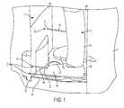
- the operator presence detector 20 comprises a first detector 25, a second detector 30, and a third detector 35.
- the first detector 25 is optional.
- the first detector 25 comprises multiple detectors arranged extending vertically above the threshold 55.
- Each of the first detector 25, the second detector 30, and the third detector 35 comprise an optical emitter and receiver where one of the emitter and receiver is located at a left side 40 and the other of the emitter and receiver is located at a right side 45 ( Fig.
- a retro-retlective type sensor may be used with a reflective material located proximate one of the sides 40 or 45 opposite the side 40 or 45 where a combined emitter and receiver is located. Ultrasonic, photoelectric (opposed, retroreflective, or proximity-sensing), acoustic, proximity, or radar, or other suitable detectors, may be used.
- the brake 50 may not be contigured to operate as part of the operator presence detector 20, but functions as a brake pedal that may be activated by the operator 15 to provide variable amounts of braking. In other words, brake 50 does not need to be configured as a dead-man switch.
- the brake is used in the logic sequence for initial start and static return to off (SRO) restart events to confirm brake switch function before vehicle functions are enabled.
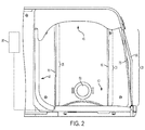
- the detectors 25, 30, and 35 preferably communicate with a processor located on the vehicle 5 (schematically illustrated as 95 in Fig. 2 ) that determines whether an object is detected by one or more of the detectors 25, 30, and 35 and controls one or more functions of vehicle 5.
- the detectors 25, 30, and 35 may be configured to generate an analogue or other suitable signal that is used to control one or more functions of vehicle 5 without a processor 95.
- one or more detectors 25 are positioned and configured to detect an object located above or that passes over the threshold 55, for example, an object intersecting the vertical, curved face extending above the threshold 55, of the operator compartment 10.
- Detector 30 is positioned above floor 90 and is configured to detect a left lower extremity, for example, foot 60, leg 62, or both, of operator 15.
- Detector 35 is positioned above floor 90 and is configured to detect a right lower extremity, for example, leg 65, foot 70, or both, of operator 15.
- detector 30 is positioned and configured to detect a left lower extremity (62 and 60) preferably at or above the toes and below the hip, and more preferably above the toes and below the ankle, of operator 15.
- detector 35 is positioned and configured to detect a right lower extremity (65 and 70) preferably at or above the toes and below the hip, and more preferably above the ankle and below the knee, of operator 15.
- the second detector 30 and the third detector 35 are positioned and arranged such that the operator 15 cannot cause both the second detector 30 and the third detector 35 to detect an object using one lower extremity, such as leg 65 and its connected foot 70, or leg 62 and its connected foot 60. In other words, the operator 15 must use one lower extremity to cause one of the second detector 30 and the third detector 35 to detect an object and the other lower extremity to cause the other of the second detector 30 and the third detector 35 to detect an object.
- the second detector 30 is located towards the rear of the operator compartment 10 and is proximate the threshold 55 of the operator compartment 10.
- the third detector 35 is located towards the front the operator compartment 10 and is proximate the front side 42 of the operator compartment 10 such that the second detector 30 and the third detector 35 are horizontally spaced apart ( Fig. 2 ), preferably no less than 150 millimeters (mm), and more preferably in a range of 275 mm to 285 mm. Other suitable distances may be used based on operator compartment contiguration, anticipated operator size, or other suitable factors affecting whether an operator is able to trigger a second detector, such as detector 30, and a third detector, such as detector 35, with a single lower extremity.
- the second detector 30 and the third detector 35 are illustrated as emitting a detection field from the left side 40 towards the right side 45 of the operator compartment 10, the direction in which a detection field is propagated is not important and one or both of the second detector 30 and the third detector 35 may emit in the reverse direction.
- a detection field is a volume within which a detector detects the presence of an object when at least a portion of an object is located within at least a portion of the volume.
- the volume occupied by the radiation beam comprises the detection field for a detector.
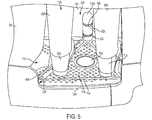
- radiation 75, 80 and 85 are conically shaped and have a cross-sectional area proximate the left side 40 of the operator compartment that is smaller than the cross-sectional area proximate the threshold 55.
- Other suitable detectors may have different detection fields.
- radiation is illustrated in Figs. 1 , 5 , and 6 as extending through a lower extremity to show the radiation path, however, in actuality such lower extremity blocks radiation and radiation only exists on one side of a lower extremity when a lower extremity is detected by a detector.
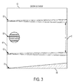
- the detection field from the second detector 30 diverges from the detection field of the third detector in a horizontal direction, a vertical direction, or both, as distance increases away from the left side 40.
- the horizontal distance between the boundary of the detection field associated with the second detector 30 that is closest to a boundary of the detection field associated with the third detector 35 may be 270 mm proximate the left side 40 and the horizontal distance between the boundary of the detection field associated with the second detector 30 that is closest to a boundary of the detection field associated with the third detector 35 may be 290 mm proximate the right side 45.
- the vertical distance between the boundary of the detection field associated with the second detector 30 that is closest to a boundary of the detection field associated with the third detector 35 may be 165 mm proximate the left side 40 and the vertical distance between the boundary of the detection field associated with the second detector 30 that is closest to a boundary of the detection field associated with the third detector 35 may be 155 mm proximate the right side 45.
- the detection field of the second detector 30 converges with respect to the detection field of the third detector 35 as distance increases away from the left side 40.
- the horizontal distance between the boundary of the detection field associated with the second detector 30 that is closest to a boundary of the detection field associated with the third detector 35 may be 290 mm proximate the left side 40 and the horizontal distance between the boundary of the detection field associated with the second detector 30 that is closest to a boundary of the detection field associated with the third detector 35 may be 270 mm proximate the right side 45.
- the vertical distance between the boundary of the detection field associated with the second detector 30 that is closest to a boundary of the detection field associated with the third detector 35 may be 145 mm proximate the left side 40 and the vertical distance between the boundary of the detection field associated with the second detector 30 that is closest to a boundary of the detection field associated with the third detector 35 may be 165 mm proximate the right side 45.
- the second detector 30 is located a distance above the floor 90 of the operator compartment 10 in a range of 10 mm to 800 mm, and preferably 25 mm to 35 mm.
- the third detector 35 is located a distance above the floor 90 of the operator compartment 10 in a range of 10 mm to 800 mm, and preferably 180 mm to 190 mm.
- the second detector 30 and the third detector 35 are vertically spaced apart in a range of 50 mm to 800 mm, and preferably of 145 mm to 165 mm.
- the detection field associated with the second detector 30 and the detection field associated with the third detector 35 may diverge or converge with respect to each other vertically as distance increases away from the left side 40.
- the detection field associated with the second detector 30 and the detection field associated with the third detector 35 may diverge or converge with respect to each other horizontally as distance increases away from the left side 40.
- the second detector 30 remains proximate the threshold 55 of the operator compartment 10, but is located above floor 90 in a range of 10 mm to 800 mm, and preferably 180 mm to 190 mm
- the third detector 35 remains proximate the front side 42 of the operator compartment 10, but is located above floor 90 in a range of 10 mm to 800 mm, and preferably 25 mm to 35 mm.
- the operator presence detector 20 is configured such that an operator 15 cannot cause both the second detector 30 and the third detector 35 to detect an object using one lower extremity. Because the target, an operator's left lower extremity (60 and 62) or right lower extremity (65 and 70), is relatively large, an operator may shift positions of either or both feet without deactivating the operator presence detector 20.
- an operator 15 is not necessarily required to maintain contact between one or both feet and the compartment floor 90 to trigger the second detector 30 or the third detector 35, unlike a conventional dead-man switch, and may obtain a changed position to relieve stress or fatigue or to become more comfortable without deactivating the operator presence detector 20.
- the second detector 30, the third detector 35, or both may comprise more than one detector, for example, 2, 3, or more detectors may be used to detect an operator's lower left extremity and 2, 3, or more detectors may be used to detect an operator's lower right extremity such that there is vertical spacing, horizontal spacing, or both, between each of the plurality of detectors comprising the second detector 30, the third detector 35, or both.
- the first detector 25 is located proximate to the threshold 55 of the operator compartment 10, and is preferably to the rear (horizontally) of the second detector 30, such that the second detector 30 is located between the first detector 25 and the third detector 35.
- the first detector 25 emits radiation 75, or other suitable signal or source, to detect an object that is above the threshold 55 and is preferably placed sufficiently close to the threshold 55 to detect any portion of an operator that intersects the vertical, curved face extending above the threshold 55.
- the first detector 25 is in a range of 15 mm to 35 mm above the floor 90, preferably in a range of 25 mm to 30 mm.
- the first detector 25 may comprise more than one detector, for example 2, 3, or more detectors may be located above the threshold 55 such that there is vertical spacing between each of the detectors and each of the detectors are arranged proximate the vertical, curved face extending above the threshold 55.
- the first detector 25 comprises multiple detectors where the detectors span between the floor 90 and a top of an operator compartment ( Fig. 2 ).
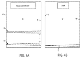
- an operator presence detector 20A contigured for an operator 15A using a fore/aft stance is illustrated.
- a portion of the second detector 30A is located near a front side 42A of the operator compartment 10A and a portion of the third detector 35A is also located near the front side 42A of the operator compartment 10A such that the second detector 30A and the third detector 35A have portions that are vertically aligned, in other words, stacked with one portion above the other, and are optionally vertically spaced apart in a range of 0 mm to 800 mm, and preferably of 10 mm to 50 mm.
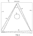
- an upper boundary of the detection field associated with the second detector 30A, such as radiation 80A, and a lower boundary of the detection field associated with the third detector 35A, such as radiation 85A, remain separated by a closest vertical distance V2 ( Fig. 9a ), that is in a range of 0 mm to 800 mm, and preferably 10 mm to 50 mm. In other embodiments, other distances may be used.
- the detection field, such as radiation 80A, or other suitable signal or source, associated with the second detector 30A, and the detection field, such as radiation 85A, or other suitable signal or source, associated with the third detector 35A, respectively, are vertically aligned with each other proximate the front side 42A and diverge from each other in a direction extending from the front side 42A toward the threshold 55A.
- the second detector 30A and the third detector 35A may be vertically aligned by including a portion of each detector in post 100A.
- An example of diverging detection fields is illustrated by radiation 80A originating from the second detector 30A located in post 100A and being received by an optical detector 81A located on the left side 40A of the operator compartment 10A while radiation 85A originates from third detector 35A located in post 100A and is directed to an optical detector 86A located on the right side 45A of the operator compartment 10A.
- a greater detection field divergence may be created by locating optical detectors 81A and 86A, or other suitable detector components, closer to the front side 42A of the operator compartment 10A.
- a lesser detection field divergence may be created by horizontally offsetting the portion of the second detector 30A and the portion of the third detector 35A on either side of the center of front side 42A, for example, by locating the portion of the second detector 30A closer to the left side 40A and by locating the portion of the third detector 35A closer to the right side 45A.
- second detector 30A and the third detector 35A portions may be horizontally spaced apart no less than 150 mm, and preferably in a range of 270 mm to 290 mm.
- the angle ⁇ ( Fig.
- the optical emitter for the second detector 30A and the optical receiver for the third detector 35A are located in post 100A, the optical receiver for the second detector 30A is located on the left side 40A and the emitter for the third detector 35A is located on the right side 45A.
- both emitters or both receivers may be located in the post 100A, or components of the second detector 30A and the third detector 35A may be located in or on the front side 42A.
- the second detector 30A is located a distance above the floor 90A of the operator compartment 10A in a range of 10 mm to 800 mm, and preferably 10 mm to 50 mm.
- the third detector 35A is located a distance above the floor 90A of the operator compartment 10A in a range of 10 mm to 800 mm, and preferably 20 mm to 100 mm.
- the second detector 30A and the third detector 35A may be located at the same, or approximately the same, vertical height above floor 90A, or the second detector 30A and the third detector 35A may be vertically spaced apart in a range of 0 mm to 800 mm, and preferably of 10 mm to 50 mm.
- the detection field associated with the second detector 30A and the third detector 35A may diverge or converge with respect to each other horizontally, vertically, or both, as distance increases away from the front side 42A.
- the operator presence detector 20A is configured such that an operator 15A cannot cause both the second detector 30A and the third detector 35A to detect an object using one lower extremity. Because the target, an operator's left lower extremity (60A and 62A) or right lower extremity (65A and 70A), is relatively large, an operator may shift positions of either or both feet without deactivating the operator presence detector 20A.
- an operator 15A may obtain a changed position to relieve stress or fatigue or to become more comfortable without deactivating an operator presence detector that comprises the second detector 30A and the third detector 35A.
- the second detector 30A, the third detector 35A, or both may comprise more than one detector, for example, 2, 3, or more detectors may be used to detect an operator's lower extremities such that there is vertical spacing, horizontal spacing, or both, between each of the plurality of detectors comprising the second detector 30A, the third detector 35A, or both.
- the first detector 25A is located over or proximate to the threshold 55A of the operator compartment 10A, and is preferably constructed as described with respect to the first detector 25 ( Fig. 1 ).
- the processor 95/95A may be programmed to disable one or more functions of vehicle 5/5A, such as traction.
- the processor 95/95A may be programmed to enable one or more functions of vehicle 5/5A.
- the processor 95/95A is programmed to enable one or more functions of vehicle 5/5A, but in a limited capacity. For example, traction may be enabled, but limited to 10% of the vehicle's top speed.
- the processor 95/95A may be programmed to disable one or more functions of vehicle 5/5A if the optional first detector 25/25A, when included, detects an object.
- the enabling, disabling, and limiting of vehicle functions correlating to states of object detection by the detectors 25/25A, 30/30A, and 35/35A may vary according to type of vehicle, vehicle operating environment, desired vehicle operation or other suitable factors.
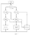
- An exemplary method of operating an industrial vehicle 5/5A comprises verifying whether detectors 25/25A, 30/30A, and 35/35A are functioning at step 1000, for example, using processor 95/95A at vehicle 5/5A start-up.
- step 1005 detecting whether an operator's left lower extremity (60/60A and 62/62A), or a portion thereof such as foot 60/60A, is present when the detected left lower extremity (60/60A and 62/62A) is located in the operator compartment 10/10A.
- the method also comprises, at step 1010, detecting whether an operator's right lower extremity (65/65A and 70/70A), or a portion thereof such as leg 65/65A, is present when the right lower extremity (65/65A and 70/70A) is also located in the operator compartment 10/10A.
- the method also comprises detecting whether an object is located over a threshold, such as threshold 55/55A, to the operator compartment 10/10A at step 1015.
- the method comprises enabling a vehicle function, such as traction, if (a) an operator left lower extremity (60/60A and 62/62A) is detected at step 1005, (b) an operator right lower extremity (65/65A and 70/70A) is detected at step 1010, and (c) no object located over the threshold 55/55A to the operator compartment 10/10A is detected at step 1015.
- a vehicle function such as traction
- the exemplary method also includes disabling the vehicle function at step 1040 if an object located over the threshold 55/55A to the operator compartment 10/10A is detected at step 1015.
- the method includes limiting operation of the vehicle function at step 1035 if (a) an operator left lower extremity (60/60A and 62/62A) is not detected at step 1005, (b) an operator right lower extremity (65/65A and 70/70A) is detected at step 1025, and (c) no object located over the threshold 55/55A to the operator compartment 10/10A is detected at step 1030; or if (d) an operator left lower extremity (60/60A and 62/62A) is detected at step 1005, (e) an operator right lower extremity (65/65A and 70/70A) is not detected at step 1010, and (f) no object located over the threshold 55/55A to the operator compartment 10/10A is detected at step 1030.
- the vehicle function may be disabled instead of limited at step 1035.
- the method also includes disabling operation of the vehicle function at step 1040 if (a) an operator left lower extremity (60/60A and 62/62A) is not detected at step 1005, and (b) an operator right lower extremity (65/65A and 70/70A) is not detected at step 1025, even if no object located over the threshold 55/55A to the operator compartment 10/10A is detected; or if an object is detected at step 1030.
- Another exemplary method of operating an industrial vehicle 5/5A comprises verifying whether detectors 25/25A, 30/30A, and 35/35A are functioning at step 1000, for example, using processor 95/95A at vehicle 5/5A start-up.
- step 1005 detecting that an operator's left lower extremity (60/60A and 62/62A), or a portion thereof such as foot 60/60A, is present when the detected left lower extremity (60/60A and 62/62A) is located in the operator compartment 10/10A.
- the method also comprises, at step 1010, detecting that an operator's right lower extremity (65/65A and 70/70A), or a portion thereof such as leg 65/65A, is present when the right lower extremity (65/65A and 70/70A) is also located in the operator compartment 10/10A, and skips directly to enabling a vehicle function, such as traction, at step 1020, without detecting whether an object is located over the threshold 55/55A to the operator compartment 10/10A at step 1015.
- a vehicle function such as traction
- the other exemplary method also includes limiting operation of the vehicle function at step 1035 if (a) an operator left lower extremity (60/60A and 62/62A) is not detected at step 1005, and (b) an operator right lower extremity (65/65A and 70/70A) is detected at step 1025, and (c) omitting step 1030; or if (d) an operator left lower extremity (60/60A and 62/62A) is detected at step 1005, (e) an operator right lower extremity (65/65A and 70/70A) is not detected at step 1010, and (f) omitting step 1030.
- another embodiment may disable the vehicle function at step 1035 if (a) an operator left lower extremity (60/60A and 62/62A) is not detected at step 1005, and (b) an operator right lower extremity (65/65A and 70/70A) is detected at step 1025, and (c) omitting step 1030; or if (d) an operator left lower extremity (60/60A and 62/62A) is detected at step 1005, (e) an operator right lower extremity (65/65A and 70/70A) is not detected at step 1010, and (f) omitting step 1030.
- the other exemplary method also includes disabling the vehicle function at step 1040 if (a) an operator left lower extremity (60/60A and 62/62A) is not detected at step 1005, and (b) an operator right lower extremity (65/65A and 70/70A) is not detected at step 1025.
Landscapes
- Engineering & Computer Science (AREA)
- Mechanical Engineering (AREA)
- Transportation (AREA)
- Structural Engineering (AREA)
- Life Sciences & Earth Sciences (AREA)
- Geology (AREA)
- Civil Engineering (AREA)
- Chemical & Material Sciences (AREA)
- Combustion & Propulsion (AREA)
- Physics & Mathematics (AREA)
- Automation & Control Theory (AREA)
- Mathematical Physics (AREA)
- Forklifts And Lifting Vehicles (AREA)
- Geophysics And Detection Of Objects (AREA)
Priority Applications (1)
| Application Number | Priority Date | Filing Date | Title |
|---|---|---|---|
| EP19214129.9A EP3647105B1 (fr) | 2015-01-27 | 2016-01-26 | Système de présence d'opérateur |
Applications Claiming Priority (1)
| Application Number | Priority Date | Filing Date | Title |
|---|---|---|---|
| US201562108394P | 2015-01-27 | 2015-01-27 |
Related Child Applications (2)
| Application Number | Title | Priority Date | Filing Date |
|---|---|---|---|
| EP19214129.9A Division EP3647105B1 (fr) | 2015-01-27 | 2016-01-26 | Système de présence d'opérateur |
| EP19214129.9A Division-Into EP3647105B1 (fr) | 2015-01-27 | 2016-01-26 | Système de présence d'opérateur |
Publications (2)
| Publication Number | Publication Date |
|---|---|
| EP3050737A1 true EP3050737A1 (fr) | 2016-08-03 |
| EP3050737B1 EP3050737B1 (fr) | 2020-03-25 |
Family
ID=55274980
Family Applications (2)
| Application Number | Title | Priority Date | Filing Date |
|---|---|---|---|
| EP19214129.9A Active EP3647105B1 (fr) | 2015-01-27 | 2016-01-26 | Système de présence d'opérateur |
| EP16152695.9A Active EP3050737B1 (fr) | 2015-01-27 | 2016-01-26 | Système de présence d'opérateur |
Family Applications Before (1)
| Application Number | Title | Priority Date | Filing Date |
|---|---|---|---|
| EP19214129.9A Active EP3647105B1 (fr) | 2015-01-27 | 2016-01-26 | Système de présence d'opérateur |
Country Status (3)
| Country | Link |
|---|---|
| US (1) | US10023142B2 (fr) |
| EP (2) | EP3647105B1 (fr) |
| CN (2) | CN111572550B (fr) |
Families Citing this family (8)
| Publication number | Priority date | Publication date | Assignee | Title |
|---|---|---|---|---|
| DE102015111178A1 (de) * | 2015-07-10 | 2017-01-12 | Jungheinrich Aktiengesellschaft | Standplattform für ein Flurförderzeug |
| JP6214017B1 (ja) | 2016-11-09 | 2017-10-18 | ニチユ三菱フォークリフト株式会社 | 立ち乗り式の荷役車両 |
| US11427450B2 (en) | 2018-06-01 | 2022-08-30 | Hyster-Yale Group, Inc. | Lift truck having advantageous design elements |
| US11104318B2 (en) | 2018-12-10 | 2021-08-31 | Bendix Commercial Vehicle Systems Llc | Parking brake apparatus for a vehicle |
| US11110906B2 (en) | 2018-12-10 | 2021-09-07 | Bendix Commercial Vehicle Systems Llc | Parking brake apparatus for a vehicle |
| CA3163133C (fr) | 2020-02-21 | 2025-05-27 | Crown Equipment Corporation | Système d'aide au positionnement pour un véhicule de manutention de matériaux |
| DE102022131242B4 (de) | 2022-11-25 | 2025-11-27 | Sick Ag | System mit einem Sensor und zugehöriges Verfahren |
| DE202022106600U1 (de) | 2022-11-25 | 2024-02-28 | Sick Ag | System mit einem Sensor |
Citations (3)
| Publication number | Priority date | Publication date | Assignee | Title |
|---|---|---|---|---|
| US4840248A (en) * | 1987-06-02 | 1989-06-20 | Silverman Edward J | Safety switch light fence |
| US20050270147A1 (en) * | 2004-06-02 | 2005-12-08 | Lewis Robert J | Photoelectric operator position detector |
| US20070074923A1 (en) * | 2004-09-23 | 2007-04-05 | Crown Equipment Corporation | Rotating and/or swiveling seat |
Family Cites Families (9)
| Publication number | Priority date | Publication date | Assignee | Title |
|---|---|---|---|---|
| US6241047B1 (en) * | 1995-10-05 | 2001-06-05 | Crown Equipment Corporation | Personnel carrying vehicle |
| US5835008A (en) | 1995-11-28 | 1998-11-10 | Colemere, Jr.; Dale M. | Driver, vehicle and traffic information system |
| KR20010020483A (ko) | 1997-07-16 | 2001-03-15 | 크라운 이큅먼트 코포레이션 | 물질 취급 차량용 장치 |
| US6974948B1 (en) * | 2000-05-26 | 2005-12-13 | Brent Mark R | Perimetric detection system |
| WO2006110648A2 (fr) * | 2005-04-08 | 2006-10-19 | Nmhg Oregon, Llc | Systeme de pedale et de tapis de sol pour vehicule industriel |
| US7899597B2 (en) * | 2006-02-24 | 2011-03-01 | Caterpillar Inc. | Work machine with operator presence detection strategy |
| US8485301B2 (en) | 2010-06-15 | 2013-07-16 | Shem, Llc | Operator monitoring system for a vehicle |
| EP2407705B1 (fr) * | 2010-07-13 | 2013-09-11 | Joseph Vögele AG | Engin doté d'un système de détection de présence |
| US8924039B2 (en) | 2012-06-29 | 2014-12-30 | Nacco Materials Handling Group, Inc. | Vehicle operator presence detector |
-
2016
- 2016-01-22 US US15/004,758 patent/US10023142B2/en active Active
- 2016-01-26 EP EP19214129.9A patent/EP3647105B1/fr active Active
- 2016-01-26 EP EP16152695.9A patent/EP3050737B1/fr active Active
- 2016-01-27 CN CN202010558335.0A patent/CN111572550B/zh active Active
- 2016-01-27 CN CN201610206103.2A patent/CN105857074B/zh active Active
Patent Citations (3)
| Publication number | Priority date | Publication date | Assignee | Title |
|---|---|---|---|---|
| US4840248A (en) * | 1987-06-02 | 1989-06-20 | Silverman Edward J | Safety switch light fence |
| US20050270147A1 (en) * | 2004-06-02 | 2005-12-08 | Lewis Robert J | Photoelectric operator position detector |
| US20070074923A1 (en) * | 2004-09-23 | 2007-04-05 | Crown Equipment Corporation | Rotating and/or swiveling seat |
Also Published As
| Publication number | Publication date |
|---|---|
| CN105857074B (zh) | 2020-07-14 |
| CN111572550B (zh) | 2023-06-06 |
| US10023142B2 (en) | 2018-07-17 |
| US20160214556A1 (en) | 2016-07-28 |
| EP3647105A1 (fr) | 2020-05-06 |
| CN111572550A (zh) | 2020-08-25 |
| EP3050737B1 (fr) | 2020-03-25 |
| EP3647105B1 (fr) | 2021-03-31 |
| CN105857074A (zh) | 2016-08-17 |
Similar Documents
| Publication | Publication Date | Title |
|---|---|---|
| EP3647105B1 (fr) | Système de présence d'opérateur | |
| CN105386393B (zh) | 自动铣刨机以及用于排放铣刨材料的方法 | |
| US8924039B2 (en) | Vehicle operator presence detector | |
| JP7370189B2 (ja) | 作業機械及び作業機械の制御方法 | |
| US11027953B2 (en) | Method for monitoring the road path of a truck and a floor conveyor | |
| US10793408B2 (en) | Stand-up riding type cargo handling vehicle | |
| KR102824919B1 (ko) | 작업 차량 | |
| EP3298877A1 (fr) | Véhicule de récolte pour la récolte de cultures par un utilisateur, en particulier des asperges vertes | |
| JP2019064539A (ja) | 状態検出装置、状態検出システム及び状態検出プログラム | |
| US9561944B2 (en) | Reverse drive handle for lift truck | |
| JP2015154608A (ja) | 移動体及びその最高速度の制御方法 | |
| US20220050209A1 (en) | Work Machine | |
| KR20210057652A (ko) | 차량 제어 시스템, 차량 제어 시스템을 포함하는 차량, 및 차량 제어 방법 | |
| CN108431825A (zh) | 用于检测机动车辆驾驶员下肢位置的方法和装置 | |
| WO2018084147A1 (fr) | Procédé de détection d'occupant et appareil de détection d'occupant | |
| JP5873909B1 (ja) | 荷役車両 | |
| US20140049029A1 (en) | Steering column for a work vehicle with integral adjustable foot rests | |
| US10414290B2 (en) | Occupant support for a vehicle | |
| US12517247B2 (en) | System having a sensor and associated method | |
| KR20130060511A (ko) | 차량 시트 제어 장치 및 차량 기울어짐 제어 시스템 | |
| JPWO2024004195A5 (fr) | ||
| US10059243B2 (en) | Motor vehicle having a sloping footrest | |
| JP2017014988A (ja) | 作業機 | |
| WO2018084148A1 (fr) | Procédé de détection d'occupant et appareil de détection d'occupant | |
| JP2003061450A (ja) | コンバインにおける警報装置 |
Legal Events
| Date | Code | Title | Description |
|---|---|---|---|
| PUAI | Public reference made under article 153(3) epc to a published international application that has entered the european phase |
Free format text: ORIGINAL CODE: 0009012 |
|
| AK | Designated contracting states |
Kind code of ref document: A1 Designated state(s): AL AT BE BG CH CY CZ DE DK EE ES FI FR GB GR HR HU IE IS IT LI LT LU LV MC MK MT NL NO PL PT RO RS SE SI SK SM TR |
|
| AX | Request for extension of the european patent |
Extension state: BA ME |
|
| STAA | Information on the status of an ep patent application or granted ep patent |
Free format text: STATUS: REQUEST FOR EXAMINATION WAS MADE |
|
| 17P | Request for examination filed |
Effective date: 20170126 |
|
| RBV | Designated contracting states (corrected) |
Designated state(s): AL AT BE BG CH CY CZ DE DK EE ES FI FR GB GR HR HU IE IS IT LI LT LU LV MC MK MT NL NO PL PT RO RS SE SI SK SM TR |
|
| STAA | Information on the status of an ep patent application or granted ep patent |
Free format text: STATUS: EXAMINATION IS IN PROGRESS |
|
| 17Q | First examination report despatched |
Effective date: 20181005 |
|
| GRAP | Despatch of communication of intention to grant a patent |
Free format text: ORIGINAL CODE: EPIDOSNIGR1 |
|
| STAA | Information on the status of an ep patent application or granted ep patent |
Free format text: STATUS: GRANT OF PATENT IS INTENDED |
|
| INTG | Intention to grant announced |
Effective date: 20190621 |
|
| RIN1 | Information on inventor provided before grant (corrected) |
Inventor name: WAVREK, MATTHEW Inventor name: MCGOLDRICK, KEVIN Inventor name: GOODWIN, CHROSTOPHER J. Inventor name: ADCOX, ROBERT STEPHEN Inventor name: JAMES, WILLIAM EUGENE Inventor name: SCHREIBER, KEN |
|
| GRAS | Grant fee paid |
Free format text: ORIGINAL CODE: EPIDOSNIGR3 |
|
| GRAJ | Information related to disapproval of communication of intention to grant by the applicant or resumption of examination proceedings by the epo deleted |
Free format text: ORIGINAL CODE: EPIDOSDIGR1 |
|
| GRAL | Information related to payment of fee for publishing/printing deleted |
Free format text: ORIGINAL CODE: EPIDOSDIGR3 |
|
| STAA | Information on the status of an ep patent application or granted ep patent |
Free format text: STATUS: EXAMINATION IS IN PROGRESS |
|
| GRAJ | Information related to disapproval of communication of intention to grant by the applicant or resumption of examination proceedings by the epo deleted |
Free format text: ORIGINAL CODE: EPIDOSDIGR1 |
|
| STAA | Information on the status of an ep patent application or granted ep patent |
Free format text: STATUS: GRANT OF PATENT IS INTENDED |
|
| GRAP | Despatch of communication of intention to grant a patent |
Free format text: ORIGINAL CODE: EPIDOSNIGR1 |
|
| INTC | Intention to grant announced (deleted) | ||
| INTG | Intention to grant announced |
Effective date: 20191125 |
|
| GRAA | (expected) grant |
Free format text: ORIGINAL CODE: 0009210 |
|
| STAA | Information on the status of an ep patent application or granted ep patent |
Free format text: STATUS: THE PATENT HAS BEEN GRANTED |
|
| AK | Designated contracting states |
Kind code of ref document: B1 Designated state(s): AL AT BE BG CH CY CZ DE DK EE ES FI FR GB GR HR HU IE IS IT LI LT LU LV MC MK MT NL NO PL PT RO RS SE SI SK SM TR |
|
| REG | Reference to a national code |
Ref country code: GB Ref legal event code: FG4D |
|
| REG | Reference to a national code |
Ref country code: AT Ref legal event code: REF Ref document number: 1248183 Country of ref document: AT Kind code of ref document: T Effective date: 20200415 Ref country code: IE Ref legal event code: FG4D |
|
| REG | Reference to a national code |
Ref country code: DE Ref legal event code: R096 Ref document number: 602016032358 Country of ref document: DE |
|
| PG25 | Lapsed in a contracting state [announced via postgrant information from national office to epo] |
Ref country code: NO Free format text: LAPSE BECAUSE OF FAILURE TO SUBMIT A TRANSLATION OF THE DESCRIPTION OR TO PAY THE FEE WITHIN THE PRESCRIBED TIME-LIMIT Effective date: 20200625 Ref country code: RS Free format text: LAPSE BECAUSE OF FAILURE TO SUBMIT A TRANSLATION OF THE DESCRIPTION OR TO PAY THE FEE WITHIN THE PRESCRIBED TIME-LIMIT Effective date: 20200325 Ref country code: FI Free format text: LAPSE BECAUSE OF FAILURE TO SUBMIT A TRANSLATION OF THE DESCRIPTION OR TO PAY THE FEE WITHIN THE PRESCRIBED TIME-LIMIT Effective date: 20200325 |
|
| PG25 | Lapsed in a contracting state [announced via postgrant information from national office to epo] |
Ref country code: LV Free format text: LAPSE BECAUSE OF FAILURE TO SUBMIT A TRANSLATION OF THE DESCRIPTION OR TO PAY THE FEE WITHIN THE PRESCRIBED TIME-LIMIT Effective date: 20200325 Ref country code: GR Free format text: LAPSE BECAUSE OF FAILURE TO SUBMIT A TRANSLATION OF THE DESCRIPTION OR TO PAY THE FEE WITHIN THE PRESCRIBED TIME-LIMIT Effective date: 20200626 Ref country code: SE Free format text: LAPSE BECAUSE OF FAILURE TO SUBMIT A TRANSLATION OF THE DESCRIPTION OR TO PAY THE FEE WITHIN THE PRESCRIBED TIME-LIMIT Effective date: 20200325 Ref country code: HR Free format text: LAPSE BECAUSE OF FAILURE TO SUBMIT A TRANSLATION OF THE DESCRIPTION OR TO PAY THE FEE WITHIN THE PRESCRIBED TIME-LIMIT Effective date: 20200325 Ref country code: BG Free format text: LAPSE BECAUSE OF FAILURE TO SUBMIT A TRANSLATION OF THE DESCRIPTION OR TO PAY THE FEE WITHIN THE PRESCRIBED TIME-LIMIT Effective date: 20200625 |
|
| REG | Reference to a national code |
Ref country code: NL Ref legal event code: MP Effective date: 20200325 |
|
| REG | Reference to a national code |
Ref country code: LT Ref legal event code: MG4D |
|
| PG25 | Lapsed in a contracting state [announced via postgrant information from national office to epo] |
Ref country code: NL Free format text: LAPSE BECAUSE OF FAILURE TO SUBMIT A TRANSLATION OF THE DESCRIPTION OR TO PAY THE FEE WITHIN THE PRESCRIBED TIME-LIMIT Effective date: 20200325 |
|
| PG25 | Lapsed in a contracting state [announced via postgrant information from national office to epo] |
Ref country code: PT Free format text: LAPSE BECAUSE OF FAILURE TO SUBMIT A TRANSLATION OF THE DESCRIPTION OR TO PAY THE FEE WITHIN THE PRESCRIBED TIME-LIMIT Effective date: 20200818 Ref country code: SK Free format text: LAPSE BECAUSE OF FAILURE TO SUBMIT A TRANSLATION OF THE DESCRIPTION OR TO PAY THE FEE WITHIN THE PRESCRIBED TIME-LIMIT Effective date: 20200325 Ref country code: IS Free format text: LAPSE BECAUSE OF FAILURE TO SUBMIT A TRANSLATION OF THE DESCRIPTION OR TO PAY THE FEE WITHIN THE PRESCRIBED TIME-LIMIT Effective date: 20200725 Ref country code: RO Free format text: LAPSE BECAUSE OF FAILURE TO SUBMIT A TRANSLATION OF THE DESCRIPTION OR TO PAY THE FEE WITHIN THE PRESCRIBED TIME-LIMIT Effective date: 20200325 Ref country code: CZ Free format text: LAPSE BECAUSE OF FAILURE TO SUBMIT A TRANSLATION OF THE DESCRIPTION OR TO PAY THE FEE WITHIN THE PRESCRIBED TIME-LIMIT Effective date: 20200325 Ref country code: SM Free format text: LAPSE BECAUSE OF FAILURE TO SUBMIT A TRANSLATION OF THE DESCRIPTION OR TO PAY THE FEE WITHIN THE PRESCRIBED TIME-LIMIT Effective date: 20200325 Ref country code: EE Free format text: LAPSE BECAUSE OF FAILURE TO SUBMIT A TRANSLATION OF THE DESCRIPTION OR TO PAY THE FEE WITHIN THE PRESCRIBED TIME-LIMIT Effective date: 20200325 Ref country code: LT Free format text: LAPSE BECAUSE OF FAILURE TO SUBMIT A TRANSLATION OF THE DESCRIPTION OR TO PAY THE FEE WITHIN THE PRESCRIBED TIME-LIMIT Effective date: 20200325 |
|
| REG | Reference to a national code |
Ref country code: AT Ref legal event code: MK05 Ref document number: 1248183 Country of ref document: AT Kind code of ref document: T Effective date: 20200325 |
|
| REG | Reference to a national code |
Ref country code: DE Ref legal event code: R097 Ref document number: 602016032358 Country of ref document: DE |
|
| PG25 | Lapsed in a contracting state [announced via postgrant information from national office to epo] |
Ref country code: ES Free format text: LAPSE BECAUSE OF FAILURE TO SUBMIT A TRANSLATION OF THE DESCRIPTION OR TO PAY THE FEE WITHIN THE PRESCRIBED TIME-LIMIT Effective date: 20200325 Ref country code: DK Free format text: LAPSE BECAUSE OF FAILURE TO SUBMIT A TRANSLATION OF THE DESCRIPTION OR TO PAY THE FEE WITHIN THE PRESCRIBED TIME-LIMIT Effective date: 20200325 Ref country code: AT Free format text: LAPSE BECAUSE OF FAILURE TO SUBMIT A TRANSLATION OF THE DESCRIPTION OR TO PAY THE FEE WITHIN THE PRESCRIBED TIME-LIMIT Effective date: 20200325 |
|
| PLBE | No opposition filed within time limit |
Free format text: ORIGINAL CODE: 0009261 |
|
| STAA | Information on the status of an ep patent application or granted ep patent |
Free format text: STATUS: NO OPPOSITION FILED WITHIN TIME LIMIT |
|
| PG25 | Lapsed in a contracting state [announced via postgrant information from national office to epo] |
Ref country code: PL Free format text: LAPSE BECAUSE OF FAILURE TO SUBMIT A TRANSLATION OF THE DESCRIPTION OR TO PAY THE FEE WITHIN THE PRESCRIBED TIME-LIMIT Effective date: 20200325 |
|
| 26N | No opposition filed |
Effective date: 20210112 |
|
| PG25 | Lapsed in a contracting state [announced via postgrant information from national office to epo] |
Ref country code: SI Free format text: LAPSE BECAUSE OF FAILURE TO SUBMIT A TRANSLATION OF THE DESCRIPTION OR TO PAY THE FEE WITHIN THE PRESCRIBED TIME-LIMIT Effective date: 20200325 |
|
| PG25 | Lapsed in a contracting state [announced via postgrant information from national office to epo] |
Ref country code: MC Free format text: LAPSE BECAUSE OF FAILURE TO SUBMIT A TRANSLATION OF THE DESCRIPTION OR TO PAY THE FEE WITHIN THE PRESCRIBED TIME-LIMIT Effective date: 20200325 |
|
| REG | Reference to a national code |
Ref country code: CH Ref legal event code: PL |
|
| PG25 | Lapsed in a contracting state [announced via postgrant information from national office to epo] |
Ref country code: LU Free format text: LAPSE BECAUSE OF NON-PAYMENT OF DUE FEES Effective date: 20210126 |
|
| REG | Reference to a national code |
Ref country code: BE Ref legal event code: MM Effective date: 20210131 |
|
| PG25 | Lapsed in a contracting state [announced via postgrant information from national office to epo] |
Ref country code: LI Free format text: LAPSE BECAUSE OF NON-PAYMENT OF DUE FEES Effective date: 20210131 Ref country code: CH Free format text: LAPSE BECAUSE OF NON-PAYMENT OF DUE FEES Effective date: 20210131 |
|
| PG25 | Lapsed in a contracting state [announced via postgrant information from national office to epo] |
Ref country code: IE Free format text: LAPSE BECAUSE OF NON-PAYMENT OF DUE FEES Effective date: 20210126 |
|
| PG25 | Lapsed in a contracting state [announced via postgrant information from national office to epo] |
Ref country code: BE Free format text: LAPSE BECAUSE OF NON-PAYMENT OF DUE FEES Effective date: 20210131 |
|
| PG25 | Lapsed in a contracting state [announced via postgrant information from national office to epo] |
Ref country code: HU Free format text: LAPSE BECAUSE OF FAILURE TO SUBMIT A TRANSLATION OF THE DESCRIPTION OR TO PAY THE FEE WITHIN THE PRESCRIBED TIME-LIMIT; INVALID AB INITIO Effective date: 20160126 |
|
| PG25 | Lapsed in a contracting state [announced via postgrant information from national office to epo] |
Ref country code: CY Free format text: LAPSE BECAUSE OF FAILURE TO SUBMIT A TRANSLATION OF THE DESCRIPTION OR TO PAY THE FEE WITHIN THE PRESCRIBED TIME-LIMIT Effective date: 20200325 |
|
| P01 | Opt-out of the competence of the unified patent court (upc) registered |
Effective date: 20230530 |
|
| PG25 | Lapsed in a contracting state [announced via postgrant information from national office to epo] |
Ref country code: MK Free format text: LAPSE BECAUSE OF FAILURE TO SUBMIT A TRANSLATION OF THE DESCRIPTION OR TO PAY THE FEE WITHIN THE PRESCRIBED TIME-LIMIT Effective date: 20200325 |
|
| PG25 | Lapsed in a contracting state [announced via postgrant information from national office to epo] |
Ref country code: TR Free format text: LAPSE BECAUSE OF FAILURE TO SUBMIT A TRANSLATION OF THE DESCRIPTION OR TO PAY THE FEE WITHIN THE PRESCRIBED TIME-LIMIT Effective date: 20200325 |
|
| REG | Reference to a national code |
Ref country code: DE Ref legal event code: R081 Ref document number: 602016032358 Country of ref document: DE Owner name: HYSTER-YALE MATERIALS HANDLING, INC. (N.D.GES., US Free format text: FORMER OWNER: HYSTER-YALE GROUP, INC., FAIRVIEW, OREG., US |
|
| PG25 | Lapsed in a contracting state [announced via postgrant information from national office to epo] |
Ref country code: MT Free format text: LAPSE BECAUSE OF FAILURE TO SUBMIT A TRANSLATION OF THE DESCRIPTION OR TO PAY THE FEE WITHIN THE PRESCRIBED TIME-LIMIT Effective date: 20200325 |
|
| PGFP | Annual fee paid to national office [announced via postgrant information from national office to epo] |
Ref country code: GB Payment date: 20251210 Year of fee payment: 11 |
|
| PGFP | Annual fee paid to national office [announced via postgrant information from national office to epo] |
Ref country code: FR Payment date: 20251210 Year of fee payment: 11 |
|
| PGFP | Annual fee paid to national office [announced via postgrant information from national office to epo] |
Ref country code: DE Payment date: 20251209 Year of fee payment: 11 |
|
| PGFP | Annual fee paid to national office [announced via postgrant information from national office to epo] |
Ref country code: IT Payment date: 20251201 Year of fee payment: 11 |