EP3049676B2 - Vakuumpumpe - Google Patents
Vakuumpumpe Download PDFInfo
- Publication number
- EP3049676B2 EP3049676B2 EP14761870.6A EP14761870A EP3049676B2 EP 3049676 B2 EP3049676 B2 EP 3049676B2 EP 14761870 A EP14761870 A EP 14761870A EP 3049676 B2 EP3049676 B2 EP 3049676B2
- Authority
- EP
- European Patent Office
- Prior art keywords
- housing portion
- heat
- vacuum pump
- housing
- stator
- Prior art date
- Legal status (The legal status is an assumption and is not a legal conclusion. Google has not performed a legal analysis and makes no representation as to the accuracy of the status listed.)
- Active
Links
Images
Classifications
-
- F—MECHANICAL ENGINEERING; LIGHTING; HEATING; WEAPONS; BLASTING
- F04—POSITIVE - DISPLACEMENT MACHINES FOR LIQUIDS; PUMPS FOR LIQUIDS OR ELASTIC FLUIDS
- F04D—NON-POSITIVE-DISPLACEMENT PUMPS
- F04D19/00—Axial-flow pumps
- F04D19/02—Multi-stage pumps
- F04D19/04—Multi-stage pumps specially adapted to the production of a high vacuum, e.g. molecular pumps
- F04D19/042—Turbomolecular vacuum pumps
-
- F—MECHANICAL ENGINEERING; LIGHTING; HEATING; WEAPONS; BLASTING
- F04—POSITIVE - DISPLACEMENT MACHINES FOR LIQUIDS; PUMPS FOR LIQUIDS OR ELASTIC FLUIDS
- F04D—NON-POSITIVE-DISPLACEMENT PUMPS
- F04D25/00—Pumping installations or systems
- F04D25/02—Units comprising pumps and their driving means
- F04D25/06—Units comprising pumps and their driving means the pump being electrically driven
-
- F—MECHANICAL ENGINEERING; LIGHTING; HEATING; WEAPONS; BLASTING
- F04—POSITIVE - DISPLACEMENT MACHINES FOR LIQUIDS; PUMPS FOR LIQUIDS OR ELASTIC FLUIDS
- F04D—NON-POSITIVE-DISPLACEMENT PUMPS
- F04D29/00—Details, component parts, or accessories
- F04D29/05—Shafts or bearings, or assemblies thereof, specially adapted for elastic fluid pumps
- F04D29/056—Bearings
-
- F—MECHANICAL ENGINEERING; LIGHTING; HEATING; WEAPONS; BLASTING
- F04—POSITIVE - DISPLACEMENT MACHINES FOR LIQUIDS; PUMPS FOR LIQUIDS OR ELASTIC FLUIDS
- F04D—NON-POSITIVE-DISPLACEMENT PUMPS
- F04D29/00—Details, component parts, or accessories
- F04D29/40—Casings; Connections of working fluid
- F04D29/52—Casings; Connections of working fluid for axial pumps
- F04D29/522—Casings; Connections of working fluid for axial pumps especially adapted for elastic fluid pumps
-
- F—MECHANICAL ENGINEERING; LIGHTING; HEATING; WEAPONS; BLASTING
- F04—POSITIVE - DISPLACEMENT MACHINES FOR LIQUIDS; PUMPS FOR LIQUIDS OR ELASTIC FLUIDS
- F04D—NON-POSITIVE-DISPLACEMENT PUMPS
- F04D29/00—Details, component parts, or accessories
- F04D29/58—Cooling; Heating; Diminishing heat transfer
- F04D29/5806—Cooling the drive system
-
- F—MECHANICAL ENGINEERING; LIGHTING; HEATING; WEAPONS; BLASTING
- F04—POSITIVE - DISPLACEMENT MACHINES FOR LIQUIDS; PUMPS FOR LIQUIDS OR ELASTIC FLUIDS
- F04D—NON-POSITIVE-DISPLACEMENT PUMPS
- F04D29/00—Details, component parts, or accessories
- F04D29/58—Cooling; Heating; Diminishing heat transfer
- F04D29/582—Cooling; Heating; Diminishing heat transfer specially adapted for elastic fluid pumps
- F04D29/584—Cooling; Heating; Diminishing heat transfer specially adapted for elastic fluid pumps cooling or heating the machine
-
- F—MECHANICAL ENGINEERING; LIGHTING; HEATING; WEAPONS; BLASTING
- F04—POSITIVE - DISPLACEMENT MACHINES FOR LIQUIDS; PUMPS FOR LIQUIDS OR ELASTIC FLUIDS
- F04D—NON-POSITIVE-DISPLACEMENT PUMPS
- F04D29/00—Details, component parts, or accessories
- F04D29/58—Cooling; Heating; Diminishing heat transfer
- F04D29/582—Cooling; Heating; Diminishing heat transfer specially adapted for elastic fluid pumps
- F04D29/5853—Cooling; Heating; Diminishing heat transfer specially adapted for elastic fluid pumps heat insulation or conduction
Definitions
- the invention relates to a vacuum pump, in particular a turbomolecular pump.
- Vacuum pumps have a rotor shaft that is usually connected to several rotor elements.
- the rotor elements in a turbomolecular pump for example, are several rotor disks that run essentially radially to the rotor shaft. Between the rotor disks, there are usually stator disks that are connected to the housing or arranged in the housing, which thus comprise several individual stator devices. The individual stator disks are thus arranged between adjacent rotor disks.
- a rotor element can also be, for example, rotating components of a Holweck stage, a Siegbahn stage or a Gaede stage, or a rotor of a side channel compressor. In particular, high temperatures occur in such types of pumps due to compression.
- the rotor shaft of the vacuum pump is also connected to a drive device such as an electric motor. Such components also often generate high temperatures. It is therefore necessary that such components that generate a lot of heat are cooled.
- the rotor shaft is supported by bearings.
- rolling bearings in particular are sensitive to temperature. At high operating temperatures, the service life of the rolling bearings decreases.
- the bearings, especially the bearing on the pressure side, are often located in a small space and therefore close to the electric drive unit and the area in which high gas compression and thus high heat loss is generated. This means that the bearings are operated at high operating temperatures.
- the publication WO 94/00694 A1 describes a gas friction vacuum pump with a high vacuum and a pre-vacuum range that operate at different operating temperatures.
- the publication DE 39 32 228 A1 describes a turbo vacuum pump with a circumferential flow impeller and a one-piece stator.
- the object of the invention is to reduce the operating temperature of bearings, in particular rolling bearings, in vacuum pumps using structurally simple means.
- a vacuum pump has a rotor shaft and at least one rotor element. Furthermore, at least one stator device is provided which interacts with the at least one rotor element. Furthermore, an electric drive device and bearings supporting the rotor shaft are connected to the rotor shaft. Furthermore, the vacuum pump has a housing in which the components of the pump are arranged. In particular, the housing supports the rotor shaft via the bearings. Furthermore, the at least one stator device is connected directly or indirectly to the housing. According to the invention, the housing has several housing parts, with heat-sensitive components being connected to a first housing part and components which generate a lot of heat being connected to a second housing part.
- the high heat generated for example, in the compressor part and/or by the drive device to be dissipated, so that the operating temperature of heat-sensitive components can be reduced, with the heat-sensitive component being one of the bearings.
- the high heat generated within the pump is thus introduced into the bearing as little as possible.
- the second housing part is connected to the drive device in a thermally conductive manner. This allows the heat generated by the drive device to be dissipated in a simple manner.
- the second housing part is connected to the drive device via a carrier part. This particularly simplifies assembly.
- the second housing part is pressed onto the carrier part.
- the carrier part carries further components via which heat can be dissipated to the second housing part. In particular, these are components that are connected to the compression area, so that the heat is dissipated from this to the second housing part.
- at least one stator device is connected to the carrier device. This can in particular be stator devices of the Holweck stage, the Siegbahn stage, the Gaede stage or a side channel compressor. A connection to such stator devices is particularly advantageous because in such stages a high degree of compression and thus a high degree of heat generation takes place.
- the second housing part is therefore connected to the drive device and/or at least one stator device in a way that provides good heat conduction.
- the connection is made in particular by pressing the components together with an oversize. This allows good heat conduction to be achieved.
- the first housing part is connected to a bearing, in particular the pressure-side bearing.
- the pressure-side bearing is, in particular in a compact design of the vacuum pump, strongly affected by the heat development of the drive device and/or the compression range of the pump. This is particularly the case if this bearing is surrounded by a Holweck stage or similar.
- the first housing part is additionally connected to a control device which in particular generates only a small amount of heat.
- the first housing part and the second housing part are connected to one another via a connection with low thermal conductivity.
- a connection with low thermal conductivity is, for example, a screw connection, and a sealing element such as an air gap or the like can optionally be provided.
- a sealing element such as an air gap or the like can optionally be provided.
- the chambers of the two housing parts it is also possible for the chambers of the two housing parts to be thermally decoupled from one another.
- the first housing part can be cooled more strongly, so that the operating temperature of the bearing and/or a control device is low. This can, for example, significantly increase the service life of a bearing. With non-separated housing parts, this would only be possible if the components that generate a lot of heat were also cooled to a high degree. This would require significantly more energy.
- Connecting the components that generate a lot of heat via a carrier part, in particular by pressing, also has the advantage that, in addition to good heat transfer, the positioning of these components is also very precisely defined. This is particularly useful with regard to a stator of a Holweck stage or the like carried by the carrier part. It is also preferred that the stator of the motor is connected to the carrier part by pressing. This also clearly defines the position of the motor stator.
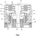
- the figure shows a highly simplified schematic sectional view of part of a vacuum pump.
- a rotor shaft 10 carries several rotor elements designed as rotor disks 12.
- Stator disks 16 are connected to an upper housing part 14 in the area of the turbomolecular stage or are carried by the upper housing part.
- a disk-shaped carrier 18 is firmly connected to the rotor shaft 10.
- the carrier 18 carries two rotor elements 20, 22 of a Holweck stage, designed as tubular cylinders.
- An inner stator device 24 of the Holweck stage is arranged between the rotor elements 20, 22 of the Holweck stage.
- the outer rotor element 22 is surrounded by a further stator device 26 of the Holweck stage, whereby this outer stator device 26 is connected in one piece to a second housing part 28 or is formed on the inside of the second housing part 28 in the exemplary embodiment shown.
- the rotor shaft 10 carries a drive device 30.
- the pressure-side end of the rotor shaft 10, which is the lower end in the figure, is carried by a rolling bearing 32.
- the rolling bearing 32 is arranged in a first housing part 34.
- the motor stator is firmly connected to a carrier part 36 for heat dissipation of the drive device 30 or the motor stator of the drive device 30.
- the connection is made in particular by pressing.
- the carrier part 36 also carries the stator device 24, which is also connected to the carrier part 36 by pressing.
- the carrier part 36 is then firmly connected to the second housing part 28 and in turn has good thermal conductivity. The intense heat generated in the area of the Holweck stage and the intense heat generated by the drive device 30 is thus conducted outwards into the second housing part 28 due to the good thermal conductivity of the pressings.
- the bearing 32 is connected to the first housing part 34.
- the first housing part 34 is connected to the second housing part 28, for example by means of screws or the like. If necessary, a seal 38 is also provided in this area.
- the thermal conductivity between the first housing part 34 and the second housing part 28 is as low as possible. This makes it possible to cool the first housing part 34 separately from the second housing part 28, so that the operating temperature of the bearing 32 can be reduced. This leads to an extension of the service life.
Landscapes
- Engineering & Computer Science (AREA)
- Mechanical Engineering (AREA)
- General Engineering & Computer Science (AREA)
- Physics & Mathematics (AREA)
- Thermal Sciences (AREA)
- Non-Positive Displacement Air Blowers (AREA)
Description
- Die Erfindung betrifft eine Vakuumpumpe, insbesondere eine Turbomolekularpumpe.
- Vakuumpumpen weisen eine Rotorwelle auf, die üblicherweise mit mehreren Rotorelementen verbunden ist. Bei den Rotorelementen handelt es sich beispielsweise bei einer Turbomolekularpumpe um mehrere im Wesentlichen radial zur Rotorwelle verlaufende Rotorscheiben. Zwischen den Rotorscheiben sind üblicherweise mit dem Gehäuse verbundene oder im Gehäuse angeordnete Statorscheiben, bei denen es sich somit um mehrere einzelne Statoreinrichtungen handelt, vorgesehen. Die einzelnen Statorscheiben sind somit zwischen benachbarten Rotorscheiben angeordnet. Ebenso kann es sich bei einem Rotorelement beispielsweise um rotierende Bauteile einer Holweckstufe, einer Siegbahnstufe oder Gaedestufe, sowie auch um einen Rotor eines Seitenkanalverdichters, handeln. Insbesondere in derartigen Pumpentypen treten aufgrund der Verdichtung hohe Temperaturen auf. Die Rotorwelle der Vakuumpumpe ist ferner mit einer Antriebseinrichtung wie einem Elektromotor verbunden. Auch derartige Bauteile erzeugen häufig hohe Temperaturen. Es ist daher erforderlich, dass derartige stark wärmeerzeugende Bauteile gekühlt werden.
- Die Rotorwelle ist von Lagern getragen. Insbesondere Wälzlager sind jedoch temperaturempfindlich. Bei hohen Betriebstemperaturen sinkt die Lebensdauer der Wälzlager. Häufig sind die Lager, insbesondere das druckseitig angeordnete Lager, auf engem Bauraum und insofern nahe der elektrischen Antriebseinheit, sowie auch des Bereichs, in dem eine hohe Gasverdichtung und somit hohe Verlustwärme erzeugt wird, angeordnet. Dies führt dazu, dass die Lager bei hoher Betriebstemperatur betrieben werden.
- Die Druckschrift
WO 94/00694 A1 - Die Druckschrift
DE 39 32 228 A1 beschreibt eine Turbovakuumpumpe mit einem Umfangsstromlaufrad und einem einstückigen Stator. - Aufgabe der Erfindung ist es mit konstruktiv einfachen Mitteln die Betriebstemperatur von Lagern, insbesondere Wälzlagern, bei Vakuumpumpen zu verringern.
- Die Lösung der Aufgabe erfolgt erfindungsgemäß durch die Merkmale des Anspruchs 1.
- Eine Vakuumpumpe weist eine Rotorwelle und mindestens ein Rotorelement auf. Ferner ist mindestens eine mit dem mindestens einen Rotorelement zusammenwirkende Statoreinrichtung vorgesehen. Desweiteren ist mit der Rotorwelle eine elektrische Antriebseinrichtung, sowie die Rotorwelle tragende Lager verbunden. Desweiteren weist die Vakuumpumpe ein Gehäuse auf, in dem die Bauteile der Pumpe angeordnet sind. Insbesondere trägt das Gehäuse über die Lager die Rotorwelle. Ferner ist mit dem Gehäuse mittelbar oder unmittelbar die mindestens eine Statoreinrichtung verbunden. Erfindungsgemäß weist das Gehäuse mehrere Gehäuseteile auf, wobei wärmeempfindliche Bauteile mit einem ersten Gehäuseteil und stark wärmeerzeugende Bauteile mit einem zweiten Gehäuseteil verbunden sind. Aufgrund dieser Anordnung ist es möglich, dass die beispielsweise im Verdichterteil und/oder von der Antriebseinrichtung erzeugte starke Wärme abgeführt wird, sodass die Betriebstemperatur wärmeempfindlicher Bauteile reduziert werden kann, wobei es sich bei dem wärmeempfindlichen Bauteil um eines der Lager handelt. Erfindungsgemäß wird somit die innerhalb der Pumpe erzeugte starke Wärme nur möglichst wenig in das Lager eingebracht. Dies ist erfindungsgemäß durch eine einfache konstruktive Maßnahme gelöst, da das Gehäuse mindestens zwei Gehäuseteile aufweist, und diese entweder die wärmeempfindlichen Bauteile oder die stark wärmeerzeugenden Bauteile tragen.
- Das zweite Gehäuseteil ist wärmeleitfähig mit der Antriebseinrichtung verbunden. Hierdurch kann die von der Antriebseinrichtung erzeugte Wärme auf einfache Weise abgeführt werden. In der bevorzugten Weiterbildung ist das zweite Gehäuseteil über ein Trägerteil mit der Antriebseinrichtung verbunden. Hierdurch ist insbesondere die Montage vereinfacht. Das zweite Gehäuseteil ist mit dem Trägerteil verpresst. Ferner ist es desweiteren bevorzugt, dass das Trägerteil weitere Bauteile trägt, über die Wärme zum zweiten Gehäuseteil abgeführt werden kann. Insbesondere handelt es sich hierbei um Bauteile die mit dem Verdichtungsbereich in Verbindung stehen, sodass aus diesem die Wärme zum zweiten Gehäuseteil abgeführt wird. Bevorzugt ist es somit, dass mit der Trägereinrichtung zumindest eine Statoreinrichtung verbunden ist. Hierbei kann es sich insbesondere um Statoreinrichtungen der Holweckstufe, der Siegbahnstufe, der Gaedestufe oder eines Seitenkanalverdichters handeln. Eine Verbindung mit derartigen Statoreinrichtungen ist insbesondere vorteilhaft, da in derartigen Stufen eine hohe Verdichtung und insofern eine hohe Wärmeerzeugung erfolgt.
- In besonders bevorzugter Ausführungsform ist das zweite Gehäuseteil daher mit der Antriebseinrichtung und/oder mindestens einer Statoreinrichtung gut wärmeleitend verbunden. Die Verbindung erfolgt insbesondere über ein Verpressen der Bauteile mit Übermaß. Hierdurch kann eine gute Wärmeleitung verwirklicht werden.
- Gemäß der Erfindung ist das erste Gehäuseteil mit einem Lager, insbesondere dem druckseitigen Lager, verbunden. Das druckseitige Lager ist insbesondere bei einer kompakten Bauweise der Vakuumpumpe stark von der Wärmeentwicklung der Antriebsweinrichtung und/oder des Verdichtungsbereichs der Pumpe beeinflusst. Dies ist insbesondere der Fall, wenn dieses Lager von einer Holweckstufe oder dergleichen umgeben ist.
- Bei einer weiteren bevorzugten Weiterbildung ist das erste Gehäuseteil zusätzlich mit einer insbesondere nur wenig wärmeerzeugenden Steuereinrichtung verbunden.
- Erfindungsgemäß sind das erste Gehäuseteil und das zweite Gehäuseteil über eine geringe Wärmeleitfähigkeit aufweisende Verbindung miteinander verbunden sind, Hierbei handelt es sich beispielsweise um eine Verschraubung, wobei gegebenenfalls ein Dichteelement wie ein Luftspalt oder dergleichen vorgesehen sein kann. Insbesondere ist es auch möglich, dass die Kammern der beiden Gehäuseteile thermisch voneinander entkoppelt sind.
- Durch das Vorsehen zweier gesonderter Gehäuseteile ist es möglich diese auf unterschiedlichem Temperaturniveau durch eine gesonderte Kühlung zu halten. Insbesondere kann das erste Gehäuseteil stärker gekühlt werden, sodass die Betriebstemperatur des Lagers und/oder einer Steuereinrichtung gering ist. Hierdurch kann beispielsweise die Lebensdauer eines Lagers deutlich erhöht werden. Dies wäre bei nicht getrennten Gehäuseteilen nur möglich, indem auch die stark wärmeerzeugenden Bauteile stark gekühlt würden. Dies würde einen erheblich höheren Energieaufwand mit sich bringen.
- Das Verbinden der stark wärmeerzeugenden Bauteile über ein Trägerteil insbesondere durch Verpressen hat ferner den Vorteil, dass neben einer guten Wärmeübertragung auch die Positionierung dieser Bauteile sehr exakt definiert ist. Dies ist insbesondere hinsichtlich eines von dem Trägerteil getragenen Stators einer Holweckstufe oder dergleichen zweckmäßig. Bevorzugt ist es ferner, dass mit dem Trägerteil der Stator des Motors durch Verpressen verbunden ist. Hierdurch ist auch die Position des Motorstators eindeutig definiert.
- Nachfolgend wird die Erfindung anhand einer bevorzugten Ausführungsform unter Bezugnahme auf die anliegende Zeichnung näher erläutert.
- Die Figur zeigt eine stark vereinfachte schematische Schnittansicht eines Teils einer Vakuumpumpe.
- In der in der Figur schematisch dargestellten Vakuumpumpe trägt eine Rotorwelle 10 mehrere als Rotorscheiben 12 ausgebildete Rotorelemente. Mit einem oberen Gehäuseteil 14 sind im Bereich der Turbomolekularstufe Statorscheiben 16 verbunden bzw. werden von dem oberen Gehäuseteil getragen.
- Desweiteren ist mit der Rotorwelle 10 ein scheibenförmiger Träger 18 fest verbunden. Der Träger 18 trägt im dargestellten Ausführungsbeispiel zwei als Rohrzylinder ausgebildete Rotorelemente 20, 22 einer Holweckstufe. Zwischen den Rotorelementen 20, 22 der Holweckstufe ist eine innere Statoreinrichtung 24 der Holweckstufe angeordnet. Das äußere Rotorelement 22 ist von einer weiteren Statoreinrichtung 26 der Holweckstufe umgeben, wobei diese äußere Statoreinrichtung 26 im dargestellten Ausführungsbeispiel einstückig mit einem zweiten Gehäuseteil 28 verbunden bzw. an der Innenseite des zweiten Gehäuseteils 28 ausgebildet ist.
- Desweiteren trägt die Rotorwelle 10 eine Antriebseinrichtung 30. Das druckseitige, in der Figur untere Ende der Rotorwelle 10 ist von einem Wälzlager 32 getragen. Das Wälzlager 32 ist in einem ersten Gehäuseteil 34 angeordnet.
- Im dargestellten Ausführungsbeispiel ist zur Wärmeabfuhr der Antriebseinrichtung 30 bzw. des Motorstators der Antriebseinrichtung 30 der Motorstator fest mit einem Trägerteil 36 verbunden. Die Verbindung erfolgt insbesondere durch Verpressen. Das Trägerteil 36 trägt ferner die Statoreinrichtung 24, die ebenfalls durch Verpressen mit dem Trägerteil 36 verbunden ist. Das Trägerteil 36 ist sodann fest und wiederum gut wärmeleitfähig mit dem zweiten Gehäuseteil 28 verbunden. Die im Bereich der Holweckstufe erzeugte starke Wärme, sowie die von der Antriebseinrichtung 30 erzeugte starke Wärme wird somit aufgrund der gut wärmeleitfähigen Verpressungen nach außen in das zweite Gehäuseteil 28 eingeleitet.
- Getrennt hiervon ist das Lager 32 mit dem ersten Gehäuseteil 34 verbunden. Das erste Gehäuseteil 34 ist beispielweise mittels Schrauben oder dergleichen mit dem zweiten Gehäuseteil 28 verbunden. Gegebenenfalls ist in diesem Bereich zusätzlich eine Dichtung 38 vorgesehen. Insbesondere ist die Wärmeleitfähigkeit zwischen dem ersten Gehäuseteil 34 und dem zweiten Gehäusetel 28 möglichst gering. Es ist hierdurch möglich das erste Gehäuseteil 34 gesondert von dem zweiten Gehäuseteil 28 zu kühlen, sodass die Betriebstemperatur des Lagers 32 reduziert werden kann. Dies führt zu einer Verlängerung der Lebensdauer.
Claims (6)
- Vakuumpumpe insbesondere Turbomolekularpumpe, mitmit einer Rotorwelle (10) verbundenen Rotorelementen (20, 22),mindestens einer mit einem Rotorelement (20, 22) zusammenwirkenden Statoreinrichtung (24, 26),einer die Rotorwelle (10) antreibenden elektrischen Antriebseinrichtung (30),die Rotorwelle (10) tragenden Lagern (32) undeinem mehrere Gehäuseteile (14, 28, 34) aufweisenden Gehäuse,wobei wärmeempfindliche Bauteile (32) mit einemersten Gehäuseteil (34) und stark wärmeerzeugende Bauteile (30, 24, 26) wie die Antriebseinrichtung (30) mit einem zweiten Gehäuseteil (28) verbunden sind, unddas zweite Gehäuseteil (28) wärmeleitfähig mit der Antriebseinrichtung (30) verbunden ist,dadurch gekennzeichnet, dassdas zweite Gehäuseteil (28) über ein Trägerteil (36) mit der Antriebseinrichtung (30) verbunden ist, wobei das erste Gehäuseteil (34) und das zweite Gehäuseteil (28) mittels einer gering wärmeleitfähig aufweisenden Verbindung miteinander verbunden sind, oder thermisch voneinander entkoppelt sind,wobei das zweite Gehäuseteil (28) mit dem Trägerteil (36) verpresst ist und wobei es sich bei dem wärmeempfindlichen Bauteil um eines der Lager handelt.
- Vakuumpumpe nach Anspruch 1, dadurch gekennzeichnet, dass mit dem Trägerteil (36) zumindest eine Statoreinrichtung (24) insbesondere einer Holweckstufe, einer Siegbahnstufe, einer Gaedestufe oder eines Seitenkanalverdichters verbunden ist.
- Vakuumpumpe nach den Ansprüchen 1 - 2, dadurch gekennzeichnet, dass das zweite Gehäuseteil (28) mit der Antriebseinrichtung (30) und/oder der Statoreinrichtung (24) gut wärmeleitfähig verbunden, insbesondere verpresst ist.
- Vakuumpumpe nach den Ansprüchen 1 - 3, dadurch gekennzeichnet, dass das erste Gehäuseteil (34) mit dem druckseitigen Lager (32) verbunden ist.
- Vakuumpumpe nach den Ansprüchen 1 - 4, dadurch gekennzeichnet, dass das erste Gehäuseteil (34) mit einer insbesondere wenig wärmerzeugenden Steuereinrichtung verbunden ist.
- Vakuumpumpe nach den Ansprüchen 1 - 5, dadurch gekennzeichnet, dass das erste Gehäuseteil (34) und das zweite Gehäuseteil (28) mit einer gesonderten Kühleinrichtung verbunden sind.
Applications Claiming Priority (2)
| Application Number | Priority Date | Filing Date | Title |
|---|---|---|---|
| DE202013008470.7U DE202013008470U1 (de) | 2013-09-24 | 2013-09-24 | Vakuumpumpe |
| PCT/EP2014/069344 WO2015043962A1 (de) | 2013-09-24 | 2014-09-11 | Vakuumpumpe |
Publications (3)
| Publication Number | Publication Date |
|---|---|
| EP3049676A1 EP3049676A1 (de) | 2016-08-03 |
| EP3049676B1 EP3049676B1 (de) | 2019-07-10 |
| EP3049676B2 true EP3049676B2 (de) | 2024-10-02 |
Family
ID=51518781
Family Applications (1)
| Application Number | Title | Priority Date | Filing Date |
|---|---|---|---|
| EP14761870.6A Active EP3049676B2 (de) | 2013-09-24 | 2014-09-11 | Vakuumpumpe |
Country Status (4)
| Country | Link |
|---|---|
| US (1) | US10221864B2 (de) |
| EP (1) | EP3049676B2 (de) |
| DE (1) | DE202013008470U1 (de) |
| WO (1) | WO2015043962A1 (de) |
Families Citing this family (5)
| Publication number | Priority date | Publication date | Assignee | Title |
|---|---|---|---|---|
| DE202013008470U1 (de) | 2013-09-24 | 2015-01-08 | Oerlikon Leybold Vacuum Gmbh | Vakuumpumpe |
| JP7680226B2 (ja) * | 2021-03-04 | 2025-05-20 | エドワーズ株式会社 | 真空ポンプ |
| EP4273405B1 (de) * | 2023-09-20 | 2025-07-09 | Pfeiffer Vacuum Technology AG | Vakuumpumpe mit einer holweck-pumpstufe mit veränderlicher holweck-geometrie |
| CN119321423B (zh) * | 2024-10-11 | 2025-06-13 | 北京中科科仪股份有限公司 | 分子泵散热结构及分子泵散热系统 |
| EP4549740A3 (de) * | 2025-03-19 | 2025-10-22 | Pfeiffer Vacuum Technology AG | Strömungstechnisch- und temperaturoptimierte vakuumpumpe |
Citations (2)
| Publication number | Priority date | Publication date | Assignee | Title |
|---|---|---|---|---|
| EP1760319A1 (de) † | 2004-06-25 | 2007-03-07 | Osaka Vacuum, Ltd. | Lagerstützkonstruktion für turbomolekulare pumpe |
| DE602004012546T2 (de) † | 2003-04-29 | 2009-04-16 | Edwards Ltd., Crawley | Vakuumpumpe |
Family Cites Families (15)
| Publication number | Priority date | Publication date | Assignee | Title |
|---|---|---|---|---|
| DE3508483A1 (de) * | 1985-03-09 | 1986-10-23 | Leybold-Heraeus GmbH, 5000 Köln | Gehaeuse fuer eine turbomolekularvakuumpumpe |
| JPS62168993A (ja) | 1985-11-27 | 1987-07-25 | Shimadzu Corp | ヒ−トパイプ冷却式タ−ボ分子ポンプ |
| DE3613344A1 (de) | 1986-04-19 | 1987-10-22 | Pfeiffer Vakuumtechnik | Turbomolekular-vakuumpumpe fuer hoeheren druck |
| US5020969A (en) | 1988-09-28 | 1991-06-04 | Hitachi, Ltd. | Turbo vacuum pump |
| US5577883A (en) * | 1992-06-19 | 1996-11-26 | Leybold Aktiengesellschaft | Gas friction vacuum pump having a cooling system |
| DE19702456B4 (de) | 1997-01-24 | 2006-01-19 | Pfeiffer Vacuum Gmbh | Vakuumpumpe |
| US6926493B1 (en) * | 1997-06-27 | 2005-08-09 | Ebara Corporation | Turbo-molecular pump |
| DE60037353T2 (de) | 1999-02-19 | 2008-12-04 | Ebara Corp. | Turbomolekularpumpe |
| DE10107341A1 (de) | 2001-02-16 | 2002-08-29 | Pfeiffer Vacuum Gmbh | Vakuumpumpe |
| JP2003269369A (ja) | 2002-03-13 | 2003-09-25 | Boc Edwards Technologies Ltd | 真空ポンプ |
| JP2010025122A (ja) | 2003-02-18 | 2010-02-04 | Osaka Vacuum Ltd | 分子ポンプの断熱構造 |
| JP4703279B2 (ja) | 2004-06-25 | 2011-06-15 | 株式会社大阪真空機器製作所 | 複合分子ポンプの断熱構造 |
| JP5420323B2 (ja) | 2009-06-23 | 2014-02-19 | 株式会社大阪真空機器製作所 | 分子ポンプ |
| NO20110786A1 (no) | 2011-05-31 | 2012-12-03 | Fmc Kongsberg Subsea As | Subsea kompressor direkte drevet av en permanentmagnetmotor med en stator og rotor nedsunket i vaeske |
| DE202013008470U1 (de) | 2013-09-24 | 2015-01-08 | Oerlikon Leybold Vacuum Gmbh | Vakuumpumpe |
-
2013
- 2013-09-24 DE DE202013008470.7U patent/DE202013008470U1/de not_active Expired - Lifetime
-
2014
- 2014-09-11 WO PCT/EP2014/069344 patent/WO2015043962A1/de not_active Ceased
- 2014-09-11 US US15/022,448 patent/US10221864B2/en active Active
- 2014-09-11 EP EP14761870.6A patent/EP3049676B2/de active Active
Patent Citations (2)
| Publication number | Priority date | Publication date | Assignee | Title |
|---|---|---|---|---|
| DE602004012546T2 (de) † | 2003-04-29 | 2009-04-16 | Edwards Ltd., Crawley | Vakuumpumpe |
| EP1760319A1 (de) † | 2004-06-25 | 2007-03-07 | Osaka Vacuum, Ltd. | Lagerstützkonstruktion für turbomolekulare pumpe |
Also Published As
| Publication number | Publication date |
|---|---|
| EP3049676A1 (de) | 2016-08-03 |
| WO2015043962A1 (de) | 2015-04-02 |
| US10221864B2 (en) | 2019-03-05 |
| EP3049676B1 (de) | 2019-07-10 |
| US20160298649A1 (en) | 2016-10-13 |
| DE202013008470U1 (de) | 2015-01-08 |
Similar Documents
| Publication | Publication Date | Title |
|---|---|---|
| EP3049676B2 (de) | Vakuumpumpe | |
| EP3899284B1 (de) | Seitenkanalverdichter für ein brennstoffzellensystem zur förderung und/oder verdichtung eines gasförmigen mediums | |
| DE19702456B4 (de) | Vakuumpumpe | |
| EP2310687B1 (de) | Vakuumpumpe | |
| EP3207567A1 (de) | Antriebsvorrichtung für einen kraftfahrzeugantriebsstrang | |
| EP2846044B1 (de) | Vakuumpumpe sowie anordnung mit einer vakuumpumpe | |
| DE102019002392A1 (de) | Wärmesperre | |
| DE102009055888A1 (de) | Vakuumpumpe | |
| EP2772650B1 (de) | Vakuumpumpe | |
| EP3472470A1 (de) | Elektrische fluidpumpe für ein kraftfahrzeug | |
| EP3315802A1 (de) | Rotationssystem mit axialer gaslagerung | |
| EP2063139B1 (de) | Pumpenaggregat | |
| EP3657022B1 (de) | Vakuumpumpe mit einem peltierelement | |
| EP3012459A2 (de) | Vakuumpumpe | |
| EP3112688A1 (de) | Splitflow-vakuumpumpe sowie vakuum-system mit einer splitflow-vakuumpumpe | |
| DE19804768B4 (de) | Rotorlagerung für eine Gasreibungspumpe | |
| EP3460249B1 (de) | Splitflow-vakuumpumpe | |
| DE102015111049B4 (de) | Vakuumpumpe | |
| EP3069027B1 (de) | Vakuumpumpen-rotoreinrichtung sowie vakuumpumpe | |
| EP2626510A1 (de) | Kfz-Hilfsaggregat-Vakuumpumpe | |
| EP1447567B1 (de) | Vakuumpumpanordnung | |
| EP3335302B1 (de) | Elektrische maschine mit variablem kühlsystem | |
| WO2019201448A1 (de) | Funktionseinheit eines verdichtersystems | |
| EP3557071B1 (de) | Vakuumpumpe und verfahren zum betreiben derselben | |
| DE102016118040A1 (de) | Wärmeabführvorrichtung für Turbomolekularpumpe |
Legal Events
| Date | Code | Title | Description |
|---|---|---|---|
| PUAI | Public reference made under article 153(3) epc to a published international application that has entered the european phase |
Free format text: ORIGINAL CODE: 0009012 |
|
| 17P | Request for examination filed |
Effective date: 20160309 |
|
| AK | Designated contracting states |
Kind code of ref document: A1 Designated state(s): AL AT BE BG CH CY CZ DE DK EE ES FI FR GB GR HR HU IE IS IT LI LT LU LV MC MK MT NL NO PL PT RO RS SE SI SK SM TR |
|
| AX | Request for extension of the european patent |
Extension state: BA ME |
|
| RAP1 | Party data changed (applicant data changed or rights of an application transferred) |
Owner name: LEYBOLD GMBH |
|
| DAX | Request for extension of the european patent (deleted) | ||
| GRAP | Despatch of communication of intention to grant a patent |
Free format text: ORIGINAL CODE: EPIDOSNIGR1 |
|
| STAA | Information on the status of an ep patent application or granted ep patent |
Free format text: STATUS: GRANT OF PATENT IS INTENDED |
|
| RIC1 | Information provided on ipc code assigned before grant |
Ipc: F04D 19/04 20060101AFI20190312BHEP Ipc: F04D 29/58 20060101ALI20190312BHEP Ipc: F04D 25/06 20060101ALI20190312BHEP Ipc: F04D 29/056 20060101ALI20190312BHEP |
|
| INTG | Intention to grant announced |
Effective date: 20190408 |
|
| GRAS | Grant fee paid |
Free format text: ORIGINAL CODE: EPIDOSNIGR3 |
|
| GRAA | (expected) grant |
Free format text: ORIGINAL CODE: 0009210 |
|
| STAA | Information on the status of an ep patent application or granted ep patent |
Free format text: STATUS: THE PATENT HAS BEEN GRANTED |
|
| AK | Designated contracting states |
Kind code of ref document: B1 Designated state(s): AL AT BE BG CH CY CZ DE DK EE ES FI FR GB GR HR HU IE IS IT LI LT LU LV MC MK MT NL NO PL PT RO RS SE SI SK SM TR |
|
| REG | Reference to a national code |
Ref country code: GB Ref legal event code: FG4D Free format text: NOT ENGLISH |
|
| REG | Reference to a national code |
Ref country code: CH Ref legal event code: EP Ref country code: AT Ref legal event code: REF Ref document number: 1153857 Country of ref document: AT Kind code of ref document: T Effective date: 20190715 |
|
| REG | Reference to a national code |
Ref country code: DE Ref legal event code: R096 Ref document number: 502014012197 Country of ref document: DE |
|
| REG | Reference to a national code |
Ref country code: IE Ref legal event code: FG4D Free format text: LANGUAGE OF EP DOCUMENT: GERMAN |
|
| REG | Reference to a national code |
Ref country code: NL Ref legal event code: MP Effective date: 20190710 |
|
| REG | Reference to a national code |
Ref country code: LT Ref legal event code: MG4D |
|
| PG25 | Lapsed in a contracting state [announced via postgrant information from national office to epo] |
Ref country code: NL Free format text: LAPSE BECAUSE OF FAILURE TO SUBMIT A TRANSLATION OF THE DESCRIPTION OR TO PAY THE FEE WITHIN THE PRESCRIBED TIME-LIMIT Effective date: 20190710 Ref country code: PT Free format text: LAPSE BECAUSE OF FAILURE TO SUBMIT A TRANSLATION OF THE DESCRIPTION OR TO PAY THE FEE WITHIN THE PRESCRIBED TIME-LIMIT Effective date: 20191111 Ref country code: BG Free format text: LAPSE BECAUSE OF FAILURE TO SUBMIT A TRANSLATION OF THE DESCRIPTION OR TO PAY THE FEE WITHIN THE PRESCRIBED TIME-LIMIT Effective date: 20191010 Ref country code: NO Free format text: LAPSE BECAUSE OF FAILURE TO SUBMIT A TRANSLATION OF THE DESCRIPTION OR TO PAY THE FEE WITHIN THE PRESCRIBED TIME-LIMIT Effective date: 20191010 Ref country code: FI Free format text: LAPSE BECAUSE OF FAILURE TO SUBMIT A TRANSLATION OF THE DESCRIPTION OR TO PAY THE FEE WITHIN THE PRESCRIBED TIME-LIMIT Effective date: 20190710 Ref country code: LT Free format text: LAPSE BECAUSE OF FAILURE TO SUBMIT A TRANSLATION OF THE DESCRIPTION OR TO PAY THE FEE WITHIN THE PRESCRIBED TIME-LIMIT Effective date: 20190710 Ref country code: SE Free format text: LAPSE BECAUSE OF FAILURE TO SUBMIT A TRANSLATION OF THE DESCRIPTION OR TO PAY THE FEE WITHIN THE PRESCRIBED TIME-LIMIT Effective date: 20190710 Ref country code: HR Free format text: LAPSE BECAUSE OF FAILURE TO SUBMIT A TRANSLATION OF THE DESCRIPTION OR TO PAY THE FEE WITHIN THE PRESCRIBED TIME-LIMIT Effective date: 20190710 |
|
| PG25 | Lapsed in a contracting state [announced via postgrant information from national office to epo] |
Ref country code: AL Free format text: LAPSE BECAUSE OF FAILURE TO SUBMIT A TRANSLATION OF THE DESCRIPTION OR TO PAY THE FEE WITHIN THE PRESCRIBED TIME-LIMIT Effective date: 20190710 Ref country code: LV Free format text: LAPSE BECAUSE OF FAILURE TO SUBMIT A TRANSLATION OF THE DESCRIPTION OR TO PAY THE FEE WITHIN THE PRESCRIBED TIME-LIMIT Effective date: 20190710 Ref country code: IS Free format text: LAPSE BECAUSE OF FAILURE TO SUBMIT A TRANSLATION OF THE DESCRIPTION OR TO PAY THE FEE WITHIN THE PRESCRIBED TIME-LIMIT Effective date: 20191110 Ref country code: RS Free format text: LAPSE BECAUSE OF FAILURE TO SUBMIT A TRANSLATION OF THE DESCRIPTION OR TO PAY THE FEE WITHIN THE PRESCRIBED TIME-LIMIT Effective date: 20190710 Ref country code: GR Free format text: LAPSE BECAUSE OF FAILURE TO SUBMIT A TRANSLATION OF THE DESCRIPTION OR TO PAY THE FEE WITHIN THE PRESCRIBED TIME-LIMIT Effective date: 20191011 Ref country code: ES Free format text: LAPSE BECAUSE OF FAILURE TO SUBMIT A TRANSLATION OF THE DESCRIPTION OR TO PAY THE FEE WITHIN THE PRESCRIBED TIME-LIMIT Effective date: 20190710 |
|
| REG | Reference to a national code |
Ref country code: DE Ref legal event code: R026 Ref document number: 502014012197 Country of ref document: DE |
|
| PG25 | Lapsed in a contracting state [announced via postgrant information from national office to epo] |
Ref country code: TR Free format text: LAPSE BECAUSE OF FAILURE TO SUBMIT A TRANSLATION OF THE DESCRIPTION OR TO PAY THE FEE WITHIN THE PRESCRIBED TIME-LIMIT Effective date: 20190710 |
|
| PLBI | Opposition filed |
Free format text: ORIGINAL CODE: 0009260 |
|
| PG25 | Lapsed in a contracting state [announced via postgrant information from national office to epo] |
Ref country code: IT Free format text: LAPSE BECAUSE OF FAILURE TO SUBMIT A TRANSLATION OF THE DESCRIPTION OR TO PAY THE FEE WITHIN THE PRESCRIBED TIME-LIMIT Effective date: 20190710 Ref country code: PL Free format text: LAPSE BECAUSE OF FAILURE TO SUBMIT A TRANSLATION OF THE DESCRIPTION OR TO PAY THE FEE WITHIN THE PRESCRIBED TIME-LIMIT Effective date: 20190710 Ref country code: DK Free format text: LAPSE BECAUSE OF FAILURE TO SUBMIT A TRANSLATION OF THE DESCRIPTION OR TO PAY THE FEE WITHIN THE PRESCRIBED TIME-LIMIT Effective date: 20190710 Ref country code: EE Free format text: LAPSE BECAUSE OF FAILURE TO SUBMIT A TRANSLATION OF THE DESCRIPTION OR TO PAY THE FEE WITHIN THE PRESCRIBED TIME-LIMIT Effective date: 20190710 Ref country code: RO Free format text: LAPSE BECAUSE OF FAILURE TO SUBMIT A TRANSLATION OF THE DESCRIPTION OR TO PAY THE FEE WITHIN THE PRESCRIBED TIME-LIMIT Effective date: 20190710 |
|
| 26 | Opposition filed |
Opponent name: PFEIFFER VACUUM TECHNOLOGY AG Effective date: 20200326 |
|
| PG25 | Lapsed in a contracting state [announced via postgrant information from national office to epo] |
Ref country code: MC Free format text: LAPSE BECAUSE OF FAILURE TO SUBMIT A TRANSLATION OF THE DESCRIPTION OR TO PAY THE FEE WITHIN THE PRESCRIBED TIME-LIMIT Effective date: 20190710 Ref country code: CZ Free format text: LAPSE BECAUSE OF FAILURE TO SUBMIT A TRANSLATION OF THE DESCRIPTION OR TO PAY THE FEE WITHIN THE PRESCRIBED TIME-LIMIT Effective date: 20190710 Ref country code: SM Free format text: LAPSE BECAUSE OF FAILURE TO SUBMIT A TRANSLATION OF THE DESCRIPTION OR TO PAY THE FEE WITHIN THE PRESCRIBED TIME-LIMIT Effective date: 20190710 Ref country code: SK Free format text: LAPSE BECAUSE OF FAILURE TO SUBMIT A TRANSLATION OF THE DESCRIPTION OR TO PAY THE FEE WITHIN THE PRESCRIBED TIME-LIMIT Effective date: 20190710 Ref country code: IS Free format text: LAPSE BECAUSE OF FAILURE TO SUBMIT A TRANSLATION OF THE DESCRIPTION OR TO PAY THE FEE WITHIN THE PRESCRIBED TIME-LIMIT Effective date: 20200224 |
|
| REG | Reference to a national code |
Ref country code: CH Ref legal event code: PL |
|
| PLAX | Notice of opposition and request to file observation + time limit sent |
Free format text: ORIGINAL CODE: EPIDOSNOBS2 |
|
| PG2D | Information on lapse in contracting state deleted |
Ref country code: IS |
|
| PG25 | Lapsed in a contracting state [announced via postgrant information from national office to epo] |
Ref country code: LI Free format text: LAPSE BECAUSE OF NON-PAYMENT OF DUE FEES Effective date: 20190930 Ref country code: IE Free format text: LAPSE BECAUSE OF NON-PAYMENT OF DUE FEES Effective date: 20190911 Ref country code: CH Free format text: LAPSE BECAUSE OF NON-PAYMENT OF DUE FEES Effective date: 20190930 Ref country code: LU Free format text: LAPSE BECAUSE OF NON-PAYMENT OF DUE FEES Effective date: 20190911 |
|
| REG | Reference to a national code |
Ref country code: BE Ref legal event code: MM Effective date: 20190930 |
|
| PG25 | Lapsed in a contracting state [announced via postgrant information from national office to epo] |
Ref country code: BE Free format text: LAPSE BECAUSE OF NON-PAYMENT OF DUE FEES Effective date: 20190930 Ref country code: SI Free format text: LAPSE BECAUSE OF FAILURE TO SUBMIT A TRANSLATION OF THE DESCRIPTION OR TO PAY THE FEE WITHIN THE PRESCRIBED TIME-LIMIT Effective date: 20190710 |
|
| PLBB | Reply of patent proprietor to notice(s) of opposition received |
Free format text: ORIGINAL CODE: EPIDOSNOBS3 |
|
| REG | Reference to a national code |
Ref country code: AT Ref legal event code: MM01 Ref document number: 1153857 Country of ref document: AT Kind code of ref document: T Effective date: 20190911 |
|
| PG25 | Lapsed in a contracting state [announced via postgrant information from national office to epo] |
Ref country code: AT Free format text: LAPSE BECAUSE OF NON-PAYMENT OF DUE FEES Effective date: 20190911 |
|
| PG25 | Lapsed in a contracting state [announced via postgrant information from national office to epo] |
Ref country code: CY Free format text: LAPSE BECAUSE OF FAILURE TO SUBMIT A TRANSLATION OF THE DESCRIPTION OR TO PAY THE FEE WITHIN THE PRESCRIBED TIME-LIMIT Effective date: 20190710 |
|
| PG25 | Lapsed in a contracting state [announced via postgrant information from national office to epo] |
Ref country code: HU Free format text: LAPSE BECAUSE OF FAILURE TO SUBMIT A TRANSLATION OF THE DESCRIPTION OR TO PAY THE FEE WITHIN THE PRESCRIBED TIME-LIMIT; INVALID AB INITIO Effective date: 20140911 Ref country code: MT Free format text: LAPSE BECAUSE OF FAILURE TO SUBMIT A TRANSLATION OF THE DESCRIPTION OR TO PAY THE FEE WITHIN THE PRESCRIBED TIME-LIMIT Effective date: 20190710 |
|
| APBM | Appeal reference recorded |
Free format text: ORIGINAL CODE: EPIDOSNREFNO |
|
| APBP | Date of receipt of notice of appeal recorded |
Free format text: ORIGINAL CODE: EPIDOSNNOA2O |
|
| APAH | Appeal reference modified |
Free format text: ORIGINAL CODE: EPIDOSCREFNO |
|
| APBM | Appeal reference recorded |
Free format text: ORIGINAL CODE: EPIDOSNREFNO |
|
| APBP | Date of receipt of notice of appeal recorded |
Free format text: ORIGINAL CODE: EPIDOSNNOA2O |
|
| APBQ | Date of receipt of statement of grounds of appeal recorded |
Free format text: ORIGINAL CODE: EPIDOSNNOA3O |
|
| APBQ | Date of receipt of statement of grounds of appeal recorded |
Free format text: ORIGINAL CODE: EPIDOSNNOA3O |
|
| PG25 | Lapsed in a contracting state [announced via postgrant information from national office to epo] |
Ref country code: MK Free format text: LAPSE BECAUSE OF FAILURE TO SUBMIT A TRANSLATION OF THE DESCRIPTION OR TO PAY THE FEE WITHIN THE PRESCRIBED TIME-LIMIT Effective date: 20190710 |
|
| P01 | Opt-out of the competence of the unified patent court (upc) registered |
Effective date: 20230423 |
|
| APBU | Appeal procedure closed |
Free format text: ORIGINAL CODE: EPIDOSNNOA9O |
|
| PUAH | Patent maintained in amended form |
Free format text: ORIGINAL CODE: 0009272 |
|
| STAA | Information on the status of an ep patent application or granted ep patent |
Free format text: STATUS: PATENT MAINTAINED AS AMENDED |
|
| 27A | Patent maintained in amended form |
Effective date: 20241002 |
|
| AK | Designated contracting states |
Kind code of ref document: B2 Designated state(s): AL AT BE BG CH CY CZ DE DK EE ES FI FR GB GR HR HU IE IS IT LI LT LU LV MC MK MT NL NO PL PT RO RS SE SI SK SM TR |
|
| REG | Reference to a national code |
Ref country code: DE Ref legal event code: R102 Ref document number: 502014012197 Country of ref document: DE |
|
| PGFP | Annual fee paid to national office [announced via postgrant information from national office to epo] |
Ref country code: DE Payment date: 20250929 Year of fee payment: 12 |
|
| PGFP | Annual fee paid to national office [announced via postgrant information from national office to epo] |
Ref country code: GB Payment date: 20250929 Year of fee payment: 12 |
|
| PGFP | Annual fee paid to national office [announced via postgrant information from national office to epo] |
Ref country code: FR Payment date: 20250925 Year of fee payment: 12 |