EP3047785A1 - Geschirrspülmaschine, insbesondere haushaltsgeschirrspülmaschine - Google Patents
Geschirrspülmaschine, insbesondere haushaltsgeschirrspülmaschine Download PDFInfo
- Publication number
- EP3047785A1 EP3047785A1 EP16150453.5A EP16150453A EP3047785A1 EP 3047785 A1 EP3047785 A1 EP 3047785A1 EP 16150453 A EP16150453 A EP 16150453A EP 3047785 A1 EP3047785 A1 EP 3047785A1
- Authority
- EP
- European Patent Office
- Prior art keywords
- pipe
- spray arm
- upper basket
- connection piece
- dishwasher according
- Prior art date
- Legal status (The legal status is an assumption and is not a legal conclusion. Google has not performed a legal analysis and makes no representation as to the accuracy of the status listed.)
- Granted
Links
Images




Classifications
-
- A—HUMAN NECESSITIES
- A47—FURNITURE; DOMESTIC ARTICLES OR APPLIANCES; COFFEE MILLS; SPICE MILLS; SUCTION CLEANERS IN GENERAL
- A47L—DOMESTIC WASHING OR CLEANING; SUCTION CLEANERS IN GENERAL
- A47L15/00—Washing or rinsing machines for crockery or tableware
- A47L15/42—Details
- A47L15/50—Racks ; Baskets
- A47L15/508—Hydraulic connections for racks
Definitions
- the invention relates to a dishwasher, in particular a domestic dishwasher, with a washing compartment providing a Spül necessarilyer receiving a height adjustable upper basket and an inside at least partially over the Spül actuallyer Wegwand extending inflow pipe, wherein on the upper basket a spray arm and a spray arm leading to the spray arm are arranged and wherein the Sprüharmrohr inflow pipe side has a funnel opening, which communicates with inserted into the washing container upper basket with a coupling device, which in turn is for supplying the Sprüharms with rinsing liquid in fluidic operative connection with the inflow pipe.
- a generic dishwasher is from the EP 1 742 563 B1 known.
- Dishwashers of the known type have a washing container, which provides a washing compartment.
- the washing compartment houses to be cleaned items to be cleaned, and for the arrangement of the items to be cleaned in the dishwasher crockery and / or cutlery baskets are used.
- a spraying device arranged within the washing container, which typically has spray arms arranged in a rotatable manner, serves.
- One of these spray arms is usually arranged on the underside of the upper basket at this.
- To supply this spray arm with rinsing liquor is also arranged on the upper basket Sprüharmrohr.
- the spray arm carried by the upper basket is fluidly coupled to the inlet pipe, so that a supply of the spray arm can be done with rinsing liquid.
- the upper basket is height adjustable, ie it can be in different Height positions are arranged within the washing compartment.
- it is from the EP 1 742 563 B1 known to use a swivel tube.
- This swivel tube runs horizontally over half the Spül actuallyer Wegwand and extends from a side wall to the middle of the washing container.
- the swivel tube acts on the coupling side with a funnel opening provided by the spray arm tube, which captures the swivel tube on the coupling side when the upper basket retracts into the flushing chamber.
- the required depending on the height positioning of the upper basket compensating movement of the pivot tube is due to a rotational movement of the pivot tube as an inclination thereof to the horizontal.
- the pivot tube rotates about a pivot point which is determined by the arrangement point of the pivot tube on the side wall.
- the inflow pipe is formed outside the washing compartment except for the section of the pivoting pipe.
- This proves to be a disadvantage for thermal reasons, since the promotion of the heated rinsing liquid to the spray arm leads to a heat release outside of the washing compartment.
- deflections are to be avoided for fluidic reasons.
- the waterways should be designed without detours to reduce the need for irrigation fluid. Therefore, laying paths for the inflow pipe have already been proposed, which extend exclusively within the rinsing container, in particular on a direct route to the spray arm, centrally along the rinsing container rear wall. In such a container inside laying eliminates the above-described pivot tube, so that a previously known in the manner described height adjustment to a height-adjustable upper basket is no longer possible.
- the object of the invention is therefore to propose an alternative construction for a vertically variable connection of a Sprüharmrohrs to an inflow pipe.
- the invention proposes a dishwasher of the type mentioned above, which is characterized in that the coupling device has a cooperating with the funnel opening of the Sprüharmrohrs pipe connection piece in the height direction of the Rinse container is designed to be movable.
- the coupling device according to the invention no longer has a pivot pipe, but via a pipe connection piece, which cooperates with the funnel opening of the Sprüharmrohres.
- This pipe connection piece is designed to be movable in the height direction of the washing container, which makes it possible to position it in dependence on the height alignment of the spray arm pipe carried by the upper basket.
- the pipe connection piece does not perform a twisting movement in contrast to the prior art. It is rather linearly movable formed, in the height direction of the washing.
- the movable design of the pipe connection piece in height direction provides the advantage that a stepless height adjustment of the pipe connection piece is allowed to the height position occupied by the upper basket.
- Another advantage of the pipe connection piece is that, with regard to its flow cross-section, it is designed to be optimized for the quantity of rinse liquid to be dispensed by the spray arm during operation.
- the upper basket is retracted after a user-side placement in the washing compartment of the washing.
- the funnel-shaped opening of the spray arm tube intercepts the pipe connection piece provided by the coupling device. This moves depending on the height orientation of the upper basket, if necessary, being guided by the funnel opening of the Sprüharmrohrs. It thus takes place as a result of retraction of the upper basket in the dishwasher automatic co-experience of the pipe connection piece, so that this is aligned after a proper introduction of the upper basket in the dishwasher in its height alignment to match the height orientation of the upper basket, ie the spray arm carried by it.
- the embodiment of the invention allows the formation of a symmetrically internal inlet pipe for the usually central spray arm, i. the spray arm carried by the upper basket, and this with high ease of use, as easy insertion and removal of the upper basket is guaranteed. It also ensures a smooth adjustment of Spülillonkeits Insert after a Korbeuxnver ein, which is also infinitely. A possible height variance of the upper basket by different basket loads can therefore be unnoticed balanced for the user.
- the inventive design allows to realize a larger diameter compared to the prior art for the rinsing liquid, since no separate connections are provided for different heights of the upper basket. It is only provided a pipe connection piece for all altitudes of the upper basket, which adapts to the respective Oberkorblage thanks to its displaceable arrangement in the height direction.
- the pipe connection piece funnel opening side provides a bevelled cross-sectional area. Because of this obliquely formed cross-sectional area of the pipe connection piece in the height direction upper edge is provided, which protrudes with respect to the lower peripheral edge funnel opening side. In the interaction with the funnel-shaped opening, a connection geometry is created which ensures that, if necessary, in the upper direction of the upper basket in the vertical direction a displacement of the pipe connection piece upwards or at a lower orientation of the upper basket in the vertical direction also a displacement of the pipe connection piece down automatically takes place.
- the pipe connection piece is arranged on one end of a flexible hose.
- This flexible hose is the actual fluidic connection between the inlet pipe on the one hand and the Sprüharmrohr other.
- the pipe connection piece represents so far an abutment for the funnel-shaped opening of the Sprüharmrohres, the as a result of the interaction with the funnel-shaped opening enables a positionally correct alignment of the hose leading in the operating case.
- Due to the flexibly formed hose can be formed by means of the coupling device, a fluidic connection between the inlet pipe on the one hand and Sprüharmrohr other hand, regardless of the altitude of the upper basket. It is not the flexible hose, but the one end arranged pipe fitting with the funnel opening of Sprüharmrohres in operative connection, whereby a direct contact of the hose with the funnel opening and the associated frictional resistance and material wear are avoided.
- the flexible hose On the other end of the flexible hose is connected according to a further feature of the invention to the inflow pipe. This can be done for example by means of an inflow pipe side flange of the hose.
- the flexible hose is pivotally mounted on the inflow pipe.
- This pivotable configuration makes it possible to align the hose depending on the height positioning of the upper basket to form a fluidic connection between the inlet pipe and the Sprüharmrohr.
- the pivotable arrangement of the tube is preferably achieved by its material-related flexibility.
- a material for the hose for example, silicone is considered, since it meets the requirements for durability with respect to the chemical and dynamic loads.
- a longitudinally displaceable arrangement of the hose is provided on the pipe fitting, ie a so-called floating bearing, which allows the pipe fitting and the hose relative to each other in the longitudinal direction of the hose can move.
- the pipe connection piece and the hose are preferably firmly connected to each other. This can be preferably realized, for example, such that the hose has a bellows contour.
- the mechanical stress of the coupling device is kept particularly low in all height positions of the upper basket and also in a change in the height position of the upper basket.
- the flexible hose is housed within a housing.
- This housing is part of the coupling device and houses the hose. Funnel opening side, the housing has the pipe connection piece, in which the hose opens funnel opening side.
- the housing has a connection section opposite the pipe connection piece, which serves for the longitudinally displaceable arrangement of the housing on a bearing plate. In this way, the height-adjustable arrangement of the pipe connection piece is guaranteed.
- the bearing plate is supported according to a further feature of the invention at the inlet pipe. It thus provides the linear bearing for the housing, including the pipe fitting provided. In the intended use case, therefore, a displacement in the height direction of the housing together with the provided pipe connection piece takes place in the height direction relative to the bearing plate supported by the inflow pipe, as a result of which there is a height adjustment of the coupling device depending on the height positioning of the upper basket.
- the pipe connection piece is arranged with interposition of a seal within the funnel-shaped opening of the Sprüharmrohrs, so that with the interposition of the flexible hose a fluidic connection between the inlet pipe and the Sprüharmrohr is formed to the right height.
- the coupling device is designed such that it maintains a position that it has taken with inserted upper basket, when the upper basket is pulled out of the washing container. This can be effected in particular by a suitable choice and condition of the hose. Additionally or alternatively, however, it is also possible for a clamping device to be provided with which the housing or the connecting section is held on the bearing plate in the assumed position. Preferably, this clamping device is designed in one piece with the holder of the inflow pipe at the Spül matterser Wegwand.
- Fig. 1 can be seen in a purely schematic representation of a washing container 2 of a dishwasher 1.
- the washing container 2 provides in a conventional manner, a washing compartment 3 ready, which serves to accommodate dishwashing crockets, not shown in detail in the figures, which in turn serve in the intended use case of receiving dishes to be cleaned.
- spray arm of a sprayer serves a centrally located within the washing tank 2 inlet pipe 5. This has the fluidic Coupling to a spray arm pipe 6 leading to the spray arm via a coupling device 9.
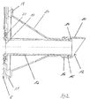
- FIG. 2 a perspective view
- Fig. 3 a partially sectioned side view shows.
- the coupling device 9 has a pipe connection piece 10. This is formed as part of a housing 17. This has the pipe connection piece 10 opposite via a connecting portion 18 which cooperates with a support plate 5 carried by the bearing plate 19. In this case, the bearing plate 19 rails 22 ready, which are encompassed by corresponding extensions of the connection section 18. Due to this configuration, a displaceable mounting of the housing 17 relative to the bearing plate 19 in the height direction 11 is realized.
- a clamping device 27 in the form of a clamping clip is present, which presses laterally against the extensions of the connecting portion 18 in order to keep the coupling device 9 in extension of the upper basket in the previously assumed position in the height direction 11.
- the bearing plate 19 also provides stops 23 and 24, by means of which a possible displacement movement of the housing 17 is limited relative to the bearing plate 19.
- the bearing plate 19 is U-shaped in cross-section and has side walls 25 which accomplish a fixed arrangement of the bearing plate 19 relative to the inlet pipe 5 by means of corresponding latching devices 26 and lateral recesses which enclose lateral protrusions on the inlet pipe 5 in the height direction 11.
- the housing 17 of the coupling device 9 and thus also the pipe connection piece 10 provided therefrom are designed to be movable in the height direction 11 relative to the inflow pipe 5.
- the pipe fitting 10 of the coupling device 9 cooperates with a provided by a funnel 7 funnel opening 8, wherein the funnel 7 is arranged at the end of the spray arm of the upper basket leading Sprüharmrohrs 6.
- the Coupling device 9 further via a flexible hose 13.
- This is laid inside the housing 17.
- the flexible hose 13 is in fluid communication with the inflow pipe 5, wherein a hose-side flange 21 is provided for the fluid-tight connection of the hose 13 to the inflow pipe 5, which abuts the outside of the inflow pipe 5.
- the flange 21 of the tube 13 may be clamped to the inflow pipe 5, welded or otherwise connected fluid-tight.
- the hose 13 is arranged to be longitudinally displaceable within the pipe connection piece 10.
- the hose 13 pipe connection piece side has a peripheral edge 14 which cooperates with a stop 15 which rotates on the inside from the pipe fitting 10.
- the hose 13 has a Faltenbalgkontur and the other end preferably not longitudinally displaceable, but is fixedly disposed within the pipe fitting 10.
- the hose on the other side may have approximately two outer ribs which enclose an inner rib on the pipe connecting piece 10.
- the pipe connection piece 10 On the outer circumference side, the pipe connection piece 10 also has a seal 16, which leads to a fluid-tight connection when the pipe connection piece 10 is inserted into the funnel 7 as intended.
- the vertical guidance of the housing 17, that is, the guidance of the housing 17 in the height direction 11 along the inflow pipe 5 allows a height positioning of the pipe fitting 10 carried by the housing 17 in relation to the Sprüharmrohr 6, and thus to a height positioning of the raised height adjustable from the washing container upper basket.
- Between the opening 20 at the inlet pipe 5 and the pipe fitting 10 is a hose connection by means of the flexible hose 13. This is held between the inlet pipe 5 to the Spül instrumentalgurwand 4 and the bearing plate 19, which forms the guide for the housing 17.
- the housing 17 and thus the pipe fitting 10 provided thereof is moved from the funnel-shaped opening 8 of the Sprüharmrohres 6 in the height position of the upper basket. This is based on two Example traversing movements in the FIGS. 4 to 6 on the one hand and the FIGS. 7 to 9 on the other hand shown.
- FIGS. 4 to 6 show an alignment of the upper basket and thus of the upper basket carried by Sprüharmrohrs 6 in a lower position.
- Fig. 4 is the coupling device 9 in a relation to the height direction 11 upper position.
- the funnel 7 catches the pipe fitting 10, as this Fig. 4 lets recognize.
- the upper peripheral edge of the chamfered cross-sectional surface 12 of the pipe fitting 10 runs against the inner wall of the funnel 7, which causes in a continued introduction of the upper basket to initiate a sliding movement of the housing 17 in the height direction 11 downward, as the other FIGS. 5 and 6 demonstrate.
- the housing 17 has moved downwards in the height direction 11 so that the pipe connection piece 10 comes to lie fluid-tight within the spray arm pipe 6, as a result of which a fluidic connection between the inlet pipe 5 and the spray arm pipe 6 is formed by means of the hose 13.
- FIGS. 7 to 9 show a movement of the housing 17 in another direction.
- Fig. 7 is a position of the housing 17 in a lower position, wherein the funnel 7 of the Sprüharmrohres 6 is in an upper position.
- the funnel 7 captures the housing 17 on the pipe connection piece side, wherein the pipe fitting 10 with its chamfered cross-sectional surface 12 runs on the inside of the funnel 7.
- a movement of the housing 17 in the height direction 11 causes upward, resulting in the other FIGS. 8 and 9 is shown.
- the pipe connection piece 10 is arranged fluid-tight within the Sprüharmrohres 6, so that via the hose 13, a fluidic connection between the inlet pipe 5 and the Sprüharmrohr 6 is formed.
Landscapes
- Washing And Drying Of Tableware (AREA)
Abstract
Description
- Die Erfindung betrifft eine Geschirrspülmaschine, insbesondere eine Haushaltsgeschirrspülmaschine, mit einem einen Spülraum bereitstellenden Spülbehälter, der einen höhenverstellbaren Oberkorb und ein sich innenseitig zumindest teilweise über die Spülbehälterrückwand erstreckendes Zuflussrohr aufnimmt, wobei an dem Oberkorb ein Sprüharm sowie ein zum Sprüharm führendes Sprüharmrohr angeordnet sind und wobei das Sprüharmrohr zuflussrohrseitig eine Trichteröffnung aufweist, die bei in den Spülbehälter eingeschobenem Oberkorb mit einer Kupplungseinrichtung in Verbindung steht, die ihrerseits zur Speisung des Sprüharms mit Spülflüssigkeit in strömungstechnischer Wirkverbindung mit dem Zuflussrohr steht.
- Eine gattungsgemäße Geschirrspülmaschine ist aus der
EP 1 742 563 B1 bekannt. - Geschirrspülmaschinen der vorbekannten Art verfügen über einen Spülbehälter, der einen Spülraum bereitstellt. Im bestimmungsgemäßen Verwendungsfall beherbergt der Spülraum zu reinigendes Spülgut, wobei zur Anordnung des zu reinigenden Spülguts im Spülraum Geschirr- und/oder Besteckkörbe zum Einsatz kommen. Es sind typischerweise zumindest ein Unterkorb und ein Oberkorb vorgesehen, die jeweils aus dem Spülbehälter verwenderseitig herausziehbar gelagert sind.
- Zur Beaufschlagung von zu reinigendem Spülgut mit Spülflüssigkeit dient eine innerhalb des Spülbehälters angeordnete Sprüheinrichtung, die typischerweise verdrehbar angeordnete Sprüharme aufweist. Einer dieser Sprüharme ist zumeist unterseitig des Oberkorbs an diesem angeordnet. Zur Versorgung dieses Sprüharms mit Spülflotte dient ein ebenfalls am Oberkorb angeordnetes Sprüharmrohr.
- Im bestimmungsgemäßen Verwendungsfall, wenn also der Oberkorb in den Spülbehälter eingeschoben ist, ist das vom Oberkorb getragene Sprüharmrohr an das Zuflussrohr strömungstechnisch angekoppelt, so dass eine Versorgung des Sprüharms mit Spülflüssigkeit erfolgen kann.
- Der Oberkorb ist höhenverstellbar ausgebildet, d.h. er kann in unterschiedlichen Höhenpositionen innerhalb des Spülraums angeordnet werden. Um trotz dieser Höhenverstellbarkeit des Oberkorbs einen strömungstechnischen Anschluss des Sprüharmrohrs an das Zuflussrohr gewährleisten zu können, ist es aus der
EP 1 742 563 B1 bekannt, ein Schwenkrohr einzusetzen. Dieses Schwenkrohr verläuft horizontal über die halbe Spülbehälterrückwand und erstreckt sich ausgehend von einer Seitenwand bis in die Mitte des Spülbehälters. Das Schwenkrohr wirkt ankoppelseitig mit einer vom Sprüharmrohr bereitgestellten Trichteröffnung zusammen, die das Schwenkrohr ankoppelseitig bei einem Einfahren des Oberkorbs in den Spülraum einfängt. Die je nach Höhenpositionierung des Oberkorbs dafür erforderliche Ausgleichsbewegung des Schwenkrohrs ergibt sich infolge einer Verdrehbewegung des Schwenkrohrs als Neigung desselben zur Horizontalen. Dabei verdreht das Schwenkrohr um einen Drehpunkt, der durch den Anordnungspunkt des Schwenkrohres an der Seitenwand bestimmt ist. - Obgleich sich die vorbeschriebene Ausgestaltung im alltäglichen Praxiseinsatz bewährt hat, besteht Verbesserungsbedarf. So ist gemäß vorbekannter Konstruktion das Zuflussrohr bis auf den Abschnitt des Schwenkrohres außerhalb des Spülraums ausgebildet. Dies erweist sich zum einen aus thermischen Gründen von Nachteil, da die Förderung der aufgeheizten Spülflüssigkeit zum Sprüharm zu einer Wärmeabgabe außerhalb des Spülraumes führt. Zum anderen sind aus strömungstechnischen Gründen Umlenkungen zu vermeiden. Darüber hinaus sind die Wasserwege möglichst ohne Umwege auszulegen, um den Bedarf an Spülflüssigkeit zu reduzieren. Es sind deshalb bereits Verlegewege für das Zuflussrohr vorgeschlagen worden, die ausschließlich innerhalb des Spülbehälters, insbesondere auf direktem Weg zum Sprüharm mittig entlang der Spülbehälterrückwand verlaufen. Bei einer solch behälterinnenseitigen Verlegung entfällt das vorbeschriebene Schwenkrohr, so dass eine in vorbeschriebener Weise vorbekannte Höhenanpassung an einen höhenverstellbaren Oberkorb nicht mehr möglich ist.
- Die Aufgabe der Erfindung ist es deshalb, eine alternative Konstruktion für einen höhenvariablen Anschluss eines Sprüharmrohrs an ein Zuflussrohr vorzuschlagen.
- Zur Lösung dieser Aufgabe wird mit der Erfindung eine Geschirrspülmaschine der eingangs genannten Art vorgeschlagen, die sich dadurch auszeichnet, dass die Kupplungseinrichtung ein mit der Trichteröffnung des Sprüharmrohrs zusammenwirkendes Rohranschlussstück aufweist, das in Höhenrichtung des Spülbehälters verfahrbar ausgebildet ist.
- Die Kupplungseinrichtung nach der Erfindung verfügt nicht mehr über ein Schwenkrohr, sondern über ein Rohranschlussstück, das mit der Trichteröffnung des Sprüharmrohres zusammenwirkt. Dieses Rohranschlussstück ist in Höhenrichtung des Spülbehälters verfahrbar ausgebildet, was es gestattet, eine Positionierung desselben in Abhängigkeit der Höhenausrichtung des vom Oberkorb getragenen Sprüharmrohrs vorzunehmen. Dabei vollführt das Rohranschlussstück im Unterschied zum Stand der Technik nicht eine Verdrehbewegung. Es ist vielmehr linear verfahrbar ausgebildet, und zwar in Höhenrichtung des Spülbehälters.
- Die verfahrbare Ausgestaltung des Rohranschlussstückes in Höhenrichtung erbringt den Vorteil mit sich, dass eine stufenlose Höhenanpassung des Rohranschlussstückes an die jeweils vom Oberkorb eingenommene Höhenposition gestattet ist. Von Vorteil des Rohranschlussstücks ist des Weiteren, dass dieses hinsichtlich seines Durchflussquerschnittes optimiert auf die vom Sprüharm im Betriebsfall abzugebende Spülflüssigkeitsmenge ausgebildet ist.
- Im bestimmungsgemäßen Verwendungsfall wird der Oberkorb nach einer verwenderseitigen Bestückung in den Spülraum des Spülbehälters eingefahren. Infolge dieser Einfahrbewegung fängt die trichterförmige Öffnung des Sprüharmrohres das von der Kupplungseinrichtung bereitgestellte Rohranschlussstück ein. Dieses verfährt je nach Höhenausrichtung des Oberkorbs erforderlichenfalls, wobei es von der Trichteröffnung des Sprüharmrohrs geführt ist. Es findet mithin eine infolge des Einfahren des Oberkorbs in den Spülraum automatische Mitverfahrung des Rohranschlussstückes statt, so dass dieses nach einem ordnungsgemäßen Einbringen des Oberkorbs in den Spülraum in seiner Höhenausrichtung passend zur Höhenausrichtung des Oberkorbs, d.h. des davon getragenen Sprüharmrohrs ausgerichtet ist. Da diese Höhenanpassung dank der linearen Verfahrbarkeit des Rohranschlussstückes stufenfrei ist, können verwenderseitig beliebige Positionierungen des Oberkorbs vorgesehen sein. Eine obere sowie eine untere Endlage des Oberkorbs ist durch die geometrische Ausgestaltung der Trichteröffnung bestimmt, d.h. diejenigen Positionen, in der die Trichteröffnung bei einem Einfahren des Oberkorbs das zugehörige Rohranschlussstück noch einfangen kann. Um eine verwenderseitige Fehlbelegung ausschließen zu können, sind maschinenseitig entsprechende Anschläge vorgesehen, so dass insoweit ungültige Höhenpositionen des Oberkorbs verwenderseitig nicht eingestellt werden können.
- Die erfindungsgemäße Ausgestaltung ermöglicht die Ausbildung eines symmetrisch innenliegenden Zuflussrohres für den in der Regel mittleren Sprüharm, d.h. den vom Oberkorb getragenen Sprüharm, und dies bei hohem Bedienkomfort, da ein leichtes Einschieben und Herausziehen des Oberkorbs gewährleistet ist. Es wird zudem eine leichtgängige Anpassung der Spülflüssigkeitsführung nach einer Korbhöhenverstellung gewährleistet, die zudem stufenlos ist. Eine etwaige Höhenvarianz des Oberkorbs durch unterschiedliche Korbbeladungen können mithin für den Verwender unbemerkbar ausgeglichen werden. Darüber hinaus gestattet es die erfindungsgemäße Ausgestaltung, einen im Vergleich zum Stand der Technik größeren Durchmesser für die Spülflüssigkeitsführung zu realisieren, da keine separaten Anschlüsse für unterschiedliche Höhenlagen des Oberkorbs vorgesehen sind. Es ist lediglich ein Rohranschlussstück für alle Höhenlagen des Oberkorbs vorgesehen, welches sich dank seiner verschieblichen Anordnung in Höhenrichtung an die jeweilige Oberkorblage anpasst.
- Es ist gemäß einem weiteren Merkmal der Erfindung vorgesehen, dass das Rohranschlussstück trichteröffnungsseitig eine abgeschrägt ausgebildete Querschnittsfläche bereitstellt. Aufgrund dieser schräg ausgebildeten Querschnittsfläche ist vom Rohranschlussstück eine in Höhenrichtung obere Randkante bereitgestellt, die mit Bezug auf die untere Randkante trichteröffnungsseitig vorspringt. In der Zusammenwirkung mit der trichterförmigen Öffnung ist so eine Anschlussgeometrie geschaffen, die dafür sorgt, dass bei einer in Höhenrichtung oberen Ausrichtung des Oberkorbs notwendigenfalls auch ein Verschieben des Rohranschlussstückes nach oben bzw. bei einer in Höhenrichtung unteren Ausrichtung des Oberkorbs notwendigenfalls auch ein Verschieben des Rohranschlussstückes nach unten automatisch stattfindet. Diese Funktionalität ist aufgrund des erfindungsgemäßen Rohranschlussstück mit abgeschrägt ausgebildeter Querschnittsfläche auch dann gewährleistet, wenn der untere Teil der Trichteröffnung des Sprüharmrohres vergleichsweise kurz ausgeführt ist. Dies wiederum erlaubt es, den Sprüharm möglichst lang auszubilden.
- Das Rohranschlussstück ist einendseitig eines flexiblen Schlauches angeordnet. Dieser flexible Schlauch dient der eigentlichen strömungstechnischen Verbindung zwischen dem Zuflussrohr einerseits und dem Sprüharmrohr andererseits. Das Rohranschlussstück stellt insoweit ein Widerlager für die trichterförmige Öffnung des Sprüharmrohres dar, das infolge des Zusammenwirkens mit der trichterförmigen Öffnung eine positionsgerechte Ausrichtung des im Betriebsfall die Spülflüssigkeit führenden Schlauches ermöglicht. Aufgrund des flexibel ausgebildeten Schlauches kann mittels der Kupplungseinrichtung eine strömungstechnische Verbindung zwischen Zuflussrohr einerseits und Sprüharmrohr andererseits unabhängig von der Höhenlage des Oberkorbs ausgebildet werden. Dabei stehen nicht der flexible Schlauch, sondern das daran einendseitig angeordnete Rohranschlussstück mit der Trichteröffnung des Sprüharmrohres in Wirkverbindung, womit ein direkter Kontakt des Schlauches mit der Trichteröffnung und der damit einhergehende Reibungswiderstand und Materialverschleiß vermieden sind.
- Anderendseitig ist der flexible Schlauch gemäß einem weiteren Merkmal der Erfindung an das Zuflussrohr angeschlossen. Dies kann beispielsweise mittels eines zuflussrohrseitigen Flansches des Schlauches erfolgen.
- Gemäß einem weiteren Merkmal der Erfindung ist vorgesehen, dass der flexible Schlauch verschwenkbeweglich am Zuflussrohr angeordnet ist. Diese verschwenkbewegliche Ausgestaltung gestattet es, den Schlauch in Abhängigkeit der Höhenpositionierung des Oberkorbs auszurichten, um eine strömungstechnische Verbindung zwischen dem Zuflussrohr und dem Sprüharmrohr auszubilden. Dabei ist die verschwenkbewegliche Anordnung des Schlauches bevorzugterweise durch seine materialbedingte Flexibilität erreicht. Als Material für den Schlauch kommt beispielsweise Silikon in Betracht, da es den Anforderungen zur Dauerbeständigkeit bezüglich der chemischen und dynamischen Belastungen entspricht. Um die mechanische Belastung der Verbindung zwischen Schlauch und Rohranschlussstück weitestgehend zu reduzieren, ist gemäß einer Ausführungsform der Erfindung eine längsverschiebliche Anordnung des Schlauches am Rohranschlussstück vorgesehen, d.h. eine sogenannte schwimmende Lagerung, die es gestattet, dass sich das Rohranschlussstück und der Schlauch relativ zueinander in Längsrichtung des Schlauches bewegen können. Eine andere Ausführungsform der Erfindung sieht vor, dass das Rohranschlussstück und der Schlauch vorzugsweise fest miteinander verbunden sind. Dies kann etwa vorzugsweise derart realisiert sein, dass der Schlauch eine Faltenbalgkontur aufweist. Bei dieser Ausführungsform wird die mechanische Belastung der Kupplungseinrichtung in allen Höhenpositionierungen des Oberkorbs und auch bei einer Veränderung der Höhenposionierung des Oberkorbs besonders gering gehalten.
- Gemäß einem weiteren Merkmal der Erfindung ist vorgesehen, dass der flexible Schlauch innerhalb eines Gehäuses untergebracht ist. Dieses Gehäuse ist Teil der Kupplungseinrichtung und beherbergt den Schlauch. Trichteröffnungsseitig weist das Gehäuse das Rohranschlussstück auf, in das der Schlauch trichteröffnungsseitig einmündet.
- Das Gehäuse weist ein dem Rohranschlussstück gegenüberliegenden Verbindungsabschnitt auf, der der längsverschieblichen Anordnung des Gehäuses an einer Lagerplatte dient. Auf diese Weise wird die höhenverstellbare Anordnung des Rohranschlussstückes gewährleistet.
- Die Lagerplatte stützt sich gemäß einem weiteren Merkmal der Erfindung am Zuflussrohr ab. Sie stellt mithin das Linearlager für das Gehäuse samt davon bereitgestelltem Rohranschlussstück bereit. Im bestimmungsgemäßen Verwendungsfall findet mithin ein Verschieben in Höhenrichtung des Gehäuses samt davon bereitgestelltem Rohranschlussstück in Höhenrichtung relativ zu der vom Zuflussrohr getragenen Lagerplatte statt, infolge dessen es zu einer Höhenanpassung der Kupplungseinrichtung in Abhängigkeit der Höhenpositionierung des Oberkorbs kommt. Sobald der Oberkorb in bestimmungsgemäßer Weise in den Spülraum der Geschirrspülmaschine verbracht ist, ist das Rohranschlussstück unter Zwischenordnung einer Dichtung innerhalb der trichterförmigen Öffnung des Sprüharmrohrs angeordnet, so dass unter Zwischenschaltung des flexiblen Schlauches eine strömungstechnische Verbindung zwischen dem Zuflussrohr und dem Sprüharmrohr höhenrichtig ausgebildet ist.
- In jedem Fall ist die Kupplungseinrichtung derart ausgebildet, dass sie eine Position, die sie bei eingeschobenem Oberkorb eingenommen hat, beibehält, wenn der Oberkorb aus dem Spülbehälter herausgezogen wird. Dies kann insbesondere durch geeignete Wahl und Beschaffenheit des Schlauches bewirkt werden. Zusätzlich oder alternativ kann aber auch eine Klemmeinrichtung vorhanden sein, mit der das Gehäuse bzw. der Verbindungsabschnitt an der Lagerplatte in der eingenommenen Position gehalten wird. Bevorzugterweise ist diese Klemmeinrichtung einteilig mit der Halterung des Zuflussrohres an der Spülbehälterrückwand ausgeführt.
- Weitere Merkmale und Vorteile der Erfindung ergeben sich aus der nachfolgenden Beschreibung anhand der Figuren. Dabei zeigen
- Fig. 1
- in rein schematisch perspektivischer Darstellung den Spülbehälter einer erfindungsgemäßen Geschirrspülmaschine;
- Fig. 2
- in schematischer Perspektivdarstellung eine erfindungsgemäße Kupplungseinrichtung;
- Fig. 3
- in teilgeschnittener Seitenansicht eine erfindungsgemäße Kupplungseinrichtung;
- Fig. 4
- in schematischer Seitenansicht eine Kupplungseinrichtung in einer oberen Stellung bei einer Trichteröffnung in einer unteren Stellung;
- Fig. 5
- in schematischer Seitenansicht eine Kupplungseinrichtung in einer mittleren Stellung bei einer Trichteröffnung in einer unteren Stellung;
- Fig. 6
- in schematischer Seitenansicht eine Kupplungseinrichtung in einer unteren Stellung bei einer Trichteröffnung in einer unteren Stellung;
- Fig. 7
- in schematischer Seitenansicht eine Kupplungseinrichtung in einer unteren Stellung bei einer Trichteröffnung in einer oberen Stellung;
- Fig.8
- in schematischer Seitenansicht eine Kupplungseinrichtung in einer mittleren Stellung bei einer Trichteröffnung in einer oberen Stellung; und
- Fig. 9
- in schematischer Seitenansicht eine Kupplungseinrichtung in einer oberen Stellung bei einer Trichteröffnung in einer oberen Stellung;
-
Fig. 1 lässt in rein schematischer Darstellung einen Spülbehälter 2 einer Geschirrspülmaschine 1 erkennen. Der Spülbehälter 2 stellt in an sich bekannter Weise einen Spülraum 3 bereit, der der Aufnahme von in den Figuren nicht näher dargezeigten Spülkörben dient, die ihrerseits im bestimmungsgemäßen Verwendungsfall der Aufnahme von zu reinigendem Spülgut dienen. - Zur Versorgung u.a. eines von einem Oberkorb getragenen und in den Figuren nicht näher dargestellten Sprüharms einer Sprüheinrichtung dient ein mittig innerhalb des Spülbehälters 2 verlegtes Zuflussrohr 5. Dieses verfügt zur strömungstechnischen Ankopplung an ein zum Sprüharm führendes Sprüharmrohr 6 über eine Kupplungseinrichtung 9.
- Die
Figuren 2 und3 lassen die Kupplungseinrichtung 9 im Detail erkennen, wobeiFig. 2 eine Perspektivansicht undFig. 3 eine teilgeschnittene Seitenansicht zeigt. - Die Kupplungseinrichtung 9 verfügt über ein Rohranschlussstück 10. Dieses ist als Teil eines Gehäuses 17 ausgebildet. Dieses verfügt dem Rohranschlussstück 10 gegenüberliegend über einen Verbindungsabschnitt 18, der mit einer vom Zuflussrohr 5 getragenen Lagerplatte 19 zusammenwirkt. Dabei stellt die Lagerplatte 19 Schienen 22 bereit, die von entsprechenden Fortsätzen des Verbindungsebschnitts 18 umgriffen sind. Aufgrund dieser Ausgestaltung ist eine verschiebliche Lagerung des Gehäuses 17 gegenüber der Lagerplatte 19 in Höhenrichtung 11 realisiert. Im Übrigen ist eine Klemmeinrichtung 27 in Form einer Klemmspange vorhanden, die seitlich gegen die Fortsätze des Verbindungsabschnitts 18 drückt, um die Kupplungseinrichtung 9 bei Ausfahren des Oberkorbes in der zuvor eingenommenen Position in Höhenrichtung 11 zu halten.
- Die Lagerplatte 19 stellt ferner Anschläge 23 und 24 bereit, mittels welcher eine mögliche Verschiebebewegung des Gehäuses 17 relativ gegenüber der Lagerplatte 19 begrenzt ist.
- Die Lagerplatte 19 ist im Querschnitt U-förmig ausgebildet und weist Seitenwandungen 25 auf, die mittels entsprechender Rasteinrichtungen 26 und seitlicher Aussparungen, welche seitliche Ausbuchtungen am Zuflussrohr 5 in Höhenrichtung 11 umschließen, eine ortsfeste Anordnung der Lagerplatte 19 relativ gegenüber dem Zuflussrohr 5 bewerkstelligen. Im Ergebnis dieser Ausgestaltung ergibt sich, dass das Gehäuse 17 der Kupplungseinrichtung 9 und damit auch das davon bereitgestellte Rohranschlussstück 10 in Höhenrichtung 11 relativ zum Zuflussrohr 5 verfahrbar ausgebildet sind.
- Wie insbesondere die perspektivische Darstellung nach
Fig. 2 erkennen lässt, wirkt das Rohranschlussstück 10 der Kupplungseinrichtung 9 mit einer von einem Trichter 7 bereitgestellten Trichteröffnung 8 zusammen, wobei der Trichter 7 endseitig des zum Sprüharm des Oberkorbs führenden Sprüharmrohrs 6 angeordnet ist. - Wie sich insbesondere aus der Darstellung nach
Fig. 3 ergibt, verfügt die Kupplungseinrichtung 9 des Weiteren über einen flexiblen Schlauch 13. Dieser ist innerhalb des Gehäuses 17 verlegt. Über eine Öffnung 20 im Zuflussrohr 5 steht der flexible Schlauch 13 in strömungstechnischer Verbindung mit dem Zuflussrohr 5, wobei zur fluiddichten Anbindung des Schlauches 13 an das Zuflussrohr 5 ein schlauchseitiger Flansch 21 vorgesehen ist, der außenseitig am Zuflussrohr 5 anliegt. Der Flansch 21 des Schlauches 13 kann mit dem Zuflussrohr 5 verklemmt, verschweißt oder sonst wie fluiddicht verbunden sein. - Anderendseitig ist der Schlauch 13 längsverschieblich innerhalb des Rohranschlussstücks 10 angeordnet. Um ein ungewünschtes Herausziehen des Schlauches 13 aus dem Rohranschlussstück 10 zu vermeiden, verfügt der Schlauch 13 rohranschlussstückseitig über einen umlaufenden Rand 14, der mit einem vom Rohranschlussstück 10 innenseitig umlaufenden Anschlag 15 zusammenwirkt.
- Eine nicht gezeigte Alternative sieht vor, dass der Schlauch 13 eine Faltenbalgkontur aufweist und anderendseitig vorzugsweise nicht längsverschieblich, sondern fest innerhalb des Rohranschlussstücks 10 angeordnet ist. Hierbei kann der Schlauch anderendseitig etwa zwei außenliegende Rippen aufweisen, die eine inneliegende Rippe am Rohranschlussstück 10 umschließen.
- Außenumfangsseitig verfügt das Rohranschlussstück 10 zudem über eine Dichtung 16, die bei einem bestimmungsgemäßen Einführen des Rohranschlussstücks 10 in den Trichter 7 zu einer fluiddichten Verbindung führt.
- Die vertikale Führung des Gehäuses 17, d.h. die Führung des Gehäuses 17 in Höhenrichtung 11 entlang des Zuflussrohres 5 gestattet eine Höhenpositionierung des vom Gehäuse 17 getragenen Rohranschlussstückes 10 in Relation zum Sprüharmrohr 6, mithin zu einer Höhenpositionierung des vom Spülbehälter höhenverstellbar aufgenommenen Oberkorbs. Zwischen der Öffnung 20 am Zuflussrohr 5 und dem Rohranschlussstück 10 besteht eine Schlauchverbindung mittels des flexiblen Schlauchs 13. Dieser wird zwischen dem Zuflussrohr 5 an der Spülbehälterrückwand 4 und der Lagerplatte 19, die die Führung für das Gehäuse 17 bildet, gehalten. Beim Einschieben des Oberkorbs in den Spülraum 3 wird das Gehäuse 17 und damit das davon bereitgestellte Rohranschlussstück 10 von der trichterförmigen Öffnung 8 des Sprüharmrohres 6 in die Höhenposition des Oberkorbs verfahren. Dies ist anhand zweier Beispielverfahrbewegungen in den
Figuren 4 bis 6 einerseits und denFiguren 7 bis 9 anderseits gezeigt. - Die
Figuren 4 bis 6 zeigen eine Ausrichtung des Oberkorbs und damit des vom Oberkorb getragenen Sprüharmrohrs 6 in einer unteren Position. Gemäß Ausgangssituation nachFig. 4 befindet sich die Kupplungseinrichtung 9 in einer mit Bezug auf die Höhenrichtung 11 oberen Position. Wird nun der Oberkorb in den Spülraum 3 eingefahren, so fängt der Trichter 7 das Rohranschlussstück 10 ein, wie diesFig. 4 erkennen lässt. Die obere Randkante der abgeschrägten Querschnittsfläche 12 des Rohranschlussstückes 10 läuft dabei gegen die Innenwandung des Trichters 7, was bei einer fortgesetzten Einführung des Oberkorbs zur Einleitung einer Verschiebebewegung des Gehäuses 17 in Höhenrichtung 11 nach unten bewirkt, wie dies die weiterenFiguren 5 und 6 zeigen. In der Endlage gemäßFig. 6 ist das Gehäuse 17 in Höhenrichtung 11 soweit nach unten gefahren, so dass das Rohranschlussstück 10 fluiddicht innerhalb des Sprüharmrohrs 6 zu liegen kommt, infolge dessen mittels des Schlauchs 13 eine strömungstechnische Verbindung zwischen dem Zuflussrohr 5 und dem Sprüharmrohr 6 ausgebildet ist. - Die
Figuren 7 bis 9 zeigen eine Verfahrbewegung des Gehäuses 17 in anderer Richtung. - Ausgangspunkt nach
Fig. 7 ist eine Stellung des Gehäuses 17 in einer unteren Position, wobei sich der Trichter 7 des Sprüharmrohres 6 in einer oberen Stellung befindet. Bei einem Einfahren des Oberkorbs in den Spülraum 3 fängt der Trichter 7 das Gehäuse 17 rohranschlussstückseitig, wobei das Rohranschlussstück 10 mit ihrer abgeschrägten Querschnittsfläche 12 innenseitig des Trichters 7 aufläuft. Infolge einer weiteren Einfahrbewegung des Oberkorbs in den Spülraum 3 wird eine Verfahrbewegung des Gehäuses 17 in Höhenrichtung 11 nach oben bewirkt, was in den weiterenFiguren 8 und 9 dargestellt ist. In der Endlage gemäßFig. 9 ist das Rohranschlussstück 10 fluiddicht innerhalb des Sprüharmrohres 6 angeordnet, so dass über den Schlauch 13 eine strömungstechnische Verbindung zwischen dem Zuflussrohr 5 und dem Sprüharmrohr 6 ausgebildet ist. -
- 1
- Geschirrspülmaschine
- 2
- Spülbehälter
- 3
- Spülraum
- 4
- Spülbehälterrückwand
- 5
- Zuflussrohr
- 6
- Sprüharmrohr
- 7
- Trichter
- 8
- Trichteröffnung
- 9
- Kupplungseinrichtung
- 10
- Rohranschlussstück
- 11
- Höhenrichtung
- 12
- Querschnittsfläche
- 13
- Schlauch
- 14
- Rand
- 15
- Anschlag
- 16
- Dichtung
- 17
- Gehäuse
- 18
- Verbindungsabschnitt
- 19
- Lagerplatte
- 20
- Öffnung
- 21
- Flansch
- 22
- Schiene
- 23
- Anschlag
- 24
- Anschlag
- 25
- Seitenwand
- 26
- Rasteinrichtung
- 27
- Klemmeinrichtung
Claims (11)
- Geschirrspülmaschine, mit einem einen Spülraum (3) bereitstellenden Spülbehälter (2), der einen höhenverstellbaren Oberkorb und ein sich innenseitig zumindest teilweise über die Spülbehälterrückwand (4) erstreckendes Zuflussrohr (5) aufnimmt, wobei an dem Oberkorb ein Sprüharm sowie ein zum Sprüharm führendes Sprüharmrohr (6) angeordnet sind und wobei das Sprüharmrohr (6) zuflussrohrseitig eine Trichteröffnung (8) aufweist, die bei in den Spülbehälter (3) eingeschobenem Oberkorb mit einer Kupplungseinrichtung (9) in Verbindung steht, die ihrerseits zur Speisung des Sprüharms mit Spülflüssigkeit in strömungstechnischer Wirkverbindung mit dem Zuflussrohr (5) steht, dadurch gekennzeichnet, dass die Kupplungseinrichtung (9) ein mit der Trichteröffnung (8) des Sprüharmrohrs (6) zusammenwirkendes Rohranschlussstück (10) aufweist, das in Höhenrichtung (11) des Spülbehälters (2) verfahrbar ausgebildet ist.
- Geschirrspülmaschine nach Anspruch 1,
dadurch gekennzeichnet, dass
das Rohranschlussstück (10) trichteröffnungsseitig eine abgeschrägt ausgebildete Querschnittsfläche (12) bereitstellt. - Geschirrspülmaschine nach Anspruch 1 oder 2,
dadurch gekennzeichnet, dass
das Rohranschlussstück (10) einendseitig eines flexiblen Schlauchs (13) angeordnet ist. - Geschirrspülmaschine nach Anspruch 3,
dadurch gekennzeichnet, dass
der flexible Schlauch (13) anderendseitig an das Zuflussrohr (5) angeschlossen ist. - Geschirrspülmaschine nach Anspruch 3 oder 4,
dadurch gekennzeichnet, dass
der flexible Schlauch (13) verschwenkbeweglich am Zuflussrohr (5) angeordnet ist. - Geschirrspülmaschine nach Anspruch 3, 4 oder 5,
dadurch gekennzeichnet, dass
der flexible Schlauch (13) innerhalb eines Gehäuses (17) untergebracht ist. - Geschirrspülmaschine nach Anspruch 6,
dadurch gekennzeichnet, dass
das Gehäuse (17) das Rohranschlussstück (10) aufweist. - Geschirrspülmaschine nach einem der Ansprüche 3 bis 7,
dadurch gekennzeichnet, dass
das Rohranschlussstück (10) den flexiblen Schlauch (13) längsverschieblich aufnimmt. - Geschirrspülmaschine nach einem der Ansprüche 3 bis 8,
dadurch gekennzeichnet, dass
das der Schlauch (13) zumindest abschnittsweise eine Faltenbalgkontur aufweist. - Geschirrspülmaschine nach einem der Ansprüche 6 bis 9,
dadurch gekennzeichnet, dass
das Gehäuse (17) dem Rohranschlussstück (10) gegenüberliegend einen Verbindungsabschnitt (18) zur längsverschieblichen Anordnung an einer Lagerplatte (19) aufweist. - Geschirrspülmaschine nach Anspruch 10,
dadurch gekennzeichnet, dass
sich die Lagerplatte (19) am Zuflussrohr (5) abstützt.
Applications Claiming Priority (1)
| Application Number | Priority Date | Filing Date | Title |
|---|---|---|---|
| DE102015100892 | 2015-01-22 |
Publications (2)
| Publication Number | Publication Date |
|---|---|
| EP3047785A1 true EP3047785A1 (de) | 2016-07-27 |
| EP3047785B1 EP3047785B1 (de) | 2017-08-09 |
Family
ID=55070905
Family Applications (1)
| Application Number | Title | Priority Date | Filing Date |
|---|---|---|---|
| EP16150453.5A Active EP3047785B1 (de) | 2015-01-22 | 2016-01-07 | Geschirrspülmaschine, insbesondere haushaltsgeschirrspülmaschine |
Country Status (1)
| Country | Link |
|---|---|
| EP (1) | EP3047785B1 (de) |
Cited By (3)
| Publication number | Priority date | Publication date | Assignee | Title |
|---|---|---|---|---|
| CN110013205A (zh) * | 2019-02-22 | 2019-07-16 | 宁波欧琳厨具有限公司 | 一种拼接式喷淋臂及洗碗机 |
| DE102024206777A1 (de) * | 2024-07-18 | 2026-01-22 | BSH Hausgeräte GmbH | Geschirrspülmaschine |
| DE102017114185B4 (de) * | 2016-07-01 | 2026-02-26 | Miele & Cie. Kg | Geschirrspülmaschine, insbesondere Haushaltsgeschirrspülmaschine |
Citations (4)
| Publication number | Priority date | Publication date | Assignee | Title |
|---|---|---|---|---|
| EP1110497A2 (de) * | 1999-12-17 | 2001-06-27 | ANTONIO MERLONI S.p.A. | Geschirrspülmaschine |
| EP1742563B1 (de) | 2004-05-03 | 2009-05-27 | Miele & Cie. KG | Geschirrspülmaschine mit einem höhenverstellbaren oberkorb |
| US20130068265A1 (en) * | 2011-09-15 | 2013-03-21 | General Electric Company | Two level conduit docking port mechanism for a dishwashing appliance |
| US20140373883A1 (en) * | 2013-06-24 | 2014-12-25 | Wolf Appliance, Inc. | Connector for a dishwasher middle spray arm |
-
2016
- 2016-01-07 EP EP16150453.5A patent/EP3047785B1/de active Active
Patent Citations (4)
| Publication number | Priority date | Publication date | Assignee | Title |
|---|---|---|---|---|
| EP1110497A2 (de) * | 1999-12-17 | 2001-06-27 | ANTONIO MERLONI S.p.A. | Geschirrspülmaschine |
| EP1742563B1 (de) | 2004-05-03 | 2009-05-27 | Miele & Cie. KG | Geschirrspülmaschine mit einem höhenverstellbaren oberkorb |
| US20130068265A1 (en) * | 2011-09-15 | 2013-03-21 | General Electric Company | Two level conduit docking port mechanism for a dishwashing appliance |
| US20140373883A1 (en) * | 2013-06-24 | 2014-12-25 | Wolf Appliance, Inc. | Connector for a dishwasher middle spray arm |
Cited By (4)
| Publication number | Priority date | Publication date | Assignee | Title |
|---|---|---|---|---|
| DE102017114185B4 (de) * | 2016-07-01 | 2026-02-26 | Miele & Cie. Kg | Geschirrspülmaschine, insbesondere Haushaltsgeschirrspülmaschine |
| CN110013205A (zh) * | 2019-02-22 | 2019-07-16 | 宁波欧琳厨具有限公司 | 一种拼接式喷淋臂及洗碗机 |
| CN110013205B (zh) * | 2019-02-22 | 2023-04-25 | 宁波欧琳科技股份有限公司 | 一种拼接式喷淋臂及洗碗机 |
| DE102024206777A1 (de) * | 2024-07-18 | 2026-01-22 | BSH Hausgeräte GmbH | Geschirrspülmaschine |
Also Published As
| Publication number | Publication date |
|---|---|
| EP3047785B1 (de) | 2017-08-09 |
Similar Documents
| Publication | Publication Date | Title |
|---|---|---|
| EP2192852B1 (de) | Geschirrspüler | |
| DE102004022025B3 (de) | Geschirrspülmaschine mit einem höhenverstellbaren Oberkorb | |
| DE102012106571B4 (de) | Staubsaugerdüse, insbesondere für Haushaltsstaubsauger | |
| EP2449934B1 (de) | Saugdüsenanordnung für einen Bodenstaubsauger | |
| EP3092937B1 (de) | Geschirrspülmaschine mit einer spülgutaufnahme und einer hebevorrichtung für die spülgutaufnahme | |
| EP2273910B1 (de) | Geschirrspülmaschine | |
| DE102013113458A1 (de) | Geschirrspüler mit vertikal verstellbarem spülgutkorb | |
| EP3047785B1 (de) | Geschirrspülmaschine, insbesondere haushaltsgeschirrspülmaschine | |
| DE19926962B4 (de) | Geschirrspülmaschine mit höhenverstellbarem Korb | |
| EP2449949B1 (de) | Geschirrspülmaschine | |
| DE4137227C2 (de) | Haushalt-Geschirrspülmaschine mit höhenverstellbarem Oberkorb | |
| EP3186430B1 (de) | Fluidanschlussvorrichtung für ein haushaltsgerät, sowie haushaltsgerät mit einer solchen fluidanschlussvorrichtung | |
| EP2201886B1 (de) | Spülgutträger mit einem Anschlussstück für schlauchförmiges Reinigungsgut | |
| DE102012224303B4 (de) | Geschirrspülmaschine, insbesondere Haushaltsgeschirrspülmaschine | |
| DE102017114185B4 (de) | Geschirrspülmaschine, insbesondere Haushaltsgeschirrspülmaschine | |
| DE202008006611U1 (de) | Ablaufgarnitur für Wasch- oder Spülbecken | |
| DE3702829C1 (de) | Geschirrkorb fuer eine frontseitig beschickbare Geschirrspuelmaschine | |
| EP3992382B1 (de) | Verwendung einer zur montage an einer schüssel ausgelegten duscheinrichtung | |
| DE102006061202B4 (de) | Bodendüse für Hartböden | |
| EP3025624B1 (de) | Kaffeeautomat | |
| DE202007018652U1 (de) | Bodendüse für Hartböden | |
| DE102006061193B3 (de) | Bodendüse für Hartböden | |
| WO2008028752A1 (de) | Bodendüse für hartböden | |
| WO2018028952A1 (de) | Haushaltsgeschirrspülmaschine | |
| DE102007015247A1 (de) | Hausgerätevorrichtung |
Legal Events
| Date | Code | Title | Description |
|---|---|---|---|
| PUAI | Public reference made under article 153(3) epc to a published international application that has entered the european phase |
Free format text: ORIGINAL CODE: 0009012 |
|
| AK | Designated contracting states |
Kind code of ref document: A1 Designated state(s): AL AT BE BG CH CY CZ DE DK EE ES FI FR GB GR HR HU IE IS IT LI LT LU LV MC MK MT NL NO PL PT RO RS SE SI SK SM TR |
|
| AX | Request for extension of the european patent |
Extension state: BA ME |
|
| 17P | Request for examination filed |
Effective date: 20170127 |
|
| RBV | Designated contracting states (corrected) |
Designated state(s): AL AT BE BG CH CY CZ DE DK EE ES FI FR GB GR HR HU IE IS IT LI LT LU LV MC MK MT NL NO PL PT RO RS SE SI SK SM TR |
|
| GRAP | Despatch of communication of intention to grant a patent |
Free format text: ORIGINAL CODE: EPIDOSNIGR1 |
|
| INTG | Intention to grant announced |
Effective date: 20170428 |
|
| GRAS | Grant fee paid |
Free format text: ORIGINAL CODE: EPIDOSNIGR3 |
|
| GRAA | (expected) grant |
Free format text: ORIGINAL CODE: 0009210 |
|
| AK | Designated contracting states |
Kind code of ref document: B1 Designated state(s): AL AT BE BG CH CY CZ DE DK EE ES FI FR GB GR HR HU IE IS IT LI LT LU LV MC MK MT NL NO PL PT RO RS SE SI SK SM TR |
|
| REG | Reference to a national code |
Ref country code: GB Ref legal event code: FG4D Free format text: NOT ENGLISH |
|
| REG | Reference to a national code |
Ref country code: CH Ref legal event code: EP Ref country code: AT Ref legal event code: REF Ref document number: 915905 Country of ref document: AT Kind code of ref document: T Effective date: 20170815 |
|
| REG | Reference to a national code |
Ref country code: DE Ref legal event code: R084 Ref document number: 502016000082 Country of ref document: DE |
|
| REG | Reference to a national code |
Ref country code: IE Ref legal event code: FG4D Free format text: LANGUAGE OF EP DOCUMENT: GERMAN |
|
| REG | Reference to a national code |
Ref country code: GB Ref legal event code: 746 Effective date: 20170821 |
|
| REG | Reference to a national code |
Ref country code: DE Ref legal event code: R096 Ref document number: 502016000082 Country of ref document: DE |
|
| REG | Reference to a national code |
Ref country code: NL Ref legal event code: MP Effective date: 20170809 |
|
| REG | Reference to a national code |
Ref country code: LT Ref legal event code: MG4D |
|
| REG | Reference to a national code |
Ref country code: FR Ref legal event code: PLFP Year of fee payment: 3 |
|
| PG25 | Lapsed in a contracting state [announced via postgrant information from national office to epo] |
Ref country code: HR Free format text: LAPSE BECAUSE OF FAILURE TO SUBMIT A TRANSLATION OF THE DESCRIPTION OR TO PAY THE FEE WITHIN THE PRESCRIBED TIME-LIMIT Effective date: 20170809 Ref country code: LT Free format text: LAPSE BECAUSE OF FAILURE TO SUBMIT A TRANSLATION OF THE DESCRIPTION OR TO PAY THE FEE WITHIN THE PRESCRIBED TIME-LIMIT Effective date: 20170809 Ref country code: NO Free format text: LAPSE BECAUSE OF FAILURE TO SUBMIT A TRANSLATION OF THE DESCRIPTION OR TO PAY THE FEE WITHIN THE PRESCRIBED TIME-LIMIT Effective date: 20171109 Ref country code: SE Free format text: LAPSE BECAUSE OF FAILURE TO SUBMIT A TRANSLATION OF THE DESCRIPTION OR TO PAY THE FEE WITHIN THE PRESCRIBED TIME-LIMIT Effective date: 20170809 Ref country code: FI Free format text: LAPSE BECAUSE OF FAILURE TO SUBMIT A TRANSLATION OF THE DESCRIPTION OR TO PAY THE FEE WITHIN THE PRESCRIBED TIME-LIMIT Effective date: 20170809 Ref country code: NL Free format text: LAPSE BECAUSE OF FAILURE TO SUBMIT A TRANSLATION OF THE DESCRIPTION OR TO PAY THE FEE WITHIN THE PRESCRIBED TIME-LIMIT Effective date: 20170809 |
|
| PG25 | Lapsed in a contracting state [announced via postgrant information from national office to epo] |
Ref country code: RS Free format text: LAPSE BECAUSE OF FAILURE TO SUBMIT A TRANSLATION OF THE DESCRIPTION OR TO PAY THE FEE WITHIN THE PRESCRIBED TIME-LIMIT Effective date: 20170809 Ref country code: BG Free format text: LAPSE BECAUSE OF FAILURE TO SUBMIT A TRANSLATION OF THE DESCRIPTION OR TO PAY THE FEE WITHIN THE PRESCRIBED TIME-LIMIT Effective date: 20171109 Ref country code: PL Free format text: LAPSE BECAUSE OF FAILURE TO SUBMIT A TRANSLATION OF THE DESCRIPTION OR TO PAY THE FEE WITHIN THE PRESCRIBED TIME-LIMIT Effective date: 20170809 Ref country code: LV Free format text: LAPSE BECAUSE OF FAILURE TO SUBMIT A TRANSLATION OF THE DESCRIPTION OR TO PAY THE FEE WITHIN THE PRESCRIBED TIME-LIMIT Effective date: 20170809 Ref country code: GR Free format text: LAPSE BECAUSE OF FAILURE TO SUBMIT A TRANSLATION OF THE DESCRIPTION OR TO PAY THE FEE WITHIN THE PRESCRIBED TIME-LIMIT Effective date: 20171110 Ref country code: ES Free format text: LAPSE BECAUSE OF FAILURE TO SUBMIT A TRANSLATION OF THE DESCRIPTION OR TO PAY THE FEE WITHIN THE PRESCRIBED TIME-LIMIT Effective date: 20170809 Ref country code: IS Free format text: LAPSE BECAUSE OF FAILURE TO SUBMIT A TRANSLATION OF THE DESCRIPTION OR TO PAY THE FEE WITHIN THE PRESCRIBED TIME-LIMIT Effective date: 20171209 |
|
| PG25 | Lapsed in a contracting state [announced via postgrant information from national office to epo] |
Ref country code: DK Free format text: LAPSE BECAUSE OF FAILURE TO SUBMIT A TRANSLATION OF THE DESCRIPTION OR TO PAY THE FEE WITHIN THE PRESCRIBED TIME-LIMIT Effective date: 20170809 Ref country code: RO Free format text: LAPSE BECAUSE OF FAILURE TO SUBMIT A TRANSLATION OF THE DESCRIPTION OR TO PAY THE FEE WITHIN THE PRESCRIBED TIME-LIMIT Effective date: 20170809 Ref country code: CZ Free format text: LAPSE BECAUSE OF FAILURE TO SUBMIT A TRANSLATION OF THE DESCRIPTION OR TO PAY THE FEE WITHIN THE PRESCRIBED TIME-LIMIT Effective date: 20170809 |
|
| REG | Reference to a national code |
Ref country code: DE Ref legal event code: R097 Ref document number: 502016000082 Country of ref document: DE |
|
| PG25 | Lapsed in a contracting state [announced via postgrant information from national office to epo] |
Ref country code: SK Free format text: LAPSE BECAUSE OF FAILURE TO SUBMIT A TRANSLATION OF THE DESCRIPTION OR TO PAY THE FEE WITHIN THE PRESCRIBED TIME-LIMIT Effective date: 20170809 Ref country code: EE Free format text: LAPSE BECAUSE OF FAILURE TO SUBMIT A TRANSLATION OF THE DESCRIPTION OR TO PAY THE FEE WITHIN THE PRESCRIBED TIME-LIMIT Effective date: 20170809 Ref country code: SM Free format text: LAPSE BECAUSE OF FAILURE TO SUBMIT A TRANSLATION OF THE DESCRIPTION OR TO PAY THE FEE WITHIN THE PRESCRIBED TIME-LIMIT Effective date: 20170809 |
|
| PLBE | No opposition filed within time limit |
Free format text: ORIGINAL CODE: 0009261 |
|
| STAA | Information on the status of an ep patent application or granted ep patent |
Free format text: STATUS: NO OPPOSITION FILED WITHIN TIME LIMIT |
|
| 26N | No opposition filed |
Effective date: 20180511 |
|
| PG25 | Lapsed in a contracting state [announced via postgrant information from national office to epo] |
Ref country code: SI Free format text: LAPSE BECAUSE OF FAILURE TO SUBMIT A TRANSLATION OF THE DESCRIPTION OR TO PAY THE FEE WITHIN THE PRESCRIBED TIME-LIMIT Effective date: 20170809 |
|
| PG25 | Lapsed in a contracting state [announced via postgrant information from national office to epo] |
Ref country code: MT Free format text: LAPSE BECAUSE OF FAILURE TO SUBMIT A TRANSLATION OF THE DESCRIPTION OR TO PAY THE FEE WITHIN THE PRESCRIBED TIME-LIMIT Effective date: 20170809 |
|
| PG25 | Lapsed in a contracting state [announced via postgrant information from national office to epo] |
Ref country code: LU Free format text: LAPSE BECAUSE OF NON-PAYMENT OF DUE FEES Effective date: 20180107 |
|
| REG | Reference to a national code |
Ref country code: IE Ref legal event code: MM4A |
|
| REG | Reference to a national code |
Ref country code: BE Ref legal event code: MM Effective date: 20180131 |
|
| PG25 | Lapsed in a contracting state [announced via postgrant information from national office to epo] |
Ref country code: BE Free format text: LAPSE BECAUSE OF NON-PAYMENT OF DUE FEES Effective date: 20180131 |
|
| PG25 | Lapsed in a contracting state [announced via postgrant information from national office to epo] |
Ref country code: IE Free format text: LAPSE BECAUSE OF NON-PAYMENT OF DUE FEES Effective date: 20180107 |
|
| PG25 | Lapsed in a contracting state [announced via postgrant information from national office to epo] |
Ref country code: MC Free format text: LAPSE BECAUSE OF FAILURE TO SUBMIT A TRANSLATION OF THE DESCRIPTION OR TO PAY THE FEE WITHIN THE PRESCRIBED TIME-LIMIT Effective date: 20170809 |
|
| REG | Reference to a national code |
Ref country code: CH Ref legal event code: PL |
|
| PG25 | Lapsed in a contracting state [announced via postgrant information from national office to epo] |
Ref country code: LI Free format text: LAPSE BECAUSE OF NON-PAYMENT OF DUE FEES Effective date: 20190131 Ref country code: CH Free format text: LAPSE BECAUSE OF NON-PAYMENT OF DUE FEES Effective date: 20190131 |
|
| PG25 | Lapsed in a contracting state [announced via postgrant information from national office to epo] |
Ref country code: PT Free format text: LAPSE BECAUSE OF FAILURE TO SUBMIT A TRANSLATION OF THE DESCRIPTION OR TO PAY THE FEE WITHIN THE PRESCRIBED TIME-LIMIT Effective date: 20170809 |
|
| PG25 | Lapsed in a contracting state [announced via postgrant information from national office to epo] |
Ref country code: MK Free format text: LAPSE BECAUSE OF NON-PAYMENT OF DUE FEES Effective date: 20170809 Ref country code: HU Free format text: LAPSE BECAUSE OF FAILURE TO SUBMIT A TRANSLATION OF THE DESCRIPTION OR TO PAY THE FEE WITHIN THE PRESCRIBED TIME-LIMIT; INVALID AB INITIO Effective date: 20160107 Ref country code: CY Free format text: LAPSE BECAUSE OF FAILURE TO SUBMIT A TRANSLATION OF THE DESCRIPTION OR TO PAY THE FEE WITHIN THE PRESCRIBED TIME-LIMIT Effective date: 20170809 |
|
| PG25 | Lapsed in a contracting state [announced via postgrant information from national office to epo] |
Ref country code: AL Free format text: LAPSE BECAUSE OF FAILURE TO SUBMIT A TRANSLATION OF THE DESCRIPTION OR TO PAY THE FEE WITHIN THE PRESCRIBED TIME-LIMIT Effective date: 20170809 |
|
| REG | Reference to a national code |
Ref country code: AT Ref legal event code: MM01 Ref document number: 915905 Country of ref document: AT Kind code of ref document: T Effective date: 20210107 |
|
| PG25 | Lapsed in a contracting state [announced via postgrant information from national office to epo] |
Ref country code: AT Free format text: LAPSE BECAUSE OF NON-PAYMENT OF DUE FEES Effective date: 20210107 |
|
| P01 | Opt-out of the competence of the unified patent court (upc) registered |
Effective date: 20230528 |
|
| PGFP | Annual fee paid to national office [announced via postgrant information from national office to epo] |
Ref country code: GB Payment date: 20260126 Year of fee payment: 11 |
|
| PGFP | Annual fee paid to national office [announced via postgrant information from national office to epo] |
Ref country code: DE Payment date: 20260131 Year of fee payment: 11 |
|
| PGFP | Annual fee paid to national office [announced via postgrant information from national office to epo] |
Ref country code: IT Payment date: 20260123 Year of fee payment: 11 |
|
| PGFP | Annual fee paid to national office [announced via postgrant information from national office to epo] |
Ref country code: FR Payment date: 20260127 Year of fee payment: 11 |
|
| PGFP | Annual fee paid to national office [announced via postgrant information from national office to epo] |
Ref country code: TR Payment date: 20260105 Year of fee payment: 11 |