EP3047264B1 - Procédé de détermination d'une caractéristique mécano-technologique d'un metal ferromagnétique - Google Patents
Procédé de détermination d'une caractéristique mécano-technologique d'un metal ferromagnétique Download PDFInfo
- Publication number
- EP3047264B1 EP3047264B1 EP14781058.4A EP14781058A EP3047264B1 EP 3047264 B1 EP3047264 B1 EP 3047264B1 EP 14781058 A EP14781058 A EP 14781058A EP 3047264 B1 EP3047264 B1 EP 3047264B1
- Authority
- EP
- European Patent Office
- Prior art keywords
- eddy current
- sensor
- metal
- magnetic field
- pipeline
- Prior art date
- Legal status (The legal status is an assumption and is not a legal conclusion. Google has not performed a legal analysis and makes no representation as to the accuracy of the status listed.)
- Active
Links
- 239000002184 metal Substances 0.000 title claims description 41
- 229910052751 metal Inorganic materials 0.000 title claims description 41
- 238000000034 method Methods 0.000 title claims description 21
- 230000005294 ferromagnetic effect Effects 0.000 title claims description 16
- 230000005291 magnetic effect Effects 0.000 claims description 48
- 238000007689 inspection Methods 0.000 claims description 34
- 229910000831 Steel Inorganic materials 0.000 claims description 20
- 239000010959 steel Substances 0.000 claims description 20
- 238000011156 evaluation Methods 0.000 claims description 17
- 230000035699 permeability Effects 0.000 claims description 13
- 229920006395 saturated elastomer Polymers 0.000 claims description 9
- 230000035515 penetration Effects 0.000 claims description 3
- 239000000463 material Substances 0.000 description 20
- 238000005259 measurement Methods 0.000 description 19
- 230000004907 flux Effects 0.000 description 11
- 230000005415 magnetization Effects 0.000 description 9
- 230000008859 change Effects 0.000 description 7
- 238000011835 investigation Methods 0.000 description 7
- 238000012360 testing method Methods 0.000 description 7
- 230000005540 biological transmission Effects 0.000 description 5
- XEEYBQQBJWHFJM-UHFFFAOYSA-N Iron Chemical compound [Fe] XEEYBQQBJWHFJM-UHFFFAOYSA-N 0.000 description 3
- 230000000875 corresponding effect Effects 0.000 description 3
- 230000005284 excitation Effects 0.000 description 3
- 239000003302 ferromagnetic material Substances 0.000 description 3
- 150000002739 metals Chemical class 0.000 description 3
- 239000000523 sample Substances 0.000 description 3
- 239000000919 ceramic Substances 0.000 description 2
- 230000007547 defect Effects 0.000 description 2
- 230000001419 dependent effect Effects 0.000 description 2
- 230000001066 destructive effect Effects 0.000 description 2
- 230000006698 induction Effects 0.000 description 2
- 239000013598 vector Substances 0.000 description 2
- 229910000746 Structural steel Inorganic materials 0.000 description 1
- 241000282887 Suidae Species 0.000 description 1
- 238000005299 abrasion Methods 0.000 description 1
- 238000010521 absorption reaction Methods 0.000 description 1
- 230000015572 biosynthetic process Effects 0.000 description 1
- 239000000969 carrier Substances 0.000 description 1
- 238000012512 characterization method Methods 0.000 description 1
- 230000002596 correlated effect Effects 0.000 description 1
- 238000011157 data evaluation Methods 0.000 description 1
- 230000007423 decrease Effects 0.000 description 1
- 238000009795 derivation Methods 0.000 description 1
- 238000001514 detection method Methods 0.000 description 1
- 238000010586 diagram Methods 0.000 description 1
- 230000000694 effects Effects 0.000 description 1
- 238000004146 energy storage Methods 0.000 description 1
- 238000005516 engineering process Methods 0.000 description 1
- 238000001914 filtration Methods 0.000 description 1
- 230000001771 impaired effect Effects 0.000 description 1
- 230000001939 inductive effect Effects 0.000 description 1
- 229910052742 iron Inorganic materials 0.000 description 1
- 238000012886 linear function Methods 0.000 description 1
- 238000004519 manufacturing process Methods 0.000 description 1
- 238000000691 measurement method Methods 0.000 description 1
- 229920002635 polyurethane Polymers 0.000 description 1
- 239000004814 polyurethane Substances 0.000 description 1
- 238000004321 preservation Methods 0.000 description 1
- 238000004886 process control Methods 0.000 description 1
- 238000012545 processing Methods 0.000 description 1
- 238000012372 quality testing Methods 0.000 description 1
- 230000009467 reduction Effects 0.000 description 1
Images


Classifications
-
- G—PHYSICS
- G01—MEASURING; TESTING
- G01N—INVESTIGATING OR ANALYSING MATERIALS BY DETERMINING THEIR CHEMICAL OR PHYSICAL PROPERTIES
- G01N27/00—Investigating or analysing materials by the use of electric, electrochemical, or magnetic means
- G01N27/72—Investigating or analysing materials by the use of electric, electrochemical, or magnetic means by investigating magnetic variables
- G01N27/80—Investigating or analysing materials by the use of electric, electrochemical, or magnetic means by investigating magnetic variables for investigating mechanical hardness, e.g. by investigating saturation or remanence of ferromagnetic material
-
- G—PHYSICS
- G01—MEASURING; TESTING
- G01N—INVESTIGATING OR ANALYSING MATERIALS BY DETERMINING THEIR CHEMICAL OR PHYSICAL PROPERTIES
- G01N27/00—Investigating or analysing materials by the use of electric, electrochemical, or magnetic means
- G01N27/72—Investigating or analysing materials by the use of electric, electrochemical, or magnetic means by investigating magnetic variables
-
- G—PHYSICS
- G01—MEASURING; TESTING
- G01N—INVESTIGATING OR ANALYSING MATERIALS BY DETERMINING THEIR CHEMICAL OR PHYSICAL PROPERTIES
- G01N27/00—Investigating or analysing materials by the use of electric, electrochemical, or magnetic means
- G01N27/02—Investigating or analysing materials by the use of electric, electrochemical, or magnetic means by investigating impedance
- G01N27/023—Investigating or analysing materials by the use of electric, electrochemical, or magnetic means by investigating impedance where the material is placed in the field of a coil
- G01N27/025—Investigating or analysing materials by the use of electric, electrochemical, or magnetic means by investigating impedance where the material is placed in the field of a coil a current being generated within the material by induction
-
- G—PHYSICS
- G01—MEASURING; TESTING
- G01N—INVESTIGATING OR ANALYSING MATERIALS BY DETERMINING THEIR CHEMICAL OR PHYSICAL PROPERTIES
- G01N27/00—Investigating or analysing materials by the use of electric, electrochemical, or magnetic means
- G01N27/72—Investigating or analysing materials by the use of electric, electrochemical, or magnetic means by investigating magnetic variables
- G01N27/82—Investigating or analysing materials by the use of electric, electrochemical, or magnetic means by investigating magnetic variables for investigating the presence of flaws
- G01N27/90—Investigating or analysing materials by the use of electric, electrochemical, or magnetic means by investigating magnetic variables for investigating the presence of flaws using eddy currents
- G01N27/9006—Details, e.g. in the structure or functioning of sensors
Definitions
- the invention relates to a method for determining mechanical-technological parameters of ferromagnetic steels and in particular of fine-grained steels that are used in pipelines, a magnetizing device having at least one permanent or electromagnet magnetizing the material to be determined in the form of ferromagnetic steel and comprising a sensor device a transmitter coil generates a particularly varying magnetic field which interacts with the magnetic field generated by the magnetizing device in the metal and leads to the formation of eddy currents. The eddy current is thus generated by the transmission coil in the metal magnetized by the magnetization device.
- an inspection pig for pipeline pipes with at least one magnetizing device designed as a magnet yoke and a sensor device having a transmission coil and comprising an eddy current sensor is disclosed.
- the DE 10 2009 009 027 A1 discloses the determination of a material property of an electrically conductive component, in which a value of an electrical measured variable is recorded on the component, the value of the electrical measured variable is compared with at least one comparison value and on the basis of a previously determined relationship between the at least one comparison value and the at least one Material property on which at least one material property is inferred. This method is used in particular for automated quality testing of components in vehicle production.
- XP002718104 provides general information on the use of non-destructive techniques based on eddy current investigations, including the testing of varying properties of ferromagnetic and non-ferromagnetic materials such as tension and deformation, with ferromagnetic permeability being suppressed by magnetic saturation.
- One method is from the U.S. 4,855,676 A known with a pipe probe guided via a cable connection, with which defects or cracks in a pipe made of ferromagnetic material can be detected by eddy current induction. This results in different signal patterns due to the permeability of the material, which through magnetic saturation with permanent magnets and optionally also electromagnets is eliminated. The mechanical-technological properties of the material are not broken down.
- a pipeline inspection method for determining the material of the pipeline in which the eddy current is generated in a magnetically at least substantially saturated metal and the eddy current is measured by an eddy current sensor of the sensor device, a magnetic field strength sensor measuring the magnetic field of the metal in the form of ferromagnetic steel measures at least near the surface, and using an evaluation device from the data of the eddy current sensor using reference data from a reference database including the hardness, the yield point or the tensile strength and the electrical conductivity or the electrical resistance of ferromagnetic steels to determine the electrical conductivity or the specific electrical resistance of the metal as well as the characteristic of the metal is derived from the conductivity or the resistance.
- the measuring principle is therefore based initially on the measurement of the electrical conductivity or the specific electrical resistance of the material by means of eddy currents.
- a high correlation coefficient of 0.99 shows that the electrical conductivity or the specific electrical resistance of ferromagnetic metals can be determined by measuring eddy currents. Due to the at least substantially saturated metal, the influence of the hysteresis curve can be neglected. The influence of sources of interference is minimized.
- the mechanical-technological parameter, in particular the tensile strength, the yield point or the hardness of the metal is then determined on the basis of a strong correlation found between these mechanical-technological properties and the electrical conductivity or the specific electrical resistance of the metal. The accuracy of the measuring principle is illustrated by a high correlation of 0.99 between the eddy current signal and the tensile strength.
- the measurement is to be carried out in the at least essentially saturated metal, as described above. While a magnetic saturation of the metal is typically assumed for flux densities of 2 T, it has been shown that a flux density of at least 1.5 T is sufficient for the purposes of the present evaluation, especially for fine-grain structural steel, as is often used in the pipeline sector will. In this respect, the metal can be described as essentially saturated if it is at least 60% saturated. This applies to the area in which the eddy current develops.
- the eddy current which for the present application cases can have penetration depths in particular up to 3 mm, is designed in accordance with the invention designed that at frequencies to be used for the sensor device of in particular 100 kHz to 500 kHz, preferably 200 kHz to 400 kHz, the penetration depth is less than 1 mm. In this way, the wall thickness influences of the walls, which are usually between 4 mm and 40 mm thick, are avoided.
- the sensor device comprising a transmission coil generally has electronic means associated with this coil and can also be described as a coil system.
- a sensor device can also have more than one coil, with a transmitting and receiving coil being separate, but possibly also being formed by the same coil.
- the remanence effects are already sufficiently suppressed.
- the flux density is already approx. 80% of the maximum flux density, with 10 kA / m almost 90% is achieved.
- the saturation is defined as the point from which an increase in the field strength no longer leads to a further reduction in the noise. This applies again in particular to fine-grain structural steels.
- the electrical conductivity s of the metal is also dependent on the temperature.
- the coil signal S as a function f from the product of the electrical conductivity, the relative permeability and the lift-off (LO), since this is included in the excited magnetic field H (LO).
- the eddy current signal depends, among other things, on the three parameters s, ⁇ ⁇ rel and LO. Variations of these parameters lead to a change in the coil measurement signal in the 2D impedance plane. Since there are three parameters, it is clear that these must be linearly dependent in the 2D impedance plane, ie the three vectors of the variations cannot be perpendicular to one another and changes to a parameter vector cannot be assigned unambiguously in some cases. In this respect, it is advantageous to either keep the lift-off LO constant or to determine it in order to be able to correct variations of a changing magnetic field due to a lift-off of the eddy current sensor or the sensor device.
- a flux density of 1.5 T is sufficient for the purposes of the present measurement switched off.
- the temperature and the lift-off can be viewed as disturbance variables. To improve the measurement, it is therefore advantageous to determine the temperature and / or the lift-off and / or to keep them constant. In particular, in a pipeline that is kilometers long, it will be sensible to determine the temperature.
- the sensor device comprises a preferably alternating current-operated transmitter coil, which at the same time can also be designed as a receiver coil and thus as an eddy current sensor.
- the sensor device can also have two coils coupled in a bridge circuit, which then also form the eddy current sensor.
- the sensor device has means for control and means for measuring the currents and / or voltages or their phases induced by the eddy currents.
- the data recorded by the eddy current sensor do not directly represent the mechanical-technological parameter, but that this parameter is derived by means of the evaluation device.
- the evaluation device can be directly connected to the sensor device, but when using an inspection device for pipelines (inspection pig), the evaluation device can also be connected to the inspection device separately from the inspection device and only for the purpose of data transmission. It can also be advantageous to carry out a first simple evaluation of the data, e.g. a simple filtering, already on the inspection device and then to carry out the further evaluation in the further evaluation device after downloading the data from the inspection device.
- an evaluation device comprises means for communicating with the inspection device, means for temporarily storing and processing the eddy current sensor data as well as further required data, in particular location data that can be obtained from further sensors of the inspection device, and Storage, display and / or output means for the results of the data evaluation.
- An evaluation unit also often has a corresponding program for evaluating the data, since the data is usually analyzed with the aid of a computer.
- an inspection system can include an inspection pig and a notebook that can be connected to this, on which the reference data are stored and on which the eddy current sensor and associated location data downloaded from the inspection pig are analyzed.
- the eddy current is measured in particular close to the surface, i.e., preferably within a distance of ⁇ 10 mm between a coil of the sensor device and the surface of the metal to be measured.
- the measurement is a non-contact, non-destructive determination of the eddy currents, i.e. the measurement is not impaired if there is a distance between the sensors and the surface of the metal.
- the eddy current sensor can be separated from the metal by means of a thin ceramic layer.
- the method according to the invention provides that the sensor device preferably moves as part of an inspection pig within a pipeline and along its inside surface. In this way, pipelines in particular, in which a large number of pipes of different materials were used, can be measured and their integrity can be better assessed.
- the sensor devices are arranged next to one another in the circumferential direction and movably in the radial direction with respect to a longitudinal central axis, in such a way that the sensor devices are arranged on the inside of a metallic pipeline and measure the parameters thereof in the circumferential direction or the associated eddy current Record data.
- the parameter is measured in the circumferential direction via a large number of sensor devices in order to detect redundantly whether adjacent pipeline pipe sections have different types of steel.
- the sensor devices are next to one another in the circumferential direction when they are arranged next to one another with respect to a projection on a plane transverse to the longitudinal center axis of the pig, which would then correspond to the longitudinal center axis of a straight pipeline.
- a redundant measurement can of course also be achieved with sensor devices arranged one behind the other with respect to the longitudinal center axis.
- the parameter is preferably the hardness, the yield point or the tensile strength of the material.
- the reference data therefore lists the corresponding values for a large number of metals with their electrical conductivities or specific electrical resistances.
- the reference database comprises ferromagnetic steels, specifically preferably fine-grain ferromagnetic steels that are used in pipelines.
- the sensor device comprising a transmitter coil and an eddy current sensor on a single coil, ie to limit the coil system of the sensor device to a single coil, it is particularly advantageous for the purpose of increasing the measurement accuracy if the magnetic field for generating the eddy current is at least is generated by a first coil of the sensor device, the sensor device also comprises a further coil and the eddy current is measured on the basis of a voltage and phase difference in a bridge circuit comprising the two coils.
- the metal is magnetically saturated by the magnetizing device, i.e. the flux density in the metal is around 2 T.
- the magnetizing device generates a magnetic field in the metal, which is preferably made of fine-grained steel, the strength of which is more than 4 kA / m, preferably more than 5 kA / m and even more preferably more than 6 kA / m.
- the strength of which is more than 4 kA / m, preferably more than 5 kA / m and even more preferably more than 6 kA / m.
- the distance between the eddy current sensor and the surface of the metal is either recorded and / or specified in order to eliminate the dependence of the eddy current signal on the lift-off, ie the distance between the eddy current sensor and the metal.
- a temperature sensor can be provided for measuring the temperature; this is in particular in or on one Housing of the central body arranged. The eddy current signal can then be corrected with regard to the temperature; it becomes independent of the temperature.
- the temperature sensor can also be arranged in the immediate vicinity of the sensor device, in particular on an associated carrier, in order to also be able to calibrate the sensor device with regard to the temperature prevailing there.
- a calibration is preferably carried out as a function of the ambient temperature. That is, for the reference data, the eddy current amplitude is recorded in a temperature range of, for example, 10 to 70 ° C for various eddy current sensor-metal systems. The temperature drift of the sensor is then also taken into account. To measure the electrical conductivity, the temperature is then measured with a separate temperature sensor and the eddy current signal is shifted according to the temperature curve. With regard to the dependence of the eddy current signal in the temperature range from 10 to 70 ° C., for example, there is a linear dependency between the signal from the eddy current sensor and the temperature change. By correcting the eddy current signal with respect to the temperature, the electrical conductivity or the specific electrical resistance is determined independently of the temperature.
- the eddy current sensor is resiliently guided at a defined distance from the wall, so that there are as few variations as possible in the lift-off.
- At least one magnetic field strength sensor that measures the magnetic field in the metal close to the surface.
- one or more Hall sensors are involved here.
- near the surface means in particular a distance of ⁇ 10 mm from the surface.
- a pipeline pipe inspection pig is also disclosed.
- The has at least one magnetizing device designed as a magnet yoke and a sensor device having a transmission coil comprising an eddy current sensor for detecting a mechanical-technological parameter of the pipeline pipe, in particular according to a method of claims 1 to 8, an eddy current sensor arranged between the poles of the magnetizing device and also a Magnetic field strength sensor.
- the latter can advantageously be arranged between the poles of the same magnetic yoke or of an adjacent magnetic yoke.
- the strength of the magnets of the magnet yoke is sufficiently great here to magnetize the wall of the pipeline pipe to be examined, at least in the area in which eddy current is to be generated, so strongly that the metal is at least substantially saturated.
- the associated flux densities are in the range> 1.2 T, preferably> 1.5 T.
- the field strengths in the metal are in the range of preferably more than 4 kA / m, more preferably more than 5 kA / m.
- the inspection pig is provided with a magnetizing device that is movable in a direction transverse to a longitudinal center axis. The magnetic poles of the magnetizing device can thus lie directly on the pipeline wall and magnetize it.
- This setup makes it possible to derive the mechanical-technological parameter from the data of the eddy current while eliminating the influences of a relative permeability of the material of the pipeline pipe and, in particular, with precise knowledge of the prevailing temperatures.
- the derivation usually takes place after the data from the inspection pig has been read out or the data from the inspection pig has been transmitted to an associated evaluation device.
- This usually includes EDP and display or writing and storage means, for example a laptop.
- the magnetizing device preferably comprises at least one permanent magnet and the magnetic field strength sensor is arranged between the poles of the same or a further, neighboring magnetizing device.
- the use of permanent magnets ensures a sufficiently large magnetization even for longer inspection runs without the need for energy for the electromagnet to be transported to the pig.
- the measurement of the magnetic field strength between the poles is more precise, since the magnetic field strength of the wall of the pipeline generally decreases sharply after it has passed through the magnetizing device of the inspection pig.
- the sensor device is preferably arranged on a sensor carrier which can be moved in the radial direction with a force applied to a longitudinal center axis of the inspection pig.
- it is one in the radial direction movably mounted magnetic yoke on which the sensor carrier or the sensor device or at least the eddy current sensor can be additionally subjected to separate force via, for example, an energy storage element in the form of a spring in the radial direction outward and pressed against the pipe.
- the lifting of the sensor device from the pipeline wall due to the lifting of the magnetic poles of the magnetic yoke due to weld seams, for example, is thus prevented.
- the sensor carrier or the eddy current sensor remains directly on the pipe wall.
- the sensor device or at least the eddy current sensor can be provided with a ceramic layer which can be renewed in the event of sufficiently high abrasion.
- the inspection pig is preferably provided with a multiplicity of sensor devices which are arranged next to one another in the circumferential direction and which can be arranged between the poles of associated magnetic yokes.
- the sensor device preferably has three eddy current sensors comprising two coils, each eddy current sensor being set to a different frequency designed or operated with a different frequency. This is used to generate redundant results.
- An inspection pig is for pipeline pipes according to Fig. 1 exemplarily composed of three modules.
- a first module 1 with a row of cups 2 is articulated as a traction unit in the direction of travel F to a measuring unit 3.
- This measuring unit 3 has a multiplicity of magnetizing devices arranged next to one another in the circumferential direction and designed as a magnet yoke 4.
- At the rear end of the inspection pig there is again a module 6 which is essentially dedicated to propulsion and which has rollers 7 which detect the distance covered in the pipeline in order to determine the distance covered.
- the module also has 6 cups 2.
- the central measuring unit 3 for measuring the mechanical-technological parameters of the pipeline pipe material has a structure with two disks 8, preferably made of polyurethane. These do not have a preferred direction, so that the module 3 could be used both in direction F and in the opposite direction.
- a plurality of magnet yokes 4 with associated measuring devices are arranged around a longitudinal center axis 9 of the inspection pig in the circumferential direction. On the one hand, these are sensor devices 11 for measuring eddy currents. On the other hand, they are adjacent to a sensor device 11 Yokes 4 magnetic field strength sensors 12 arranged.
- the magnet yokes 4 can be arranged to be movable transversely to the longitudinal center axis 9 so that they can compensate for changes in the inner pipe diameter in the radial direction.
- the sensor carriers that carry the sensor devices 11 or the magnetic field strength sensors 12 can also be arranged on the respective magnetic yoke so as to be radially movable and in particular subject to force, in order to be able to assume an optimal position on the inner wall of the pipeline.
- a temperature sensor 15 can furthermore be arranged on the housing 13 in order to correct or be able to correct the eddy current signal with regard to the temperature.
- Each magnet yoke 4 has according to Fig. 2 two magnetic poles 14 which are connected to one another via an iron plate 16. To these magnets in the form of permanent magnets 17 are attached, which in turn via brushes or the like. Plant means 18 can rest against the inner wall of a pipeline. The contact means 18 also form the poles. The entire yoke 4 is arranged so as to be movable in the radial direction due to two double-axis joints 19. Flanges 21 are used to fix it to the further pig body.
- a sensor device 11 is arranged between the two poles 14.
- An associated sensor carrier 22 is also arranged movably in the radial direction with respect to the longitudinal center axis 9 via a total of four force storage elements 23 arranged in the corners of the sensor carrier 22 and designed as springs. Due to the springs 23, the sensor carrier 22 with the sensor device 11 is pressed tightly against the pipeline wall. In this way, unevenness over which the magnetic poles slide away can additionally be compensated and there is no lift-off of the sensor carrier, which would lead to variations in the data.
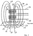
- FIG Fig. 3 A schematic representation of the generation of eddy currents is given in FIG Fig. 3 shown.
- An eddy current sensor is provided with two coils 24 and 26, which are brought close to the inside surface 27 of the pipeline wall and of which at least the coil 24 is designed as a transmitter coil.
- the coils 24, 26 are preferably arranged one above the other or one below the other, ie one behind the other in a direction perpendicular to the surface.
- a primary magnetic field, represented by field lines 28, is generated by the coils 24, 25 by means of an alternating current. Because of this time-varying magnetic field, in connection with the magnetic field generated by the magnetizing device, eddy currents are generated in the pipeline wall, which are shown here with dashed lines 29.
- the secondary magnetic field leads to an induction in the coils 24 and 26, which occurs via an in the Fig. 4 shown circuit measured can be.
- the coils 24 and 26 are connected to resistors 32 to form a bridge circuit, wherein a voltage can be tapped between the bridge points 33, which voltage can be amplified via an amplifier 34 and is fed to a phase-sensitive evaluation.
- the evaluation can preferably be performed according to the flow chart Fig. 5 take place, after which a frequency generator 36 drives the bridge circuit 37.
- the voltage tapped there is fed to a phase-sensitive detector 38 via an amplifier 34.
- the signal evaluated there can be phase-rotated (evaluation module 39) or further processed directly amplified via an amplifier 41.
- the signal can then be stored in a storage means 42, if necessary output, and evaluated in an evaluation unit 43 with regard to any changes.
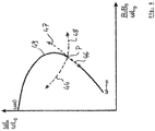
- the reactance is plotted on the ordinate and the ohmic resistance is plotted on the abscissa.
- the eddy current sensor measures a certain point in the impedance plane, which moves to another point in the plane when the sensor is on the test object. The influence of the test object can therefore be described as a change in the coil characteristics.
- the size and direction of the change in impedance depends here as described above on the material properties, in particular the electrical conductivity and magnetic permeability of the test object.
- the distance between the coil and the test object is also relevant.
- ⁇ L is the imaginary part of the measurement in the sample
- ⁇ L0 the imaginary part of the measurement in air
- R the real part of the measurement on the sample
- R0 the real part of the measurement in air.
- a change in the lift-off starting from a point P in the impedance plane leads to shifts in the direction of the arrow 44, changes in the conductivity s lead to a change along the arrow 46, permeability changes to changes in the direction of the arrow 47 and changes in wall thickness to changes according to the arrow 48.
- ⁇ is to be understood as the excitation frequency of the sensor device. Changes in wall thickness are perceived or excluded via changes in the magnetization of the wall by means of the HALL sensor; the magnetization in almost saturation prevents a change in the signal in direction 47, and lift-off in direction 44 is also excluded. so that the changes on the curve should only result from changes in conductivity.
- the eddy current signal is preferably recorded at a saturation magnetization of> 5 kA / m.
- Fig. 7 shows an example of a hysteresis curve for a steel that is often used in the pipeline sector. Magnetic flux densities from around 1.5 T can be sufficient in order not to significantly falsify the measurement result. With a few metals, even flux densities from 1.2 T can be sufficient.
- the values for the relative permeability in the range from 220 to 235, preferably from 225 to 233, in particular for the types of steel to be considered in the pipeline area.
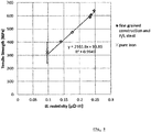
- arbitrary units] can be represented as a linear function of the specific electrical resistance. The same applies to the conductivity, which is reciprocal to the specific electrical resistance.
- the steel grades to be considered from the pipeline area have a high correlation with a correlation coefficient of 0.99 result.
- the dependence on mechanical-technological parameters, such as the one in Fig. 9 The tensile strength shown has been correlated with the specific resistance.
- the corresponding data on a large number of possible and used materials from the pipeline area are stored in a database, which then contains the reference data. Accordingly can the tensile strength can then be fitted directly against the eddy current signal ( Fig. 10 ).
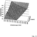
- a characteristic surface for the direct determination of the tensile strength from the two measured values of the eddy current signal and the magnetic field strength can be generated from this data ( Fig. 11 ).
- the sensor device as part of an inspection pig can be moved within a pipeline and along its inner metallic surface, there picks up eddy current signals, from these the electrical conductivity or the specific electrical resistance of the metal is determined and then from this variable the parameter of the metal is derived. This allows the materials of pipelines that were laid decades ago to be determined.
Landscapes
- Chemical & Material Sciences (AREA)
- Chemical Kinetics & Catalysis (AREA)
- Electrochemistry (AREA)
- Physics & Mathematics (AREA)
- Health & Medical Sciences (AREA)
- Life Sciences & Earth Sciences (AREA)
- Analytical Chemistry (AREA)
- Biochemistry (AREA)
- General Health & Medical Sciences (AREA)
- General Physics & Mathematics (AREA)
- Immunology (AREA)
- Pathology (AREA)
- Investigating Or Analyzing Materials By The Use Of Magnetic Means (AREA)
Claims (8)
- Procédé d'inspection de pipeline pour la détermination de caractéristiques mécano-technologiques d'aciers ferromagnétiques, selon lequel un dispositif de détection (11) en tant que partie d'un racleur d'inspection se déplace à l'intérieur d'un pipeline et le long de la surface (27) côté intérieur de celui-ci, dans lequel un dispositif de magnétisation présentant au moins un aimant permanent ou électroaimant (17) magnétise au moins sensiblement de manière saturée le métal à déterminer sous forme d'acier ferromagnétique pour la réduction au minimum de l'influence de la perméabilité relative et le dispositif de détection (11) comprenant une bobine émettrice (24) produit un champ magnétique alternatif, lequel coopère avec le champ magnétique produit par le dispositif de magnétisation dans le métal et produit un courant de Foucault, qui est mesuré par un capteur de courant de Foucault du dispositif de détection (11), dans lequel un capteur d'intensité de champ magnétique (12) mesure le champ magnétique du métal au moins à proximité de la surface et le dispositif de détection (11) pour une profondeur de pénétration du courant de Foucault inférieure à 1 mm utilise des fréquences de 100 kHz à 500 kHz, et dans lequel la conductivité électrique et/ou la résistance électrique spécifique du métal est déterminée au moyen d'un dispositif d'évaluation (43) à partir des données du capteur de courant de Foucault sur la base de données de référence d'une base de données de référence comprenant la dureté, la limite d'élasticité apparente ou la résistance à la traction ainsi que la conductivité électrique ou la résistance électrique d'aciers ferromagnétiques ainsi que la dureté, la limite d'élasticité apparente ou la résistance à la traction est déduite de la conductivité ou de la résistance en tant que caractéristique mécano-technologique du métal.
- Procédé selon la revendication 1, caractérisé en ce que plusieurs des dispositifs de détection (11) reçoivent dans la direction périphérique autour d'un axe longitudinal médian (9) du racleur d'inspection des données pour la détection de la caractéristique de la paroi de pipeline.
- Procédé selon l'une quelconque des revendications précédentes, caractérisé en ce que le champ magnétique pour la production du courant de Foucault est produit au moins par la première bobine bobine émettrice (24) du dispositif de détection (11), le dispositif de détection comprend encore une autre bobine (26) et le courant de Foucault est mesuré sur la base d'une différence de tension et de phase dans un montage en pont (37) comprenant les deux bobines (24, 26).
- Procédé selon l'une quelconque des revendications précédentes, caractérisé en ce qu'un champ magnétique dont l'intensité atteint plus de 4 kA/m est produit par le dispositif de magnétisation dans le métal.
- Procédé selon l'une quelconque des revendications précédentes, caractérisé en ce que la distance du capteur de courant de Foucault est enregistrée et/ou prédéfinie, afin de mettre hors circuit la dépendance du signal de courant de Foucault du décollement.
- Procédé selon l'une quelconque des revendications précédentes, caractérisé en ce que la température est mesurée par un capteur de température (15), afin de corriger la conductivité électrique ou la résistance électrique spécifique et/ou le signal de courant de Foucault en ce qui concerne la température.
- Procédé selon l'une quelconque des revendications précédentes, caractérisé en ce que le dispositif de détection (11) présente au moins deux, de préférence trois capteurs de courant de Foucault disposés en particulier sur un support de capteur (22) commun, qui mesurent le courant de Foucault à différentes fréquences.
- Procédé selon l'une quelconque des revendications précédentes, caractérisé en ce qu'une pluralité de dispositifs de détection (11) sont disposés dans la direction périphérique les uns à côté des autres et par rapport à un axe longitudinal médian (9) de manière mobile dans la direction radiale, de telle sorte que les dispositifs de détection (11) sont disposés sur la face intérieure d'un pipeline métallique et mesurent la grandeur caractéristique de celui-ci dans la direction périphérique.
Applications Claiming Priority (2)
| Application Number | Priority Date | Filing Date | Title |
|---|---|---|---|
| DE102013015566.5A DE102013015566A1 (de) | 2013-09-20 | 2013-09-20 | Verfahren zur berührungslosen Bestimmung einer mechanisch-technologischen Kenngröße von ferromagnetischen Metallen sowie Vorrichtung hierfür |
| PCT/EP2014/002490 WO2015039742A1 (fr) | 2013-09-20 | 2014-09-16 | Procédé de détermination sans contact d'une caractéristique technologique mécanique de métaux ferromagnétiques et dispositif correspondant |
Publications (2)
| Publication Number | Publication Date |
|---|---|
| EP3047264A1 EP3047264A1 (fr) | 2016-07-27 |
| EP3047264B1 true EP3047264B1 (fr) | 2022-01-05 |
Family
ID=51662040
Family Applications (1)
| Application Number | Title | Priority Date | Filing Date |
|---|---|---|---|
| EP14781058.4A Active EP3047264B1 (fr) | 2013-09-20 | 2014-09-16 | Procédé de détermination d'une caractéristique mécano-technologique d'un metal ferromagnétique |
Country Status (6)
| Country | Link |
|---|---|
| US (1) | US11604166B2 (fr) |
| EP (1) | EP3047264B1 (fr) |
| CA (1) | CA2924787C (fr) |
| DE (1) | DE102013015566A1 (fr) |
| ES (1) | ES2908446T3 (fr) |
| WO (1) | WO2015039742A1 (fr) |
Families Citing this family (7)
| Publication number | Priority date | Publication date | Assignee | Title |
|---|---|---|---|---|
| EP3382385B1 (fr) | 2015-11-16 | 2022-02-16 | National University Corporation Kobe University | Procédé d'observation et dispositif d'observation |
| US10444194B2 (en) | 2016-04-26 | 2019-10-15 | Quanta Associates, L.P. | Method and apparatus for material identification of pipelines and other tubulars |
| US10364665B2 (en) | 2016-07-19 | 2019-07-30 | Quanta Associates, L.P. | Method and apparatus for stress mapping of pipelines and other tubulars |
| RU2670194C1 (ru) * | 2018-02-02 | 2018-10-18 | Общество с ограниченной ответственностью "СТАЛЛ" | Способ электромагнитной дефектоскопии трубы и устройство для этого |
| AU2019318105B2 (en) * | 2018-08-08 | 2024-09-12 | Pure Technologies Ltd. | Method and apparatus to detect flaws in metallic pipe |
| CN114623681B (zh) * | 2020-12-14 | 2023-06-23 | 中冶长天国际工程有限责任公司 | 一种精准测量及调整燃料量控制回转窑内物料温度的方法 |
| CN114623682B (zh) * | 2020-12-14 | 2023-06-23 | 中冶长天国际工程有限责任公司 | 一种测量及调整风量和燃料量控制回转窑物料温度的方法 |
Citations (1)
| Publication number | Priority date | Publication date | Assignee | Title |
|---|---|---|---|---|
| DE102009009027A1 (de) * | 2009-02-16 | 2010-08-19 | Audi Ag | Verfahren und Vorrichtung zum Bestimmen einer Materialeigenschaft eines elektrisch leitfähigen Bauteils |
Family Cites Families (11)
| Publication number | Priority date | Publication date | Assignee | Title |
|---|---|---|---|---|
| US4855676A (en) * | 1987-05-06 | 1989-08-08 | Atomic Energy Of Canada Limited | Ferromagnetic eddy current probe having transmit and receive coil assemblies |
| FR2645964B1 (fr) * | 1989-04-18 | 1991-07-26 | Siderurgie Fse Inst Rech | Procede et dispositif de controle non destructif de materiau magnetique presentant un gradient de structure dans sa partie superficielle |
| US5006800A (en) * | 1989-11-06 | 1991-04-09 | General Electric Company | Eddy current imaging apparatus and method using phase difference detection |
| US6067846A (en) * | 1997-10-27 | 2000-05-30 | Hill; Jack O. | Apparatus and method for testing the hardness of a pipe |
| EP1377887B1 (fr) * | 2001-04-12 | 2006-05-31 | Micro-Epsilon Messtechnik GmbH & Co. KG | Configuration de circuit et procede permettant d'obtenir une compensation thermique |
| US6768298B2 (en) * | 2001-07-17 | 2004-07-27 | Transportation Technology Center, Inc. | Transverse crack detection in rail head using low frequency eddy currents |
| US6847207B1 (en) * | 2004-04-15 | 2005-01-25 | Tdw Delaware, Inc. | ID-OD discrimination sensor concept for a magnetic flux leakage inspection tool |
| US7355395B2 (en) * | 2004-10-06 | 2008-04-08 | Enerize Corporation | Method and apparatus for eddy current-based quality inspection of dry electrode structure |
| EP2294399B1 (fr) * | 2008-06-27 | 2019-08-21 | PII (Canada) Limited | Contrôle non destructif intégré multi-capteurs |
| GB2475315B (en) * | 2009-11-16 | 2014-07-16 | Innospection Group Ltd | Inspection apparatus and method |
| JP4905560B2 (ja) * | 2010-01-14 | 2012-03-28 | トヨタ自動車株式会社 | 渦流計測用センサ、及び、渦流計測用センサによる検査方法 |
-
2013
- 2013-09-20 DE DE102013015566.5A patent/DE102013015566A1/de not_active Withdrawn
-
2014
- 2014-09-16 EP EP14781058.4A patent/EP3047264B1/fr active Active
- 2014-09-16 ES ES14781058T patent/ES2908446T3/es active Active
- 2014-09-16 WO PCT/EP2014/002490 patent/WO2015039742A1/fr active Application Filing
- 2014-09-16 CA CA2924787A patent/CA2924787C/fr active Active
- 2014-09-16 US US15/023,104 patent/US11604166B2/en active Active
Patent Citations (1)
| Publication number | Priority date | Publication date | Assignee | Title |
|---|---|---|---|---|
| DE102009009027A1 (de) * | 2009-02-16 | 2010-08-19 | Audi Ag | Verfahren und Vorrichtung zum Bestimmen einer Materialeigenschaft eines elektrisch leitfähigen Bauteils |
Also Published As
| Publication number | Publication date |
|---|---|
| DE102013015566A1 (de) | 2015-03-26 |
| ES2908446T3 (es) | 2022-04-29 |
| CA2924787C (fr) | 2024-02-13 |
| US20160231277A1 (en) | 2016-08-11 |
| WO2015039742A1 (fr) | 2015-03-26 |
| EP3047264A1 (fr) | 2016-07-27 |
| CA2924787A1 (fr) | 2015-03-26 |
| US11604166B2 (en) | 2023-03-14 |
Similar Documents
| Publication | Publication Date | Title |
|---|---|---|
| EP3047264B1 (fr) | Procédé de détermination d'une caractéristique mécano-technologique d'un metal ferromagnétique | |
| DE3132808C2 (de) | "Vorrichtung zur zerstörungsfreien Prüfung ferromagnetischer Körper" | |
| DE3327762C2 (de) | Vorrichtung und Verfahren zum Messen der Wanddicke eines ferromagnetischen Elementes | |
| EP2893336B1 (fr) | Capteur différentiel, système d'analyse et procédé de détection de défaux dans des materiaux électriquement conducteurs | |
| EP1769239A1 (fr) | Procede et dispositif d'essai non destructif de tuyaux | |
| DE102011000917B4 (de) | Streuflusssonde zur zerstörungsfreien Streuflussprüfung von Körpern aus magnetisierbarem Werkstoff | |
| EP3074725B1 (fr) | Dispositif et procédé pour détecter une position d'une cible de position | |
| RU2542624C1 (ru) | Способ вихретокового контроля медной катанки и устройство для его реализации | |
| DE4126707A1 (de) | Wirbelstromsensor | |
| DE10026313A1 (de) | Magnetisches zerstörungsfreies Verfahren und Prüfvorrichtung zum Erfassen eines Metallflächenverlustes sowie lokalen Defekten in länglichen ferromagnetischen Gegenständen | |
| EP0831323A1 (fr) | Méthode pour le contrÔle non-destructif d'un objet avec un joint de soudure d'un matériau magnétisable | |
| DE102013209774B4 (de) | Prüfverfahren und Prüfvorrichtung zur Wirbelstromprüfung mit Vormagnetisierung | |
| DE102008059032B4 (de) | Verfahren und Vorrichtung zur Bestimmung ob eine Veränderung eines Substrats unter einer das Substrat bedeckenden Schicht vorliegt | |
| DE102013018114A1 (de) | Vorrichtung zur zerstörungsfreien Prüfung eines Prüfkörpers | |
| DE2530589A1 (de) | Verfahren und anordnung zur ueberwachung von rohrleitungen und dergleichen | |
| DE102018130090B4 (de) | Verfahren zur Bestimmung von Mikrostrukturvariationen in einer Probe und Analysevorrichtung | |
| EP2023131B1 (fr) | Procédé et dispositif destinés à la vérification sans destruction d'un objet contenant des parties de matériel magnétiques et électriques | |
| DE102004045271B4 (de) | Verfahren und Vorrichtung zur Detektion von Fehlstellen eines Prüfkörpers aus ferromagnetischem Material | |
| BE1028730B1 (de) | Verfahren zur Inspektion von Rohrleitungen und zugehörige Inspektionsvorrichtung | |
| DE102006013278A1 (de) | Verfahren und Vorrichtung zur thermografischen Detektion von Fehlstellen eines Prüfkörpers aus ferromagnetischem Material | |
| DE102017129150A1 (de) | Verfahren und Vorrichtung zur Messung der Dicke von nicht magnetisierbaren Schichten auf einem magnetisierbaren Grundwerkstoff | |
| EP3969891B1 (fr) | Procede et dispositif de controle inductif de pieces metalliques pour la detection d'anomalies proches de la surface | |
| EP0212324A2 (fr) | Procédé pour tester sans contact des objets électriquement conducteurs et appareil pour la mise en oeuvre de ce procédé | |
| EP3279653A1 (fr) | Dispositif et procede destines a la determination non destructive de la teneur de la partie magnetisable et/ou non magnetisable d'un echantillon | |
| WO2015140220A1 (fr) | Système de détection de champ magnétique |
Legal Events
| Date | Code | Title | Description |
|---|---|---|---|
| PUAI | Public reference made under article 153(3) epc to a published international application that has entered the european phase |
Free format text: ORIGINAL CODE: 0009012 |
|
| 17P | Request for examination filed |
Effective date: 20160420 |
|
| AK | Designated contracting states |
Kind code of ref document: A1 Designated state(s): AL AT BE BG CH CY CZ DE DK EE ES FI FR GB GR HR HU IE IS IT LI LT LU LV MC MK MT NL NO PL PT RO RS SE SI SK SM TR |
|
| AX | Request for extension of the european patent |
Extension state: BA ME |
|
| DAX | Request for extension of the european patent (deleted) | ||
| RIN1 | Information on inventor provided before grant (corrected) |
Inventor name: THALE, WERNER Inventor name: MOLENDA, DANIEL Inventor name: RAPP, MICHAEL Inventor name: REINING, BERNHARD |
|
| STAA | Information on the status of an ep patent application or granted ep patent |
Free format text: STATUS: EXAMINATION IS IN PROGRESS |
|
| 17Q | First examination report despatched |
Effective date: 20180507 |
|
| STAA | Information on the status of an ep patent application or granted ep patent |
Free format text: STATUS: EXAMINATION IS IN PROGRESS |
|
| GRAP | Despatch of communication of intention to grant a patent |
Free format text: ORIGINAL CODE: EPIDOSNIGR1 |
|
| STAA | Information on the status of an ep patent application or granted ep patent |
Free format text: STATUS: GRANT OF PATENT IS INTENDED |
|
| INTG | Intention to grant announced |
Effective date: 20210818 |
|
| GRAS | Grant fee paid |
Free format text: ORIGINAL CODE: EPIDOSNIGR3 |
|
| GRAA | (expected) grant |
Free format text: ORIGINAL CODE: 0009210 |
|
| STAA | Information on the status of an ep patent application or granted ep patent |
Free format text: STATUS: THE PATENT HAS BEEN GRANTED |
|
| AK | Designated contracting states |
Kind code of ref document: B1 Designated state(s): AL AT BE BG CH CY CZ DE DK EE ES FI FR GB GR HR HU IE IS IT LI LT LU LV MC MK MT NL NO PL PT RO RS SE SI SK SM TR |
|
| REG | Reference to a national code |
Ref country code: GB Ref legal event code: FG4D Free format text: NOT ENGLISH |
|
| REG | Reference to a national code |
Ref country code: CH Ref legal event code: EP |
|
| REG | Reference to a national code |
Ref country code: AT Ref legal event code: REF Ref document number: 1461024 Country of ref document: AT Kind code of ref document: T Effective date: 20220115 |
|
| REG | Reference to a national code |
Ref country code: DE Ref legal event code: R096 Ref document number: 502014016068 Country of ref document: DE |
|
| REG | Reference to a national code |
Ref country code: IE Ref legal event code: FG4D Free format text: LANGUAGE OF EP DOCUMENT: GERMAN |
|
| REG | Reference to a national code |
Ref country code: NL Ref legal event code: FP |
|
| REG | Reference to a national code |
Ref country code: LT Ref legal event code: MG9D |
|
| REG | Reference to a national code |
Ref country code: ES Ref legal event code: FG2A Ref document number: 2908446 Country of ref document: ES Kind code of ref document: T3 Effective date: 20220429 |
|
| REG | Reference to a national code |
Ref country code: NO Ref legal event code: T2 Effective date: 20220105 |
|
| PG25 | Lapsed in a contracting state [announced via postgrant information from national office to epo] |
Ref country code: SE Free format text: LAPSE BECAUSE OF FAILURE TO SUBMIT A TRANSLATION OF THE DESCRIPTION OR TO PAY THE FEE WITHIN THE PRESCRIBED TIME-LIMIT Effective date: 20220105 Ref country code: RS Free format text: LAPSE BECAUSE OF FAILURE TO SUBMIT A TRANSLATION OF THE DESCRIPTION OR TO PAY THE FEE WITHIN THE PRESCRIBED TIME-LIMIT Effective date: 20220105 Ref country code: PT Free format text: LAPSE BECAUSE OF FAILURE TO SUBMIT A TRANSLATION OF THE DESCRIPTION OR TO PAY THE FEE WITHIN THE PRESCRIBED TIME-LIMIT Effective date: 20220505 Ref country code: LT Free format text: LAPSE BECAUSE OF FAILURE TO SUBMIT A TRANSLATION OF THE DESCRIPTION OR TO PAY THE FEE WITHIN THE PRESCRIBED TIME-LIMIT Effective date: 20220105 Ref country code: HR Free format text: LAPSE BECAUSE OF FAILURE TO SUBMIT A TRANSLATION OF THE DESCRIPTION OR TO PAY THE FEE WITHIN THE PRESCRIBED TIME-LIMIT Effective date: 20220105 Ref country code: BG Free format text: LAPSE BECAUSE OF FAILURE TO SUBMIT A TRANSLATION OF THE DESCRIPTION OR TO PAY THE FEE WITHIN THE PRESCRIBED TIME-LIMIT Effective date: 20220405 |
|
| PG25 | Lapsed in a contracting state [announced via postgrant information from national office to epo] |
Ref country code: PL Free format text: LAPSE BECAUSE OF FAILURE TO SUBMIT A TRANSLATION OF THE DESCRIPTION OR TO PAY THE FEE WITHIN THE PRESCRIBED TIME-LIMIT Effective date: 20220105 Ref country code: LV Free format text: LAPSE BECAUSE OF FAILURE TO SUBMIT A TRANSLATION OF THE DESCRIPTION OR TO PAY THE FEE WITHIN THE PRESCRIBED TIME-LIMIT Effective date: 20220105 Ref country code: GR Free format text: LAPSE BECAUSE OF FAILURE TO SUBMIT A TRANSLATION OF THE DESCRIPTION OR TO PAY THE FEE WITHIN THE PRESCRIBED TIME-LIMIT Effective date: 20220406 Ref country code: FI Free format text: LAPSE BECAUSE OF FAILURE TO SUBMIT A TRANSLATION OF THE DESCRIPTION OR TO PAY THE FEE WITHIN THE PRESCRIBED TIME-LIMIT Effective date: 20220105 |
|
| PG25 | Lapsed in a contracting state [announced via postgrant information from national office to epo] |
Ref country code: IS Free format text: LAPSE BECAUSE OF FAILURE TO SUBMIT A TRANSLATION OF THE DESCRIPTION OR TO PAY THE FEE WITHIN THE PRESCRIBED TIME-LIMIT Effective date: 20220505 |
|
| REG | Reference to a national code |
Ref country code: DE Ref legal event code: R097 Ref document number: 502014016068 Country of ref document: DE |
|
| PG25 | Lapsed in a contracting state [announced via postgrant information from national office to epo] |
Ref country code: SM Free format text: LAPSE BECAUSE OF FAILURE TO SUBMIT A TRANSLATION OF THE DESCRIPTION OR TO PAY THE FEE WITHIN THE PRESCRIBED TIME-LIMIT Effective date: 20220105 Ref country code: SK Free format text: LAPSE BECAUSE OF FAILURE TO SUBMIT A TRANSLATION OF THE DESCRIPTION OR TO PAY THE FEE WITHIN THE PRESCRIBED TIME-LIMIT Effective date: 20220105 Ref country code: RO Free format text: LAPSE BECAUSE OF FAILURE TO SUBMIT A TRANSLATION OF THE DESCRIPTION OR TO PAY THE FEE WITHIN THE PRESCRIBED TIME-LIMIT Effective date: 20220105 Ref country code: EE Free format text: LAPSE BECAUSE OF FAILURE TO SUBMIT A TRANSLATION OF THE DESCRIPTION OR TO PAY THE FEE WITHIN THE PRESCRIBED TIME-LIMIT Effective date: 20220105 Ref country code: DK Free format text: LAPSE BECAUSE OF FAILURE TO SUBMIT A TRANSLATION OF THE DESCRIPTION OR TO PAY THE FEE WITHIN THE PRESCRIBED TIME-LIMIT Effective date: 20220105 Ref country code: CZ Free format text: LAPSE BECAUSE OF FAILURE TO SUBMIT A TRANSLATION OF THE DESCRIPTION OR TO PAY THE FEE WITHIN THE PRESCRIBED TIME-LIMIT Effective date: 20220105 |
|
| PLBE | No opposition filed within time limit |
Free format text: ORIGINAL CODE: 0009261 |
|
| STAA | Information on the status of an ep patent application or granted ep patent |
Free format text: STATUS: NO OPPOSITION FILED WITHIN TIME LIMIT |
|
| PG25 | Lapsed in a contracting state [announced via postgrant information from national office to epo] |
Ref country code: AL Free format text: LAPSE BECAUSE OF FAILURE TO SUBMIT A TRANSLATION OF THE DESCRIPTION OR TO PAY THE FEE WITHIN THE PRESCRIBED TIME-LIMIT Effective date: 20220105 |
|
| 26N | No opposition filed |
Effective date: 20221006 |
|
| PG25 | Lapsed in a contracting state [announced via postgrant information from national office to epo] |
Ref country code: SI Free format text: LAPSE BECAUSE OF FAILURE TO SUBMIT A TRANSLATION OF THE DESCRIPTION OR TO PAY THE FEE WITHIN THE PRESCRIBED TIME-LIMIT Effective date: 20220105 |
|
| PG25 | Lapsed in a contracting state [announced via postgrant information from national office to epo] |
Ref country code: MC Free format text: LAPSE BECAUSE OF FAILURE TO SUBMIT A TRANSLATION OF THE DESCRIPTION OR TO PAY THE FEE WITHIN THE PRESCRIBED TIME-LIMIT Effective date: 20220105 |
|
| REG | Reference to a national code |
Ref country code: CH Ref legal event code: PL |
|
| REG | Reference to a national code |
Ref country code: BE Ref legal event code: MM Effective date: 20220930 |
|
| PG25 | Lapsed in a contracting state [announced via postgrant information from national office to epo] |
Ref country code: LU Free format text: LAPSE BECAUSE OF NON-PAYMENT OF DUE FEES Effective date: 20220916 |
|
| PG25 | Lapsed in a contracting state [announced via postgrant information from national office to epo] |
Ref country code: LI Free format text: LAPSE BECAUSE OF NON-PAYMENT OF DUE FEES Effective date: 20220930 Ref country code: IE Free format text: LAPSE BECAUSE OF NON-PAYMENT OF DUE FEES Effective date: 20220916 Ref country code: CH Free format text: LAPSE BECAUSE OF NON-PAYMENT OF DUE FEES Effective date: 20220930 |
|
| PG25 | Lapsed in a contracting state [announced via postgrant information from national office to epo] |
Ref country code: BE Free format text: LAPSE BECAUSE OF NON-PAYMENT OF DUE FEES Effective date: 20220930 |
|
| REG | Reference to a national code |
Ref country code: DE Ref legal event code: R081 Ref document number: 502014016068 Country of ref document: DE Owner name: ROSEN IP AG, CH Free format text: FORMER OWNER: ROSEN SWISS AG, STANS, CH |
|
| PGFP | Annual fee paid to national office [announced via postgrant information from national office to epo] |
Ref country code: NO Payment date: 20230919 Year of fee payment: 10 Ref country code: NL Payment date: 20230920 Year of fee payment: 10 Ref country code: GB Payment date: 20230921 Year of fee payment: 10 |
|
| REG | Reference to a national code |
Ref country code: AT Ref legal event code: MM01 Ref document number: 1461024 Country of ref document: AT Kind code of ref document: T Effective date: 20220916 |
|
| PGFP | Annual fee paid to national office [announced via postgrant information from national office to epo] |
Ref country code: FR Payment date: 20230918 Year of fee payment: 10 Ref country code: DE Payment date: 20230919 Year of fee payment: 10 |
|
| REG | Reference to a national code |
Ref country code: NO Ref legal event code: CHAD Owner name: ROSEN IP AG, CH |
|
| REG | Reference to a national code |
Ref country code: GB Ref legal event code: 732E Free format text: REGISTERED BETWEEN 20231207 AND 20231213 |
|
| PGFP | Annual fee paid to national office [announced via postgrant information from national office to epo] |
Ref country code: ES Payment date: 20231019 Year of fee payment: 10 |
|
| PG25 | Lapsed in a contracting state [announced via postgrant information from national office to epo] |
Ref country code: AT Free format text: LAPSE BECAUSE OF NON-PAYMENT OF DUE FEES Effective date: 20220916 |
|
| PGFP | Annual fee paid to national office [announced via postgrant information from national office to epo] |
Ref country code: IT Payment date: 20230929 Year of fee payment: 10 |
|
| PG25 | Lapsed in a contracting state [announced via postgrant information from national office to epo] |
Ref country code: HU Free format text: LAPSE BECAUSE OF FAILURE TO SUBMIT A TRANSLATION OF THE DESCRIPTION OR TO PAY THE FEE WITHIN THE PRESCRIBED TIME-LIMIT; INVALID AB INITIO Effective date: 20140916 |
|
| PG25 | Lapsed in a contracting state [announced via postgrant information from national office to epo] |
Ref country code: CY Free format text: LAPSE BECAUSE OF FAILURE TO SUBMIT A TRANSLATION OF THE DESCRIPTION OR TO PAY THE FEE WITHIN THE PRESCRIBED TIME-LIMIT Effective date: 20220105 |
|
| PG25 | Lapsed in a contracting state [announced via postgrant information from national office to epo] |
Ref country code: MK Free format text: LAPSE BECAUSE OF FAILURE TO SUBMIT A TRANSLATION OF THE DESCRIPTION OR TO PAY THE FEE WITHIN THE PRESCRIBED TIME-LIMIT Effective date: 20220105 |
|
| PG25 | Lapsed in a contracting state [announced via postgrant information from national office to epo] |
Ref country code: TR Free format text: LAPSE BECAUSE OF FAILURE TO SUBMIT A TRANSLATION OF THE DESCRIPTION OR TO PAY THE FEE WITHIN THE PRESCRIBED TIME-LIMIT Effective date: 20220105 |
|
| REG | Reference to a national code |
Ref country code: NL Ref legal event code: PD Owner name: ROSEN IP AG; CH Free format text: DETAILS ASSIGNMENT: CHANGE OF OWNER(S), ASSIGNMENT; FORMER OWNER NAME: ROSEN SWISS AG Effective date: 20240815 |