EP3046511B1 - Verfahren und vorrichtung zum komprimieren / laden von stentklappen - Google Patents
Verfahren und vorrichtung zum komprimieren / laden von stentklappen Download PDFInfo
- Publication number
- EP3046511B1 EP3046511B1 EP14766978.2A EP14766978A EP3046511B1 EP 3046511 B1 EP3046511 B1 EP 3046511B1 EP 14766978 A EP14766978 A EP 14766978A EP 3046511 B1 EP3046511 B1 EP 3046511B1
- Authority
- EP
- European Patent Office
- Prior art keywords
- stent
- valve
- compressor stage
- channel
- compressing
- Prior art date
- Legal status (The legal status is an assumption and is not a legal conclusion. Google has not performed a legal analysis and makes no representation as to the accuracy of the status listed.)
- Active
Links
- 238000000034 method Methods 0.000 title claims description 18
- 230000004044 response Effects 0.000 claims description 16
- 230000000747 cardiac effect Effects 0.000 claims description 7
- 238000007906 compression Methods 0.000 description 26
- 230000006835 compression Effects 0.000 description 24
- 238000004873 anchoring Methods 0.000 description 10
- 229920003023 plastic Polymers 0.000 description 10
- 239000004033 plastic Substances 0.000 description 9
- 239000000463 material Substances 0.000 description 7
- 230000008901 benefit Effects 0.000 description 6
- 238000002513 implantation Methods 0.000 description 6
- 230000006870 function Effects 0.000 description 5
- 229910052751 metal Inorganic materials 0.000 description 5
- 239000002184 metal Substances 0.000 description 5
- 210000003484 anatomy Anatomy 0.000 description 4
- 230000002441 reversible effect Effects 0.000 description 4
- 238000002788 crimping Methods 0.000 description 3
- 230000002452 interceptive effect Effects 0.000 description 3
- 230000000670 limiting effect Effects 0.000 description 3
- 230000006641 stabilisation Effects 0.000 description 3
- 238000011105 stabilization Methods 0.000 description 3
- 229920002614 Polyether block amide Polymers 0.000 description 2
- 229910045601 alloy Inorganic materials 0.000 description 2
- 239000000956 alloy Substances 0.000 description 2
- 230000004323 axial length Effects 0.000 description 2
- 239000000919 ceramic Substances 0.000 description 2
- 230000000295 complement effect Effects 0.000 description 2
- 230000008878 coupling Effects 0.000 description 2
- 238000010168 coupling process Methods 0.000 description 2
- 238000005859 coupling reaction Methods 0.000 description 2
- 238000006073 displacement reaction Methods 0.000 description 2
- 238000003780 insertion Methods 0.000 description 2
- 230000037431 insertion Effects 0.000 description 2
- HLXZNVUGXRDIFK-UHFFFAOYSA-N nickel titanium Chemical compound [Ti].[Ti].[Ti].[Ti].[Ti].[Ti].[Ti].[Ti].[Ti].[Ti].[Ti].[Ni].[Ni].[Ni].[Ni].[Ni].[Ni].[Ni].[Ni].[Ni].[Ni].[Ni].[Ni].[Ni].[Ni] HLXZNVUGXRDIFK-UHFFFAOYSA-N 0.000 description 2
- 229910001000 nickel titanium Inorganic materials 0.000 description 2
- 230000008569 process Effects 0.000 description 2
- 238000013519 translation Methods 0.000 description 2
- 239000012780 transparent material Substances 0.000 description 2
- 0 *C1*C#CC1 Chemical compound *C1*C#CC1 0.000 description 1
- 241000283690 Bos taurus Species 0.000 description 1
- MWCLLHOVUTZFKS-UHFFFAOYSA-N Methyl cyanoacrylate Chemical compound COC(=O)C(=C)C#N MWCLLHOVUTZFKS-UHFFFAOYSA-N 0.000 description 1
- WAIPAZQMEIHHTJ-UHFFFAOYSA-N [Cr].[Co] Chemical class [Cr].[Co] WAIPAZQMEIHHTJ-UHFFFAOYSA-N 0.000 description 1
- 238000005299 abrasion Methods 0.000 description 1
- 210000001765 aortic valve Anatomy 0.000 description 1
- 238000005452 bending Methods 0.000 description 1
- 230000001413 cellular effect Effects 0.000 description 1
- 230000008859 change Effects 0.000 description 1
- 239000011248 coating agent Substances 0.000 description 1
- 238000000576 coating method Methods 0.000 description 1
- 210000001105 femoral artery Anatomy 0.000 description 1
- 230000002209 hydrophobic effect Effects 0.000 description 1
- 239000007943 implant Substances 0.000 description 1
- 238000002955 isolation Methods 0.000 description 1
- 230000007246 mechanism Effects 0.000 description 1
- 238000012986 modification Methods 0.000 description 1
- 230000004048 modification Effects 0.000 description 1
- 238000000465 moulding Methods 0.000 description 1
- 230000036961 partial effect Effects 0.000 description 1
- 210000003516 pericardium Anatomy 0.000 description 1
- 230000002093 peripheral effect Effects 0.000 description 1
- 229920001296 polysiloxane Polymers 0.000 description 1
- 230000002829 reductive effect Effects 0.000 description 1
- 230000002040 relaxant effect Effects 0.000 description 1
- 239000010935 stainless steel Substances 0.000 description 1
- 229910001220 stainless steel Inorganic materials 0.000 description 1
- 229920002994 synthetic fiber Polymers 0.000 description 1
- 210000001519 tissue Anatomy 0.000 description 1
Images


Classifications
-
- A—HUMAN NECESSITIES
- A61—MEDICAL OR VETERINARY SCIENCE; HYGIENE
- A61F—FILTERS IMPLANTABLE INTO BLOOD VESSELS; PROSTHESES; DEVICES PROVIDING PATENCY TO, OR PREVENTING COLLAPSING OF, TUBULAR STRUCTURES OF THE BODY, e.g. STENTS; ORTHOPAEDIC, NURSING OR CONTRACEPTIVE DEVICES; FOMENTATION; TREATMENT OR PROTECTION OF EYES OR EARS; BANDAGES, DRESSINGS OR ABSORBENT PADS; FIRST-AID KITS
- A61F2/00—Filters implantable into blood vessels; Prostheses, i.e. artificial substitutes or replacements for parts of the body; Appliances for connecting them with the body; Devices providing patency to, or preventing collapsing of, tubular structures of the body, e.g. stents
- A61F2/02—Prostheses implantable into the body
- A61F2/24—Heart valves ; Vascular valves, e.g. venous valves; Heart implants, e.g. passive devices for improving the function of the native valve or the heart muscle; Transmyocardial revascularisation [TMR] devices; Valves implantable in the body
- A61F2/2427—Devices for manipulating or deploying heart valves during implantation
- A61F2/2436—Deployment by retracting a sheath
-
- A—HUMAN NECESSITIES
- A61—MEDICAL OR VETERINARY SCIENCE; HYGIENE
- A61F—FILTERS IMPLANTABLE INTO BLOOD VESSELS; PROSTHESES; DEVICES PROVIDING PATENCY TO, OR PREVENTING COLLAPSING OF, TUBULAR STRUCTURES OF THE BODY, e.g. STENTS; ORTHOPAEDIC, NURSING OR CONTRACEPTIVE DEVICES; FOMENTATION; TREATMENT OR PROTECTION OF EYES OR EARS; BANDAGES, DRESSINGS OR ABSORBENT PADS; FIRST-AID KITS
- A61F2/00—Filters implantable into blood vessels; Prostheses, i.e. artificial substitutes or replacements for parts of the body; Appliances for connecting them with the body; Devices providing patency to, or preventing collapsing of, tubular structures of the body, e.g. stents
- A61F2/95—Instruments specially adapted for placement or removal of stents or stent-grafts
- A61F2/9522—Means for mounting a stent or stent-graft onto or into a placement instrument
-
- A—HUMAN NECESSITIES
- A61—MEDICAL OR VETERINARY SCIENCE; HYGIENE
- A61F—FILTERS IMPLANTABLE INTO BLOOD VESSELS; PROSTHESES; DEVICES PROVIDING PATENCY TO, OR PREVENTING COLLAPSING OF, TUBULAR STRUCTURES OF THE BODY, e.g. STENTS; ORTHOPAEDIC, NURSING OR CONTRACEPTIVE DEVICES; FOMENTATION; TREATMENT OR PROTECTION OF EYES OR EARS; BANDAGES, DRESSINGS OR ABSORBENT PADS; FIRST-AID KITS
- A61F2/00—Filters implantable into blood vessels; Prostheses, i.e. artificial substitutes or replacements for parts of the body; Appliances for connecting them with the body; Devices providing patency to, or preventing collapsing of, tubular structures of the body, e.g. stents
- A61F2/02—Prostheses implantable into the body
- A61F2/24—Heart valves ; Vascular valves, e.g. venous valves; Heart implants, e.g. passive devices for improving the function of the native valve or the heart muscle; Transmyocardial revascularisation [TMR] devices; Valves implantable in the body
- A61F2/2412—Heart valves ; Vascular valves, e.g. venous valves; Heart implants, e.g. passive devices for improving the function of the native valve or the heart muscle; Transmyocardial revascularisation [TMR] devices; Valves implantable in the body with soft flexible valve members, e.g. tissue valves shaped like natural valves
- A61F2/2418—Scaffolds therefor, e.g. support stents
-
- A—HUMAN NECESSITIES
- A61—MEDICAL OR VETERINARY SCIENCE; HYGIENE
- A61F—FILTERS IMPLANTABLE INTO BLOOD VESSELS; PROSTHESES; DEVICES PROVIDING PATENCY TO, OR PREVENTING COLLAPSING OF, TUBULAR STRUCTURES OF THE BODY, e.g. STENTS; ORTHOPAEDIC, NURSING OR CONTRACEPTIVE DEVICES; FOMENTATION; TREATMENT OR PROTECTION OF EYES OR EARS; BANDAGES, DRESSINGS OR ABSORBENT PADS; FIRST-AID KITS
- A61F2/00—Filters implantable into blood vessels; Prostheses, i.e. artificial substitutes or replacements for parts of the body; Appliances for connecting them with the body; Devices providing patency to, or preventing collapsing of, tubular structures of the body, e.g. stents
- A61F2/95—Instruments specially adapted for placement or removal of stents or stent-grafts
- A61F2/962—Instruments specially adapted for placement or removal of stents or stent-grafts having an outer sleeve
- A61F2/97—Instruments specially adapted for placement or removal of stents or stent-grafts having an outer sleeve the outer sleeve being splittable
-
- A—HUMAN NECESSITIES
- A61—MEDICAL OR VETERINARY SCIENCE; HYGIENE
- A61F—FILTERS IMPLANTABLE INTO BLOOD VESSELS; PROSTHESES; DEVICES PROVIDING PATENCY TO, OR PREVENTING COLLAPSING OF, TUBULAR STRUCTURES OF THE BODY, e.g. STENTS; ORTHOPAEDIC, NURSING OR CONTRACEPTIVE DEVICES; FOMENTATION; TREATMENT OR PROTECTION OF EYES OR EARS; BANDAGES, DRESSINGS OR ABSORBENT PADS; FIRST-AID KITS
- A61F2220/00—Fixations or connections for prostheses classified in groups A61F2/00 - A61F2/26 or A61F2/82 or A61F9/00 or A61F11/00 or subgroups thereof
- A61F2220/0008—Fixation appliances for connecting prostheses to the body
-
- A—HUMAN NECESSITIES
- A61—MEDICAL OR VETERINARY SCIENCE; HYGIENE
- A61F—FILTERS IMPLANTABLE INTO BLOOD VESSELS; PROSTHESES; DEVICES PROVIDING PATENCY TO, OR PREVENTING COLLAPSING OF, TUBULAR STRUCTURES OF THE BODY, e.g. STENTS; ORTHOPAEDIC, NURSING OR CONTRACEPTIVE DEVICES; FOMENTATION; TREATMENT OR PROTECTION OF EYES OR EARS; BANDAGES, DRESSINGS OR ABSORBENT PADS; FIRST-AID KITS
- A61F2230/00—Geometry of prostheses classified in groups A61F2/00 - A61F2/26 or A61F2/82 or A61F9/00 or A61F11/00 or subgroups thereof
- A61F2230/0002—Two-dimensional shapes, e.g. cross-sections
- A61F2230/0028—Shapes in the form of latin or greek characters
- A61F2230/0054—V-shaped
-
- A—HUMAN NECESSITIES
- A61—MEDICAL OR VETERINARY SCIENCE; HYGIENE
- A61F—FILTERS IMPLANTABLE INTO BLOOD VESSELS; PROSTHESES; DEVICES PROVIDING PATENCY TO, OR PREVENTING COLLAPSING OF, TUBULAR STRUCTURES OF THE BODY, e.g. STENTS; ORTHOPAEDIC, NURSING OR CONTRACEPTIVE DEVICES; FOMENTATION; TREATMENT OR PROTECTION OF EYES OR EARS; BANDAGES, DRESSINGS OR ABSORBENT PADS; FIRST-AID KITS
- A61F2250/00—Special features of prostheses classified in groups A61F2/00 - A61F2/26 or A61F2/82 or A61F9/00 or A61F11/00 or subgroups thereof
- A61F2250/0014—Special features of prostheses classified in groups A61F2/00 - A61F2/26 or A61F2/82 or A61F9/00 or A61F11/00 or subgroups thereof having different values of a given property or geometrical feature, e.g. mechanical property or material property, at different locations within the same prosthesis
- A61F2250/0018—Special features of prostheses classified in groups A61F2/00 - A61F2/26 or A61F2/82 or A61F9/00 or A61F11/00 or subgroups thereof having different values of a given property or geometrical feature, e.g. mechanical property or material property, at different locations within the same prosthesis differing in elasticity, stiffness or compressibility
-
- A—HUMAN NECESSITIES
- A61—MEDICAL OR VETERINARY SCIENCE; HYGIENE
- A61F—FILTERS IMPLANTABLE INTO BLOOD VESSELS; PROSTHESES; DEVICES PROVIDING PATENCY TO, OR PREVENTING COLLAPSING OF, TUBULAR STRUCTURES OF THE BODY, e.g. STENTS; ORTHOPAEDIC, NURSING OR CONTRACEPTIVE DEVICES; FOMENTATION; TREATMENT OR PROTECTION OF EYES OR EARS; BANDAGES, DRESSINGS OR ABSORBENT PADS; FIRST-AID KITS
- A61F2250/00—Special features of prostheses classified in groups A61F2/00 - A61F2/26 or A61F2/82 or A61F9/00 or A61F11/00 or subgroups thereof
- A61F2250/0058—Additional features; Implant or prostheses properties not otherwise provided for
- A61F2250/0091—Additional features; Implant or prostheses properties not otherwise provided for transparent or translucent
Definitions
- the present invention relates to the field of stents for transcatheter delivery, and in particular to a method and apparatus for compressing a stent to a compressed condition and/or for loading a stent for a delivery catheter.
- the stent is a stent-valve, for example a cardiac stent-valve.
- the invention has been devised while addressing problems encountered with stent-valves, but the invention may also be applicable for compressing other types of stents for transcatheter delivery.
- WO-A-2012/038550 describes a cardiac stent-valve and a system for delivering the stent-valve percutaneously.
- the stent-valve is compressible to a compressed state suitable to be accommodated within two complementary sheaths at the delivery tip of the delivery catheter. In the compressed state, the small size enables the catheter to be introduced percutaneously, and advanced via the femoral artery, to reach the heart.
- the two sheaths cover different sections of the stent-valve, and are translatable in opposite directions to deploy the sections of the stent-valve in a predetermined sequence. Upon deployment, the stent-valve expands to an operative size.
- WO-A-2012/116368 describes a loading cone for loading a prosthetic valve into a sheath of a catheter.
- the task of compressing the stent-valve on to (or ready for) the delivery catheter is complicated because the stent-valve is delicate and vulnerable to damage. Damage may result from over compression, or a nonuniform stress distribution, or buckling, or non-circularity during compression, or from tearing or abrasion of valve component tissue. A deformed or damaged stent-valve may function imperfectly, or have a reduced operational life, or may be difficult or even impossible to implant correctly.
- a self-expanding stent-valve may also have more of a tendency to deform undesirably to a non-circular shape unless the shape is carefully controlled during compression. Further complications arise when the stent-valve is to be compressed for loading on to a delivery catheter having multiple sheaths that close over the stent-valve in different directions. Such sheaths limit the available room and possibilities for compressing the stent-valve.
- the present invention has been devised bearing the above issues in mind. It may be a non-limiting object to address and/or alleviate at least one of the above issues.
- a further aspect of the invention provides an apparatus for use in compressing a stent (preferably a stent-valve) for loading into a delivery catheter, the apparatus comprising a first compressor stage for compressing the stent; and a second compressor stage coupled or couplable to the first compressor stage and configured to further compress a portion of the stent after passing through the first compressor stage.
- a stent preferably a stent-valve
- the first compressor stage may comprise a hollow channel (which may optionally additionally or alternatively be referred to as a hollow channel member or hollow channel body), and the first compressor stage may be configured for progressively compressing the stent in response to, or in association with, longitudinal advancement of the stent within the hollow channel.
- a hollow channel which may optionally additionally or alternatively be referred to as a hollow channel member or hollow channel body
- the first compressor stage may be configured for progressively compressing the stent in response to, or in association with, longitudinal advancement of the stent within the hollow channel.
- the second compressor stage may be configured to compress a portion of the stent at the second compressor stage without advancement of the stent within the second compressor stage, for example, when the stent is substantially stationary (e.g. at least in the longitudinal direction).
- the stent may be advanced in incremental steps through the apparatus. While the stent is being advanced, the first compressor stage progressively compresses the stent in response to (or in association with) advancement within the hollow channel. Once advancement of the stent is stopped, the second compressor stage can be operated to further compress a portion of the stent thereat, for example temporarily to facilitate sliding (stepwise) a constraining sheath over or towards the further compressed portion. Thereafter, the second compressor stage may be released (or relaxed), and the stent advanced a further step longitudinally, and the process repeated stepwise.
- first compressor stage can provide controlled compression of the stent without excess loads
- second compressor stage can provide (optionally temporary) additional local crimping at a position on the stent to facilitate sliding a relatively tightly fitting constraining sheath (e.g. of the delivery catheter) over the compressed stent.
- the second compressor stage may be coupled (or couplable) to be at an exit (or exit end) of the first compressor stage.
- the second compressor stage may be releasably couplable to the first compressor stage, for example, by a screw threaded coupling.
- the first compressor stage may include a first manually operable actuator (e.g. first driver). Operation of the first actuator may advance the stent within the hollow channel, and compress the stent.
- a first manually operable actuator e.g. first driver
- the second compressor stage may include a second manually operable actuator (e.g. second driver). Operation of the second actuator may further compress a portion of the stent without advancing the stent with respect to the hollow channel.
- a second manually operable actuator e.g. second driver
- the first actuator and/or the second actuator may be rotatable. When both actuators are rotatable, they may optionally be rotatable about a common rotation axis (e.g., the longitudinal axis of the hollow channel).
- first and second compressor stages are envisaged for the first and second compressor stages, and any of the features below for each may be selected and combined as desired. All such selections are combinations are specifically envisaged herein.
- the second compressor stage may optionally include any one or more of the following:
- the first compressor stage may optionally include any one or more of the following:
- the apparatus may optionally further comprise at least one loading tube (which may optionally additionally or alternatively be referred to as a channel extension or an exit extension) for or usable at the exit and/or narrow (e.g. internally narrower) end of the first and/or second compressor stage.
- the loading tube may be removably attachable to the channel, or it may be associated with the channel by holding in place by hand, or it may be insertable into the exit of the channel.
- the extension is separated (e.g. removed) from the channel, this may permit the end of the stent to be observed at the exit/narrow end of the channel for loading onto, or engagement with, a delivery catheter.
- the extension may be placed, inserted or re-placed (e.g. attached or reattached) with respect to the channel.
- the loading tube has a bore therein.
- the bore may have substantially the same diameter as the exit end of the channel.
- the bore and/or the outer diameter of the loading tube may be slightly smaller than the diameter at the exit of the channel.
- the loading tube may be attachable by a fixing that withstands longitudinal load between the channel and the extension.
- the fixing may be a screw threaded fixing.
- the loading tube may be insertable at least partly into the channel at or through the exit.
- the invention provides loading tube apparatus for use in compressing and/or loading a stent (preferably a stent-valve) for a delivery catheter, the loading tube apparatus comprising:
- Such an apparatus can enable a loading tube to be fitted on to a delivery catheter, the loading tube having a smaller inner diameter than can or could otherwise easily be slid onto the delivery catheter.
- the plurality of segments may be placed and assembled at the desired position on the delivery catheter to define a tubular shape, and secured in the assembled shape by the retainer.
- the retainer may comprise at least one threaded nut, and/or a supporting overtube.
- the nut and/or overtube may have an inner diameter sufficiently large to be slid on to the delivery catheter.
- the loading tube apparatus as aforesaid may optionally be used in combination with the previously described (multi-compressor stage) compressing apparatus.
- the two may be especially useful when loading a stent on to a multiple-sheath delivery system in which the multiple sheaths close over respective portions of the stent from opposite first and second directions.
- the compressor apparatus may be suitable for compressing/loading a first portion of the stent into a first of the sheaths.
- the loading tube apparatus may be suitable for loading a second portion of the stent into a second of the sheaths.
- the two apparatus may be used one after the other, or both at the same time.
- the invention provides a method of loading a stent (preferably a stent-valve) on to a delivery catheter, the method comprising:
- the invention provides a method of loading a stent (preferably a stent-valve) on to a multiple-sheath delivery catheter, the catheter having first and second sheaths that close over respective portions of the stent-valve from opposite directions, the method comprising:
- the compressor apparatus may further comprise a second compressor stage, and the method may further comprise between steps (b) and (c) a further step of operating the second compressor stage without advancing the stent, to further compress locally a portion of the stent-valve to facilitate closing the first sheath in step (c). This additional step may be repeated in sequence as part of step (d).
- the method may further comprise a step of sliding an intermediate loading tube over the stent at least between steps (d) and (f) to facilitate the method.
- the invention provides apparatus for compressing a transcatheter cardiac stent-valve comprising: a first compressor stage including a hollow channel with a tapered interior surface configured for compressing a stent-valve in response to longitudinal advancement of the stent-valve within the channel; and a second compressor stage comprising a crimper for compressing a portion of the stent-valve without longitudinal advancement.
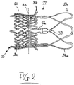
- Figs. 1 and 2 illustrate an example stent in the form of a stent-valve 10.
- the stent-valve 10 may be a cardiac stent-valve, for example an aortic stent-valve.
- the stent-valve 10 may be configured for transcatheter implantation in the body, for example enabling the use of minimally invasive techniques.
- the stent-valve 10 may be configured for transcatheter aortic valve implantation ("TAVI").
- TAVI transcatheter aortic valve implantation
- the stent-valve 10 may be transformable between an expanded state (as illustrated in Fig. 1 ), and a compressed state indicated by the broken line 10'.
- the expanded state may correspond approximately to an operative state of the stent-valve after implantation.
- the stent-valve 10 may not fully achieve the expanded state at implantation, tolerance being allowed for size mismatching and/or for slight compression to maintain an outward resilient bias for a friction fit in the native anatomy.
- the compressed state 10' may correspond to a delivery state to be accommodated by a delivery catheter 12 and/or for introduction into the anatomy to the desired implantation site.
- the stent-valve 10 may be of a self-expanding type that is resiliently biased towards the expanded state, and is compressible to the compressed state 10' by application of suitable radial compression forces.
- the stent-valve 10 remains in its compressed state while constrained. When the constraint is removed, the stent-valve 10 self expands towards the expanded state.
- the stent-valve 10 may be of a non-self-expanding type that requires application of an expansion force to transform the stent-valve 10 from the compressed state 10' to the expanded state.
- the stent-valve 10 may comprise a stent component 14 and a valve component 16.
- the stent component 14 may provide an anchoring function for anchoring the stent-valve in the native anatomy and/or a support function for supporting the valve component 16.
- the stent component 14 may be of any suitable material or materials.
- the stent component 14 may be of metal.
- Example materials include shape memory and/or superelastic alloys (for example, nitinol), stainless steel, or cobalt-chromium alloy.
- the stent component 14 is self-expanding and is of shape memory/superelastic alloy (e.g. nitinol). However, the stent component 14 could also be substantially non-self expanding.
- the stent component 14 may have any profile desired for anchoring and/or aligning the stent-valve 10 with respect to the native anatomy at the desired implantation site.
- the stent component 14 may be generally cylindrical in shape, or comprise one more generally cylindrical portions or portions lying on a generally cylindrical surface (e.g. 20c and 22a). Additionally or alternatively, the stent component 14 may be generally non-cylindrical in shape or comprise one or more generally non-cylindrical portions or portions lying on a non-cylindrical surface (e.g. 20a, 20b, and 24). Additionally or alternatively, the stent component 14 may comprise one or more anchor projections, and/or one or more stabilization portions.
- the stent component 14 optionally comprises an anchoring portion 20 defined, for example, by an inferior crown 20a and a superior crown 20b that define a groove and/or waist 20c therebetween.
- the anchoring portion 20 may have a first resistance to compression, and may comprise a cellular lattice.
- the stent component 14 optionally (further) comprises a valve support portion 22 comprising, for example, a plurality (e.g. three) commissural support posts 22a.
- the commissural support posts 22a may be arranged on a pitch circle diameter smaller than an extremity of at least one of the crowns 20a and 20b.
- the commissural support posts 22a may be arranged on a pitch circle diameter corresponding to the waist 20c.
- the commissural support posts 22a may partly overlap at least one of the crowns 20 and 22 in the axial direction, and extend axially beyond that respective crown.
- the commissural support posts 22a may be frame-like.
- the commissural support posts 22a may have a shape that follows, at least approximately, a peripheral contour of the valve, at least in the region of the valve periphery adjacent to the commissural support posts.
- the stent component 14 optionally (further) comprises a stabilization or alignment portion 24 defined, for example, by a plurality (e.g. three) wings or arches 24a.
- the arches 24a may extend from tips of the commissural support posts 22a, to define a vaulted structure thereover.
- the alignment portion 24 may have a greater flexibility than the anchoring portion 20 and/or the valve support function 22.
- the alignment portion 24 may have a second resistance to compression that is smaller than the first resistance to compression of the anchoring portion 20.
- the alignment portion 24 may be less rigid (e.g. radially) than the anchoring portion 20 and/or the valve support portion 22.
- the stent component 14 optionally (further) comprises an attachment portion 26 for attaching the stent component 14 to a stent receiver 28 of the delivery catheter 12.
- the stent receiver 28 may be a stent holder and will be referred to as such hereinafter, although other types of receiver for receiving and/or accommodating at least a portion of the stent-valve 10 may be used as desired.
- the attachment portion 26 may comprise one or more geometrical openings, or one or more lugs or other projections, for forming an interference (e.g. interlocking) fit with a complementary portion of the stent holder 28.
- the attachment portion 26 may be arranged at or adjacent to at least one extreme end of the stent component 14. In the present embodiment, the attachment portion 26 is defined by a plurality (e.g. three) of extensions of cells of the inferior crown 20a.
- the valve component 16 may be of any suitable natural and/or synthetic material(s).
- the valve component 16 may comprise porcine and/or bovine pericardium and/or harvested natural valve material.
- the valve component 16 may comprise a plurality of leaflets arranged to coapt or collapse to a closed position to obstruct flow in one direction therepast, while flexing apart to an open position to allow flow in an opposite direction.
- the valve component 16 may be accommodated at the valve support portion 22 and/or at least partly within the anchoring portion 20.
- the stent-valve 10 e.g. the valve component 16
- the skirt(s) may cover at least a portion of the anchoring portion 20 and/or at least a portion of the valve support portion 22.
- the delivery catheter 12 may by way of example only, comprise multiple sheaths 30 at a containment region of the delivery catheter 12, for accommodating a stent-valve 10.
- the sheaths 30 include a first (e.g. distal) sheath 30a and a second (e.g. proximal) sheath 30b.
- the sheaths 30 may be configured for covering respective portions of the stent-valve 10 in its compressed state 10', for constraining the stent-valve 10 against expansion.
- first sheath 30a may cover the attachment portion 26 and/or the inferior crown 20a
- second sheath 30b may cover one or more (or all) of the superior crown 20b, the valve support portion 22, and the alignment portion 24.
- Each sheath 30 is translatable along the axis of the catheter to selectively cover or expose the respective region of the stent-valve 10, in response to actuation by a control at a handle end 32 of the delivery catheter 12.
- the first and second sheaths translate in respective first and second opposite directions.
- the first and second sheaths translate in respective opposite directions to expose the stent-valve and/or to close over the respective regions of the stent-valve.
- the first (distal) sheath 30a may translate distally to expose the respective regions of the stent-valve previously covered by the first sheath 30a.
- the first (distal) sheath 30a may translate proximally for closing over these regions during loading.
- the second (proximal) sheath 30b may translate proximally to expose the respective regions of the stent-valve previously covered by the second sheath 30b.
- the second (proximal) sheath 30b may translate distally for closing over these regions during loading.
- the stent holder 28 may prevent, or at least reduce, any tendency of the stent-valve 10 to displace axially during translation of the sheaths 30, and/or prevent, or at least reduce, any tendency of the stent-valve 10 to jump free of a respective sheath 30 when only a small portion of the stent-valve 10 is covered by the sheath 30.
- the stent holder 28 may be carried on a central tube 36 (or an assembly of plural tubes), for example, for receiving a guidewire. Further detail of the delivery catheter 12 may be found in the aforementioned WO-A-2012/038550 . Other designs of delivery catheter 12 may be used, for example, without a sheath 30 and/or without a stent holder 28.
- the example delivery catheter 12 is used herein because it enables advantages of the invention to be emphasized.
- the maximum outer diameter of the stent-valve 10 in its expanded state may be from about 25mm to about 35mm.
- the maximum outer diameter of the stent-valve in its compressed condition 10' for the delivery catheter is significantly smaller, about 10mm or less, or about 6mm or less, or about 5mm or less.
- the radial force required to be applied to compress the stent-valve may be considerable, for example, at least 50N, or at least 75N, or at least 100N. In some embodiments, the radial force is between about 100N and 120N.
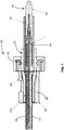
- apparatus 40 is illustrated for compressing the stent valve 10 to its compressed state 10'.
- the apparatus 40 is also configured to facilitate loading of the stent-valve 10 on to the delivering catheter 12 as part of the compression process.
- the apparatus 40 may comprise a first compressor stage 100 and/or a second compressor stage 102.
- the second stage 102 may be coupled or couplable to further compress a portion of the stent valve 10 after passing through the first compressor stage 100.
- the second compressor stage 102 may be coupled or couplable at, or to be at, an exit (or exit end) of the first compressor stage 100.
- the first compressor stage 100 may comprise a hollow channel (or hollow channel member or hollow channel body) 42, and the first compressor stage 100 may be configured for progressively compressing the stent valve 10 in response to, or in association with, longitudinal advancement of the stent valve 10 within the hollow channel 42.
- the second compressor stage 102 may be configured to compress a portion of the stent at the second compressor stage without advancement of the stent within the second compressor stage, for example, when the stent is substantially stationary (e.g. at least in the longitudinal direction).
- the stent may be advanced in incremental steps through the apparatus. While the stent is being advanced, the first compressor stage 100 progressively compresses the stent in response to (or in association with) advancement within the hollow channel. Once advancement of the stent is stopped, the second compressor stage 102 can be operated to further compress or pinch a portion of the stent thereat, for example temporarily to facilitate sliding (stepwise) a constraining sheath over or towards the further compressed portion. Thereafter, the second compressor stage 102 may be released (or relaxed), and the stent advanced a further step longitudinally, and the process repeated stepwise.
- first compressor stage 100 can provide controlled compression of the stent without excess loads
- second compressor stage 102 can provide (optionally temporary) additional local crimping or pinching at a position on the stent to facilitate sliding a relatively tightly fitting constraining sheath (e.g. of the delivery catheter) over the compressed stent.
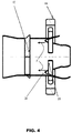
- the first compressor stage 100 may further comprise a mover 44 and a driver 46. Some or all of the components 42-46 may be disassemblable from each other, and assembled (captively or non-captively) during use of the apparatus 40.
- the hollow channel 42 may have an interior surface shaped for progressively compressing the stent-valve 10 in response to longitudinal advancement of the stent-valve 10 within the channel 42 from an entrance 52 at one end to an exit 54 at the opposite end.
- the interior surface may be generally round in cross-section, in order to maintain the round shape of the stent-valve 10 during compression.
- the interior surface may comprise one or more non-cylindrical portions 42b and 42c, for example, having a diameter that reduces progressively (e.g. converges) along the longitudinal axis of the channel 42 in a direction towards the exit 54.
- Such a shape may be referred to as a funnel shape.
- the funnel may be straight sided or concave or convex in profile.
- the interior surface may further comprise one or more generally cylindrical portions 42a.
- the interior surface may be coated to reduce the friction between the surface and the stent-valve 10 e.g. with a hydrophobic silicone based coating.
- a generally cylindrical portion 42a is provided adjacent to the entrance 52 of the channel 42.
- the cylindrical portion 42a may facilitate initial insertion of the stent-valve 10 into the channel 42 without substantial compression (and in the case of a self-expanding stent-valve, without any tendency for the stent-valve to spring back out of the entrance 52).
- a generally non-cylindrical portion 42c e.g. funnel shaped
- the non-cylindrical portion 42c may promote a convergent (e.g. conically tapered) shape at the end of the stent-valve 10 when emerging at the exit 54, to facilitate engagement of the stent-valve 10 with the stent holder 28 of the delivery catheter 12 during loading.
- the wall(s) of the channel 42 may be generally stationary or fixed, at least in a radial direction. Compression of the stent-valve 10 is achieved by advancing the stent-valve 10 within the channel 42, such that the stent-valve 10 bears against the interior surface and is forced to compress in order to advance therealong and/or therepast.
- the mover 44 may be configured for applying a longitudinal driving force generated outside the channel 42, to the stent-valve 10 within the channel 42, in order to advance the stent-valve 10 within the channel 42.
- the mover 44 may be configured for applying the longitudinal driving force from radially outside the channel 42, to the stent-valve 10, in order to advance the stent-valve 10 within the channel 42.
- the mover 44 may comprise one or more portions (e.g. limbs) 56 that slide in respective slots 58 in the wall of the channel 42, and project from outside the channel 42 through the slots 58 into the interior of the channel 42.
- the (limb) portions 56 are configured for engaging portions of the stent-valve 10 to advance the stent-valve 10 as the mover 44 is driven to translate longitudinally.
- Appling the driving force using such a mover 44 may enable the driving force to be applied to the stent-valve at one or more positions that are intermediate the opposite ends of the stent. This may enable a "pushing" force to be applied with less risk of buckling the portion of the stent under axial compression load. Additionally or alternatively, it may allow a force (“pulling” or “pushing") to be applied without interfering with the extreme ends of the stent, nor relying on or using the attachment potion 26.
- the mover 44 may enable the driving force to be applied at an extreme end of the stent-valve 10, yet solve the problem of how to advance a stent-valve (i) through a hollow channel that is longer than the stent-valve and/or (ii) applying a pushing force to a portion of the stent-valve that itself becomes compressed.
- applying the driving force using such a mover 44 may enable the driving force to be applied at one or more positions (radial and/or longitudinal) at which the stent is relatively robust and/or is less vulnerable to damage or deformation.
- the driving force is intended to be applied to the commissural support posts 22a (see Figs. 2 and 4 ).
- the driving force "F" may be applied at the junctions between the commissural support posts 22a and the alignment arches 24a connected to each respective post 22a.
- the driving force may be applied in the hollow 38 (also referred to as a valley or concavity) between two adjacent arches 24a.
- the mover 44 can contact the stent-valve 10 at a position that is (i) clear of the valve component and the skirt(s), in order to avoid damage thereto, and/or (ii) clear of the lattice structure of the anchor portion 20 that is densly packed during compression.
- the commissural support posts 22a may provide robust support for receiving the driving force, stronger than for example the stabilization portion 24.
- the (limb) portions 56 may have any suitable shape and configuration desired for engaging the stent-valve 10.
- each limb portion 56 is generally rectangular and/or generally planar in cross-section shape.
- the limb portion 56 may have a blade form.
- the cross-section shape may provide a relatively thin and/or flat surface contacting the stent-valve 10.
- the cross-section shape may define a first dimension contacting the stent-valve 10 that is smaller than a dimension of the shape that is generally transverse to the first dimension.
- Such a shape or shapes may reduce any tendency for the limb portion 56 to wedge open a space in the stent-valve 10, while still providing the limb portion 56 with adequate bending strength to transmit the driving force cantilever-wise to the stent-valve 10 through the slots 58.
- the limbs 56 may extend inwardly in a generally radial direction (e.g. perpendicular to the longitudinal axis of the channel 42).
- each limb portion 56 may be inclined relative to the radial direction.
- the angle of inclination may be about 5° or more, optionally about 10° or more, optionally about 15° or more or optionally about 20° or more. Additionally or alternatively, the angle of inclination may be not more than about 30°, optionally not more than about 25°, optionally not more than about 20°, optionally not more than about 15°, optionally not more than about 10°.
- the limb portions 56 may be inclined in a direction towards the exit 54 of the channel 42 when the mover 44 is mounted thereon (such that the inner tips of the limb portions 56 incline towards the exit 54, as indicated by arrow 56a in Fig. 4 ). Such an arrangement may prevent, or at least reduce, any tendency for the stent-valve to buckle inwardly during compression. Instead, the inclination biases the stent-valve modestly outwardly towards the surface, the presence of the surface obstructing outward buckling. In other embodiments, a different angle of inclination and/or a different direction of inclination may be used. In yet other embodiments, the limbs 56 may extend inwardly in a substantially radial direction.
- the radially inner tips or ends of the limb portions 56 are free and define a clearance (e.g. central clearance) therebetween.
- the clearance enables a portion of the delivery catheter 12 to be accommodated as the stent-valve 10 is loaded on to the delivery catheter 12 as part of the compression process.
- the clearance may be sufficiently large to enable the radially inner tips to pass over the sheaths 30 of the catheter while the mover remains assembled to the hollow channel (e.g. in coaxial alignment). This can facilitate removal of the apparatus 40 from the catheter after loading.
- the clearance may be smaller than the sheaths 30, in which case it may be appropriate to disassemble the mover from the hollow channel in order to allow the mover to pass over the sheaths 30 (e.g. moved out of coaxial alignment).
- the mover 44 may optionally further comprise a ring 60 that carries the limb portions 56, and/or from which the limb portions 56 extend.
- the ring 60 may fit around the outside of the channel 42, and be slidable longitudinally along at least a portion of the length of the channel (e.g. slidable along at least a portion corresponding to the extent of the slots 58).
- the slots 58 may be open at at least one end of the channel 42 (e.g. the entrance 52) to enable the mover to be disengaged from the channel 42 for introducing a stent-valve 10 at the entrance.
- the channel 42 may be made substantially as a single member having the slots 58 formed therein (as illustrated in the preferred embodiment).
- the channel 42 may comprise a plurality of component parts that are assemblable together to define collectively the channel form.
- the mover 44 may be driven directly by hand, but in the preferred embodiments, the driver 46 may provide additional convenience and control for generating and applying (e.g. homogenously) a driving force for the mover 44.
- the driver 46 may be movable with respect to the channel 42 and be coupled (or couplable) to the channel 42 for generating the driving force in response to relative movement applied to the driver 46.
- the driver 46 may be external to the channel 42.
- the driver 46 may comprise a rotary member 62 rotated by hand or by using a suitable tool.
- the rotary member 62 may be rotatable around the longitudinal axis of the channel 42.
- the rotary member 62 may be coupled (or couplable) to the channel 42 by means of a screw thread 64 and/or a helical guide, in order to generate longitudinal displacement in response to rotation of the rotary member 62.
- the driver 46 e.g. the rotary member
- the (limb) portions 56 transmit the driving force to the stent-valve 10 to advance the stent-valve 10 within the channel 42.
- the channel 42 has a generally cylindrical exterior portion carrying the screw thread 64 for the rotary member 62.
- the rotary member 62 may be unscrewed and disassembled from the thread 64, for example, at the entrance 52 of the channel 42. Such unscrewing/disassembly permits removal of the mover 44 for insertion of the stent-valve into the entrance 52 of the channel 42, and subsequent refitting of the mover 44 and the rotary member 62.
- the second compressor stage 102 may be releasably coupled or couplable at, or to be at, the exit 54 of the channel 42.
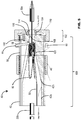
- the second compressor stage 102 may comprise a crimper for crimping, or pinching, a portion of the stent valve 10 within the second compressor stage 102.
- the crimper comprises a plurality of movable elements in the form of chuck jaws 104.
- the chuck jaws 104 may be separate from each other, but in the preferred embodiment, the chuck jaws 104 are integral with a supporting base or washer 106.
- the washer 106 and jaws 104 are provided by a one-piece plastics molding.
- the chuck jaws 104 are biased naturally to an outward or relaxed position, and are displaceable inwardly by contact with a conical ramp surface 108 of a surrounding actuator or driver 110.
- the actuator 110 is threadedly movable with respect to the channel 42, such that rotation of the actuator 110 results in its axial movement, causing the conical ramp surface 108 to bear against the chuck jaws 104 forcing them inwards.
- the chuck jaws 104 control the size of an aperture of the crimper.
- the base 106 may restrained against rotation (from frictional engagement by the actuator 110) by means of a keyed connection 112 between the base 106 and the channel 42.
- the keyed connection may be formed, for example, by at least one axial pin or other projection of one component fitting in an aperture of the other component.
- a liner 114 fitting inside the chuck jaws 104 may provide a contact surface of the crimper for bearing against the stent-valve 10.
- the liner 114 may have a generally ring shape, either of closed-loop or open-loop (or split) configuration.
- the liner 114 may be of plastics (for example, elastic or non-elastic).
- the liner is of polyether block amide (PEBA).
- the second compressor stage 102 may be releasably attachable to the first compressor stage 100 by a screw threaded connection.
- the actuator 110 provides both a releasable screw threaded connection to the channel 42, and crimper operation as described above.
- Initial turning (e.g. tightening) of the screw-threaded actuator 110 can mechanically couple the compressor stages together. Further turning (e.g. tightening) of the actuator 110 operates the crimper.
- movement of actuator 110 is reversed.
- Initial reverse movement e.g. untightening
- relaxes the crimper releases or disconnects the compressor stages from each other.
- the loading tube apparatus 120 may generally comprise a plurality of (at least first and second) segments 122a, 122b that are assemble around a portion of a delivery catheter to define a tubular shape or form 122; and at least one retainer for retaining the plurality of segments in the assembled shape.
- the retainer comprises an overtube 124, and a threaded nut 126 that is securable to a mouth of the overtube 124.
- the segments 122a and 122b enable a tubular form to assembled having an inner diameter that would otherwise be impossible or difficult to slide over a catheter sheath, at least in use.
- the retainer enables the segments to be secured in position, and can have an inner diameter sufficiently large to be slid on to the catheter.
- the tubular form 122 may provided a precisely dimensioned form fit with respect to a sheath of the catheter, for example, with respect to the proximal sheath 30b.
- the tubular form 122 may reinforce the proximal sheath 30b to enable a portion of the stent-valve 10 to be directed compressed and loaded into the proximal sheath 30b without overstressing the sheath material.
- the segments 122a and 122b may of generally transparent material, such as transparent plastics, to enable viewing of the stent within the sheath 30b.
- the overtube 124 may also be of transparent material and/or may include a viewing window or cut-out 128, to facilitate unhindered viewing while the overtube 124 is in place.
- the apparatus 40 and /or 120 may further comprise an intermediate loading tube 130 to further facilitate manipulation of the stent-valve 10, and to assist loading.
- the loading tube 130 may have a generally cylindrical form, dimension to slide, with a form fit, over the sheaths 30 and 30b.
- the segments 122 may have a step change in internal diameter (in the region indicated at 132 in Fig. 7 ) to accommodate the intermediate tube around the sheath.
- the apparatus 40 and/or 120 may further comprise an interior support 140 in the form of a metallic tube or shaft 142 insertable into the guidewire lumen of the delivery catheter from the distal end.
- the shaft may terminate in a plastics handle 144 by which the interior support may be manipulated by hand, and a counter-force applied manually to the distal end of the delivery catheter in use.
- a technique for compressing and loading a stent-valve 10 on to a delivery catheter 12 of Fig. 1 In order to compress and load a stent-valve 10 into a delivery catheter 12, the sheaths 30a and 30b of the delivery catheter 12 are first opened. The stent-valve 10 is loaded into the mouth of the channel 42, the mover 44 placed over the entrance, and secured with the driver 46. The apparatus 40 containing the stent-valve 10 may then be placed over the distal end of the delivery catheter 12, and slid in a proximal direction beyond the distal sheath 30a.
- the stent-valve 10 is initially compressed by rotating the driver 46, to advance the stent-valve 10 within the channel 42 in a distal direction with respect to the catheter 12.
- the attachment elements of the stent-valve emerge at the exit of the apparatus 40, they may be manually fitted on to the stent-holder of the catheter, optionally using the second compressor stage 102 to further compress or pinch the stent-valve to narrow the attachment elements to mate with the stent-holder.
- a portion of the stent-valve 10 is loaded into the first sheath 30a by a sequence of, step-wise: (i) rotating the driver 46 to advance the stent-valve 10; (ii) after rotation of the driver 46 is stopped, operating the crimper to further compress or pinch the portion of the stent-valve 10 at the exit of the apparatus; (iii) sliding the first sheath 30a proximally to cover the newly exposed portion of the stent-valve; (iv) relaxing the crimper; and (v) repeating the steps (i)-(iv) one or more times.
- the intermediate loading tube 130 may be slid over the partly compressed stent-valve, from the distal end of the delivery catheter, to further compress the stent-valve.
- the apparatus 40 may be removed from the delivery catheter.
- the loading tube apparatus 120 can be assembled around the second or proximal sheath 30b, and optionally the intermediate tube 130.
- the segments 122 are fitted into place, and secured by the overtube 124 and nut 126.
- the opposite portion of the stent-valve is loaded into the second sheath 30b by progressively closing the sheath 30b over the respective portion of the stent-valve 10.
- the interior support 140 may be fitted and used to apply to the distal end of the delivery catheter 10 a counter force to balance the force needed for forcibly translating the second sheath 30b over the stent-valve 10.
- the loading tube apparatus 120 and the intermediate tube 130 may translate together in unison with the second sheath 30b, to provide continuous support as the sheath 30b moves over the stent-valve 10.
- the loading tube apparatus 120 may be disassembled and removed, the intermediate loading tube 130 removed, and the interior support 140 withdrawn from the distal end of the delivery catheter.
- the above components may be made of any suitable material or materials, including metal and/or plastics and/or ceramics.
- the channel 42, the driver 46, the loading tube assembly 120, and the intermediate loading tube 130 may of plastics; and/or the ring 60 of the mover 44 may be of metal; and/or the limbs 56 of the mover 44 may be of plastics (e.g. to avoid metal-metal contact with the stent component 14).
- the limbs 56 could be of metal or ceramics, either optionally being coated or carrying a cover of plastics.
- the ring 60 and the limbs 56 of the mover 44 could be of plastics, e.g. integrally moulded together.
- the loading tube 48 and/or the channel 42 and/or the loading tube apparatus 120 may optionally be transparent or translucent to enable the operator to see the state of the stent-valve 10 during compression, and to aid loading and manipulation of the delivery catheter 12.
Landscapes
- Health & Medical Sciences (AREA)
- Cardiology (AREA)
- Engineering & Computer Science (AREA)
- Biomedical Technology (AREA)
- Heart & Thoracic Surgery (AREA)
- Transplantation (AREA)
- Oral & Maxillofacial Surgery (AREA)
- Vascular Medicine (AREA)
- Life Sciences & Earth Sciences (AREA)
- Animal Behavior & Ethology (AREA)
- General Health & Medical Sciences (AREA)
- Public Health (AREA)
- Veterinary Medicine (AREA)
- Prostheses (AREA)
- Media Introduction/Drainage Providing Device (AREA)
Claims (17)
- Vorrichtung (40, 120), die zum Komprimieren einer Herzstentklappe (10) auf einem maximalen Außendurchmesser von ungefähr 10 mm oder weniger zum Laden in einen Freisetzungskatheter (12) ausgelegt ist, wobei die Vorrichtung (40, 120) das Folgende umfasst- eine erste Kompressionsstufe (100) zum Komprimieren der Stentklappe (10); und- eine zweite Kompressionsstufe (102), die mit der ersten Kompressionsstufe (100) verbunden oder verbindbar ist und zur weiteren Kompression eines Teils der Stentklappe (10) nach Durchlaufen der ersten Kompressionsstufe (100) ausgelegt ist,wobei die erste Kompressionsstufe (100) einen hohlen Kanal (42) umfasst und die erste Kompressionsstufe (100) zur progressiven Kompression der Stentklappe als Reaktion auf oder in Zusammenhang mit einer Längsvorschiebebewegung der Stentklappe im hohlen Kanal (42) ausgelegt ist, dadurch gekennzeichnet, dass
die zweite Kompressionsstufe (102) zum Komprimieren eines Teils der Stentklappe auf der zweiten Kompressionsstufe (102) ohne Vorschieben der Stentklappe in der zweiten Kompressionsstufe (102) ausgelegt ist. - Vorrichtung (40, 120) nach Anspruch 1, ausgelegt zur Verwendung beim Komprimieren einer Herzstentklappe (10), die einen maximalen Außendurchmesser in ihrem expandierten Zustand von ca. 25 mm bis ca. 35 mm aufweist.
- Vorrichtung (40, 120) nach einem der vorhergehenden Ansprüche, wobei die zweite Kompressionsstufe (102) zum Aufbringen einer radialen Kraft von mindestens 50N ausgelegt ist.
- Vorrichtung (40, 120) nach einem der vorhergehenden Ansprüche, wobei die zweite Kompressionsstufe (102) lösbar an einem Ausgang der ersten Kompressionsstufe (100) angebracht ist oder sich daran befinden soll.
- Vorrichtung (40, 120) nach einem der vorhergehenden Ansprüche, wobei die zweite Kompressionsstufe (102) ein Crimpwerkzeug umfasst.
- Vorrichtung (40, 120) nach Anspruch 5, wobei die Quetsche eine Vielzahl von beweglichen Elementen umfasst.
- Vorrichtung (40, 120) nach Anspruch 5 oder 6, wobei das Crimpwerkzeug Backen (104) umfasst, die ein Spannfutter definieren.
- Vorrichtung (40, 120) nach einem der vorhergehenden Ansprüche, wobei die ersten und zweiten Kompressionsstufen (100, 102) von jeweiligen rotierenden Betätigungsgliedern (46, 110) betätigt werden, die um eine gemeinsame Achse, fakultativ eine Längsachse der Vorrichtung drehbar sind.
- Vorrichtung (40, 120) nach einem der vorhergehenden Ansprüche, wobei die zweite Kompressionsstufe (102) über ein Schraubengewinde-Betätigungsglied (110) zur Betätigung der zweiten Kompressionsstufe (102) lösbar an der ersten Kompressionsstufe (100) befestigbar ist.
- Vorrichtung (40, 120) nach einem der vorhergehenden Ansprüche, wobei die erste Kompressionsstufe (100) ein oder mehr der folgenden umfasst: (i) ein Bewegungsmittel (44) zum Ausüben einer Schubkraft von radial außerhalb des Kanals (42) auf eine Stentklappe (10) im Kanal (42); und/oder (ii) eine Antriebsvorrichtung (46) zum Ausüben einer Schubkraft radial außerhalb des Kanals (42) auf einen Teil des Bewegungsmittels (44) radial außerhalb des Kanals (42).
- Vorrichtung (40, 120) nach Anspruch 10, wobei das Bewegungsmittel einen Ring umfasst, von dem mehrere Glieder nach innen ragen, wobei die Glieder in Schlitzen durch eine Wand des Kanals gleiten, um eine Stentklappe im Kanal mit einer Schubkraft zu beaufschlagen.
- Vorrichtung (40, 120) nach einem der vorhergehenden Ansprüche, ferner umfassend:eine Vielzahl von Segmenten (122a, 122b), die um einen Teil eines Freisetzungskatheters (12) zur Definition einer röhrenförmigen Gestalt zusammensetzbar sind; undmindestens einen Halter zum Festhalten der Vielzahl von Segmenten (122a, 122b) im zusammengesetzten Zustand.
- Vorrichtung (40, 120) nach Anspruch 12, wobei der Halter mindestens eine Gewindemutter (126) und/oder ein unterstützendes Überrohr (124) umfasst.
- Verfahren zum Komprimieren einer Stentklappe (10), wobei das Verfahren das Folgende umfasst:(a) Bereitstellen einer Vorrichtung, umfassend eine erste Kompressionsstufe (100), die einen Längskanal (42) aufweist; und eine zweite Kompressionsstufe (102), die mit der ersten Kompressionsstufe (100) verbunden oder verbindbar ist, zur Kompression eines Teils der Stentklappe nach Durchlaufen der ersten Kompressionsstufe;(b) Betätigen eines Betätigungsglieds (46) der ersten Kompressionsstufe durch Drehung, um die Stentklappe im hohlen Kanal (42) vorzuschieben, um die Stentklappe als Reaktion auf eine oder in Zusammenhang mit einer Längsvorschiebebewegung im hohlen Kanal (42) progressiv zu komprimieren, gekennzeichnet durch(c) Betätigen der zweiten Kompressionsstufe (102) zum weiteren Komprimieren eines Teils der Stentklappe ohne weiteres Vorschieben der Stentklappe in der zweiten Kompressionsstufe.
- Verfahren nach Anspruch 14, wobei der Schritt des Betätigens der zweiten Kompressionsstufe das Betätigen eines Betätigungsglieds (110) der zweiten Kompressionsstufe durch Drehung umfasst.
- System, umfassend:ein Freisetzungskatheter (12) mit einer Rückhalteregion zum Unterbringen einer Herzstentklappe, wobei erste und zweite Hüllen (30a, 30b) zur Verschiebung in entgegengesetzte Richtungen zum Schließen über jeweiligen Abschnitten der Stentklappe in einem komprimierten Zustand an der Rückhalteregion ausgelegt sind; undeine Vorrichtung (40, 120) zur Verwendung zum Komprimieren der Stentklappe (10) zum Laden in den Freisetzungskatheter (12), wobei die Vorrichtung (40, 120) das Folgende umfasst:eine erste Kompressionsstufe (100) zum Komprimieren der Stentklappe (10); undeine zweite Kompressionsstufe (102), die mit der ersten Kompressionsstufe (100) verbunden oder verbindbar ist und zur weiteren Kompression eines Teils der Stentklappe (10) nach Durchlaufen der ersten Kompressionsstufe (100) ausgelegt ist,wobei die erste Kompressionsstufe (100) einen hohlen Kanal (42) umfasst und die erste Kompressionsstufe (100) zur progressiven Kompression der Stentklappe als Reaktion auf eine oder in Zusammenhang mit einer Längsvorschiebebewegung der Stentklappe im hohlen Kanal (42) ausgelegt ist, dadurch gekennzeichnet, dassdie zweite Kompressionsstufe (102) zum Komprimieren eines Teils des Stents auf der zweiten Kompressionsstufe (102) ohne Vorschieben der Stentklappe in der zweiten Kompressionsstufe (102) ausgelegt ist.
- System nach Anspruch 16, wobei die Vorrichtung (40, 120) eine Vorrichtung (40, 120) nach einem der Ansprüche 1 bis 13 ist.
Priority Applications (3)
| Application Number | Priority Date | Filing Date | Title |
|---|---|---|---|
| EP21205429.0A EP4000560A1 (de) | 2013-09-16 | 2014-09-16 | Verfahren und vorrichtung zum komprimieren/laden von stentklappen |
| EP14766978.2A EP3046511B1 (de) | 2013-09-16 | 2014-09-16 | Verfahren und vorrichtung zum komprimieren / laden von stentklappen |
| EP18163259.7A EP3360514B1 (de) | 2013-09-16 | 2014-09-16 | Verfahren und vorrichtung zum komprimieren/laden von stentklappen |
Applications Claiming Priority (3)
| Application Number | Priority Date | Filing Date | Title |
|---|---|---|---|
| EP13184650 | 2013-09-16 | ||
| EP14766978.2A EP3046511B1 (de) | 2013-09-16 | 2014-09-16 | Verfahren und vorrichtung zum komprimieren / laden von stentklappen |
| PCT/EP2014/069696 WO2015036617A2 (en) | 2013-09-16 | 2014-09-16 | Method and apparatus for compressing/loading stent-valves |
Related Child Applications (2)
| Application Number | Title | Priority Date | Filing Date |
|---|---|---|---|
| EP21205429.0A Division EP4000560A1 (de) | 2013-09-16 | 2014-09-16 | Verfahren und vorrichtung zum komprimieren/laden von stentklappen |
| EP18163259.7A Division EP3360514B1 (de) | 2013-09-16 | 2014-09-16 | Verfahren und vorrichtung zum komprimieren/laden von stentklappen |
Publications (2)
| Publication Number | Publication Date |
|---|---|
| EP3046511A2 EP3046511A2 (de) | 2016-07-27 |
| EP3046511B1 true EP3046511B1 (de) | 2018-03-28 |
Family
ID=49231263
Family Applications (3)
| Application Number | Title | Priority Date | Filing Date |
|---|---|---|---|
| EP18163259.7A Active EP3360514B1 (de) | 2013-09-16 | 2014-09-16 | Verfahren und vorrichtung zum komprimieren/laden von stentklappen |
| EP21205429.0A Pending EP4000560A1 (de) | 2013-09-16 | 2014-09-16 | Verfahren und vorrichtung zum komprimieren/laden von stentklappen |
| EP14766978.2A Active EP3046511B1 (de) | 2013-09-16 | 2014-09-16 | Verfahren und vorrichtung zum komprimieren / laden von stentklappen |
Family Applications Before (2)
| Application Number | Title | Priority Date | Filing Date |
|---|---|---|---|
| EP18163259.7A Active EP3360514B1 (de) | 2013-09-16 | 2014-09-16 | Verfahren und vorrichtung zum komprimieren/laden von stentklappen |
| EP21205429.0A Pending EP4000560A1 (de) | 2013-09-16 | 2014-09-16 | Verfahren und vorrichtung zum komprimieren/laden von stentklappen |
Country Status (5)
| Country | Link |
|---|---|
| US (4) | US10245145B2 (de) |
| EP (3) | EP3360514B1 (de) |
| JP (1) | JP6659934B2 (de) |
| CN (1) | CN105722476B (de) |
| WO (1) | WO2015036617A2 (de) |
Cited By (32)
| Publication number | Priority date | Publication date | Assignee | Title |
|---|---|---|---|---|
| US10149756B2 (en) | 2008-09-29 | 2018-12-11 | Edwards Lifesciences Cardiaq Llc | Heart valve |
| US10179044B2 (en) | 2014-05-19 | 2019-01-15 | Edwards Lifesciences Cardiaq Llc | Replacement mitral valve |
| US10226335B2 (en) | 2015-06-22 | 2019-03-12 | Edwards Lifesciences Cardiaq Llc | Actively controllable heart valve implant and method of controlling same |
| US10485660B2 (en) | 2010-06-21 | 2019-11-26 | Edwards Lifesciences Cardiaq Llc | Replacement heart valve |
| US10575951B2 (en) | 2015-08-26 | 2020-03-03 | Edwards Lifesciences Cardiaq Llc | Delivery device and methods of use for transapical delivery of replacement mitral valve |
| US10583000B2 (en) | 2013-03-14 | 2020-03-10 | Edwards Lifesciences Cardiaq Llc | Prosthesis for atraumatically grasping intralumenal tissue and methods of delivery |
| US10610362B2 (en) | 2010-09-23 | 2020-04-07 | Edwards Lifesciences Cardiaq Llc | Replacement heart valves, delivery devices and methods |
| US10716664B2 (en) | 2013-03-14 | 2020-07-21 | Edwards Lifesciences Cardiaq Llc | Prosthesis for atraumatically grasping intralumenal tissue and methods of delivery |
| US10758345B2 (en) | 2015-08-26 | 2020-09-01 | Edwards Lifesciences Cardiaq Llc | Replacement heart valves and methods of delivery |
| US10813757B2 (en) | 2017-07-06 | 2020-10-27 | Edwards Lifesciences Corporation | Steerable rail delivery system |
| US10842620B2 (en) | 2015-06-23 | 2020-11-24 | Edwards Lifesciences Cardiaq Llc | Systems and methods for anchoring and sealing a prosthetic heart valve |
| US10856984B2 (en) | 2017-08-25 | 2020-12-08 | Neovasc Tiara Inc. | Sequentially deployed transcatheter mitral valve prosthesis |
| US10940001B2 (en) | 2012-05-30 | 2021-03-09 | Neovasc Tiara Inc. | Methods and apparatus for loading a prosthesis onto a delivery system |
| US10952849B2 (en) | 2014-02-21 | 2021-03-23 | Edwards Lifesciences Cardiaq Llc | Prosthesis, delivery device and methods of use |
| US11051934B2 (en) | 2018-02-28 | 2021-07-06 | Edwards Lifesciences Corporation | Prosthetic mitral valve with improved anchors and seal |
| US11058536B2 (en) | 2004-10-02 | 2021-07-13 | Edwards Lifesciences Cardiaq Llc | Method for replacement of heart valve |
| US11141265B2 (en) | 2006-07-28 | 2021-10-12 | Edwards Lifesciences Cardiaq Llc | Percutaneous valve prosthesis and system and method for implanting the same |
| US11253364B2 (en) | 2015-08-28 | 2022-02-22 | Edwards Lifesciences Cardiaq Llc | Steerable delivery system for replacement mitral valve and methods of use |
| US11311376B2 (en) | 2019-06-20 | 2022-04-26 | Neovase Tiara Inc. | Low profile prosthetic mitral valve |
| US11357622B2 (en) | 2016-01-29 | 2022-06-14 | Neovase Tiara Inc. | Prosthetic valve for avoiding obstruction of outflow |
| US11376119B2 (en) | 2009-04-15 | 2022-07-05 | Edwards Lifesciences Cardiaq Llc | Vascular implant and delivery system |
| US11389291B2 (en) | 2013-04-04 | 2022-07-19 | Neovase Tiara Inc. | Methods and apparatus for delivering a prosthetic valve to a beating heart |
| US11389292B2 (en) | 2015-04-30 | 2022-07-19 | Edwards Lifesciences Cardiaq Llc | Replacement mitral valve, delivery system for replacement mitral valve and methods of use |
| US11413139B2 (en) | 2011-11-23 | 2022-08-16 | Neovasc Tiara Inc. | Sequentially deployed transcatheter mitral valve prosthesis |
| US11419720B2 (en) | 2010-05-05 | 2022-08-23 | Neovasc Tiara Inc. | Transcatheter mitral valve prosthesis |
| US11464631B2 (en) | 2016-11-21 | 2022-10-11 | Neovasc Tiara Inc. | Methods and systems for rapid retraction of a transcatheter heart valve delivery system |
| US11491006B2 (en) | 2019-04-10 | 2022-11-08 | Neovasc Tiara Inc. | Prosthetic valve with natural blood flow |
| US11497602B2 (en) | 2012-02-14 | 2022-11-15 | Neovasc Tiara Inc. | Methods and apparatus for engaging a valve prosthesis with tissue |
| US11602429B2 (en) | 2019-04-01 | 2023-03-14 | Neovasc Tiara Inc. | Controllably deployable prosthetic valve |
| US11684474B2 (en) | 2018-01-25 | 2023-06-27 | Edwards Lifesciences Corporation | Delivery system for aided replacement valve recapture and repositioning post-deployment |
| US11737872B2 (en) | 2018-11-08 | 2023-08-29 | Neovasc Tiara Inc. | Ventricular deployment of a transcatheter mitral valve prosthesis |
| US11779742B2 (en) | 2019-05-20 | 2023-10-10 | Neovasc Tiara Inc. | Introducer with hemostasis mechanism |
Families Citing this family (43)
| Publication number | Priority date | Publication date | Assignee | Title |
|---|---|---|---|---|
| WO2007058857A2 (en) | 2005-11-10 | 2007-05-24 | Arshad Quadri | Balloon-expandable, self-expanding, vascular prosthesis connecting stent |
| EP3360514B1 (de) * | 2013-09-16 | 2021-11-03 | Symetis SA | Verfahren und vorrichtung zum komprimieren/laden von stentklappen |
| US10195025B2 (en) * | 2014-05-12 | 2019-02-05 | Edwards Lifesciences Corporation | Prosthetic heart valve |
| US10179042B2 (en) * | 2015-06-12 | 2019-01-15 | St. Jude Medical, Cardiology Division, Inc. | Heart valve repair and replacement |
| EP3313330A4 (de) * | 2015-06-29 | 2019-03-20 | 480 Biomedical, Inc. | Gerüstlade- und -abgabesysteme |
| US10639147B2 (en) * | 2016-06-24 | 2020-05-05 | Edwards Lifesciences Corporation | System and method for crimping a prosthetic valve |
| RU2650038C1 (ru) * | 2016-12-30 | 2018-04-06 | Общество с ограниченной ответственностью "СЕВЕН САНС" | Устройство и способ для безопасного позиционирования коронарного стента в коронарных артериях |
| US10653523B2 (en) | 2017-01-19 | 2020-05-19 | 4C Medical Technologies, Inc. | Systems, methods and devices for delivery systems, methods and devices for implanting prosthetic heart valves |
| US10561495B2 (en) | 2017-01-24 | 2020-02-18 | 4C Medical Technologies, Inc. | Systems, methods and devices for two-step delivery and implantation of prosthetic heart valve |
| WO2018165356A1 (en) * | 2017-03-10 | 2018-09-13 | St. Jude Medical, Cardiology Division, Inc. | Transseptal mitral valve delivery system |
| US10918473B2 (en) * | 2017-07-18 | 2021-02-16 | Edwards Lifesciences Corporation | Transcatheter heart valve storage container and crimping mechanism |
| CN107702915B (zh) * | 2017-11-21 | 2019-08-20 | 北京信息职业技术学院 | 一种导管拆装检测装置 |
| WO2019195860A2 (en) | 2018-04-04 | 2019-10-10 | Vdyne, Llc | Devices and methods for anchoring transcatheter heart valve |
| JP7109657B2 (ja) | 2018-05-23 | 2022-07-29 | コーシム・ソチエタ・ア・レスポンサビリタ・リミタータ | 心臓弁プロテーゼ |
| US11857441B2 (en) | 2018-09-04 | 2024-01-02 | 4C Medical Technologies, Inc. | Stent loading device |
| US11344413B2 (en) | 2018-09-20 | 2022-05-31 | Vdyne, Inc. | Transcatheter deliverable prosthetic heart valves and methods of delivery |
| US11278437B2 (en) | 2018-12-08 | 2022-03-22 | Vdyne, Inc. | Compression capable annular frames for side delivery of transcatheter heart valve replacement |
| US10321995B1 (en) | 2018-09-20 | 2019-06-18 | Vdyne, Llc | Orthogonally delivered transcatheter heart valve replacement |
| US11071627B2 (en) | 2018-10-18 | 2021-07-27 | Vdyne, Inc. | Orthogonally delivered transcatheter heart valve frame for valve in valve prosthesis |
| US10595994B1 (en) | 2018-09-20 | 2020-03-24 | Vdyne, Llc | Side-delivered transcatheter heart valve replacement |
| US11109969B2 (en) | 2018-10-22 | 2021-09-07 | Vdyne, Inc. | Guidewire delivery of transcatheter heart valve |
| WO2020123486A1 (en) | 2018-12-10 | 2020-06-18 | Boston Scientific Scimed, Inc. | Medical device delivery system including a resistance member |
| US11253359B2 (en) | 2018-12-20 | 2022-02-22 | Vdyne, Inc. | Proximal tab for side-delivered transcatheter heart valves and methods of delivery |
| US10653522B1 (en) | 2018-12-20 | 2020-05-19 | Vdyne, Inc. | Proximal tab for side-delivered transcatheter heart valve prosthesis |
| CN111374813A (zh) * | 2018-12-29 | 2020-07-07 | 上海微创心通医疗科技有限公司 | 支架输送装置和支架装载方法 |
| US11185409B2 (en) | 2019-01-26 | 2021-11-30 | Vdyne, Inc. | Collapsible inner flow control component for side-delivered transcatheter heart valve prosthesis |
| US11273032B2 (en) | 2019-01-26 | 2022-03-15 | Vdyne, Inc. | Collapsible inner flow control component for side-deliverable transcatheter heart valve prosthesis |
| EP4364706A2 (de) | 2019-03-05 | 2024-05-08 | Vdyne, Inc. | Trikuspidalregurgitationssteuerungsvorrichtungen für orthogonale transkatheterherzklappenprothese |
| US10758346B1 (en) | 2019-03-14 | 2020-09-01 | Vdyne, Inc. | A2 clip for side-delivered transcatheter mitral valve prosthesis |
| US10631983B1 (en) | 2019-03-14 | 2020-04-28 | Vdyne, Inc. | Distal subannular anchoring tab for side-delivered transcatheter valve prosthesis |
| US11076956B2 (en) | 2019-03-14 | 2021-08-03 | Vdyne, Inc. | Proximal, distal, and anterior anchoring tabs for side-delivered transcatheter mitral valve prosthesis |
| US11173027B2 (en) | 2019-03-14 | 2021-11-16 | Vdyne, Inc. | Side-deliverable transcatheter prosthetic valves and methods for delivering and anchoring the same |
| CA3138875A1 (en) | 2019-05-04 | 2020-11-12 | Vdyne, Inc. | Cinch device and method for deployment of a side-delivered prosthetic heart valve in a native annulus |
| CN110251273B (zh) * | 2019-05-23 | 2022-09-13 | 沛嘉医疗科技(苏州)有限公司 | 一种经导管输送瓣膜预装载系统装置 |
| CN114599316A (zh) | 2019-08-20 | 2022-06-07 | 维迪内股份有限公司 | 用于可侧面递送经导管人工瓣膜的递送和取回装置和方法 |
| AU2020337235A1 (en) | 2019-08-26 | 2022-03-24 | Vdyne, Inc. | Side-deliverable transcatheter prosthetic valves and methods for delivering and anchoring the same |
| CN113131411A (zh) * | 2020-01-10 | 2021-07-16 | 苏州市鑫联冷热缩科技有限公司 | 一种加强型电缆修补片 |
| US11234813B2 (en) | 2020-01-17 | 2022-02-01 | Vdyne, Inc. | Ventricular stability elements for side-deliverable prosthetic heart valves and methods of delivery |
| US11931253B2 (en) | 2020-01-31 | 2024-03-19 | 4C Medical Technologies, Inc. | Prosthetic heart valve delivery system: ball-slide attachment |
| CN117915870A (zh) | 2021-07-13 | 2024-04-19 | 波士顿科学国际有限公司 | 用于对准心脏瓣膜与输送系统的对准工具 |
| WO2023064362A1 (en) * | 2021-10-13 | 2023-04-20 | Boston Scientific Scimed, Inc. | Device and method for compressing and loading a stent |
| CN116251289B (zh) * | 2022-10-25 | 2023-12-01 | 心擎医疗(苏州)股份有限公司 | 导管泵及折叠导管泵的泵头的方法 |
| WO2024091935A1 (en) | 2022-10-26 | 2024-05-02 | Boston Scientific Scimed, Inc. | Alignment tool for aligning heart valve with delivery system |
Family Cites Families (29)
| Publication number | Priority date | Publication date | Assignee | Title |
|---|---|---|---|---|
| US5672169A (en) * | 1996-04-10 | 1997-09-30 | Medtronic, Inc. | Stent mounting device |
| US5893867A (en) * | 1996-11-06 | 1999-04-13 | Percusurge, Inc. | Stent positioning apparatus and method |
| AUPO700897A0 (en) * | 1997-05-26 | 1997-06-19 | William A Cook Australia Pty Ltd | A method and means of deploying a graft |
| US5893852A (en) * | 1998-04-28 | 1999-04-13 | Advanced Cardiovascular Systems, Inc. | Stent crimping tool and method of use |
| US6618921B1 (en) * | 2000-11-16 | 2003-09-16 | Scimed Life Systems, Inc. | Bare stent ship and crimp device |
| DE602004026756D1 (de) * | 2003-10-15 | 2010-06-02 | Cook Inc | Haltevorrichtung für ein prothesenablagesystem |
| US20050149166A1 (en) * | 2003-11-08 | 2005-07-07 | Schaeffer Darin G. | Branch vessel prosthesis with anchoring device and method |
| EP2298319A1 (de) * | 2005-04-04 | 2011-03-23 | Sinexus, Inc. | Vorrichtung und Verfahren zur Behandlung von Erkrankungen der Nasennebenhöhlen |
| US20070239271A1 (en) * | 2006-04-10 | 2007-10-11 | Than Nguyen | Systems and methods for loading a prosthesis onto a minimally invasive delivery system |
| US8006535B2 (en) * | 2007-07-12 | 2011-08-30 | Sorin Biomedica Cardio S.R.L. | Expandable prosthetic valve crimping device |
| US8747458B2 (en) * | 2007-08-20 | 2014-06-10 | Medtronic Ventor Technologies Ltd. | Stent loading tool and method for use thereof |
| CA2732355A1 (en) * | 2008-08-01 | 2010-02-04 | Intersect Ent, Inc. | Methods and devices for crimping self-expanding devices |
| US8359721B2 (en) * | 2008-09-04 | 2013-01-29 | Cook Medical Technologies Llc | Sliding split-sleeve implant compressor |
| US20100121424A1 (en) * | 2008-11-12 | 2010-05-13 | Petr Kubena | Stent compression tool |
| WO2010130789A1 (en) * | 2009-05-15 | 2010-11-18 | Jenavalve Technology Inc. | Device for compressing a stent as well as system and method for loading a stent into a medical delivery system |
| US8468667B2 (en) | 2009-05-15 | 2013-06-25 | Jenavalve Technology, Inc. | Device for compressing a stent |
| WO2011035253A1 (en) * | 2009-09-18 | 2011-03-24 | Mahon Joseph A | Adjustable prosthetic interfaces and related systems and methods |
| US9021670B2 (en) * | 2010-08-17 | 2015-05-05 | St. Jude Medical, Cardiology Division, Inc. | Device for collapsing and loading a heart valve into a minimally invasive delivery system |
| US9414915B2 (en) | 2010-09-24 | 2016-08-16 | Symetis Sa | Stent valve, delivery apparatus and method therefor |
| US9155619B2 (en) * | 2011-02-25 | 2015-10-13 | Edwards Lifesciences Corporation | Prosthetic heart valve delivery apparatus |
| EP2520251A1 (de) * | 2011-05-05 | 2012-11-07 | Symetis SA | Verfahren und Vorrichtung zum Zusammendrücken von Stentklappen |
| US8414528B2 (en) * | 2011-05-27 | 2013-04-09 | Abbott Cardiovascular Systems Inc. | Polymer scaffold sheaths |
| CN103826576A (zh) * | 2011-06-20 | 2014-05-28 | 机械解决方案有限公司 | 用于将支架装载到导管中的装置及方法 |
| US8652145B2 (en) * | 2011-12-14 | 2014-02-18 | Edwards Lifesciences Corporation | System and method for crimping a prosthetic valve |
| US9345573B2 (en) * | 2012-05-30 | 2016-05-24 | Neovasc Tiara Inc. | Methods and apparatus for loading a prosthesis onto a delivery system |
| US9308346B2 (en) * | 2013-02-01 | 2016-04-12 | Medtronic, Inc. | Devices and methods for crimping and loading a collapsible device into a delivery system |
| US9333077B2 (en) * | 2013-03-12 | 2016-05-10 | Medtronic Vascular Galway Limited | Devices and methods for preparing a transcatheter heart valve system |
| US9351860B2 (en) * | 2013-03-14 | 2016-05-31 | Cook Medical Technologies Llc | Loading tool for capturing stent points |
| EP3360514B1 (de) * | 2013-09-16 | 2021-11-03 | Symetis SA | Verfahren und vorrichtung zum komprimieren/laden von stentklappen |
-
2014
- 2014-09-16 EP EP18163259.7A patent/EP3360514B1/de active Active
- 2014-09-16 EP EP21205429.0A patent/EP4000560A1/de active Pending
- 2014-09-16 WO PCT/EP2014/069696 patent/WO2015036617A2/en active Application Filing
- 2014-09-16 US US15/022,525 patent/US10245145B2/en active Active
- 2014-09-16 EP EP14766978.2A patent/EP3046511B1/de active Active
- 2014-09-16 CN CN201480062076.5A patent/CN105722476B/zh not_active Expired - Fee Related
- 2014-09-16 JP JP2016542340A patent/JP6659934B2/ja active Active
-
2019
- 2019-04-01 US US16/371,214 patent/US10682228B2/en active Active
-
2020
- 2020-02-26 US US16/802,035 patent/US11786372B2/en active Active
-
2023
- 2023-09-07 US US18/462,684 patent/US20230414352A1/en active Pending
Cited By (53)
| Publication number | Priority date | Publication date | Assignee | Title |
|---|---|---|---|---|
| US11058536B2 (en) | 2004-10-02 | 2021-07-13 | Edwards Lifesciences Cardiaq Llc | Method for replacement of heart valve |
| US11304803B2 (en) | 2004-10-02 | 2022-04-19 | Edwards Lifesciences Cardiaq Llc | Method for replacement of heart valve |
| US11141265B2 (en) | 2006-07-28 | 2021-10-12 | Edwards Lifesciences Cardiaq Llc | Percutaneous valve prosthesis and system and method for implanting the same |
| US10646334B2 (en) | 2008-09-29 | 2020-05-12 | Edwards Lifesciences Cardiaq Llc | Heart valve |
| US11589983B2 (en) | 2008-09-29 | 2023-02-28 | Edwards Lifesciences Cardiaq Llc | Heart valve |
| US11819404B2 (en) | 2008-09-29 | 2023-11-21 | Edwards Lifesciences Cardiaq Llc | Heart valve |
| US10149756B2 (en) | 2008-09-29 | 2018-12-11 | Edwards Lifesciences Cardiaq Llc | Heart valve |
| US11376119B2 (en) | 2009-04-15 | 2022-07-05 | Edwards Lifesciences Cardiaq Llc | Vascular implant and delivery system |
| US10524901B2 (en) | 2009-09-29 | 2020-01-07 | Edwards Lifesciences Cardiaq Llc | Replacement heart valve |
| US11419720B2 (en) | 2010-05-05 | 2022-08-23 | Neovasc Tiara Inc. | Transcatheter mitral valve prosthesis |
| US10639146B2 (en) | 2010-06-21 | 2020-05-05 | Edwards Lifesciences Cardiaq Llc | Replacement heart valve |
| US11452597B2 (en) | 2010-06-21 | 2022-09-27 | Edwards Lifesciences Cardiaq Llc | Replacement heart valve |
| US10485660B2 (en) | 2010-06-21 | 2019-11-26 | Edwards Lifesciences Cardiaq Llc | Replacement heart valve |
| US10610362B2 (en) | 2010-09-23 | 2020-04-07 | Edwards Lifesciences Cardiaq Llc | Replacement heart valves, delivery devices and methods |
| US10881510B2 (en) | 2010-09-23 | 2021-01-05 | Edwards Lifesciences Cardiaq Llc | Replacement heart valves, delivery devices and methods |
| US11413139B2 (en) | 2011-11-23 | 2022-08-16 | Neovasc Tiara Inc. | Sequentially deployed transcatheter mitral valve prosthesis |
| US11497602B2 (en) | 2012-02-14 | 2022-11-15 | Neovasc Tiara Inc. | Methods and apparatus for engaging a valve prosthesis with tissue |
| US10940001B2 (en) | 2012-05-30 | 2021-03-09 | Neovasc Tiara Inc. | Methods and apparatus for loading a prosthesis onto a delivery system |
| US11389294B2 (en) | 2012-05-30 | 2022-07-19 | Neovasc Tiara Inc. | Methods and apparatus for loading a prosthesis onto a delivery system |
| US11617650B2 (en) | 2012-05-30 | 2023-04-04 | Neovasc Tiara Inc. | Methods and apparatus for loading a prosthesis onto a delivery system |
| US10583000B2 (en) | 2013-03-14 | 2020-03-10 | Edwards Lifesciences Cardiaq Llc | Prosthesis for atraumatically grasping intralumenal tissue and methods of delivery |
| US10716664B2 (en) | 2013-03-14 | 2020-07-21 | Edwards Lifesciences Cardiaq Llc | Prosthesis for atraumatically grasping intralumenal tissue and methods of delivery |
| US11951001B2 (en) | 2013-03-14 | 2024-04-09 | Edwards Lifesciences Cardiaq Llc | Prosthesis for atraumatically grapsing intralumenal tissue and methods of delivery |
| US11324591B2 (en) | 2013-03-14 | 2022-05-10 | Edwards Lifesciences Cardiaq Llc | Prosthesis for atraumatically grasping intralumenal tissue and methods of delivery |
| US11389291B2 (en) | 2013-04-04 | 2022-07-19 | Neovase Tiara Inc. | Methods and apparatus for delivering a prosthetic valve to a beating heart |
| US10952849B2 (en) | 2014-02-21 | 2021-03-23 | Edwards Lifesciences Cardiaq Llc | Prosthesis, delivery device and methods of use |
| US11633279B2 (en) | 2014-02-21 | 2023-04-25 | Edwards Lifesciences Cardiaq Llc | Prosthesis, delivery device and methods of use |
| US11045313B2 (en) | 2014-05-19 | 2021-06-29 | Edwards Lifesciences Cardiaq Llc | Replacement mitral valve |
| US10179044B2 (en) | 2014-05-19 | 2019-01-15 | Edwards Lifesciences Cardiaq Llc | Replacement mitral valve |
| US11389292B2 (en) | 2015-04-30 | 2022-07-19 | Edwards Lifesciences Cardiaq Llc | Replacement mitral valve, delivery system for replacement mitral valve and methods of use |
| US11083576B2 (en) | 2015-06-22 | 2021-08-10 | Edwards Lifesciences Cardiaq Llc | Actively controllable heart valve implant and method of controlling same |
| US10226335B2 (en) | 2015-06-22 | 2019-03-12 | Edwards Lifesciences Cardiaq Llc | Actively controllable heart valve implant and method of controlling same |
| US11844690B2 (en) | 2015-06-23 | 2023-12-19 | Edwards Lifesciences Cardiaq Llc | Systems and methods for anchoring and sealing a prosthetic heart valve |
| US10842620B2 (en) | 2015-06-23 | 2020-11-24 | Edwards Lifesciences Cardiaq Llc | Systems and methods for anchoring and sealing a prosthetic heart valve |
| US11278405B2 (en) | 2015-08-26 | 2022-03-22 | Edwards Lifesciences Cardiaq Llc | Delivery device and methods of use for transapical delivery of replacement valve |
| US10575951B2 (en) | 2015-08-26 | 2020-03-03 | Edwards Lifesciences Cardiaq Llc | Delivery device and methods of use for transapical delivery of replacement mitral valve |
| US10758345B2 (en) | 2015-08-26 | 2020-09-01 | Edwards Lifesciences Cardiaq Llc | Replacement heart valves and methods of delivery |
| US11253364B2 (en) | 2015-08-28 | 2022-02-22 | Edwards Lifesciences Cardiaq Llc | Steerable delivery system for replacement mitral valve and methods of use |
| US11357622B2 (en) | 2016-01-29 | 2022-06-14 | Neovase Tiara Inc. | Prosthetic valve for avoiding obstruction of outflow |
| US11464631B2 (en) | 2016-11-21 | 2022-10-11 | Neovasc Tiara Inc. | Methods and systems for rapid retraction of a transcatheter heart valve delivery system |
| US11883287B2 (en) | 2017-07-06 | 2024-01-30 | Edwards Lifesciences Corporation | Steerable rail delivery system |
| US11123186B2 (en) | 2017-07-06 | 2021-09-21 | Edwards Lifesciences Corporation | Steerable delivery system and components |
| US10813757B2 (en) | 2017-07-06 | 2020-10-27 | Edwards Lifesciences Corporation | Steerable rail delivery system |
| US10856984B2 (en) | 2017-08-25 | 2020-12-08 | Neovasc Tiara Inc. | Sequentially deployed transcatheter mitral valve prosthesis |
| US11793640B2 (en) | 2017-08-25 | 2023-10-24 | Neovasc Tiara Inc. | Sequentially deployed transcatheter mitral valve prosthesis |
| US11684474B2 (en) | 2018-01-25 | 2023-06-27 | Edwards Lifesciences Corporation | Delivery system for aided replacement valve recapture and repositioning post-deployment |
| US11051934B2 (en) | 2018-02-28 | 2021-07-06 | Edwards Lifesciences Corporation | Prosthetic mitral valve with improved anchors and seal |
| US11737872B2 (en) | 2018-11-08 | 2023-08-29 | Neovasc Tiara Inc. | Ventricular deployment of a transcatheter mitral valve prosthesis |
| US11602429B2 (en) | 2019-04-01 | 2023-03-14 | Neovasc Tiara Inc. | Controllably deployable prosthetic valve |
| US11491006B2 (en) | 2019-04-10 | 2022-11-08 | Neovasc Tiara Inc. | Prosthetic valve with natural blood flow |
| US11779742B2 (en) | 2019-05-20 | 2023-10-10 | Neovasc Tiara Inc. | Introducer with hemostasis mechanism |
| US11931254B2 (en) | 2019-06-20 | 2024-03-19 | Neovasc Tiara Inc. | Low profile prosthetic mitral valve |
| US11311376B2 (en) | 2019-06-20 | 2022-04-26 | Neovase Tiara Inc. | Low profile prosthetic mitral valve |
Also Published As
| Publication number | Publication date |
|---|---|
| CN105722476A (zh) | 2016-06-29 |
| US10245145B2 (en) | 2019-04-02 |
| EP3360514A1 (de) | 2018-08-15 |
| US10682228B2 (en) | 2020-06-16 |
| CN105722476B (zh) | 2018-07-20 |
| WO2015036617A3 (en) | 2015-04-30 |
| WO2015036617A2 (en) | 2015-03-19 |
| EP4000560A1 (de) | 2022-05-25 |
| JP2016530046A (ja) | 2016-09-29 |
| EP3046511A2 (de) | 2016-07-27 |
| US20190290427A1 (en) | 2019-09-26 |
| US11786372B2 (en) | 2023-10-17 |
| EP3360514B1 (de) | 2021-11-03 |
| US20200205971A1 (en) | 2020-07-02 |
| US20230414352A1 (en) | 2023-12-28 |
| US20160228249A1 (en) | 2016-08-11 |
| JP6659934B2 (ja) | 2020-03-04 |
Similar Documents
| Publication | Publication Date | Title |
|---|---|---|
| US11786372B2 (en) | Method and apparatus for compressing/loading stent-valves | |
| US20230404735A1 (en) | Method and apparatus for compressing/loading stent-valves | |
| US11833040B2 (en) | System and method for crimping a prosthetic valve | |
| EP2560589B1 (de) | Freisetzungssysteme für herzklappenprothesen | |
| EP2919712A1 (de) | Anordnung und verfahren zum einsetzen einer klappenprothese |
Legal Events
| Date | Code | Title | Description |
|---|---|---|---|
| PUAI | Public reference made under article 153(3) epc to a published international application that has entered the european phase |
Free format text: ORIGINAL CODE: 0009012 |
|
| 17P | Request for examination filed |
Effective date: 20160406 |
|
| AK | Designated contracting states |
Kind code of ref document: A2 Designated state(s): AL AT BE BG CH CY CZ DE DK EE ES FI FR GB GR HR HU IE IS IT LI LT LU LV MC MK MT NL NO PL PT RO RS SE SI SK SM TR |
|
| AX | Request for extension of the european patent |
Extension state: BA ME |
|
| DAX | Request for extension of the european patent (deleted) | ||
| RIC1 | Information provided on ipc code assigned before grant |
Ipc: A61F 2/24 20060101AFI20170818BHEP Ipc: A61F 2/95 20130101ALN20170818BHEP Ipc: A61F 2/97 20130101ALN20170818BHEP |
|
| GRAP | Despatch of communication of intention to grant a patent |
Free format text: ORIGINAL CODE: EPIDOSNIGR1 |
|
| STAA | Information on the status of an ep patent application or granted ep patent |
Free format text: STATUS: GRANT OF PATENT IS INTENDED |
|
| RIC1 | Information provided on ipc code assigned before grant |
Ipc: A61F 2/95 20130101ALN20170915BHEP Ipc: A61F 2/24 20060101AFI20170915BHEP Ipc: A61F 2/97 20130101ALN20170915BHEP |
|
| INTG | Intention to grant announced |
Effective date: 20171009 |
|
| GRAJ | Information related to disapproval of communication of intention to grant by the applicant or resumption of examination proceedings by the epo deleted |
Free format text: ORIGINAL CODE: EPIDOSDIGR1 |
|
| STAA | Information on the status of an ep patent application or granted ep patent |
Free format text: STATUS: REQUEST FOR EXAMINATION WAS MADE |
|
| GRAR | Information related to intention to grant a patent recorded |
Free format text: ORIGINAL CODE: EPIDOSNIGR71 |
|
| GRAS | Grant fee paid |
Free format text: ORIGINAL CODE: EPIDOSNIGR3 |
|
| STAA | Information on the status of an ep patent application or granted ep patent |
Free format text: STATUS: GRANT OF PATENT IS INTENDED |
|
| GRAA | (expected) grant |
Free format text: ORIGINAL CODE: 0009210 |
|
| STAA | Information on the status of an ep patent application or granted ep patent |
Free format text: STATUS: THE PATENT HAS BEEN GRANTED |
|
| INTC | Intention to grant announced (deleted) | ||
| RIC1 | Information provided on ipc code assigned before grant |
Ipc: A61F 2/97 20130101ALN20180207BHEP Ipc: A61F 2/24 20060101AFI20180207BHEP Ipc: A61F 2/95 20130101ALN20180207BHEP |
|
| INTG | Intention to grant announced |
Effective date: 20180213 |
|
| AK | Designated contracting states |
Kind code of ref document: B1 Designated state(s): AL AT BE BG CH CY CZ DE DK EE ES FI FR GB GR HR HU IE IS IT LI LT LU LV MC MK MT NL NO PL PT RO RS SE SI SK SM TR |
|
| REG | Reference to a national code |
Ref country code: GB Ref legal event code: FG4D |
|
| REG | Reference to a national code |
Ref country code: CH Ref legal event code: EP |
|
| REG | Reference to a national code |
Ref country code: AT Ref legal event code: REF Ref document number: 982703 Country of ref document: AT Kind code of ref document: T Effective date: 20180415 |
|
| REG | Reference to a national code |
Ref country code: IE Ref legal event code: FG4D |
|
| REG | Reference to a national code |
Ref country code: DE Ref legal event code: R096 Ref document number: 602014023029 Country of ref document: DE |
|
| PG25 | Lapsed in a contracting state [announced via postgrant information from national office to epo] |
Ref country code: FI Free format text: LAPSE BECAUSE OF FAILURE TO SUBMIT A TRANSLATION OF THE DESCRIPTION OR TO PAY THE FEE WITHIN THE PRESCRIBED TIME-LIMIT Effective date: 20180328 Ref country code: LT Free format text: LAPSE BECAUSE OF FAILURE TO SUBMIT A TRANSLATION OF THE DESCRIPTION OR TO PAY THE FEE WITHIN THE PRESCRIBED TIME-LIMIT Effective date: 20180328 Ref country code: NO Free format text: LAPSE BECAUSE OF FAILURE TO SUBMIT A TRANSLATION OF THE DESCRIPTION OR TO PAY THE FEE WITHIN THE PRESCRIBED TIME-LIMIT Effective date: 20180628 Ref country code: HR Free format text: LAPSE BECAUSE OF FAILURE TO SUBMIT A TRANSLATION OF THE DESCRIPTION OR TO PAY THE FEE WITHIN THE PRESCRIBED TIME-LIMIT Effective date: 20180328 |
|
| REG | Reference to a national code |
Ref country code: NL Ref legal event code: MP Effective date: 20180328 |
|
| REG | Reference to a national code |
Ref country code: LT Ref legal event code: MG4D |
|
| PG25 | Lapsed in a contracting state [announced via postgrant information from national office to epo] |
Ref country code: GR Free format text: LAPSE BECAUSE OF FAILURE TO SUBMIT A TRANSLATION OF THE DESCRIPTION OR TO PAY THE FEE WITHIN THE PRESCRIBED TIME-LIMIT Effective date: 20180629 Ref country code: BG Free format text: LAPSE BECAUSE OF FAILURE TO SUBMIT A TRANSLATION OF THE DESCRIPTION OR TO PAY THE FEE WITHIN THE PRESCRIBED TIME-LIMIT Effective date: 20180628 Ref country code: RS Free format text: LAPSE BECAUSE OF FAILURE TO SUBMIT A TRANSLATION OF THE DESCRIPTION OR TO PAY THE FEE WITHIN THE PRESCRIBED TIME-LIMIT Effective date: 20180328 Ref country code: SE Free format text: LAPSE BECAUSE OF FAILURE TO SUBMIT A TRANSLATION OF THE DESCRIPTION OR TO PAY THE FEE WITHIN THE PRESCRIBED TIME-LIMIT Effective date: 20180328 Ref country code: LV Free format text: LAPSE BECAUSE OF FAILURE TO SUBMIT A TRANSLATION OF THE DESCRIPTION OR TO PAY THE FEE WITHIN THE PRESCRIBED TIME-LIMIT Effective date: 20180328 |
|
| PG25 | Lapsed in a contracting state [announced via postgrant information from national office to epo] |
Ref country code: PL Free format text: LAPSE BECAUSE OF FAILURE TO SUBMIT A TRANSLATION OF THE DESCRIPTION OR TO PAY THE FEE WITHIN THE PRESCRIBED TIME-LIMIT Effective date: 20180328 Ref country code: EE Free format text: LAPSE BECAUSE OF FAILURE TO SUBMIT A TRANSLATION OF THE DESCRIPTION OR TO PAY THE FEE WITHIN THE PRESCRIBED TIME-LIMIT Effective date: 20180328 Ref country code: NL Free format text: LAPSE BECAUSE OF FAILURE TO SUBMIT A TRANSLATION OF THE DESCRIPTION OR TO PAY THE FEE WITHIN THE PRESCRIBED TIME-LIMIT Effective date: 20180328 Ref country code: ES Free format text: LAPSE BECAUSE OF FAILURE TO SUBMIT A TRANSLATION OF THE DESCRIPTION OR TO PAY THE FEE WITHIN THE PRESCRIBED TIME-LIMIT Effective date: 20180328 Ref country code: AL Free format text: LAPSE BECAUSE OF FAILURE TO SUBMIT A TRANSLATION OF THE DESCRIPTION OR TO PAY THE FEE WITHIN THE PRESCRIBED TIME-LIMIT Effective date: 20180328 Ref country code: RO Free format text: LAPSE BECAUSE OF FAILURE TO SUBMIT A TRANSLATION OF THE DESCRIPTION OR TO PAY THE FEE WITHIN THE PRESCRIBED TIME-LIMIT Effective date: 20180328 Ref country code: IT Free format text: LAPSE BECAUSE OF FAILURE TO SUBMIT A TRANSLATION OF THE DESCRIPTION OR TO PAY THE FEE WITHIN THE PRESCRIBED TIME-LIMIT Effective date: 20180328 |
|
| PG25 | Lapsed in a contracting state [announced via postgrant information from national office to epo] |
Ref country code: CZ Free format text: LAPSE BECAUSE OF FAILURE TO SUBMIT A TRANSLATION OF THE DESCRIPTION OR TO PAY THE FEE WITHIN THE PRESCRIBED TIME-LIMIT Effective date: 20180328 Ref country code: SM Free format text: LAPSE BECAUSE OF FAILURE TO SUBMIT A TRANSLATION OF THE DESCRIPTION OR TO PAY THE FEE WITHIN THE PRESCRIBED TIME-LIMIT Effective date: 20180328 Ref country code: SK Free format text: LAPSE BECAUSE OF FAILURE TO SUBMIT A TRANSLATION OF THE DESCRIPTION OR TO PAY THE FEE WITHIN THE PRESCRIBED TIME-LIMIT Effective date: 20180328 |
|
| PGFP | Annual fee paid to national office [announced via postgrant information from national office to epo] |
Ref country code: CH Payment date: 20180913 Year of fee payment: 5 |
|
| REG | Reference to a national code |
Ref country code: AT Ref legal event code: MK05 Ref document number: 982703 Country of ref document: AT Kind code of ref document: T Effective date: 20180328 |
|
| PG25 | Lapsed in a contracting state [announced via postgrant information from national office to epo] |
Ref country code: PT Free format text: LAPSE BECAUSE OF FAILURE TO SUBMIT A TRANSLATION OF THE DESCRIPTION OR TO PAY THE FEE WITHIN THE PRESCRIBED TIME-LIMIT Effective date: 20180730 |
|
| REG | Reference to a national code |
Ref country code: DE Ref legal event code: R097 Ref document number: 602014023029 Country of ref document: DE |
|
| PG25 | Lapsed in a contracting state [announced via postgrant information from national office to epo] |
Ref country code: AT Free format text: LAPSE BECAUSE OF FAILURE TO SUBMIT A TRANSLATION OF THE DESCRIPTION OR TO PAY THE FEE WITHIN THE PRESCRIBED TIME-LIMIT Effective date: 20180328 Ref country code: DK Free format text: LAPSE BECAUSE OF FAILURE TO SUBMIT A TRANSLATION OF THE DESCRIPTION OR TO PAY THE FEE WITHIN THE PRESCRIBED TIME-LIMIT Effective date: 20180328 |
|
| PLBE | No opposition filed within time limit |
Free format text: ORIGINAL CODE: 0009261 |
|
| STAA | Information on the status of an ep patent application or granted ep patent |
Free format text: STATUS: NO OPPOSITION FILED WITHIN TIME LIMIT |
|
| 26N | No opposition filed |
Effective date: 20190103 |
|
| PG25 | Lapsed in a contracting state [announced via postgrant information from national office to epo] |
Ref country code: MC Free format text: LAPSE BECAUSE OF FAILURE TO SUBMIT A TRANSLATION OF THE DESCRIPTION OR TO PAY THE FEE WITHIN THE PRESCRIBED TIME-LIMIT Effective date: 20180328 |
|
| PG25 | Lapsed in a contracting state [announced via postgrant information from national office to epo] |
Ref country code: SI Free format text: LAPSE BECAUSE OF FAILURE TO SUBMIT A TRANSLATION OF THE DESCRIPTION OR TO PAY THE FEE WITHIN THE PRESCRIBED TIME-LIMIT Effective date: 20180328 |
|
| REG | Reference to a national code |
Ref country code: BE Ref legal event code: MM Effective date: 20180930 |
|
| PG25 | Lapsed in a contracting state [announced via postgrant information from national office to epo] |
Ref country code: LU Free format text: LAPSE BECAUSE OF NON-PAYMENT OF DUE FEES Effective date: 20180916 |
|
| PG25 | Lapsed in a contracting state [announced via postgrant information from national office to epo] |
Ref country code: BE Free format text: LAPSE BECAUSE OF NON-PAYMENT OF DUE FEES Effective date: 20180930 Ref country code: FR Free format text: LAPSE BECAUSE OF NON-PAYMENT OF DUE FEES Effective date: 20180930 |
|
| PG25 | Lapsed in a contracting state [announced via postgrant information from national office to epo] |
Ref country code: MT Free format text: LAPSE BECAUSE OF NON-PAYMENT OF DUE FEES Effective date: 20180916 |
|
| PG25 | Lapsed in a contracting state [announced via postgrant information from national office to epo] |
Ref country code: TR Free format text: LAPSE BECAUSE OF FAILURE TO SUBMIT A TRANSLATION OF THE DESCRIPTION OR TO PAY THE FEE WITHIN THE PRESCRIBED TIME-LIMIT Effective date: 20180328 |
|
| REG | Reference to a national code |
Ref country code: CH Ref legal event code: PL |
|
| PG25 | Lapsed in a contracting state [announced via postgrant information from national office to epo] |
Ref country code: HU Free format text: LAPSE BECAUSE OF FAILURE TO SUBMIT A TRANSLATION OF THE DESCRIPTION OR TO PAY THE FEE WITHIN THE PRESCRIBED TIME-LIMIT; INVALID AB INITIO Effective date: 20140916 Ref country code: MK Free format text: LAPSE BECAUSE OF NON-PAYMENT OF DUE FEES Effective date: 20180328 Ref country code: CY Free format text: LAPSE BECAUSE OF FAILURE TO SUBMIT A TRANSLATION OF THE DESCRIPTION OR TO PAY THE FEE WITHIN THE PRESCRIBED TIME-LIMIT Effective date: 20180328 |
|
| PG25 | Lapsed in a contracting state [announced via postgrant information from national office to epo] |
Ref country code: CH Free format text: LAPSE BECAUSE OF NON-PAYMENT OF DUE FEES Effective date: 20190930 Ref country code: LI Free format text: LAPSE BECAUSE OF NON-PAYMENT OF DUE FEES Effective date: 20190930 Ref country code: IS Free format text: LAPSE BECAUSE OF FAILURE TO SUBMIT A TRANSLATION OF THE DESCRIPTION OR TO PAY THE FEE WITHIN THE PRESCRIBED TIME-LIMIT Effective date: 20180728 |
|
| REG | Reference to a national code |
Ref country code: DE Ref legal event code: R081 Ref document number: 602014023029 Country of ref document: DE Owner name: BOSTON SCIENTIFIC MEDICAL DEVICE LIMITED, IE Free format text: FORMER OWNER: SYMETIS SA, ECUBLENS, CH |
|
| REG | Reference to a national code |
Ref country code: GB Ref legal event code: 732E Free format text: REGISTERED BETWEEN 20211216 AND 20211222 |
|
| REG | Reference to a national code |
Ref country code: GB Ref legal event code: 732E Free format text: REGISTERED BETWEEN 20211223 AND 20211229 |
|
| P01 | Opt-out of the competence of the unified patent court (upc) registered |
Effective date: 20230509 |
|
| PGFP | Annual fee paid to national office [announced via postgrant information from national office to epo] |
Ref country code: IE Payment date: 20230823 Year of fee payment: 10 Ref country code: GB Payment date: 20230823 Year of fee payment: 10 |
|
| PGFP | Annual fee paid to national office [announced via postgrant information from national office to epo] |
Ref country code: DE Payment date: 20230822 Year of fee payment: 10 |