EP3045995A1 - Procede de traçage a partir de combinaison de pre-positionnement et mode manuel - Google Patents
Procede de traçage a partir de combinaison de pre-positionnement et mode manuel Download PDFInfo
- Publication number
- EP3045995A1 EP3045995A1 EP15201542.6A EP15201542A EP3045995A1 EP 3045995 A1 EP3045995 A1 EP 3045995A1 EP 15201542 A EP15201542 A EP 15201542A EP 3045995 A1 EP3045995 A1 EP 3045995A1
- Authority
- EP
- European Patent Office
- Prior art keywords
- robot
- approach
- calibration point
- automatic
- automatic approach
- Prior art date
- Legal status (The legal status is an assumption and is not a legal conclusion. Google has not performed a legal analysis and makes no representation as to the accuracy of the status listed.)
- Withdrawn
Links
Images

Classifications
-
- G—PHYSICS
- G05—CONTROLLING; REGULATING
- G05B—CONTROL OR REGULATING SYSTEMS IN GENERAL; FUNCTIONAL ELEMENTS OF SUCH SYSTEMS; MONITORING OR TESTING ARRANGEMENTS FOR SUCH SYSTEMS OR ELEMENTS
- G05B19/00—Programme-control systems
- G05B19/02—Programme-control systems electric
- G05B19/42—Recording and playback systems, i.e. in which the programme is recorded from a cycle of operations, e.g. the cycle of operations being manually controlled, after which this record is played back on the same machine
- G05B19/423—Teaching successive positions by walk-through, i.e. the tool head or end effector being grasped and guided directly, with or without servo-assistance, to follow a path
-
- B—PERFORMING OPERATIONS; TRANSPORTING
- B25—HAND TOOLS; PORTABLE POWER-DRIVEN TOOLS; MANIPULATORS
- B25J—MANIPULATORS; CHAMBERS PROVIDED WITH MANIPULATION DEVICES
- B25J9/00—Programme-controlled manipulators
- B25J9/16—Programme controls
- B25J9/1656—Programme controls characterised by programming, planning systems for manipulators
- B25J9/1664—Programme controls characterised by programming, planning systems for manipulators characterised by motion, path, trajectory planning
Definitions
- the present invention relates to a method for controlling a robot, and further to the use of the method for calibrating a robot.
- a robot is a universal motion machine with multiple axes.
- the movements of the axes are freely programmable and can optionally also be sensor-guided.
- the robot Before a robot can be used, for example, to work on a workpiece, the robot usually has to be calibrated, that is, for example, a reference between the coordinate system of the robot (robot coordinate system or robot foot coordinate system) and a coordinate system of the environment can be established.
- the relative position between the robot and its surroundings or the workpiece can thus be determined by the robot or the robot controller.
- Such a calibration is necessary so that the robot controller receives the required data, where the workpiece is and this can thus be processed accordingly.
- the calibration of the robot may be necessary, for example, when a robot is repositioned or brought into a new environment, or even when a new workpiece is to be processed by the robot.
- a location-flexible robot unit often changes position or a fixed robot unit is to process frequently changing workpieces
- a frequent (re) calibration is necessary.
- a quick method for measuring is desirable.
- the present invention is thus based on the object of enabling a simple and efficient measuring of a robot to a workpiece or to an environment. It is a particular object of the present invention to provide a method by which a location-robotic robot can be quickly measured in new environments. A further object of the present invention is to provide a method with which a rapid measurement of a robot is possible for frequently changing workpieces.
- the invention relates to a method for controlling a robot, and in particular for controlling a portable robot.
- the invention preferably comprises the use of the method according to the invention for measuring a robot.
- the robot can be, for example, a multi-axis articulated arm robot, on whose flange a tool or end effector can be attached.
- a measuring tip whose properties or dimensions are provided to a robot controller is advantageously located on the robot flange or on the tool.
- the measuring tip is MRK-compatible, so that safe use in a human-robot collaboration (MRK) is possible.
- the method according to the invention has an automatic approach to at least one calibration point based on a path planning of the robot.
- this automatic approach a spatial distance between the robot or the flange / the tool / the measuring tip and the calibration point is reduced, without a manual movement of the robot by an operator takes place.
- the approach can thus take place, for example, according to a programming or a program of the robot. However, an actual reaching of the calibration point does not take place.
- the method comprises, after each automatic approach, a manual approach of the calibration point and detection of coordinates of the manually approached calibration point.
- this calibration point is approached manually.
- the robot is controlled by the operator.
- calibration point can in this case include a specific point in the environment of the robot or in the working space of the robot, or also relate to a specific point on a workpiece or on the surface of a workpiece.
- the expert understands the Einmessembl advantageous to choose so that they are suitable in the sense of the present invention for measuring the robot.
- the Einmessembl are associated with unique features of the environment or the workpiece.
- the calibration points may include a bore, a cone, or a corner.
- the calibration points may preferably be selected such that a suitable coordinate system can be spanned with them.
- the automatic approach is an automatic approach of the robot to the at least one calibration point.
- the movements (approaching or approaching) of the robot are thus understood here as movements of the flange / tool / the measuring tip or the tool center point (TCP), and are referred to below as movements of the robot or movements of the robot Called TCPs.
- the pose of the robot changes.
- the pose of the robot also changes as a result of the manual startup of the calibration point.
- the automatic driving comprises driving the robot kinematics based on the path planning of the robot.
- the robot or the drives of the robot kinematics are actively controlled or regulated by, for example, the robot control in order to carry out the automatic control of the calibration point.
- the router automatically moves into a calibration zone, which preferably describes a relatively narrow range in which the calibration point is located. The eventual reaching or starting of the calibration point is then done manually. Since this only small distances must be covered, only a small operator or control competence of the operator is necessary.
- the manual starting comprises hand-moving the robot, e.g. by means of a control panel or a joystick or similar
- the manual start-up involves direct (direct) guiding of the robot by hand.
- the robot is therefore packed and guided directly by an operator. Thanks to this intuitive and simple operation, the calibration point can be reached very quickly and precisely.
- the manual starting comprises operation of the robot in a mode of operation with compliance control (impedance control) and in particular with active compliance control.
- Active compliance control designates e.g. the control of the manipulator due to a deviation of the end effector.
- This is particularly suitable for guiding robots by an operator, for example as part of a teach-in process, since this regulation allows a very safe operation for the user.
- the influence of the gravitation is preferably also compensated, so that the robot, in this operating mode, holds its current pose when it is not moved or guided. This simplifies the operation.
- the robot comprises several axes.
- sensors for detecting the forces and / or torques acting on the axles are provided.
- this also includes means by which, for example, the motor currents of the drives of the robot can be measured in order indirectly to determine the forces and moments acting on the axes.
- these sensors are particularly preferred as Torque sensors, for example, based on strain gauges, executed and provided in the joints of the robot. Based on the detected forces or detected torques, a guiding movement (for example, by a direct manual guidance of the operator) can be detected and correspondingly reacted, whereby the hand-guided movement or manual starting is made possible without the use of external control consoles or control panels.
- the automatic approach preferably comprises an automatic approach to at least two, more preferably to at least three and more preferably to exactly three calibration points.
- the person skilled in the art understands that for each of these calibration points the automatic approach, manual approach and detection of coordinates takes place individually.
- the person skilled in the art also understands that the different calibration points are advantageously not identical.
- By measuring several calibration points the accuracy and accuracy of the calibration procedure can be increased.
- By measuring three calibration points it is possible in particular to span a coordinate system precisely. For this purpose, preferably the origin and two further points of the new base or of the new coordinate system are measured. So only a small number of measuring points have to be measured to measure the robot.
- the inventive method further comprises calculating a coordinate system based on the detected coordinates of the calibration points.
- a base coordinate system based on the acquired coordinates is calculated.
- all further points necessary for programming a process can be specified and stored relative to the coordinate system in the further course.
- no search algorithm is used for automatically approaching the calibration point.
- the automatic pre-positioning of the robot can thus be done without much effort, so that the robot or the TCP is moved quickly into the vicinity of the Einmessembls.
- the precise calibration itself is done by means of intuitive manual guidance by the operator.
- the method of controlling a robot is performed during the course of a robot program.
- the method according to the invention can thus be implemented as a substep of a process in automatic mode; the process in automatic mode does not have to be interrupted in order to measure the robot.
- the automatic starting comprises starting the calibration point up to a spatial distance of 1 to 30 cm, more preferably 1 to 20 cm, and more preferably 1 to 10 cm. Automatic startup thus moves the robot into the immediate vicinity of the calibration point. So it is not a large operator competence or control competence of an operator necessary to then manually approach the Einmesstician.
- the invention relates to a robot system, comprising a robot and in particular a multi-axis articulated arm robot.
- the robot system has a robot controller, wherein the robot controller is set up to execute steps for controlling the robot according to the method according to the invention.
- the robot controller is set up to perform an automatic approach to at least one calibration point based on a path planning of the robot, and to permit a manual approach of the calibration point after each automatic approach, and subsequently to detect the coordinates of the manually approached calibration point.
- the robot also comprises one or more sensors for detecting the forces and / or torques acting on the axles.
- the sensor or the sensors can be provided for this purpose at corresponding points of the manipulator or robot arm.
- a 6D force / torque sensor may also be provided, for example, on or in the robot foot.
- the robot or the robot system is location-flexible and / or portable.
- the robot or the robot system are therefore not installed stationary, but can for example be used variably at different processing stations.
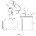
- a robot system comprising a robot 10.
- This robot 10 is designed here in the form of a multi-axis articulated-arm robot 10.
- the robot 10 shown by way of example is a lightweight robot of the type KUKA LBR iiwa, which comprises seven joints which can be moved independently of one another.
- the illustrated robot 10 has seven axes of rotation, which enable complex movements of the robot 10.
- Force and / or torque sensors are advantageously provided in the joints of the robot 10 with which forces and / or torques acting on the robot 10 can be detected.
- the robot 10 is installed by means of a foot 14 on a location-flexible unit 11.
- the location-flexible unit 11, such as a suitable cart, can be moved to various positions, for example, to various processing stations in an industrial manufacturing facility. Since the robot 10 is connected to the location-flexible unit 11, consequently, the robot 10 is also considered to be location-flexible.
- the robot 10 has at its flange 12 a measuring tip 13, which can be used to measure the robot, for example, on a workpiece.
- a measuring tip 13 can be detachably connected to the flange 12, or that an end effector can be coupled to the flange 12, which in turn guides a measuring tip.
- a workbench 15 is shown, on which a workpiece 16 is located, which in turn is to be processed by the robot 10.
- the robot 10 must first be measured.
- the robot 10 is to be measured with respect to the recess 17 of the workpiece 16. Since the position of the robot 10 or the location-flexible unit 11 can not be set precisely, the exact position of the recess 17 relative to the robot coordinates of the robot controller is provided by the measuring.
- the robot 10 or the measuring tip 13 thus initially approaches the recess 17 automatically, and reaches, for example, the point 18, which is referred to here as the preliminary position 18.
- the recess 17 is approached manually.
- the robot 10 is grasped at its flange 12 and guided by hand.
- an operating switch can be provided on the flange, which must be pressed by the operator in order to unlock the manual operation of the robot.
- the operator guides the robot on the flange, so that the measuring tip 13 is moved from the pre-position 18 to the recess 17.
- the robot can recognize this manual guidance of the operator and control the drives in the joints accordingly, so that the pose of the robot 10 changes and the measuring tip 13 moves accordingly.
- the exact coordinates (with respect to the robot coordinate system) of the measuring tip 13, which is located in the recess 17, are determined and stored in the robot controller. Based on these coordinates, the workpiece can now be approached by the robot for processing in normal working mode.
- Fig. 2 schematically the sequence of a method according to the invention for controlling a robot is shown.
- the method begins in step 20.
- the robot is calibrated by the operator.
- a corresponding measuring tip is attached to the robot flange or to an end effector of the robot and measured as TCP.
- the robot moves such that the robot's TCP approaches a first calibration point. This approach is done automatically based on the path planning.
- the robot is thus programmed so that it moves with the measuring tip in the vicinity of the Einmesstician.
- step 23 the handling of the robot is made possible. Now the worker or the operator guides the measuring tip to the defined calibration point. The robot recognizes the guiding movement and adapts its pose or structure accordingly so that it can follow the lead.
- step 26 the operation mode of the manual operation is ended.
- step 22 it is determined whether all calibration points have already been measured or the corresponding coordinates have been recorded for this purpose. If this is not the case, the method is continued in step 22 for the next, here for the second calibration point.
- the robot thus automatically approaches the second calibration point based on the path planning of the robot.
- step 23 the operating mode of the manual control is activated, and the second calibration point is approached manually.
- the coordinates are stored in step 25, and so on, until all desired or required calibration points are detected.
- a coordinate system to the three stored Einmessembl is calculated in step 28. Since the origin and two further points of the new base are preferably given by the three calibration points, a corresponding base coordinate system can be easily calculated.
- the method described can thus be used to enable a rapid change of workpieces or robot positions, since the calibration of the robot is fast and intuitive.
Landscapes
- Engineering & Computer Science (AREA)
- Robotics (AREA)
- Physics & Mathematics (AREA)
- General Physics & Mathematics (AREA)
- Automation & Control Theory (AREA)
- Mechanical Engineering (AREA)
- Manipulator (AREA)
- Numerical Control (AREA)
Applications Claiming Priority (1)
| Application Number | Priority Date | Filing Date | Title |
|---|---|---|---|
| DE102015200319.1A DE102015200319A1 (de) | 2015-01-13 | 2015-01-13 | Einmessverfahren aus Kombination von Vorpositionierung und Handführen |
Publications (1)
| Publication Number | Publication Date |
|---|---|
| EP3045995A1 true EP3045995A1 (fr) | 2016-07-20 |
Family
ID=55024877
Family Applications (1)
| Application Number | Title | Priority Date | Filing Date |
|---|---|---|---|
| EP15201542.6A Withdrawn EP3045995A1 (fr) | 2015-01-13 | 2015-12-21 | Procede de traçage a partir de combinaison de pre-positionnement et mode manuel |
Country Status (2)
| Country | Link |
|---|---|
| EP (1) | EP3045995A1 (fr) |
| DE (1) | DE102015200319A1 (fr) |
Cited By (1)
| Publication number | Priority date | Publication date | Assignee | Title |
|---|---|---|---|---|
| DE102019131401B3 (de) * | 2019-11-21 | 2020-10-29 | Franka Emika Gmbh | Kalibrierung einer Impedanzregelung eines Robotermanipulators |
Families Citing this family (1)
| Publication number | Priority date | Publication date | Assignee | Title |
|---|---|---|---|---|
| DE102017003993B4 (de) * | 2017-04-25 | 2020-12-10 | Kuka Deutschland Gmbh | Kalibrierung eines Roboters |
Citations (4)
| Publication number | Priority date | Publication date | Assignee | Title |
|---|---|---|---|---|
| DE10003611A1 (de) | 2000-01-28 | 2001-08-09 | Duerr Systems Gmbh | Verfahren zum Einmessen eines Roboters |
| US20040186627A1 (en) * | 2003-03-17 | 2004-09-23 | Fanuc Ltd | Teaching position correcting apparatus |
| EP1724072A1 (fr) * | 2005-05-20 | 2006-11-22 | ABB Research Ltd. | Accéléromètre pour contrôler le mouvement d'un outil fixé à un effecteur terminal de robot |
| DE102006035070A1 (de) | 2006-07-28 | 2008-01-31 | Motoman Robotec Gmbh | Koordinatenmeßgerät |
Family Cites Families (12)
| Publication number | Priority date | Publication date | Assignee | Title |
|---|---|---|---|---|
| DE3246828A1 (de) * | 1982-12-17 | 1984-06-20 | Fraunhofer-Gesellschaft zur Förderung der angewandten Forschung e.V., 8000 München | Mobile transport- und handhabungseinrichtung |
| SE464855B (sv) * | 1986-09-29 | 1991-06-24 | Asea Ab | Foerfarande vid en industrirobot foer kalibrering av en sensor |
| DE3724428A1 (de) * | 1987-07-23 | 1989-02-02 | Christian Loeffler | Verfahren zur direkten speicherung eines bewegungsablaufes in echtzeit und exakter wiedergabe dieser bewegung sowohl in zeit als auch ort |
| CH680116A5 (fr) * | 1989-10-03 | 1992-06-30 | Rieter Ag Maschf | |
| JPH06320453A (ja) * | 1993-05-13 | 1994-11-22 | Fanuc Ltd | 産業用ロボットの位置決め装置 |
| SE501867C2 (sv) * | 1993-11-15 | 1995-06-12 | Asea Brown Boveri | Förfarande och system för kalibrering av en industrirobot utnyttjande en sfärisk kalibreringskropp |
| DE19501094A1 (de) * | 1995-01-16 | 1996-07-18 | Fraunhofer Ges Forschung | Verfahren und Vorrichtung zur Kalibrierung von Bewegungseinrichtungen |
| SE9804450D0 (sv) * | 1998-12-17 | 1998-12-17 | Robotkonsult Ab | Metod och anordningar för automatisk in-line kalibrering av robot, verktyg och cell |
| US7386365B2 (en) * | 2004-05-04 | 2008-06-10 | Intuitive Surgical, Inc. | Tool grip calibration for robotic surgery |
| JP4191080B2 (ja) * | 2004-04-07 | 2008-12-03 | ファナック株式会社 | 計測装置 |
| DE102004026185A1 (de) * | 2004-05-28 | 2005-12-22 | Kuka Roboter Gmbh | Verfahren und Vorrichtung zum Betreiben einer Maschine, wie eines Mehrachs- Industrieroboters |
| DE102006049957A1 (de) * | 2006-10-19 | 2008-04-24 | Abb Ag | System und Verfahren zur Kalibrierung einer Handhabungsvorrichtung |
-
2015
- 2015-01-13 DE DE102015200319.1A patent/DE102015200319A1/de not_active Withdrawn
- 2015-12-21 EP EP15201542.6A patent/EP3045995A1/fr not_active Withdrawn
Patent Citations (4)
| Publication number | Priority date | Publication date | Assignee | Title |
|---|---|---|---|---|
| DE10003611A1 (de) | 2000-01-28 | 2001-08-09 | Duerr Systems Gmbh | Verfahren zum Einmessen eines Roboters |
| US20040186627A1 (en) * | 2003-03-17 | 2004-09-23 | Fanuc Ltd | Teaching position correcting apparatus |
| EP1724072A1 (fr) * | 2005-05-20 | 2006-11-22 | ABB Research Ltd. | Accéléromètre pour contrôler le mouvement d'un outil fixé à un effecteur terminal de robot |
| DE102006035070A1 (de) | 2006-07-28 | 2008-01-31 | Motoman Robotec Gmbh | Koordinatenmeßgerät |
Cited By (1)
| Publication number | Priority date | Publication date | Assignee | Title |
|---|---|---|---|---|
| DE102019131401B3 (de) * | 2019-11-21 | 2020-10-29 | Franka Emika Gmbh | Kalibrierung einer Impedanzregelung eines Robotermanipulators |
Also Published As
| Publication number | Publication date |
|---|---|
| DE102015200319A1 (de) | 2016-07-14 |
Similar Documents
| Publication | Publication Date | Title |
|---|---|---|
| DE102008027008B4 (de) | Verfahren und Vorrichtung zum Steuern eines Manipulators | |
| EP3323026B1 (fr) | Détermination d'une instruction d'entrée pour un robot, qui est entrée en exerçant manuellement une force sur le robot | |
| EP2000872B1 (fr) | Robot industriel et procédé de programmation d'un robot industriel | |
| EP3037905B1 (fr) | Dispositif et procédé destinés à enregistrer des positions | |
| DE102015004481B4 (de) | Robotersteuervorrichtung zum Steuern eines gemäß einer ausgeübten Kraft bewegten Roboters | |
| EP2359205A1 (fr) | Procédé et dispositif pour l'entrée d'une instruction dans une commande d'un manipulateur | |
| WO2017063733A1 (fr) | Référencement haptique d'un manipulateur | |
| DE102018007842B4 (de) | Steuergerät zum Überwachen der Bewegungsrichtung eines Betätigungswerkzeugs | |
| EP3221094B1 (fr) | Procédé et système de correction d'une trajectoire d'usinage d'un outil guidé par un robot | |
| DE102018114445B4 (de) | Vorrichtung und Verfahren zur Einschätzung einer Position des Schwerpunkts eines Roboters | |
| EP3037219B1 (fr) | Robot sur ayant des variables de progression de glissiere | |
| WO2015135917A2 (fr) | Procédé pour faire fonctionner un robot et robot correspondant équipé d'un dispositif palpeur mécanique | |
| EP3045995A1 (fr) | Procede de traçage a partir de combinaison de pre-positionnement et mode manuel | |
| EP3131710A1 (fr) | Dispositif robot présentant un axe linéaire | |
| DE102015117306B4 (de) | Mehrachs-Maus für einen Mehrachsroboter | |
| DE102017010688B3 (de) | Verfahren und System zum Steuern eines Roboters | |
| EP3212364B1 (fr) | Procédé et système de robot de détection de trajectoire automatique | |
| WO2020094878A1 (fr) | Robot et procédé de commande du mouvement d'un robot | |
| DE102020206568A1 (de) | Programmiersystem zum handgeführten Programmieren einer Bewegung eines Industrieroboters, Industrieroboter mit einem solchen Programmiersystem und Verfahren zum handgeführten Programmieren einer Bewegung eines Industrieroboters | |
| DE102022126199B4 (de) | Unterbetätigtes Fügesystem für sich bewegende Montagelinie | |
| DE102012012316B4 (de) | Robotersteuerung, die eine Kraftsteuerung unter Verwendung eines dreiaxialen Kraftsensors durchführt | |
| DE102013007742A1 (de) | Verfahren und Vorrichtung zur Wiederherstellung der Betriebsbereitschaft einer mehrachsigen Bewegungseinrichtung | |
| DE102021130535B3 (de) | System und Verfahren zur Positionierung einer bewegbaren Manipulatoreinheit | |
| DE112021007488T5 (de) | Vorrichtung zum messen des verschleissgrades einer schweissspitze, steuervorrichtung, robotersystem, verfahren und computerprogramm | |
| EP3081345A2 (fr) | Systeme d'automatisation adaptatif pour verification de composant |
Legal Events
| Date | Code | Title | Description |
|---|---|---|---|
| PUAI | Public reference made under article 153(3) epc to a published international application that has entered the european phase |
Free format text: ORIGINAL CODE: 0009012 |
|
| AK | Designated contracting states |
Kind code of ref document: A1 Designated state(s): AL AT BE BG CH CY CZ DE DK EE ES FI FR GB GR HR HU IE IS IT LI LT LU LV MC MK MT NL NO PL PT RO RS SE SI SK SM TR |
|
| AX | Request for extension of the european patent |
Extension state: BA ME |
|
| 17P | Request for examination filed |
Effective date: 20170113 |
|
| RBV | Designated contracting states (corrected) |
Designated state(s): AL AT BE BG CH CY CZ DE DK EE ES FI FR GB GR HR HU IE IS IT LI LT LU LV MC MK MT NL NO PL PT RO RS SE SI SK SM TR |
|
| 17Q | First examination report despatched |
Effective date: 20180306 |
|
| GRAP | Despatch of communication of intention to grant a patent |
Free format text: ORIGINAL CODE: EPIDOSNIGR1 |
|
| INTG | Intention to grant announced |
Effective date: 20181121 |
|
| GRAJ | Information related to disapproval of communication of intention to grant by the applicant or resumption of examination proceedings by the epo deleted |
Free format text: ORIGINAL CODE: EPIDOSDIGR1 |
|
| GRAP | Despatch of communication of intention to grant a patent |
Free format text: ORIGINAL CODE: EPIDOSNIGR1 |
|
| INTC | Intention to grant announced (deleted) | ||
| INTG | Intention to grant announced |
Effective date: 20190320 |
|
| STAA | Information on the status of an ep patent application or granted ep patent |
Free format text: STATUS: THE APPLICATION IS DEEMED TO BE WITHDRAWN |
|
| 18D | Application deemed to be withdrawn |
Effective date: 20190731 |
|
| P01 | Opt-out of the competence of the unified patent court (upc) registered |
Effective date: 20230528 |