EP3045845B1 - Refrigeration and/or freezer device - Google Patents
Refrigeration and/or freezer device Download PDFInfo
- Publication number
- EP3045845B1 EP3045845B1 EP15202447.7A EP15202447A EP3045845B1 EP 3045845 B1 EP3045845 B1 EP 3045845B1 EP 15202447 A EP15202447 A EP 15202447A EP 3045845 B1 EP3045845 B1 EP 3045845B1
- Authority
- EP
- European Patent Office
- Prior art keywords
- evaporator
- evaporator module
- unit
- module
- accordance
- Prior art date
- Legal status (The legal status is an assumption and is not a legal conclusion. Google has not performed a legal analysis and makes no representation as to the accuracy of the status listed.)
- Active
Links
- 238000005057 refrigeration Methods 0.000 title 1
- 238000005187 foaming Methods 0.000 claims description 17
- 238000003780 insertion Methods 0.000 claims description 6
- 230000037431 insertion Effects 0.000 claims description 6
- 239000003507 refrigerant Substances 0.000 claims description 5
- 238000000034 method Methods 0.000 claims description 4
- 238000004891 communication Methods 0.000 claims description 3
- 238000010438 heat treatment Methods 0.000 claims description 2
- 238000004519 manufacturing process Methods 0.000 claims description 2
- 238000010257 thawing Methods 0.000 claims description 2
- 239000006260 foam Substances 0.000 description 6
- 238000013016 damping Methods 0.000 description 3
- 239000012530 fluid Substances 0.000 description 1
- 239000004615 ingredient Substances 0.000 description 1
- 238000009434 installation Methods 0.000 description 1
- 239000011810 insulating material Substances 0.000 description 1
- 239000002244 precipitate Substances 0.000 description 1
- 238000007789 sealing Methods 0.000 description 1
- XLYOFNOQVPJJNP-UHFFFAOYSA-N water Substances O XLYOFNOQVPJJNP-UHFFFAOYSA-N 0.000 description 1
Images


Classifications
-
- F—MECHANICAL ENGINEERING; LIGHTING; HEATING; WEAPONS; BLASTING
- F25—REFRIGERATION OR COOLING; COMBINED HEATING AND REFRIGERATION SYSTEMS; HEAT PUMP SYSTEMS; MANUFACTURE OR STORAGE OF ICE; LIQUEFACTION SOLIDIFICATION OF GASES
- F25D—REFRIGERATORS; COLD ROOMS; ICE-BOXES; COOLING OR FREEZING APPARATUS NOT OTHERWISE PROVIDED FOR
- F25D23/00—General constructional features
- F25D23/006—General constructional features for mounting refrigerating machinery components
Definitions
- the present invention relates to a refrigerator and / or freezer with at least one appliance body and with at least one cooled interior, which is at least partially surrounded by a foaming and which is located in the device body, and with at least one refrigerant circuit, the at least one no-frost Evaporator module located in the cooled interior or in a space in air flow communication therewith.
- the evaporator or an evaporator module is mounted after foaming of the device housing to the ceiling of the cooled interior.
- the evaporator is located on the rear side of the cooled interior.
- the suction line which leads from the evaporator to the compressor of the refrigerant circuit, as well as cables run in known devices open between the evaporator and the cardboard rear wall of the device.
- the supply lines such as cables and the suction pipe of the interior of the evaporator module are guided through openings to the outside, laid on the back of the device and connected to the corresponding components, such as a device control or to the compressor. All connections to be made are outdoors.
- WO 2012/104884 A2 discloses a refrigerator and freezer according to the preamble of claim 1.
- the present invention has the object of developing a refrigerator and / or freezer of the type mentioned in such a way that a cost-effective and production-safe solution for mounting the evaporator module is provided.
- This arrangement allows a procedure in which the evaporator module is already in the pre-assembly, i. So it is mounted before foaming.
- the cables leading from the no-frost evaporator module can also be routed in foam to the respective interfaces, for example on the bottom of the device and on the device ceiling.
- the no-frost evaporator module is located in the upper region of the cooled interior and preferably directly below the ceiling of the inner container.
- evaporator module is located in the upper region of the cooled interior and preferably directly below the ceiling of the inner container. This makes it possible to perform the back of the device smooth, ie run without components of the evaporator module and without lines and cables that extend from or to the evaporator module. Due to the fact that these lines are preferably laid within the foaming, a “smooth rear panel", ie provided without these cables and cables rear wall of the inner container of the device can be created.
- An embodiment further relates to a refrigerator and / or freezer with the features of claim 2.
- the evaporator module comprises a plurality of components, one or more of which can be removed from the evaporator module for repair purposes, etc., for service purposes.
- These components may be, for example, the evaporator itself, the defrost heater for the evaporator, a safety limiter, as well as sensors or temperature sensors and the fan assembly.
- the evaporator module has at least one housing, of which at least one section is located in the foaming or adjacent to the foaming. Preferably, this is the rear wall of the housing of the evaporator module.
- the evaporator module is designed in several parts, for example, consists of an upper part and a relatively movable lower part, so that the evaporator module can be opened and faulty components can be replaced.
- the suction line which extends from the evaporator to the compressor, is foamed, it must remain in the device in case of a possibly necessary evaporator replacement.
- the suction line is guided outside the evaporator and preferably to the rear.
- the evaporator module comprises a fan assembly which comprises the fan, wherein the fan assembly is fixed by a positive or non-positive or other connection to the evaporator module and preferably to the housing.
- the fan has the task to promote the cold air produced in the evaporator module in the cooled interior of the device.
- the cooled interior of at least one inner container is limited, which has an open front for removal and insertion of goods to be refrigerated or frozen and which has a rear side, in which an opening for insertion of the evaporator module provided in the inner container is.
- the present invention further relates to a method for producing the refrigerator or freezer according to the invention, wherein the evaporator module is placed before the foaming of the device in the cooled interior or in a space communicating therewith (for air exchange) and wherein following the Arrangement of the evaporator module, the foaming is made.
- the evaporator module is thus already mounted in the device pre-assembly, ie before the foaming process.
- the suction line can be laid with the capillary directly into the foam without additional joints being created or required.
- the evaporator module can be inserted through an opening located on the rear side of the inner container, wherein this opening is closed foam-tight after insertion of the evaporator module by a housing part of the evaporator module.
- the housing of the evaporator module serves not only to limit or to accommodate the components of the evaporator module, but in addition to closing the comparatively large container opening through which the evaporator module is inserted.
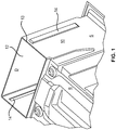
- FIG. 1 shows in a perspective view obliquely from behind the upper portion of an inner container 10 of a refrigerator and / or freezer according to the present invention.
- the inner container has a rear wall R, two oppositely disposed side walls S, a floor, not shown, a top wall D and an open front for removal or for insertion of refrigerated goods.
- FIG. 1 shows, the rear wall R of the inner container 10 is not pulled up to the top wall D, but ends below. Between the upper end region of the rear wall R and the top wall D there is thus an opening 12 on the rear side of the inner container 10.
- This opening 12 extends over the entire width of the inner container, as is made FIG. 1 evident.
- the opening 12 has a peripherally upstanding edge 13, which is used for foam sealing.
- the evaporator module is inserted from the rear side through the opening 12 into the inner container 10 and positioned by means of lateral guide grooves 14.
- the guide grooves 14 extend in the two opposite side walls S in the receiving area for the evaporator module.
- the evaporator module is a no-frost evaporator module, which means that it has at least one fan, by means of which air is conveyed via the evaporator and has at least one defrost heater, by means of which a defrost of the evaporator takes place at regular or specific time intervals.
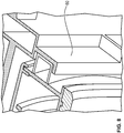
- the evaporator module has an evaporator module housing, which consists of an upper part 21 and a lower part 22.
- the upper part 21 of the evaporator module housing has a rear wall 21 ', which surrounds the edge 13 and which has a groove in which the edge 13 of the opening 12 is arranged.
- the rear wall 21 'of the upper part of the module housing thus serves apart from the normal housing functions, such as the limitation for receiving inner components, etc., as a lid for the foam-tight closing of the large container opening 12.
- the evaporator module housing in addition to the upper part 21, which is firmly foamed, also a lower part 22 which is not foamed and which is movable relative to the upper part 21.
- the housing base 20 can be folded forward or downward.
- the evaporator 30 On the lower housing part 22 are the evaporator 30, the heater 32, a safety limiter for limiting the temperature of the heater and a temperature sensor.
- the reference numeral 34 denotes a cover of the evaporator 30, which rests on top of the evaporator.
- the lower housing part 22 may as FIG. 4 can be folded forwards or downwards.
- connection of the lower housing part 22 relative to the upper housing part 22 can be effected in that the lower part is rotatably mounted by means of a receiving geometry left and right, wherein the pivot points are preferably in the rear region of the housing lower part 22.
- a locking of the housing base 22, for example, by screwing both sides done.
- suction line 40 Since the suction line 40 is foamed, it must remain in the device at a required evaporator replacement.
- the suction line 40 as shown in Figure 5 and 6 can be seen lying outside on the evaporator and led to the rear. Since condensate inevitably precipitates on the suction line during the defrosting process and to prevent the condensate from entering the lower housing part 22, it is collected by means of a channel 35 formed on the cover 34 and directed to a lower water sump 36 from which it is then controlled can conclude.
- the evaporator module according to the invention further comprises a fan assembly, which may be designed as a separate unit.
- This fan assembly is identified by reference numeral 50 in FIG FIG. 7 characterized.
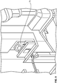
- the fan assembly 50 is held by a geometry similar to a guide rail 60 in the upper part 21 of the evaporator module housing and secured by latching hooks, preferably by two lateral latching hooks in the final position, as is apparent from FIG. 9 evident.
- the latching hooks are identified by the reference numeral 70. They communicate with the upper housing part via a fluid connection and in this way hold the fan module 50.
- the fan assembly can also be removed with the housing lower part 22 closed.
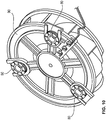
- the fan assembly consists of the fan housing, a front cover with an aperture made of an insulating material, from the fan itself, wherein the motor can be integrated into the impeller and wherein the fan may further comprise a support plate.
- Other ingredients The fan assembly is a lid forming the back, three dampers each, locking pins and plugs.
- damping members 80 are inserted into provided pockets on the carrier or on the support plate 90. This off FIG. 10 apparent arrangement is then slid onto slotted retaining bolts 100 which are arranged on the inside of the cover lid 110.
- the fan is arranged such that it conveys or sucks in air from the front to the rear via the no-frost evaporator module and then distributes the air cooled in this way through an air duct, etc., into the cooled interior.
- the present invention preferably relates to a refrigerator and / or freezer which is designed as a standalone unit. Also, the invention comprises an embodiment of the device according to the invention as a built-in device.
- the no-frost evaporator module is in a preferred embodiment above in the inner container or directly below the ceiling of the inner container and is preferably designed lying, as can also be seen from the figures.
- the air flow is preferably from the front to the rear of the evaporator module, i. comparatively warm air is led over the front of the evaporator module, then cooled and discharged back as cold air.
Description
Die vorliegende Erfindung betrifft ein Kühl- und/oder Gefriergerät mit wenigstens einem Gerätekorpus und mit wenigstens einem gekühlten Innenraum, der zumindest teilweise von einer Ausschäumung umgeben ist und der sich in dem Gerätekorpus befindet, sowie mit wenigstens einem Kältemittelkreislauf, der zumindest ein No-Frost-Verdampfermodul umfasst, das sich in dem gekühlten Innenraum oder in einem mit diesem in Luftströmungsverbindung stehenden Raum befindet.The present invention relates to a refrigerator and / or freezer with at least one appliance body and with at least one cooled interior, which is at least partially surrounded by a foaming and which is located in the device body, and with at least one refrigerant circuit, the at least one no-frost Evaporator module located in the cooled interior or in a space in air flow communication therewith.
Bei aus dem Stand der Technik bekannten Gefriergeräten ist es bekannt, dass der Verdampfer bzw. ein Verdampfermodul nach dem Schäumen des Gerätegehäuses an der Decke des gekühlten Innenraums montiert wird.In known from the prior art freezers, it is known that the evaporator or an evaporator module is mounted after foaming of the device housing to the ceiling of the cooled interior.
Aus dem Stand der Technik sind des Weiteren Geräte bekannt, bei denen sich der Verdampfer auf der Rückseite des gekühlten Innenraums befindet. Die Saugleitung, die vom Verdampfer zum Kompressor des Kältemittelkreislaufes führt, sowie Kabel verlaufen bei bekannten Geräten offen zwischen dem Verdampfer und der Kartonrückwand des Gerätes. Zur Montage wird zunächst das Gerätegehäuse ausgeschäumt und sodann erfolgt der Einbau des Verdampfermoduls im Rahmen der Endmontage. Dabei werden die Versorgungsleitungen, wie beispielsweise Kabel und das Saugrohr des im Innenraum liegenden Verdampfermoduls über Öffnungen nach außen geführt, auf der Rückseite des Gerätes verlegt und mit den entsprechenden Komponenten, wie beispielsweise einer Gerätesteuerung bzw. mit dem Kompressor verbunden. Alle herzustellenden Verbindungen liegen im Außenbereich.Furthermore, devices are known from the prior art in which the evaporator is located on the rear side of the cooled interior. The suction line, which leads from the evaporator to the compressor of the refrigerant circuit, as well as cables run in known devices open between the evaporator and the cardboard rear wall of the device. For assembly is first the device housing is foamed and then the installation of the evaporator module takes place during the final assembly. In this case, the supply lines, such as cables and the suction pipe of the interior of the evaporator module are guided through openings to the outside, laid on the back of the device and connected to the corresponding components, such as a device control or to the compressor. All connections to be made are outdoors.
Das Dokument
Der vorliegenden Erfindung liegt die Aufgabe zugrunde, ein Kühl- und/oder Gefriergerät der eingangs genannten Art dahingehend weiterzubilden, dass eine kostengünstige und fertigungstechnisch sichere Lösung für die Montage des Verdampfermoduls bereitgestellt wird.The present invention has the object of developing a refrigerator and / or freezer of the type mentioned in such a way that a cost-effective and production-safe solution for mounting the evaporator module is provided.
Diese Aufgabe wird durch ein Kühl- und/oder Gefriergerät mit den Merkmalen des Anspruchs 1 gelöst. Danach ist vorgesehen, dass das Verdampfermodul zumindest bereichsweise in der genannten Ausschäumung angeordnet ist.This object is achieved by a refrigerator and / or freezer with the features of claim 1. Thereafter, it is provided that the evaporator module is arranged at least partially in said foaming.
Diese Anordnung ermöglicht eine Vorgehensweise, bei der das Verdampfermodul bereits in der Gerätevormontage, d.h. also vor dem Ausschäumen montiert wird.This arrangement allows a procedure in which the evaporator module is already in the pre-assembly, i. So it is mounted before foaming.
Dadurch ist es möglich, die Saugleitung, die von dem Verdampfer zu dem Kompressor führt sowie die Kapillare, die vom Verflüssiger des Kältemittelkreislaufes zu dem Verdampfer führt direkt in den Schaum zu legen, ohne das zusätzliche Verbindungsstellen entstehen. Die aus dem No-Frost-Verdampfermodul führenden Kabel können ebenfalls im Schaum liegend zu den jeweiligen Schnittstellen beispielsweise am Geräteboden und an der Gerätedecke verlegt werden.This makes it possible to place the suction line, which leads from the evaporator to the compressor and the capillary, which leads from the condenser of the refrigerant circuit to the evaporator directly into the foam without the additional joints arise. The cables leading from the no-frost evaporator module can also be routed in foam to the respective interfaces, for example on the bottom of the device and on the device ceiling.
Vorzugsweise befindet sich das No-Frost-Verdampfermodul, im Folgenden auch einfach als "Verdampfermodul" bezeichnet, im oberen Bereich des gekühlten Innenraums und vorzugsweise direkt unterhalb der Decke des Innenbehälters. Dadurch ist es möglich, die Geräterückwand glatt auszuführen, d.h. ohne Komponenten des Verdampfermoduls und auch ohne Leitungen und Kabel auszuführen, die vom bzw. zu dem Verdampfermodul verlaufen. Aufgrund der Tatsache, dass diese Leitungen vorzugsweise innerhalb der Ausschäumung verlegt werden, kann eine "glatte Geräterückwand", d.h. eine ohne diese Leitungen und Kabel versehende Rückwand des Innenbehälters des Gerätes geschaffen werden.Preferably, the no-frost evaporator module, hereinafter also referred to simply as "evaporator module", is located in the upper region of the cooled interior and preferably directly below the ceiling of the inner container. This makes it possible to perform the back of the device smooth, ie run without components of the evaporator module and without lines and cables that extend from or to the evaporator module. Due to the fact that these lines are preferably laid within the foaming, a "smooth rear panel", ie provided without these cables and cables rear wall of the inner container of the device can be created.
Eine Ausführungsform betrifft des Weiteren ein Kühl- und/oder Gefriergerät mit den Merkmalen des Anspruchs 2.An embodiment further relates to a refrigerator and / or freezer with the features of claim 2.
Danach ist vorgesehen, dass das Verdampfermodul eine Mehrzahl von Komponenten aufweist, von denen eine oder mehrere zu Servicezwecken im Reparaturfall etc. aus dem Verdampfermodul entnehmbar sind. Bei diesen Komponenten kann es sich beispielsweise um den Verdampfer selbst, um die Abtauheizung für den Verdampfer, um einen Sicherheitsbegrenzer sowie auch um Sensoren bzw. Temperaturfühler und um die Ventilatorbaugruppe handeln.Thereafter, it is provided that the evaporator module comprises a plurality of components, one or more of which can be removed from the evaporator module for repair purposes, etc., for service purposes. These components may be, for example, the evaporator itself, the defrost heater for the evaporator, a safety limiter, as well as sensors or temperature sensors and the fan assembly.
Es ist vorgesehen, dass das Verdampfermodul zumindest ein Gehäuse aufweist, von dem sich wenigstens ein Abschnitt in der Ausschäumung bzw. angrenzend an die Ausschäumung befindet. Vorzugsweise handelt es sich dabei um die Rückwand des Gehäuses des Verdampfermoduls.It is provided that the evaporator module has at least one housing, of which at least one section is located in the foaming or adjacent to the foaming. Preferably, this is the rear wall of the housing of the evaporator module.
Das Verdampfermodul ist mehrteilig ausgebildet, beispielsweise aus einem Oberteil und einem relativ dazu bewegbaren Unterteil besteht, sodass das Verdampfermodul geöffnet werden kann und fehlerhafte Bauteile ausgetauscht werden können.The evaporator module is designed in several parts, for example, consists of an upper part and a relatively movable lower part, so that the evaporator module can be opened and faulty components can be replaced.
Da gemäß einer bevorzugten Ausgestaltung der Erfindung die Saugleitung, die die sich vom Verdampfer bis zum Kompressor erstreckt, eingeschäumt ist, muss sie bei einem ggf. erforderlichen Verdampfertausch im Gerät verbleiben. Um die erforderliche Zugänglichkeit beim Trennen und Neuverbinden der Saugleitung und der Kapillare sicherzustellen, ist vorzugsweise vorgesehen, dass die Saugleitung außen am Verdampfer liegend und vorzugsweise nach hinten geführt wird.Since, according to a preferred embodiment of the invention, the suction line, which extends from the evaporator to the compressor, is foamed, it must remain in the device in case of a possibly necessary evaporator replacement. In order to ensure the required accessibility when separating and reconnecting the suction line and the capillary, it is preferably provided that the suction line is guided outside the evaporator and preferably to the rear.
In einer weiteren Ausgestaltung der Erfindung ist vorgesehen, dass das Verdampfermodul eine Ventilatorbaugruppe aufweist, die den Ventilator umfasst, wobei die Ventilatorbaugruppe durch eine formschlüssige oder kraftschlüssige oder sonstige Verbindung an dem Verdampfermodul und vorzugsweise an dessen Gehäuse fixiert ist. Der Ventilator hat die Aufgabe, die in dem Verdampfermodul produzierte Kaltluft in den gekühlten Innenraum des Gerätes zu fördern.In a further embodiment of the invention it is provided that the evaporator module comprises a fan assembly which comprises the fan, wherein the fan assembly is fixed by a positive or non-positive or other connection to the evaporator module and preferably to the housing. The fan has the task to promote the cold air produced in the evaporator module in the cooled interior of the device.
Es ist Erfindungsgemäß vorgesehen, dass der gekühlte Innenraum von wenigsten einem Innenbehälter begrenzt wird, der eine offene Vorderseite zur Entnahme und zum Einlegen von Kühl- bzw. Gefriergut aufweist und der eine Rückseite aufweist, in der eine Öffnung zum Einschieben des Verdampfermoduls in den Innenbehälter vorgesehen ist.It is provided according to the invention that the cooled interior of at least one inner container is limited, which has an open front for removal and insertion of goods to be refrigerated or frozen and which has a rear side, in which an opening for insertion of the evaporator module provided in the inner container is.
Die vorliegende Erfindung betrifft des Weiteren ein Verfahren zur Herstellung des erfindungsgemäßen Kühl- bzw. Gefriergerätes, wobei das Verdampfermodul vor dem Ausschäumen des Gerätes in den gekühlten Innenraum oder in einen damit in Verbindung (zum Luftaustausch) stehenden Raum angeordnet wird und wobei im Anschluss an die Anordnung des Verdampfermoduls die Ausschäumung vorgenommen wird. Das Verdampfermodul wird somit bereits in der Gerätevormontage, d.h. vor dem Schäumprozess montiert. Dadurch kann die Saugleitung mit der Kapillare direkt in den Schaum verlegt werden, ohne dass zusätzliche Verbindungsstellen entstehen bzw. erforderlich sind.The present invention further relates to a method for producing the refrigerator or freezer according to the invention, wherein the evaporator module is placed before the foaming of the device in the cooled interior or in a space communicating therewith (for air exchange) and wherein following the Arrangement of the evaporator module, the foaming is made. The evaporator module is thus already mounted in the device pre-assembly, ie before the foaming process. As a result, the suction line can be laid with the capillary directly into the foam without additional joints being created or required.
Das Verdampfermodul kann durch eine auf der Rückseite des Innenbehälters befindliche Öffnung eingeschoben werden, wobei diese Öffnung nach dem Einschieben des Verdampfermoduls durch ein Gehäuseteil des Verdampfermoduls schaumdicht geschlossen wird. Somit dient das Gehäuse des Verdampfermoduls nicht nur zur Begrenzung bzw. zur Aufnahme der Bauteile des Verdampfermoduls, sondern zusätzlich zum Verschließen der vergleichsweise großen Behälteröffnung, durch die das Verdampfermodul eingeschoben wird.The evaporator module can be inserted through an opening located on the rear side of the inner container, wherein this opening is closed foam-tight after insertion of the evaporator module by a housing part of the evaporator module. Thus, the housing of the evaporator module serves not only to limit or to accommodate the components of the evaporator module, but in addition to closing the comparatively large container opening through which the evaporator module is inserted.
Weitere Einzelheiten und Vorteile der Erfindung werden anhand eines in der Zeichnung dargestellten Ausführungsbeispiels näher erläutert. Es zeigen:
- Figur 1:
- eine perspektivische Ansicht des Innenbehälters von hinten mit der Öffnung zum Einschieben des Vedampfermoduls,
- Figur 2:
- eine perspektivische teilweise geschnittene Ansicht des auf die Öffnung aufgesetzten Gehäuses des Verdampfermoduls,
- Figur 3:
- eine perspektivische Innenansicht auf das Oberteil des Verdampfermodulgehäuses,
- Figur 4:
- eine perspektivische Ansicht des Verdampfermoduls mit Gehäuseoberteil und Gehäuseunterteil, wobei das Gehäuseunterteil nach unten verschwenkt ist,
- Figur 5:
- eine perspektivische Ansicht auf das Verdampfermodul mit außenliegender Saugleitung,
- Figur 6:
- eine perspektivische Ansicht des Verdampfermoduls mit Saugleitung und Ablaufrinne für Kondensat,
- Figur 7:
- eine perspektivische Ansicht der Ventilatorbaugruppe,
- Figur 8:
- eine Detailansicht der Führungsschien im Gehäuseoberteil des Verdampfermoduls zur Aufnahme der Ventilatorbaugruppe,
- Figur 9:
- eine vergrößerte Darstellung von Rasthaken zur Fixierung der Ventilatorbaugruppe,
- Figur 10:
- eine Darstellung des Ventilators mit Dämpfungsteilen,
- Figur 11, 12:
- perspektivische Detailansichten der Ventilatorbaugruppe im Bereich der Dämpfungsteile.
- FIG. 1:
- a perspective view of the inner container from the rear with the opening for insertion of the Vedampfermoduls,
- FIG. 2:
- a perspective partially sectioned view of the mounted on the opening housing of the evaporator module,
- FIG. 3:
- an interior perspective view of the top of the evaporator module housing,
- FIG. 4:
- a perspective view of the evaporator module with upper housing part and lower housing part, wherein the lower housing part is pivoted downward,
- FIG. 5:
- a perspective view of the evaporator module with external suction,
- FIG. 6:
- a perspective view of the evaporator module with suction line and gutter for condensate,
- FIG. 7:
- a perspective view of the fan assembly,
- FIG. 8:
- a detailed view of the guide rails in the upper housing part of the evaporator module for receiving the fan assembly,
- FIG. 9:
- an enlarged view of locking hooks for fixing the fan assembly,
- FIG. 10:
- a representation of the fan with damping parts,
- FIGS. 11, 12:
- perspective detail views of the fan assembly in the area of the damping parts.
Der Innenbehälter weist eine Rückwand R, zwei gegenüber liegend angeordnete Seitenwände S, einen nicht dargestellten Boden, eine Deckwand D sowie eine offene Vorderseite zur Entnahme bzw. zum Einlegen von Kühlgut auf.The inner container has a rear wall R, two oppositely disposed side walls S, a floor, not shown, a top wall D and an open front for removal or for insertion of refrigerated goods.
Wie dies aus
Diese Öffnung 12 erstreckt sich über die gesamte Breite des Innenbehälters, wie dies aus
Die Öffnung 12 weist einen umlaufend hochstehenden Rand 13 auf, der zur Schaumabdichtung genutzt wird.The
Das Verdampfermodul wird von der Rückseite aus durch die Öffnung 12 in den Innenbehälter 10 eingeschoben und mittels seitlicher Führungsnuten 14 positioniert. Die Führungsnuten 14 erstrecken sich in den beiden gegenüberliegenden Seitenwandungen S im Aufnahmebereich für das Verdampfermodul.The evaporator module is inserted from the rear side through the
Das Verdampfermodul ist ein No-Frost-Verdampfermodul, was bedeutet, dass es über zumindest einen Ventilator verfügt, mittels dessen Luft über den Verdampfer gefördert wird sowie zumindest eine Abtauheizung aufweist, mittels derer in regelmäßigen bzw. bestimmten Zeitabständen eine Abtauung des Verdampfers erfolgt.The evaporator module is a no-frost evaporator module, which means that it has at least one fan, by means of which air is conveyed via the evaporator and has at least one defrost heater, by means of which a defrost of the evaporator takes place at regular or specific time intervals.
Das Verdampfermodul weist ein Verdampfermodulgehäuse auf, das aus einem Oberteil 21 und aus einem Unterteil 22 besteht.The evaporator module has an evaporator module housing, which consists of an
Wie dies aus
Für die Schaumdichtheit sorgt ein Labyrinth, das aus dem hochstehenden Behälterrand 13 und einer speziellen Geometrie, vorzugsweise einer Nut an der Rückwand 21 des Gehäuses besteht, wie dies aus
Das Verdampfermodulgehäuse weist außer dem Oberteil 21, das fest eingeschäumt ist, auch ein Unterteil 22 auf, das nicht eingeschäumt ist und das relativ zu dem Oberteil 21 bewegbar ist.The evaporator module housing, in addition to the
Wie dies aus
Das Bezugszeichen 34 kennzeichnet eine Abdeckung des Verdampfers 30, die oben auf dem Verdampfer aufliegt.The
Diese Komponenten ergeben sich insbesondere aus
Damit Teile des Verdampfermoduls im Servicefall getauscht werden können, wurden zwei oder mehr als zwei entnehmbare Baugruppen geschaffen.So that parts of the evaporator module can be exchanged during servicing, two or more than two removable modules have been created.
Das Gehäuseunterteil 22 kann wie aus
In dieser Position können Verdampfer, Heizung, Sicherheitsbegrenzer und - fühler gewechselt werden. Die Anbindung des Gehäuseunterteils 22 relativ zum Gehäuseoberteil 22 kann dadurch erfolgen, dass das Unterteil mittels einer Aufnahmegeometrie links und rechts drehbar gelagert ist, wobei sich die Drehpunkte vorzugsweise im hinteren Bereich des Gehäuseunterteils 22 befinden. Vorne kann eine Arretierung des Gehäuseunterteils 22 z.B. durch beidseitige Verschraubung erfolgen.In this position the evaporator, heating, safety limiters and sensors can be changed. The connection of the
Da die Saugleitung 40 eingeschäumt ist, muss sie bei einem erforderlichen Verdampfertausch im Gerät verbleiben.Since the
Um die erforderliche Zugänglichkeit zum Trennen und Neuverbinden der Saugleitung der Kapillare sicherzustellen, wird die Saugleitung 40 wie aus Figur 5 und 6 ersichtlich außen am Verdampfer liegend und nach hinten geführt. Da sich beim Abtauvorgang zwangsläufig Kondensat an der Saugleitung niederschlägt und um zu verhindern, dass das Kondensat in das Gehäuseunterteil 22 gelangen kann, wird es mittels eines an der Abdeckung 34 angeformten Rinne 35 aufgefangen und auf eine untere Wasserauffangwanne 36 geleitet, von der es dann kontrolliert abschließen kann.In order to ensure the required accessibility for separating and reconnecting the suction line of the capillary, the
Das Verdampfermodul gemäß der Erfindung umfasst des Weiteren eine Ventilatorbaugruppe, die als eigenständige Einheit ausgeführt sein kann. Diese Ventilatorbaugruppe ist mit dem Bezugszeichen 50 in
Die Ventilatorbaugruppe 50 wird durch eine Geometrie ähnlich einer Führungsschiene 60 im Oberteil 21 des Verdampfermodulgehäuses gehalten und durch Rasthaken, vorzugsweise durch zwei seitliche Rasthaken in der finalen Position gesichert, wie dies aus
Die Ventilatorbaugruppe kann auch bei geschlossenem Gehäuseunterteil 22 entnommen werden.The fan assembly can also be removed with the housing
Die Ventilatorbaugruppe besteht aus dem Ventilatorgehäuse, einem Vorderdeckel mit Blendenöffnung aus einem Isolationswerkstoff, aus dem Ventilator selbst, wobei der Motor in das Laufrad integriert sein kann und wobei der Ventilator des Weiteren eine Trägerplatte aufweisen kann. Weitere Bestandteile der Ventilatorbaugruppe sind ein die Rückseite bildender Deckel, je drei Dämpfungsteile, Sicherungsstifte und -stopfen.The fan assembly consists of the fan housing, a front cover with an aperture made of an insulating material, from the fan itself, wherein the motor can be integrated into the impeller and wherein the fan may further comprise a support plate. Other ingredients The fan assembly is a lid forming the back, three dampers each, locking pins and plugs.
Die Montage des Ventilators auf dem rückseitigen Deckel wird anhand der Figuren 10 bis 12 beschrieben.The mounting of the fan on the back cover will be described with reference to FIGS. 10 to 12.
Zunächst werden Dämpfungsteile 80 in vorgesehene Einstecktaschen am Träger bzw. an der Trägerplatte 90 eingeschoben. Diese aus
Schließlich erfolgt eine Sicherung durch Einschieben von Sicherungsstiften, sodass der Träger mit dem daran angeordneten Motor und Laufrad zuverlässig an dem Deckel 110, der die Rückseite der Ventilatorgruppe 50 bildet fixiert ist. Im Betrieb ist der Ventilator derart angeordnet, dass er Luft von vorne nach hinten über das No-Frost-Verdampfermodul fördert bzw. ansaugt und die auf diese Weise gekühlte Luft dann durch einen Luftführungkanal etc. in den gekühlten Innenraum verteilt.Finally, a backup by inserting locking pins, so that the carrier with the motor and impeller arranged thereon is reliably fixed to the
Die vorliegende Erfindung betrifft vorzugsweise ein Kühl- und/oder Gefriergerät das als Standgerät ausgeführt ist. Auch ist von der Erfindung eine Ausführung des erfindungsgemäßen Gerätes als Einbaugerät umfasst.The present invention preferably relates to a refrigerator and / or freezer which is designed as a standalone unit. Also, the invention comprises an embodiment of the device according to the invention as a built-in device.
Wie bereits Eingangs ausgeführt, befindet sich das No-Frost-Verdampfermodul in bevorzugter Ausgestaltung oben im Innenbehälter bzw. direkt unterhalb der Decke des Innenbehälters und ist vorzugsweise liegend ausgeführt, wie dies auch aus den Figuren hervorgeht.As already stated in the introduction, the no-frost evaporator module is in a preferred embodiment above in the inner container or directly below the ceiling of the inner container and is preferably designed lying, as can also be seen from the figures.
Die Luftführung erfolgt vorzugsweise von vorne nach hinten über das Verdampfermodul, d.h. vergleichsweise warme Luft wird vorne über das Verdampfermodul geführt, dann gekühlt und hinten wieder als Kaltluft abgegeben.The air flow is preferably from the front to the rear of the evaporator module, i. comparatively warm air is led over the front of the evaporator module, then cooled and discharged back as cold air.
Claims (9)
- A refrigerator unit and/or a freezer unit having
a unit carcass;
a cooled inner space that is at least partly surrounded by foaming and that is located in the unit carcass; and
a refrigerant circuit that comprises a no-frost evaporator module that is located in the cooled inner space or in a space in communication therewith, wherein the evaporator module is foamed in said foaming, and
wherein the cooled inner space is bounded by an inner container (10) that has an open front side for removing and inserting refrigerated and/or frozen goods,
characterized in that
the cooled inner space has a rear side (R) that has an opening (12) for leading through the evaporator module; and
in that the evaporator module has a housing (21, 22) that is formed in multiple parts and that can be opened. - A refrigerator unit and/or a freezer unit in accordance with claim 1, wherein the evaporator module has a plurality of components of which one or more can be removed from the evaporator module.
- A refrigerator unit and/or a freezer unit in accordance with one of the preceding claims, characterized in that the evaporator module has a housing (21, 22) of which a section is located in the foaming.
- A refrigerator unit and/or a freezer unit in accordance with one of the preceding claims, characterized in that a capillary extending to the evaporator of the evaporator module and a suction line (40) leading away from the evaporator are present that extend at least partly in the foaming.
- A refrigerator unit and/or a freezer unit in accordance with one of the preceding claims, characterized in that the refrigerant circuit has a compressor and a suction line (40) that extends from the evaporator of the evaporator module to the compressor; and in that the section line (40) is arranged at least partially outwardly disposed at the evaporator or at the evaporator module.
- A refrigerator unit and/or a freezer unit in accordance with one of the claims 2 to 5, characterized in that the components of the evaporator module are the evaporator (30) and/or the defrost heating (32) for defrosting the evaporator (30) and/or a temperature sensor and/or a safety delimiter and/or a fan.
- A refrigerator unit and/or a freezer unit in accordance with one of the preceding claims, characterized in that the evaporator module has a fan assembly (50) that comprises the fan, with the fan assembly (50) being fixed to the evaporator module by a shape-matched or force-transmitting connection.
- A method of manufacturing a refrigerator unit and/or a freezer unit in accordance with one of the claims 1 to 7, characterized in that the evaporator module is arranged in the cooled inner space or in a space in communication therewith before the foaming of the unit; and in that the foaming is subsequently carried out.
- A method in accordance with claim 8, characterized in that the evaporator module is inserted through an opening (12) located on the rear side (R) of the inner container (10); and in that this opening (12) is closed in a foam-tight manner by a housing part of the evaporator module after the insertion of the evaporator module.
Applications Claiming Priority (2)
| Application Number | Priority Date | Filing Date | Title |
|---|---|---|---|
| DE102015000519 | 2015-01-19 | ||
| DE102015003138.4A DE102015003138A1 (en) | 2015-01-19 | 2015-03-11 | Fridge and / or freezer |
Publications (2)
| Publication Number | Publication Date |
|---|---|
| EP3045845A1 EP3045845A1 (en) | 2016-07-20 |
| EP3045845B1 true EP3045845B1 (en) | 2019-02-13 |
Family
ID=54936946
Family Applications (1)
| Application Number | Title | Priority Date | Filing Date |
|---|---|---|---|
| EP15202447.7A Active EP3045845B1 (en) | 2015-01-19 | 2015-12-23 | Refrigeration and/or freezer device |
Country Status (1)
| Country | Link |
|---|---|
| EP (1) | EP3045845B1 (en) |
Family Cites Families (3)
| Publication number | Priority date | Publication date | Assignee | Title |
|---|---|---|---|---|
| AU2003286561A1 (en) * | 2003-09-26 | 2005-05-11 | Harold V. Leonard | No-frost and no-drain cooler devices and methods of making |
| ITFI20110018A1 (en) * | 2011-02-02 | 2012-08-03 | C P S I Srl Consulenze Progettazio Ni E Servizi I | REFRIGERATOR APPARATUS. |
| DE102012005248A1 (en) * | 2011-05-10 | 2013-05-16 | Bundy Refrigeration Gmbh | Multichannel Verdampfersytem |
-
2015
- 2015-12-23 EP EP15202447.7A patent/EP3045845B1/en active Active
Non-Patent Citations (1)
| Title |
|---|
| None * |
Also Published As
| Publication number | Publication date |
|---|---|
| EP3045845A1 (en) | 2016-07-20 |
Similar Documents
| Publication | Publication Date | Title |
|---|---|---|
| EP2887838B1 (en) | Cooling unit | |
| EP1719044A2 (en) | Assembly of devices | |
| EP2108907B1 (en) | Cooler, in particular household cooler, with multi-component door guide rail for a door shelf | |
| EP2609380B1 (en) | Refrigerating furniture | |
| EP1957897B1 (en) | Modular arrangement of functional units for a refrigerator and/or freezer and refrigerator and/or freezer comprising a modular arrangement of the functional units | |
| EP1831620A1 (en) | Cooling appliance | |
| EP2529070A1 (en) | Cooling device, in particular for a control cabinet | |
| EP3121042B1 (en) | Cabinet system for a caravan | |
| EP2009376A1 (en) | Evaporator module and cooling or freezing device with such an evaporator module | |
| EP3045845B1 (en) | Refrigeration and/or freezer device | |
| DE1501335A1 (en) | Process for the production of a cooling unit | |
| EP3365623B1 (en) | A household refrigeration appliance with a cooling compartment, a freezing compartment and a pressure equalising valve | |
| DE102015003138A1 (en) | Fridge and / or freezer | |
| DE102016224389A1 (en) | No-frost household refrigeration appliance with separating plate sealing to the rear wall | |
| EP2213966B1 (en) | Temperature conditioning device for a foord transport container | |
| DE102008029138A1 (en) | Refrigerator and/or freezer has aperture frame either with no insertion opening for divider or with insertion opening and closure device in region near at least one of positions in which divider can be inserted | |
| WO2014124631A1 (en) | Combination cable and air channel for air conditioning an electrical enclosure, and a corresponding electrical enclosure | |
| DE102013225649A1 (en) | Domestic refrigeration appliance in a machine room with a carrier shell on which another component is held | |
| DE102015101022B3 (en) | Data Center | |
| EP3447413B1 (en) | Refrigeration and/or freezer device | |
| DE102015014695A1 (en) | Fridge and / or freezer | |
| EP2674705A2 (en) | Refrigeration and/or freezer device | |
| DE102017124425A1 (en) | Refrigerator and / or freezer | |
| EP2461125B1 (en) | Refrigeration and/or freezer device | |
| DE10215272A1 (en) | Quickly installed/dismantled refrigerating facility for refrigerated transport vehicles, has all parts mounted on base plate forming sealed evaporator trough and recesses for holding condenser |
Legal Events
| Date | Code | Title | Description |
|---|---|---|---|
| PUAI | Public reference made under article 153(3) epc to a published international application that has entered the european phase |
Free format text: ORIGINAL CODE: 0009012 |
|
| AK | Designated contracting states |
Kind code of ref document: A1 Designated state(s): AL AT BE BG CH CY CZ DE DK EE ES FI FR GB GR HR HU IE IS IT LI LT LU LV MC MK MT NL NO PL PT RO RS SE SI SK SM TR |
|
| AX | Request for extension of the european patent |
Extension state: BA ME |
|
| STAA | Information on the status of an ep patent application or granted ep patent |
Free format text: STATUS: REQUEST FOR EXAMINATION WAS MADE |
|
| 17P | Request for examination filed |
Effective date: 20170120 |
|
| GRAP | Despatch of communication of intention to grant a patent |
Free format text: ORIGINAL CODE: EPIDOSNIGR1 |
|
| STAA | Information on the status of an ep patent application or granted ep patent |
Free format text: STATUS: GRANT OF PATENT IS INTENDED |
|
| RIC1 | Information provided on ipc code assigned before grant |
Ipc: F25D 23/00 20060101AFI20180710BHEP |
|
| INTG | Intention to grant announced |
Effective date: 20180726 |
|
| GRAS | Grant fee paid |
Free format text: ORIGINAL CODE: EPIDOSNIGR3 |
|
| GRAA | (expected) grant |
Free format text: ORIGINAL CODE: 0009210 |
|
| STAA | Information on the status of an ep patent application or granted ep patent |
Free format text: STATUS: THE PATENT HAS BEEN GRANTED |
|
| AK | Designated contracting states |
Kind code of ref document: B1 Designated state(s): AL AT BE BG CH CY CZ DE DK EE ES FI FR GB GR HR HU IE IS IT LI LT LU LV MC MK MT NL NO PL PT RO RS SE SI SK SM TR |
|
| REG | Reference to a national code |
Ref country code: GB Ref legal event code: FG4D Free format text: NOT ENGLISH |
|
| REG | Reference to a national code |
Ref country code: CH Ref legal event code: EP Ref country code: AT Ref legal event code: REF Ref document number: 1096453 Country of ref document: AT Kind code of ref document: T Effective date: 20190215 |
|
| REG | Reference to a national code |
Ref country code: IE Ref legal event code: FG4D Free format text: LANGUAGE OF EP DOCUMENT: GERMAN |
|
| REG | Reference to a national code |
Ref country code: DE Ref legal event code: R096 Ref document number: 502015007945 Country of ref document: DE |
|
| REG | Reference to a national code |
Ref country code: LT Ref legal event code: MG4D |
|
| REG | Reference to a national code |
Ref country code: NL Ref legal event code: MP Effective date: 20190213 |
|
| PG25 | Lapsed in a contracting state [announced via postgrant information from national office to epo] |
Ref country code: LT Free format text: LAPSE BECAUSE OF FAILURE TO SUBMIT A TRANSLATION OF THE DESCRIPTION OR TO PAY THE FEE WITHIN THE PRESCRIBED TIME-LIMIT Effective date: 20190213 Ref country code: SE Free format text: LAPSE BECAUSE OF FAILURE TO SUBMIT A TRANSLATION OF THE DESCRIPTION OR TO PAY THE FEE WITHIN THE PRESCRIBED TIME-LIMIT Effective date: 20190213 Ref country code: NL Free format text: LAPSE BECAUSE OF FAILURE TO SUBMIT A TRANSLATION OF THE DESCRIPTION OR TO PAY THE FEE WITHIN THE PRESCRIBED TIME-LIMIT Effective date: 20190213 Ref country code: PT Free format text: LAPSE BECAUSE OF FAILURE TO SUBMIT A TRANSLATION OF THE DESCRIPTION OR TO PAY THE FEE WITHIN THE PRESCRIBED TIME-LIMIT Effective date: 20190613 Ref country code: NO Free format text: LAPSE BECAUSE OF FAILURE TO SUBMIT A TRANSLATION OF THE DESCRIPTION OR TO PAY THE FEE WITHIN THE PRESCRIBED TIME-LIMIT Effective date: 20190513 Ref country code: FI Free format text: LAPSE BECAUSE OF FAILURE TO SUBMIT A TRANSLATION OF THE DESCRIPTION OR TO PAY THE FEE WITHIN THE PRESCRIBED TIME-LIMIT Effective date: 20190213 |
|
| PG25 | Lapsed in a contracting state [announced via postgrant information from national office to epo] |
Ref country code: IS Free format text: LAPSE BECAUSE OF FAILURE TO SUBMIT A TRANSLATION OF THE DESCRIPTION OR TO PAY THE FEE WITHIN THE PRESCRIBED TIME-LIMIT Effective date: 20190613 Ref country code: BG Free format text: LAPSE BECAUSE OF FAILURE TO SUBMIT A TRANSLATION OF THE DESCRIPTION OR TO PAY THE FEE WITHIN THE PRESCRIBED TIME-LIMIT Effective date: 20190513 Ref country code: HR Free format text: LAPSE BECAUSE OF FAILURE TO SUBMIT A TRANSLATION OF THE DESCRIPTION OR TO PAY THE FEE WITHIN THE PRESCRIBED TIME-LIMIT Effective date: 20190213 Ref country code: RS Free format text: LAPSE BECAUSE OF FAILURE TO SUBMIT A TRANSLATION OF THE DESCRIPTION OR TO PAY THE FEE WITHIN THE PRESCRIBED TIME-LIMIT Effective date: 20190213 Ref country code: LV Free format text: LAPSE BECAUSE OF FAILURE TO SUBMIT A TRANSLATION OF THE DESCRIPTION OR TO PAY THE FEE WITHIN THE PRESCRIBED TIME-LIMIT Effective date: 20190213 Ref country code: GR Free format text: LAPSE BECAUSE OF FAILURE TO SUBMIT A TRANSLATION OF THE DESCRIPTION OR TO PAY THE FEE WITHIN THE PRESCRIBED TIME-LIMIT Effective date: 20190514 |
|
| REG | Reference to a national code |
Ref country code: ES Ref legal event code: FG2A Ref document number: 2726186 Country of ref document: ES Kind code of ref document: T3 Effective date: 20191002 |
|
| PG25 | Lapsed in a contracting state [announced via postgrant information from national office to epo] |
Ref country code: AL Free format text: LAPSE BECAUSE OF FAILURE TO SUBMIT A TRANSLATION OF THE DESCRIPTION OR TO PAY THE FEE WITHIN THE PRESCRIBED TIME-LIMIT Effective date: 20190213 Ref country code: SK Free format text: LAPSE BECAUSE OF FAILURE TO SUBMIT A TRANSLATION OF THE DESCRIPTION OR TO PAY THE FEE WITHIN THE PRESCRIBED TIME-LIMIT Effective date: 20190213 Ref country code: DK Free format text: LAPSE BECAUSE OF FAILURE TO SUBMIT A TRANSLATION OF THE DESCRIPTION OR TO PAY THE FEE WITHIN THE PRESCRIBED TIME-LIMIT Effective date: 20190213 Ref country code: EE Free format text: LAPSE BECAUSE OF FAILURE TO SUBMIT A TRANSLATION OF THE DESCRIPTION OR TO PAY THE FEE WITHIN THE PRESCRIBED TIME-LIMIT Effective date: 20190213 Ref country code: RO Free format text: LAPSE BECAUSE OF FAILURE TO SUBMIT A TRANSLATION OF THE DESCRIPTION OR TO PAY THE FEE WITHIN THE PRESCRIBED TIME-LIMIT Effective date: 20190213 Ref country code: CZ Free format text: LAPSE BECAUSE OF FAILURE TO SUBMIT A TRANSLATION OF THE DESCRIPTION OR TO PAY THE FEE WITHIN THE PRESCRIBED TIME-LIMIT Effective date: 20190213 |
|
| REG | Reference to a national code |
Ref country code: DE Ref legal event code: R097 Ref document number: 502015007945 Country of ref document: DE |
|
| PG25 | Lapsed in a contracting state [announced via postgrant information from national office to epo] |
Ref country code: SM Free format text: LAPSE BECAUSE OF FAILURE TO SUBMIT A TRANSLATION OF THE DESCRIPTION OR TO PAY THE FEE WITHIN THE PRESCRIBED TIME-LIMIT Effective date: 20190213 Ref country code: PL Free format text: LAPSE BECAUSE OF FAILURE TO SUBMIT A TRANSLATION OF THE DESCRIPTION OR TO PAY THE FEE WITHIN THE PRESCRIBED TIME-LIMIT Effective date: 20190213 |
|
| PLBE | No opposition filed within time limit |
Free format text: ORIGINAL CODE: 0009261 |
|
| STAA | Information on the status of an ep patent application or granted ep patent |
Free format text: STATUS: NO OPPOSITION FILED WITHIN TIME LIMIT |
|
| 26N | No opposition filed |
Effective date: 20191114 |
|
| PG25 | Lapsed in a contracting state [announced via postgrant information from national office to epo] |
Ref country code: SI Free format text: LAPSE BECAUSE OF FAILURE TO SUBMIT A TRANSLATION OF THE DESCRIPTION OR TO PAY THE FEE WITHIN THE PRESCRIBED TIME-LIMIT Effective date: 20190213 |
|
| PG25 | Lapsed in a contracting state [announced via postgrant information from national office to epo] |
Ref country code: TR Free format text: LAPSE BECAUSE OF FAILURE TO SUBMIT A TRANSLATION OF THE DESCRIPTION OR TO PAY THE FEE WITHIN THE PRESCRIBED TIME-LIMIT Effective date: 20190213 |
|
| REG | Reference to a national code |
Ref country code: CH Ref legal event code: PL |
|
| REG | Reference to a national code |
Ref country code: BE Ref legal event code: MM Effective date: 20191231 |
|
| PG25 | Lapsed in a contracting state [announced via postgrant information from national office to epo] |
Ref country code: MC Free format text: LAPSE BECAUSE OF FAILURE TO SUBMIT A TRANSLATION OF THE DESCRIPTION OR TO PAY THE FEE WITHIN THE PRESCRIBED TIME-LIMIT Effective date: 20190213 |
|
| GBPC | Gb: european patent ceased through non-payment of renewal fee |
Effective date: 20191223 |
|
| PG25 | Lapsed in a contracting state [announced via postgrant information from national office to epo] |
Ref country code: IE Free format text: LAPSE BECAUSE OF NON-PAYMENT OF DUE FEES Effective date: 20191223 Ref country code: GB Free format text: LAPSE BECAUSE OF NON-PAYMENT OF DUE FEES Effective date: 20191223 Ref country code: LU Free format text: LAPSE BECAUSE OF NON-PAYMENT OF DUE FEES Effective date: 20191223 |
|
| PG25 | Lapsed in a contracting state [announced via postgrant information from national office to epo] |
Ref country code: CH Free format text: LAPSE BECAUSE OF NON-PAYMENT OF DUE FEES Effective date: 20191231 Ref country code: BE Free format text: LAPSE BECAUSE OF NON-PAYMENT OF DUE FEES Effective date: 20191231 Ref country code: LI Free format text: LAPSE BECAUSE OF NON-PAYMENT OF DUE FEES Effective date: 20191231 |
|
| PGFP | Annual fee paid to national office [announced via postgrant information from national office to epo] |
Ref country code: FR Payment date: 20201228 Year of fee payment: 6 |
|
| PGFP | Annual fee paid to national office [announced via postgrant information from national office to epo] |
Ref country code: IT Payment date: 20201231 Year of fee payment: 6 |
|
| PG25 | Lapsed in a contracting state [announced via postgrant information from national office to epo] |
Ref country code: CY Free format text: LAPSE BECAUSE OF FAILURE TO SUBMIT A TRANSLATION OF THE DESCRIPTION OR TO PAY THE FEE WITHIN THE PRESCRIBED TIME-LIMIT Effective date: 20190213 |
|
| PGFP | Annual fee paid to national office [announced via postgrant information from national office to epo] |
Ref country code: ES Payment date: 20210108 Year of fee payment: 6 |
|
| PG25 | Lapsed in a contracting state [announced via postgrant information from national office to epo] |
Ref country code: HU Free format text: LAPSE BECAUSE OF FAILURE TO SUBMIT A TRANSLATION OF THE DESCRIPTION OR TO PAY THE FEE WITHIN THE PRESCRIBED TIME-LIMIT; INVALID AB INITIO Effective date: 20151223 Ref country code: MT Free format text: LAPSE BECAUSE OF FAILURE TO SUBMIT A TRANSLATION OF THE DESCRIPTION OR TO PAY THE FEE WITHIN THE PRESCRIBED TIME-LIMIT Effective date: 20190213 |
|
| REG | Reference to a national code |
Ref country code: AT Ref legal event code: MM01 Ref document number: 1096453 Country of ref document: AT Kind code of ref document: T Effective date: 20201223 |
|
| PG25 | Lapsed in a contracting state [announced via postgrant information from national office to epo] |
Ref country code: AT Free format text: LAPSE BECAUSE OF NON-PAYMENT OF DUE FEES Effective date: 20201223 |
|
| PG25 | Lapsed in a contracting state [announced via postgrant information from national office to epo] |
Ref country code: MK Free format text: LAPSE BECAUSE OF FAILURE TO SUBMIT A TRANSLATION OF THE DESCRIPTION OR TO PAY THE FEE WITHIN THE PRESCRIBED TIME-LIMIT Effective date: 20190213 |
|
| PG25 | Lapsed in a contracting state [announced via postgrant information from national office to epo] |
Ref country code: FR Free format text: LAPSE BECAUSE OF NON-PAYMENT OF DUE FEES Effective date: 20211231 |
|
| PG25 | Lapsed in a contracting state [announced via postgrant information from national office to epo] |
Ref country code: IT Free format text: LAPSE BECAUSE OF NON-PAYMENT OF DUE FEES Effective date: 20211223 |
|
| REG | Reference to a national code |
Ref country code: ES Ref legal event code: FD2A Effective date: 20230224 |
|
| PG25 | Lapsed in a contracting state [announced via postgrant information from national office to epo] |
Ref country code: ES Free format text: LAPSE BECAUSE OF NON-PAYMENT OF DUE FEES Effective date: 20211224 |
|
| PGFP | Annual fee paid to national office [announced via postgrant information from national office to epo] |
Ref country code: DE Payment date: 20221229 Year of fee payment: 8 |
|
| PGFP | Annual fee paid to national office [announced via postgrant information from national office to epo] |
Ref country code: DE Payment date: 20231221 Year of fee payment: 9 |