EP3045834B1 - Klimaanlage - Google Patents
Klimaanlage Download PDFInfo
- Publication number
- EP3045834B1 EP3045834B1 EP16151084.7A EP16151084A EP3045834B1 EP 3045834 B1 EP3045834 B1 EP 3045834B1 EP 16151084 A EP16151084 A EP 16151084A EP 3045834 B1 EP3045834 B1 EP 3045834B1
- Authority
- EP
- European Patent Office
- Prior art keywords
- panel
- connector
- base
- shroud
- air conditioner
- Prior art date
- Legal status (The legal status is an assumption and is not a legal conclusion. Google has not performed a legal analysis and makes no representation as to the accuracy of the status listed.)
- Active
Links
- 238000007664 blowing Methods 0.000 claims description 84
- 230000008878 coupling Effects 0.000 claims description 40
- 238000010168 coupling process Methods 0.000 claims description 40
- 238000005859 coupling reaction Methods 0.000 claims description 40
- 238000007599 discharging Methods 0.000 claims description 6
- 238000003780 insertion Methods 0.000 claims description 4
- 230000037431 insertion Effects 0.000 claims description 4
- 229910052751 metal Inorganic materials 0.000 description 8
- 239000002184 metal Substances 0.000 description 8
- 239000000758 substrate Substances 0.000 description 8
- 238000000465 moulding Methods 0.000 description 7
- 239000003507 refrigerant Substances 0.000 description 4
- 239000000463 material Substances 0.000 description 3
- 238000000034 method Methods 0.000 description 3
- 238000000151 deposition Methods 0.000 description 2
- 230000000694 effects Effects 0.000 description 2
- 230000008569 process Effects 0.000 description 2
- 229920003002 synthetic resin Polymers 0.000 description 2
- 239000000057 synthetic resin Substances 0.000 description 2
- -1 Polyethylene phthalate Polymers 0.000 description 1
- 239000000853 adhesive Substances 0.000 description 1
- 230000001070 adhesive effect Effects 0.000 description 1
- 238000004378 air conditioning Methods 0.000 description 1
- 239000002775 capsule Substances 0.000 description 1
- 230000008859 change Effects 0.000 description 1
- 239000011248 coating agent Substances 0.000 description 1
- 238000000576 coating method Methods 0.000 description 1
- 238000005520 cutting process Methods 0.000 description 1
- 229910052738 indium Inorganic materials 0.000 description 1
- APFVFJFRJDLVQX-UHFFFAOYSA-N indium atom Chemical compound [In] APFVFJFRJDLVQX-UHFFFAOYSA-N 0.000 description 1
- 238000004519 manufacturing process Methods 0.000 description 1
- 230000007246 mechanism Effects 0.000 description 1
- 230000001151 other effect Effects 0.000 description 1
- 238000007639 printing Methods 0.000 description 1
- 238000000926 separation method Methods 0.000 description 1
- XLYOFNOQVPJJNP-UHFFFAOYSA-N water Substances O XLYOFNOQVPJJNP-UHFFFAOYSA-N 0.000 description 1
Images






Classifications
-
- F—MECHANICAL ENGINEERING; LIGHTING; HEATING; WEAPONS; BLASTING
- F24—HEATING; RANGES; VENTILATING
- F24F—AIR-CONDITIONING; AIR-HUMIDIFICATION; VENTILATION; USE OF AIR CURRENTS FOR SCREENING
- F24F13/00—Details common to, or for air-conditioning, air-humidification, ventilation or use of air currents for screening
- F24F13/20—Casings or covers
-
- F—MECHANICAL ENGINEERING; LIGHTING; HEATING; WEAPONS; BLASTING
- F24—HEATING; RANGES; VENTILATING
- F24F—AIR-CONDITIONING; AIR-HUMIDIFICATION; VENTILATION; USE OF AIR CURRENTS FOR SCREENING
- F24F1/00—Room units for air-conditioning, e.g. separate or self-contained units or units receiving primary air from a central station
- F24F1/0007—Indoor units, e.g. fan coil units
- F24F1/0011—Indoor units, e.g. fan coil units characterised by air outlets
-
- F—MECHANICAL ENGINEERING; LIGHTING; HEATING; WEAPONS; BLASTING
- F24—HEATING; RANGES; VENTILATING
- F24F—AIR-CONDITIONING; AIR-HUMIDIFICATION; VENTILATION; USE OF AIR CURRENTS FOR SCREENING
- F24F1/00—Room units for air-conditioning, e.g. separate or self-contained units or units receiving primary air from a central station
- F24F1/0007—Indoor units, e.g. fan coil units
- F24F1/0035—Indoor units, e.g. fan coil units characterised by introduction of outside air to the room
-
- F—MECHANICAL ENGINEERING; LIGHTING; HEATING; WEAPONS; BLASTING
- F24—HEATING; RANGES; VENTILATING
- F24F—AIR-CONDITIONING; AIR-HUMIDIFICATION; VENTILATION; USE OF AIR CURRENTS FOR SCREENING
- F24F1/00—Room units for air-conditioning, e.g. separate or self-contained units or units receiving primary air from a central station
- F24F1/0007—Indoor units, e.g. fan coil units
- F24F1/0041—Indoor units, e.g. fan coil units characterised by exhaustion of inside air from the room
-
- F—MECHANICAL ENGINEERING; LIGHTING; HEATING; WEAPONS; BLASTING
- F24—HEATING; RANGES; VENTILATING
- F24F—AIR-CONDITIONING; AIR-HUMIDIFICATION; VENTILATION; USE OF AIR CURRENTS FOR SCREENING
- F24F1/00—Room units for air-conditioning, e.g. separate or self-contained units or units receiving primary air from a central station
- F24F1/0007—Indoor units, e.g. fan coil units
- F24F1/0043—Indoor units, e.g. fan coil units characterised by mounting arrangements
- F24F1/005—Indoor units, e.g. fan coil units characterised by mounting arrangements mounted on the floor; standing on the floor
-
- F—MECHANICAL ENGINEERING; LIGHTING; HEATING; WEAPONS; BLASTING
- F24—HEATING; RANGES; VENTILATING
- F24F—AIR-CONDITIONING; AIR-HUMIDIFICATION; VENTILATION; USE OF AIR CURRENTS FOR SCREENING
- F24F13/00—Details common to, or for air-conditioning, air-humidification, ventilation or use of air currents for screening
- F24F13/20—Casings or covers
- F24F2013/205—Mounting a ventilator fan therein
-
- F—MECHANICAL ENGINEERING; LIGHTING; HEATING; WEAPONS; BLASTING
- F24—HEATING; RANGES; VENTILATING
- F24F—AIR-CONDITIONING; AIR-HUMIDIFICATION; VENTILATION; USE OF AIR CURRENTS FOR SCREENING
- F24F13/00—Details common to, or for air-conditioning, air-humidification, ventilation or use of air currents for screening
- F24F13/20—Casings or covers
- F24F2013/207—Casings or covers with control knobs; Mounting controlling members or control units therein
-
- F—MECHANICAL ENGINEERING; LIGHTING; HEATING; WEAPONS; BLASTING
- F24—HEATING; RANGES; VENTILATING
- F24F—AIR-CONDITIONING; AIR-HUMIDIFICATION; VENTILATION; USE OF AIR CURRENTS FOR SCREENING
- F24F2221/00—Details or features not otherwise provided for
- F24F2221/36—Modules, e.g. for an easy mounting or transport
Definitions
- the present invention relates at an air conditioner, and more particularly, to an air conditioner that can be easily assembled in a simple structure and has high efficiency.
- An air conditioner is an apparatus that makes an interior pleasant by admitting air through an air intake port, changes temperature, humidity, and cleanness of the air, and then discharge the air into the interior through an air discharge port.
- an air discharge port may be formed at the front, and an air-conditioning unit such as a heat exchanger or a filter that can change temperature, humidity, cleanness of air and a blower for blowing air may be disposed therein.
- an air-conditioning unit such as a heat exchanger or a filter that can change temperature, humidity, cleanness of air and a blower for blowing air
- Home air conditioner is generally a separate type air conditioner in which an indoor heat exchanger and an indoor blower are disposed in an indoor unit, an outdoor heat exchanger, an outdoor blower, and a compressor are disposed in an outdoor unit, and the indoor unit and the outdoor unit are connected by a refrigerant pipe, and this separation type is classified into a wall-mounting type and a stand type.
- the KR 101 385 289 B1 describes an air conditioner.
- the air conditioner includes a suction body having an air suction opening, a heat exchanger through which air sucked through the air suction opening passes, an aroma case having a space through which air passes and an air discharge opening through which the air in the space is discharged, a blower for drawing in air through the air suction opening and blowing the sucked air into the space after the air passes the heat exchanger, an aroma kit to which an aroma capsule is attached or detached and accommodated in the space to be moved, and an aroma kit moving mechanism for moving the aroma kit to a position of shielding the air discharge opening or a position of opening the air discharge opening.
- An object of the present invention is to provide an air conditioner that can be easily assembled and has high efficiency with a simple structure.
- the object is solved by the features of the independent claim.
- an air conditioner preferably includes a base rear panel forming a lower rear external appearance and having an internal space therein, a body rear panel coupled to the upper portion of the base rear panel and forming an upper rear external appearance, the body rear panel has an inlet for admitting air, a connector coupled to an inside of the base rear panel, a base front panel coupled to the connector and forming a lower front external appearance, and a body front panel forming an upper front external appearance and having an outlet for discharging air, a lower end of the body front panel coupled to the base front panel and a lateral side of the body front panel coupled to the body rear panel.
- the air conditioner further comprises a blowing module for discharging air admitted through the inlet to the outlet, and a shroud panel for guiding air admitted through the inlet to the blowing module, a lower end of the shroud panel coupled to the connector and a lateral side of the shroud panel coupled to the body rear panel.
- the air conditioner comprises a guide panel that may be coupled to the shroud panel to guide air from the blowing module to the outlet.
- the blowing module is disposed between the shroud panel and the guide panel and is coupled to the guide panel.
- the guide panel may have a guide hole through which air from the blowing module may be discharged.
- the air conditioner may further comprise a door unit rotatably coupled to the guide panel for closing the outlet and the guide hole.
- the lower end of the shroud panel may be coupled to the upper end of the connector, and the shroud panel may have a shroud flange protruding downward and coupled to the front side of the connector.
- the shroud panel may have a shroud hook protruding at a lateral side of the shroud panel, and the body rear panel may have a shroud hook coupling portion on an inner side of the body rear panel, to lock the shroud hook.
- the base rear panel may have a connector receiving portion recessed down at a portion of the inner bottom of the base rear panel to receive the lower portion of the connector.
- the base rear panel may have a connector locking plate protruding forward from an inner side of the base rear panel, wherein the connector may have a locking plate receiving portion on a lateral side of the connector to receive the connector locking plate, and a locking plate coupling portion is formed at the locking plate receiving portion, a front end of the connector locking plate fits in the locking plate coupling portion.
- the base rear panel may have a connector insertion portion on an inner side of the base rear panel, a portion of the connector may be inserted into the connector insertion portion.
- the base front panel may have a base front hook protruding on an inner side of the base front panel, and the connector may have a base front hook coupling portion to lock the base front hook.
- the body front panel may have a body front hook protruding downward on a inner lateral side of the body front panel, and the body rear panel may have a body front hook coupling portion on an outer lateral side of the body rear panel, the body front hook may be inserted into the body front hook coupling portion from above.
- the body front panel may have a body front flange protruding at a lower end of the body front panel, and the base front panel may have a body front flange coupling portion protruding rearward on an upper inner side of the base front panel to couple to the body front flange.
- the connector may have a connector bolt inserting portion in which a connector bolt for jointing the connector and the base rear panel may be inserted.
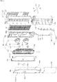
- FIG. 1 is a perspective view showing an air conditioner according to an embodiment of the present invention and FIG. 2 is an exploded perspective view of the air conditioner shown in FIG. 1 .
- An air conditioner includes a base rear panel 110 forming a lower rear external appearance and having an internal space therein, , a body rear panel 150 coupled to the top of the base rear panel 110, forming an upper rear external appearance, and having an inlet 151a for admitting air, a connector 130 coupled to an inside of the base rear panel 110, a base front panel 120 coupled to the connector 130 and forming a lower front external appearance, and a body front panel 190 forming an upper front external appearance and having an outlet for discharging air, a lower end of the body front panel coupled to the base front panel 120, a lateral side of the body front panel coupled to the body rear panel 150.
- the base rear panel 110 forms the lower rear external appearance of the air conditioner and supports the air conditioner by being supported on the floor.
- the base rear panel 110 has a polygonal shape with the front open to open the internal space.
- the rear side of the base rear panel 110 may be curved.
- the bottom of the base rear panel 110 is placed on the floor.
- the connector 130 is connected to an inner lateral side of the base rear panel 110.
- An electronic box (not shown) keeping a circuit device for controlling the air conditioner and other electronic parts is disposed in the internal space of the base rear panel 110.
- the base front panel 120 is disposed ahead of the base rear panel 110.
- the body rear panel 150 is disposed over the base rear panel 110.
- the connector 130 is connected to an inner lateral side of the base rear panel 110.
- the connector 130 is formed in a vertically long column shape.
- the connector 130 may include a left connector 130-1 coupled to the left inner lateral side of the base rear panel 110 and a right connector 130-2 coupled to the right inner lateral side of the base rear panel 110.
- the left connector 130-1 and the right connector 130-2 are symmetric to each other at the left and right lateral sides.
- the connector 130 supports the shroud panel 160 equipped with a blowing module 140 and a guide panel 170 by increasing the strength of the base rear panel 110.
- the bottom and a lateral side of the connector 130 are coupled to the base rear panel 110.
- the shroud panel 160 is coupled to the upper portion of the connector 130.
- the base front panel 120 is coupled to the front of the connector 130.
- the body rear panel 150 is coupled to the upper portion of the base rear panel 110 and forms the upper rear external appearance of the air conditioner.
- the body rear panel 150 has a polygonal shape with the front and bottom open to open to form a space therein.
- the body rear panel 150 has the inlet 151a for admitting the air in an indoor where the air conditioner is installed.
- the inlet 151a is formed through the rear side of the body rear panel 150.
- the body rear panel 150 includes a body rear panel body 151 having the inlet 151a at the rear side and a rear panel filter unit 152 mounted on the rear side of the body rear panel body 151 and covering the inlet 151a.
- the rear panel filter unit 152 filters air admitted into the inlet 151a.
- the rear panel filter unit 152 may be disposed on the outer of the rear side of the body rear panel body 151.
- the shroud panel 160 is coupled to the front of the body rear panel 150.
- the base rear panel 110 is coupled to the lower portion of the body rear panel 150.
- the indoor heat exchanger 10 is disposed inside the body rear panel 150.
- the indoor heat exchanger 10 is disposed between the body rear panel 150 and the shroud panel 160 and allows a refrigerant to exchange heat with the air admitted into the inlet 151a of the body rear panel 150.
- the air that has been cooled or heated by exchanging heat with the refrigerant through the indoor heat exchanger 10 flows to the shroud panel 160.
- the indoor heat exchanger 10 includes tubes through which the refrigerant flows and fins for exchanging heat with air.
- the blowing module 140 admits air into the inlet 151a of the body rear panel 150 and discharges air to the outlet 190a of the body front panel 190.
- the air admitted into the inlet 151a passes through the indoor heat exchanger 10 and then flows through shroud holes 160a of the shroud panel 160.
- the air from the blowing module 140 is discharged to the outlet 190a of the body front panel 190 through guide holes 170a of the guide panel 170.
- a plurality of blowing modules 140 may be provided and two blowing modules 140 are provided in this embodiment. Two blowing modules 140 are vertically arranged. Two blowing modules 140 are arranged to correspond to two shroud holes 160a of the shroud panel 160. Two blowing modules 140 are vertically coupled to the rear side of the guide panel 170.
- the blowing modules 140 each include a blowing motor 142 generating torque, a blowing motor bracket 143 for coupling the blowing motor 142 to the rear side of the guide panel 170, and a blowing fan 141 rotated by the blowing motor 142 to blow air.
- the blowing fan 141 may be a centrifugal fan that axially admits air and radially discharges air through the lateral side.
- the blowing fan 141 is arranged such that the air suction direction faces the shroud holds 160a of the shroud panel 160.
- the air discharged through the lateral side of the blowing fan 141 flows forward by the shroud panel 160 and then passes through the guide holes 170a of the guide panel 170.
- a plurality of blowing fans 141 is provided and arranged to correspond to a plurality of shroud holes 160a.
- the shroud panel 160 guides the air that is admitted into the inlet 151a of the body rear panel 150 and flows to the blowing module 140.
- the shroud panel 160 has the shroud holes 160a through which the air, which is admitted into the inlet 151a and flows to the blowing module 140 in the indoor heat exchanger 10, passes.
- a plurality of shroud holes 160a may be provided to correspond to a plurality of blowing module 140, and in the embodiment, two shroud holes 160a are vertically formed to corresponding to two blowing module 140.
- the portions around the shroud holes 160a of the shroud panel 160 are formed in the shape of a dome, the blowing modules 140 are disposed therein, and air from the blowing modules 140 is guided forward.
- the lower end of the shroud panel 160 is coupled to the upper end of the connector 130.
- the body rear panel 150 is coupled to the rear portion of the shroud panel 160.
- the guide panel 170 is coupled to the front portion of the shroud panel 160.
- the guide panel 170 guides the air from the blowing module 140 to the outlet 190a.
- the guide panel 170 has the guide holes 170a through which the air, which flows through the outlet 190a from the blowing module 140, passes.
- a plurality of guide holes 170a is provided and two guide holes 170a are vertically elongated and disposed at the left and right sides of a center line C.
- the guide holes 170a become narrower toward the upper ends and the lower ends.
- the upper ends and the lower ends of the guide holes 170a are curved toward the center line C.
- the guide hole 170a is closed by the door unit 180, and when there is a plurality of guide holes 170a, a plurality of door units 180 is provided to close them, respectively.
- the blowing module 140 is mounted on the rear side of the guide panel 170.
- two blowing modules 140 are coupled and vertically arranged to the rear side of the guide panel 170.
- the door units 180 are disposed ahead of the guide panel 170.
- two door units 180 are arranged to at the left and right sides of the front of the guide panel 170.
- the guide panels 170 are at least partially curved such that the door units 180 can rotate and slide along the guide panel 170.
- two door units 180 are disposed at the left and right sides and the guide panel 170 is curved at the left and right sides of the front with respect to a vertical center line. That is, the horizontal cross-section of the guide panel 170 may be formed partially in an arc shape protruding forward at the left and right sides with respect to the center line.
- the guide panel 170 is coupled to the shroud panel 160 with the blowing module 140 therebetween, thereby forming one unit.
- the guide panel 170, blowing module 140, and shroud panel 160 may be referred to as a blowing unit 90, in combination. That is, the blowing unit 90 includes a guide panel 170, a blowing module 140, and the shroud panel 160.
- the door unit 180 closes the guide hole 170a and the outlet 190a.
- the door unit 180 is rotatably coupled to the blowing unit 90.
- the door unit 180 is rotatably coupled to the guide panel 170 or the shroud panel 160 of the blowing unit 90, and in this embodiment, the door unit 180 is rotatably coupled to the guide panel 170.
- a portion of the door unit 180 opens or closes the guide hole 170a by sliding on the front of the guide panel 170.
- a portion of the door unit 180 opens or closes the outlet 190a by sliding on the rear of the body front panel 190. That is, a portion of the door unit 180 simultaneously opens or closes the guide hole 170a and the outlet 190a by sliding between the guide panel 170 and the body front panel 190.
- the base front panel 120 forms the lower front external shape of the air conditioner.
- the base panel 120 is coupled to the connector 130 and covers the open front of the base rear panel 110.
- the base front panel 120 is a curved plate.
- the rear side of the base front panel 120 is coupled to the connector 130 and the upper end of the base front panel 120 is coupled to the body front panel 190.
- the base front panel 190 forms the upper front external shape of the air conditioner.
- the outlet 190a for discharging the air passing through the guide hole 170a by the blowing module 140 is formed at the body front panel 190.
- the outlet 190a is formed to correspond to the guide hole 170a.
- two outlets 190a are vertically elongated and formed to correspond to two guide holes 170a, at the left and right sides of the center line C.
- the outlets 190a are formed such that the upper ends and lower ends are curved toward a vertical center line.
- the outlets 190a are tapered toward the upper ends and lower ends.
- the outlets 190a are closed by the door units 180.
- the body front panel 190 is a curved plate. The lower end of the body front panel 190 is coupled to the base front panel 120 and the lateral side is coupled to the body rear panel 150.
- a control hole 190b that is open to expose a portion of a control module 200 is formed at the body front panel 190.
- the control hole 190b may be formed in a circle.
- the control module 200 receives instructions from a user or shows the operational state of the air conditioner.
- the control module 200 is coupled to the rear side of the body front panel 190 with a portion exposed to the outside through the control hole 190b.
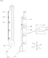
- FIG. 3 is a perspective view showing a connector of an air conditioner according to an embodiment of the present invention
- FIG. 4 is a perspective view showing a base rear panel of an air conditioner according to an embodiment of the present invention.
- the connector 130 has a connector base 139 that is formed at the lower portion and coupled to the bottom of the base rear panel 110, locking plate receiving portions 131 that are formed by recessing inward portions of the side facing the inside of the base rear panel 110, locking plate coupling portions 132 that protrude rearward and are spaced from the locking plate receiving portions 131 at the front ends of the locking plate receiving portions 131, base front hook coupling portion 133 that are open to couple the base front panel 120, and connector bolt inserting portions 135 that are open to insert connector bolts 136 for jointing the connector 130 and the base rear panel 110.
- the connector 130 includes two parts, that is, the left connector 130-1 and the right connector 130-2, and the connector base 139, locking plate receiving portions 131, locking plate coupling portions 132, base front hook coupling portions 133, and connector bolt inserting portions 135 are formed correspond to each other at the left and right connectors.
- the base rear panel 110 has a connector receiving portion 112 formed by cutting a portion of the bottom to receive the lower portion of the connector 130, a connector locking plate 113 that is formed in the shape of a cantilever protruding forward from the inner side, a connecting inserting portion 114 that is formed on the inner side to insert a portion of the connector, a connector bolt coupling portion 115 in which the connector bolt 136 is inserted, and a drain portion 119 (see Fig. 4 ) that collects water condensed through the indoor heat exchanger 10.
- the connector base 139 has a portion of which the cross-sectional area increases as it goes down. The bottom and a portion of the connector base 139 are inserted in the connector receiving portion 112.
- the locking plate receiving portions 131 are vertically arranged on the side facing the inner side of the base rear panel 110 to receive the connector locking plates 113.
- the connector locking plates 113 are vertically arranged on both inner sides of the base rear panel 110 to correspond to the locking plate receiving portions 131.
- the front end of the connector locking plate 113 protrude forward from the inner side of the base rear panel 110 and the front end of the connector locking plate 113 is fitted in the locking plate coupling portion 132.
- the connector inserting portion 114 is formed in a U-shape to cover a portion of the lateral sides and rear side of the connector 130.
- the connector inserting portions 114 may be formed on both inner sides of the base rear panel 110.
- a connector bolt coupling portion 115 is formed at least one of the connecting inserting portions 114 and the connector bolt 136 inserts in the connector bolt coupling portion 115.
- the base front hook coupling portions 133 are arranged vertically on the front side of the connector 130.
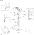
- FIG. 5 is an assembly view showing a shroud panel of an air conditioner according to an embodiment of the present invention
- FIG. 6 is an assembly view showing a body front panel of an air conditioner according to an embodiment of the present invention
- FIG. 7 is an assembly view showing a base front panel of an air conditioner according to an embodiment of the present invention.
- the shroud panel 160 has shroud hooks 165 protruding downward at a lateral side and a shroud flange 166 protruding downward at the lower end.
- the shroud hooks 165 are arranged vertically at both lateral sides of the shroud panel 160.
- the shroud hooks 165 are locked to shroud hook coupling portions 155 that will be described below.
- Two shroud flanges 166 are formed at both lateral sides of the lower end of the shroud panel 160.
- the shroud flanges 166 overlap a portion of the upper front end of each of the left connector 130-1 and the right connector 130-2.
- a shroud bolt inserting portion 137 is formed at the upper end of the connector 130 and the shroud bolt insert in the shroud bolt inserting portion 137.
- shroud hook coupling portions 155 are formed in the inner side to lock the shroud hooks 165 and body front hook coupling portions 157 are formed on the outer lateral side to lock the body front hooks 193 (see Fig. 9 ).
- the shroud hook coupling portions 155 may be formed in the shape of a hole or a hook.
- the body front hook coupling portions 157 may be formed in the shape of a hole or a hook.
- the lower portion of the body rear panel 150 covers the drain portion 119, so the body rear panel 150 and the base rear panel 110 are coupled.
- the shroud hook coupling portions 155 are vertically arranged on both inner sides of the body rear panel 150 to correspond to the shroud hooks 165.
- the body front hook coupling portions 157 are vertically arranged on both outer sides of the body rear panel 150.
- base front hooks 123 that protrude rearward to be locked to the base front hook coupling portions 133 of the connector 130 are formed on the inner side and body front flange coupling portions 125 coupled to the body front flange 195 protrude rearward on the inner side of the upper end.
- the base front hooks 123 are vertically arranged to correspond to the base front hook coupling portions 133 at both inner sides of the base front panel 120. As in FIG. 7 , the base front hooks 123 are locked to the base front hook coupling portions 133, so the base front panel 120 is coupled to the connector 130.
- the body front panel 190 has the body front flange 195 protruding downward at the lower end. As in FIG. 6 , the body front flange 195 is partially recessed rearward so that the body front flange coupling portion 125 is fitted therein.
- FIG. 8 is a perspective view showing a door unit of an air conditioner according to an embodiment of the present invention
- FIG. 9 is an exploded perspective view showing some parts of an air conditioner according to an embodiment of the present invention
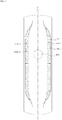
- FIG. 10 is a front view showing a guide panel of an air conditioner according to an embodiment of the present invention
- FIG. 11 is a front view showing a body front panel of an air conditioner according to an embodiment of the present invention.
- the door unit 180 includes a left door unit 180-1 and a right door unit 180-2.
- the left door unit 180-1 closes the left outlet 190a-1 and the left guide hole 170a-1 and the right door unit 180-2 closes the right outlet 190a-2 and the right guide hole 170a-2.
- the door unit 180 include door panels 181 that open or close the outlet 190a and the guide hole 170a by moving between the guide panel 170 and the body front panel 190, door ribs 185 that protrude forward from the door panels 181, door actuating arms 182 projecting rearward from the door panels 181 like a cantilever, door rotating arms 183 projecting rearward from the door panels 181 like a cantilever, and door guide plates 184 that protrude downward from the door panels 181.
- the door panels 181 are panels vertically elongated.
- the door panels 181 are formed to correspond to the guide holes 170a to completely cover the guide hole 170a.
- the door panels 181 become narrower toward the upper ends and the lower ends.
- the door panels 181 are curved toward a center line C of the guide panel 170 at the upper ends and the lower ends.
- the door panel opens or closes the outlet 190a and the guide hole 170a by sliding between the guide panel 170 and the body front panel 190.
- the door panel 181 may be disposed between the guide panel 170 and the body front panel 190 without being in direct contact with the guide panel 170 and the body front panel 190.
- the door panel 181 may be formed in an arc shape at a portion of the horizontal cross-section.
- the door unit 180 rotates about the rear ends of the door actuating arms 182 and the door rotating arms 183, so the door panels 181 is rotated substantially in an arc shape when opening or closing the outlet 190a and the guide hole 170a.
- the door ribs 185 protrude forward from the door panels 181 to prevent the door panels 181 from coming in direct contact with the body front panel 190.
- the door ribs 185 are vertically arranged on the front side of the door panels 181.
- the body front panel 190 has door rib guides 197 formed in an arc shape with the rear sides in contact with the door ribs 185.
- the door rib guides 197 may be vertically arranged to correspond to the door ribs 185.
- the door actuating arm 182 protrudes rearward from the door panel 181 like a cantilever.
- the door actuating arm 182 is formed in an arc shape that becomes narrower toward the rear end.
- the rear end of the door actuating arm 182 is directly connected to a door actuating unit 189 (see Fig. 14 ) and rotated by the door actuating unit 189.
- the door actuating arm 182 is rotatably placed of coupled to a door actuating arm support 172 of the guide panel 170 that will be described below.
- the door actuating arms 182 may be disposed at the upper end and the lower end of the door panel 181.
- the door rotating arm 183 extends rearward from the door panel 181 like a cantilever.
- the rear end of the door rotating arm 183 is rotatably coupled to the door rotating arm support 173 of the guide panel 170 that will be described below.
- a plurality of door actuating arms 182 is provided, a plurality of door rotating arms 183 is disposed between the door actuating arms 182.
- Door guide fins 184 protrude downward from the door panel 181 and spaced rearward from the door panel 181.
- the door guide fins 184 are inserted in door guide rails 174 of the guide panel 170 that will be described below and slide in an arc shape along the door guide rails 174.
- the door guide fins 184 may be arranged vertically on the door panel 181.
- the door guide fins 184 may be disposed between the door actuating arm 182 and the door rotating arm 183.
- the body front panel 190 according to an embodiment of the present invention has body front hooks 193 protruding downward on the inner lateral side and the door rib guides 197 on the rear side.
- the body front hooks 193 are inserted in the body front hook coupling portions 157 from above, so the body front panel 190 and the body rear panel 150 are coupled.
- the body front hooks 193 are vertically arranged at both lateral sides of the rear side of the body front panel 190 to correspond to the body front hook coupling portions 157.
- the guide panel 170 includes door actuating arm supports 172 protruding rearward and rotatably receiving the door actuating arms 182, door rotating arm supports 173 rotatably receiving the door rotating arms 183 and rotatably coupled to the rear ends of the door rotating arms 183, blowing fan covers 179 arranged to correspond to the blowing fans 141 and covering the blowing fans 141, and arc-shaped door guide rails 174 in which the door guide fins 184 are inserted and slide.
- the door actuating arm supports 172 extend rearward from the guide panel 170, thereby forming spaces in which the door actuating arms 182 can be inserted.
- the door actuating arms 182 are rotatably inserted in the door actuating arm supports 172.
- the door actuating arm supports 172 are formed in an arc shape such that the door actuating arms 182 are rotated therein.
- the door actuating arms 182 can be seated on the door actuating arm supports 172.
- the door actuating unit 189 (see Fig. 14 ) that will be described below is mounted on the door actuating arm supports 172.
- the door actuating arm supports 172 can be rotatably coupled to the rear ends of the door actuating arms 182.
- the door actuating arm supports 172 are disposed over and under the blowing fan covers 179, avoiding the blowing fan covers 179.
- a plurality of door actuating arms 182 is provided, a plurality of door actuating arm supports 172 is provided to correspond to the door actuating arms 182.
- the door actuating arm supports 172 are disposed at the upper end and the lower end of the guide panel 170.
- the door actuating arm supports 172 are disposed over and under the blowing fan covers 179.
- the door rotating arm supports 173 extend rearward from the guide panel 170, thereby forming spaces in which the door rotating arms 183 can be inserted.
- the door rotating arms 183 are rotatably inserted in the door rotating arm supports 173.
- the door rotating arm supports 173 are formed in an arc shape such that the door rotating arms 183 are rotated therein.
- the door rotating arms 183 can be seated on the door rotating arm supports 173.
- the door rotating arm supports 173 are rotatably coupled to the rear ends of the door rotating arms 183.
- the door rotating arm supports 173 are disposed at the middle portion of the guide panel 170. When a plurality of door actuating arm supports 172 is provided, the door rotating arm supports 173 are disposed between the door actuating arm supports 172. When a plurality of blowing fan cover 179 is provided, the door rotating arm supports 173 are disposed between the blowing fan covers 179.
- the blowing fan covers 179 cover the blowing fan 141 such that air can be discharged to the guide holes 170a from the blowing fans 141.
- the blowing fan covers 179 are disposed between the left guide hole 170a-1 and the right guide hole 170a-2. That is, the guide holes 170a are formed at the left and right sides of the blowing fan covers 179 not to overlap the blowing fans 141 of the blowing module 140.
- a plurality of blowing fan covers 179 is vertically arranged to correspond to the blowing fans 141.
- the door guide rails 174 are formed in an arc shape protruding forward such that the door guide fins 184 are inserted into the door guide rails 174 and slide along the door guide rails 174.
- the door guide rails 174 prevent the door panel 181 from being in direct contact with the guide panel 170 and allow the door panel 181 to stably rotate.
- the door guide rails 174 are disposed on the front side of the blowing fan covers 179.
- a plurality of door guide fins 184 is provided, a plurality of door guide rails 174 is provided.
- the door guide rails 174 may be provided on the front side of at least one of the blowing fan covers 179.
- two guide holes 170a are symmetrically formed at the left and right sides from the vertical center line C of the guide panel 170.
- Each of the guide holes 170a is vertically elongated with the upper and lower end curved toward the center line C.
- Each of the guide holes 170a becomse narrower toward the upper end and the lower end.
- the guide holes 170a include the left guide hole 170a-1 and the right guide hole 170a-2.
- the left guide hole 1701-a and the right guide hole 170a-2 are symmetrically formed with respect to the center line C.
- the guide panel 170 includes guide grills 171 formed at the guide holes 170a.
- Each of the guide grills 171 has a cross-section that is thick at the middle portion and becomes thinner toward the front and rear, and guide the air passing through the guide grills 171.
- the guide grills 171 have concentric ellipses around the center of the blowing module 140.
- the guide grills 171 are formed in elliptical shapes such that the upper portions are concentrically arranged around the upper blowing module 140 and the lower portions are concentrically arranged around the lower blowing module 140.
- the guide grills 171 are formed in a radial shape from a specific point on the center line C.
- each of the guide grills is formed in a radial shape with respect to a first point f1 at the upper portion of the upper blowing module, a second point f2 at the middle portions of the upper blowing module 140 and the lower blowing module 140, and a third point f3 at the lower portion of the lower blowing module 140.
- the guide grills 171 are concentrically formed in an elliptical shape or radial shape such that the air discharged from the blowing fan 141 can smoothly pass through the guide holes 170a.
- outlets 190a are symmetrically formed with respect to the center line C, corresponding to the two guide holes 170a.
- the outlets 190a are vertically arranged with the upper and lower ends curved toward the center line C.
- the outlets 190a become narrower toward the upper ends and the lower ends.
- the outlets 190a include a left outlet 190a-1 and a right outlet 190a-2.
- the left outlet 190a-1 and the right outlet 190a-2 are symmetrically formed with respect to the center line C.
- FIGS. 12 and 13 are views showing opening/closing of a door unit according to an embodiment of the present invention.
- FIG. 12 and FIG. 13 show that the door unit 180 opens the guide holes 170a and the outlets 190a
- FIG.1 2 and (b) of FIG. 13 show that the door unit 180 closes the guide holes 170a and the outlets 190a.
- the outlets 190a are disposed at the left and right sides symmetrically with respect to the center line C of the body front panel 190.
- two outlets 190a are provided, that is, the left outlet 190a-1 and the right outlet 190a-2 are provided.
- the guide holes 170a are disposed at the left and right sides symmetrically with respect to the center line C of the guide panel 170.
- two guide holes 170a are provided, that is, the left guide hole 170a-1 and the right guide hole 170a-2 are provided.
- the center line C of the body front panel 190 and the center line C of the guide panel 170 are aligned.
- Two door units 180 are provided to correspond to the two outlets 190a and the two guide holes 170a.
- Two door units 180 include a left door unit 180-1 and a right door unit 180-2.
- the two door units 180 are arranged to come close to the center line C of the body front panel 190 when the outlets 190a and the guide holes 170a are opened.
- a horizontal cross-section of the guide panel 170 is formed in an arc shape at the left and right sides from the center line C and a horizontal cross-section of the body front panel 190 are entirely formed in an arc shape.
- the door panel 181 of the door unit 180 moves by rotating between the guide panel 170 and the body front panel 190.
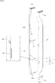
- FIG. 14 is a cross-sectional view showing a door actuating arm of an air conditioner according to an embodiment of the present invention.
- FIG. 14 show cross-sections of the portion around the door actuating arm 182 when the door unit 180 is open.
- the door actuating arm 182 is inserted and rotated in the door actuating arm support 172.
- the door actuating unit 189 is disposed at the rear end of the door actuating arm support 172.
- the door actuating unit 189 is a motor.
- a door actuating hole 182a is formed at the rear end of the door actuating arm 182 and a motor shaft of the door actuating unit 189 is directly coupled to the door actuating hole 182a.
- the rear end of the door actuating arm 182 may be rotatably connected to the door actuating arm support 172.
- FIG. 15 is a cross-sectional view showing a door rotating arm of an air conditioner according to an embodiment of the present invention.
- FIG. 15 show cross-sections of the portion around the door rotating arm 183 when the door unit 180 is open.
- the door rotating arm 183 is inserted and rotated in the door rotating arm support 173.
- a door rotating fin 183a rotatably coupled to the rear end of the door rotating arm support 173 is formed at the rear end of the door rotating arm 183.
- FIGS. 16 and 17 are exploded perspective view showing a control module of an air conditioner according to an embodiment of the present invention.
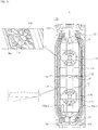
- the control module 200 includes: a control body 220 that has a remote control reception hole 221 through which a remote control signal from a remote controller passes, an output hole 222 through which output light showing an operation state passes, and an input hole 223 to which an input terminal directly receiving input from a user is connected; a control sheet 210 that is attached to the front sides of the control body 220 and is partially made of metal to prevent the remove control reception hole 221, output hole 222, and input hole 223 from being exposed to the outside; a control cover 230 that covers the rear side of the control body 220; and a control substrate 240 that is disposed inside the control body 220, receives a remote control signal passing through the remote control reception hole 221, outputs light passing through the output hole 222, and has an input terminal directly receiving input from a user.
- the control substrate 240 receives a remote control signal passing through the control sheet 210 and the remove control reception hole 221.
- the control substrate 240 emits light in seven segments implemented by an FND (Flexible Numeric Display).
- the light emitted in seven segments from the control substrate 240 passes through the output hole 222 and reaches the control sheet 210.
- the control substrate 240 shows the setting temperature of the air conditioner or the temperature of the indoor, where the air conditioner is installed, by emitting light.
- the control substrate 240 has the input terminal that receives input from a user in an electrostatic type or a pressure-sensing type. The input terminal may be fitted in the input hole 223 in contact with the control sheet 210.
- the control body 220 has the remote control reception hole 221, the output hole 222, and the input hole 223.
- a plurality of output holes 222 and input holes 223 may be formed.
- the output hole 222 is formed in seven segments corresponding to the light emitted in seven segments.
- the input terminal is inserted in the input hole 223.
- the control cover 230 protects the control substrate 240 by covering the rear side of the control body 220. That is, the control substrate 240 is disposed between the control body 220 and the control cover 230.
- the control sheet 210 prevents the remote control reception hole 221, the output hole 222, and the input hole 223 from being exposed to the outside.
- the control sheet 210 transmits a remote control signal and light.
- An input button 210c is printed at a position corresponding to the input hole 223 of the control body 220, on the front side of the control sheet 210.
- a plurality of input buttons 210c may be formed, depending on the types of buttons.
- the input button 210c may include an power button for turning on/off the air conditioner, a temperature button for controlling temperature, and a wind button for controlling the amount of air.
- a remote control reception portion 210a and an output portion 210b are printed at positions corresponding to the remote control reception hole 221 and the output hole 222 of the control body 220, on the rear side of the control sheet 210.
- the rear side of the control sheet 210 are printed with black, except for the remote control reception portion 210a and the output portion 210b, and the control reception portion 210a and the output portion 210b are printed with white.
- FIG. 18 is a view showing a control sheet of an air conditioner according to an embodiment of the present invention.
- the control sheet 210 includes: a transparent film layer 212 that is made of transparent synthetic resin; an input button printed layer 211 that is formed ahead of the transparent film layer 212, wherein the input button 210c is printed at a position of the input button printed layer 211 corresponding to the inlet hole 223 of the control body 220; a metal molding layer 213 that is disposed behind the transparent film layer 212, transmits a remote control signal and light, and is made of an opaque material; a display printed layer that is disposed behind the metal molding layer 213, wherein the output portion 210b corresponding to the output hole 222 is printed with white, and a portion except for the output portion 210b and the remote control reception portion 210a corresponding to the output hole 222 and the remote control reception hole 221 is printed with black; and a double-sided tape layer 217 that is disposed behind the display printed layer 215 and having an adhesive material to be bonded to the control body 220.
- control sheet 210 is formed by sequentially stacking the input button printed layer 211, the transparent film layer, the metal molding layer, the display printed layer 215, and the double-sided tape layer 217 from the front.
- control sheet 210 The process of manufacturing the control sheet 210 is described hereafter.
- the transparent film layer 212 made of transparent synthetic resin is prepared.
- the transparent film layer 212 may be made of PET (Polyethylene phthalate).
- UV molding is applied to the rear side of the transparent film layer 212.
- the UV molding means a process of a semi-cured/molded pattern with UV by depositing a thin coating material. After a pattern is laminated on the transparent film layer 212, the metal molding layer 213 is formed by depositing metal.
- the deposited metal may be indium.
- the output portion 210b and the remote control reception portion 210a are printed with white on the rear side of the metal molding layer 213 and the portion except for the output portion 210b and the remote control reception portion 210a is printed with black, thereby forming the display printed layer 215.
- the rear side of the display printed layer 215 may be laminated.
- the input button layer 211 is formed by printing the input button 210c on the front side of the transparent film layer 212.
- the double-sided tape layer 217 is bonded to the rear side of the display printed layer 215.
- one or more effects can be achieved as follows.
Landscapes
- Engineering & Computer Science (AREA)
- Chemical & Material Sciences (AREA)
- Combustion & Propulsion (AREA)
- Mechanical Engineering (AREA)
- General Engineering & Computer Science (AREA)
- Air Filters, Heat-Exchange Apparatuses, And Housings Of Air-Conditioning Units (AREA)
Claims (12)
- Klimaanlage, umfassend:eine rückseitige Grundtafel (110), die ein unteres rückseitiges äußeres Erscheinungsbild bildet und einen Innenraum darin aufweist;eine rückseitige Körpertafel (150), die an den oberen Abschnitt der rückseitigen Grundtafel (110) gekoppelt ist und ein oberes rückseitiges äußeres Erscheinungsbild bildet, wobei die rückseitige Körpertafel (150) einen Einlass (151a) zum Einlassen von Luft aufweist;einen Verbinder (130), der an eine Innenseite der rückseitigen Grundtafel (110) gekoppelt ist;eine vordere Grundtafel (120), die an den Verbinder (130) gekoppelt ist und ein unteres vorderes äußeres Erscheinungsbild bildet; undeine vordere Körpertafel (190), die ein oberes vorderes äußeres Erscheinungsbild bildet und einen Auslass (190a) zum Ablassen von Luft aufweist, wobei ein unteres Ende der vorderen Körpertafel (190) an die vordere Grundtafel (120) gekoppelt ist und eine Lateralseite der vorderen Körpertafel (190) an die rückseitige Körpertafel (150) gekoppelt ist;ein Gebläsemodul (140) zum Ablassen von Luft, die durch den Einlass (151a) eingelassen wurde, an den Auslass (190a);eine Abdeckungstafel (160) zum Leiten von Luft, die durch den Einlass (151a) eingelassen wurde, an das Gebläsemodul (140), wobei ein unteres Ende der Abdeckungstafel (160) an ein oberes Ende des Verbinders (130) gekoppelt ist und eine Lateralseite der Abdeckungstafel (160) an die rückseitige Körpertafel (150) gekoppelt ist; undeine Leittafel (170), die an die Abdeckungstafel (160) gekoppelt ist, um Luft vom Gebläsemodul (140) zum Auslass (190a) zu leiten,wobei das Gebläsemodul (140) zwischen der Abdeckungstafel (160) und der Leittafel (170) angeordnet ist und an die Leittafel (170) gekoppelt ist, undwobei eine untere und eine Lateralseite des Verbinders (130) zum Tragen der Abdeckungstafel (160), die mit dem Gebläsemodul (140) und der Leittafel (170) ausgestattet ist, an die rückseitige Grundtafel (110) gekoppelt sind.
- Klimaanlage nach Anspruch 1, wobei die Leittafel (170) eine Leitbohrung (170a) aufweist, durch die Luft vom Gebläsemodul (140) abgelassen wird.
- Klimaanlage nach Anspruch 2, ferner umfassend eine Türeinheit (180), die zum Schließen des Auslasses (190a) und der Leitbohrung (170a) drehbar an die Leittafel (170) gekoppelt ist.
- Klimaanlage nach einem der Ansprüche 1 bis 3, wobei das untere Ende der Abdeckungstafel (160) an das obere Ende des Verbinders (130) gekoppelt ist und die Abdeckungstafel (160) einen Abdeckungsflansch (166) aufweist, der nach unten vorsteht und an die Vorderseite des Verbinders (130) gekoppelt ist.
- Klimaanlage nach einem der Ansprüche 1 bis 4, wobei die Abdeckungstafel (160) einen Abdeckungshaken (165) aufweist, der an einer Lateralseite der Abdeckungstafel (160) vorsteht, und
die rückseitige Körpertafel (150) einen Abdeckungshaken-Kopplungsabschnitt (155) auf einer Innenseite der rückseitigen Körpertafel (150) aufweist, um den Abdeckungshaken (165) zu sichern. - Klimaanlage nach einem der Ansprüche 1 bis 5, wobei die rückseitige Grundtafel (110) einen Verbinderaufnahmeabschnitt (112) aufweist, der an einem Abschnitt der inneren Unterseite der rückseitigen Grundtafel (110) nach unten vertieft ist, um den unteren Abschnitt des Verbinders (130) aufzunehmen.
- Klimaanlage nach einem der Ansprüche 1 bis 6, wobei die rückseitige Grundtafel (110) eine Verbindersicherungsplatte (113) aufweist, die von einer Innenseite der rückseitigen Grundtafel (110) nach vorne vorsteht,
wobei der Verbinder (130) einen Sicherungsplattenaufnahmeabschnitt (131) auf einer Lateralseite des Verbinders (130) aufweist, um die Verbindersicherungsplatte (113) aufzunehmen, und ein Sicherungsplattenkopplungsabschnitt (132) am Sicherungsplattenaufnahmeabschnitt (131) gebildet ist, wobei ein vorderes Ende der Verbindersicherungsplatte (113) in den Sicherungsplattenkopplungsabschnitt (132) passt. - Klimaanlage nach einem der Ansprüche 1 bis 7, wobei die rückseitige Grundtafel (110) einen Verbindereinsetzabschnitt (114) auf einer Innenseite der rückseitigen Grundtafel (110) aufweist, wobei ein Abschnitt des Verbinders (130) in den Verbindereinsetzabschnitt (114) eingesetzt ist.
- Klimaanlage nach einem der Ansprüche 1 bis 8, wobei die vordere Grundtafel (120) einen vorderen Grundhaken (123) aufweist, der auf einer Innenseite der vorderen Grundtafel (120) vorsteht, und wobei der Verbinder (130) einen vorderen Grundhakenkopplungsabschnitt (133) aufweist, um den vorderen Grundhaken (123) zu sichern.
- Klimaanlage nach einem der Ansprüche 1 bis 9, wobei die vordere Körpertafel (190) einen vorderen Körperhaken (193) aufweist, der auf einer inneren Lateralseite der vorderen Körpertafel (190) nach unten vorsteht, und
die rückseitige Körpertafel (150) einen vorderen Körperhakenkopplungsabschnitt (157) an einer äußeren Lateralseite der rückseitigen Körpertafel (150) aufweist, wobei der vordere Körperhaken (193) von oben in den vorderen Körperhakenkopplungsabschnitt (157) eingesetzt wird. - Klimaanlage nach einem der Ansprüche 1 bis 10, wobei die vordere Körpertafel (190) einen vorderen Körperflansch (195) aufweist, der an einem unteren Ende der vorderen Körpertafel (190) vorsteht, und
die vordere Grundtafel (120) einen vorderen Körperflanschkopplungsabschnitt (125) aufweist, der auf einer oberen Innenseite der vorderen Grundtafel (120) nach hinten vorsteht, um an den vorderen Körperflansch (195) zu koppeln. - Klimaanlage nach einem der Ansprüche 1 bis 11, wobei der Verbinder (130) einen Verbinderbolzeneinsatzabschnitt (135) aufweist, in den ein Verbinderbolzen (136) zum Zusammenfügen des Verbinders (130) und der rückseitigen Grundtafel (110) eingesetzt ist.
Applications Claiming Priority (1)
| Application Number | Priority Date | Filing Date | Title |
|---|---|---|---|
| KR1020150006466A KR20160087303A (ko) | 2015-01-13 | 2015-01-13 | 공기조화기 |
Publications (3)
| Publication Number | Publication Date |
|---|---|
| EP3045834A2 EP3045834A2 (de) | 2016-07-20 |
| EP3045834A3 EP3045834A3 (de) | 2016-07-27 |
| EP3045834B1 true EP3045834B1 (de) | 2020-03-04 |
Family
ID=55129657
Family Applications (1)
| Application Number | Title | Priority Date | Filing Date |
|---|---|---|---|
| EP16151084.7A Active EP3045834B1 (de) | 2015-01-13 | 2016-01-13 | Klimaanlage |
Country Status (3)
| Country | Link |
|---|---|
| EP (1) | EP3045834B1 (de) |
| KR (1) | KR20160087303A (de) |
| CN (1) | CN105805829B (de) |
Families Citing this family (8)
| Publication number | Priority date | Publication date | Assignee | Title |
|---|---|---|---|---|
| CN108105853B (zh) * | 2017-11-27 | 2024-09-10 | 广东美的制冷设备有限公司 | 空调柜机和空调器 |
| KR102482637B1 (ko) * | 2018-01-03 | 2022-12-29 | 주식회사 위니아 | 에어컨의 측면풍 가이드 구조 |
| KR102412251B1 (ko) * | 2021-02-10 | 2022-06-22 | 엘지전자 주식회사 | 공기조화기 |
| KR20250137492A (ko) | 2024-03-11 | 2025-09-18 | 엘지전자 주식회사 | 공기조화기의 실내기 |
| KR20250137366A (ko) | 2024-03-11 | 2025-09-18 | 엘지전자 주식회사 | 공기조화기의 실내기 |
| KR20250137363A (ko) | 2024-03-11 | 2025-09-18 | 엘지전자 주식회사 | 공기조화기의 실내기 |
| KR20250137491A (ko) | 2024-03-11 | 2025-09-18 | 엘지전자 주식회사 | 공기조화기의 실내기 |
| KR20250137357A (ko) | 2024-03-11 | 2025-09-18 | 엘지전자 주식회사 | 공기조화기의 실내기 |
Family Cites Families (10)
| Publication number | Priority date | Publication date | Assignee | Title |
|---|---|---|---|---|
| TWI269013B (en) * | 2003-09-30 | 2006-12-21 | Lg Electronics Inc | Indoor unit of air conditioner |
| MXPA06005765A (es) * | 2003-10-24 | 2007-01-26 | Lg Electronics Ltd | Unidad interior en aire acondicionado. |
| KR101073501B1 (ko) * | 2004-05-18 | 2011-10-17 | 삼성전자주식회사 | 다단운전 공기조화기 |
| KR100776261B1 (ko) * | 2006-11-07 | 2007-11-15 | 삼성전자주식회사 | 공기조화기 |
| US9696046B2 (en) * | 2010-03-26 | 2017-07-04 | Trane International Inc. | Modular air handling unit |
| KR101564912B1 (ko) * | 2012-08-24 | 2015-11-16 | 삼성전자 주식회사 | 공기조화기 |
| CN104235952B (zh) * | 2013-06-14 | 2017-09-05 | Lg电子株式会社 | 空气调节器 |
| CN203671856U (zh) * | 2013-10-31 | 2014-06-25 | 广东美的制冷设备有限公司 | 上面板与背板连接结构和空调器 |
| CN203571894U (zh) * | 2013-10-31 | 2014-04-30 | 广东美的制冷设备有限公司 | 上下出风的空调器 |
| KR101385289B1 (ko) * | 2014-01-14 | 2014-04-16 | 엘지전자 주식회사 | 공기조화기 |
-
2015
- 2015-01-13 KR KR1020150006466A patent/KR20160087303A/ko not_active Ceased
-
2016
- 2016-01-13 EP EP16151084.7A patent/EP3045834B1/de active Active
- 2016-01-13 CN CN201610019533.3A patent/CN105805829B/zh active Active
Non-Patent Citations (1)
| Title |
|---|
| None * |
Also Published As
| Publication number | Publication date |
|---|---|
| CN105805829B (zh) | 2019-09-03 |
| EP3045834A3 (de) | 2016-07-27 |
| CN105805829A (zh) | 2016-07-27 |
| EP3045834A2 (de) | 2016-07-20 |
| KR20160087303A (ko) | 2016-07-21 |
Similar Documents
| Publication | Publication Date | Title |
|---|---|---|
| EP3045832B1 (de) | Klimaanlage | |
| EP3045834A2 (de) | Klimaanlage | |
| EP3187794B1 (de) | Klimaanlage | |
| US9746231B2 (en) | Indoor unit of ceiling type air-conditioner | |
| US10677475B2 (en) | Air conditioner | |
| NL2002265A (en) | Ceiling type air conditioner. | |
| US20110059686A1 (en) | Ventilator | |
| US11022325B2 (en) | Air conditioner | |
| CN205717525U (zh) | 空调室内机和空调器 | |
| EP2551607B1 (de) | Lüftungsgerät | |
| CN215909231U (zh) | 新风部件和具有其的空调器 | |
| KR101633784B1 (ko) | 공기조화기 | |
| KR20040003730A (ko) | 공기조화기 | |
| CN112303722B (zh) | 空调柜机及控制方法 | |
| CN217685437U (zh) | 壁挂式空调室内机 | |
| KR20060061847A (ko) | 공기 조화기의 실내기 | |
| KR101606045B1 (ko) | 공기조화기 | |
| CN114811738B (zh) | 空调室内机和空调器 | |
| CN215909222U (zh) | 空调器 | |
| KR102598644B1 (ko) | 천장형 공기조화기 | |
| CN101078556B (zh) | 空调器室内机的排水底盘 | |
| WO2022262304A1 (zh) | 换气装置 | |
| JP2012102889A (ja) | 床置き室内機 | |
| JP5530879B2 (ja) | 空気調和機の室内機 | |
| JP2018119713A (ja) | 天井埋込型空気調和機 |
Legal Events
| Date | Code | Title | Description |
|---|---|---|---|
| PUAI | Public reference made under article 153(3) epc to a published international application that has entered the european phase |
Free format text: ORIGINAL CODE: 0009012 |
|
| PUAL | Search report despatched |
Free format text: ORIGINAL CODE: 0009013 |
|
| AK | Designated contracting states |
Kind code of ref document: A2 Designated state(s): AL AT BE BG CH CY CZ DE DK EE ES FI FR GB GR HR HU IE IS IT LI LT LU LV MC MK MT NL NO PL PT RO RS SE SI SK SM TR |
|
| AX | Request for extension of the european patent |
Extension state: BA ME |
|
| AK | Designated contracting states |
Kind code of ref document: A3 Designated state(s): AL AT BE BG CH CY CZ DE DK EE ES FI FR GB GR HR HU IE IS IT LI LT LU LV MC MK MT NL NO PL PT RO RS SE SI SK SM TR |
|
| AX | Request for extension of the european patent |
Extension state: BA ME |
|
| RIC1 | Information provided on ipc code assigned before grant |
Ipc: F24F 13/20 20060101AFI20160620BHEP Ipc: F24F 1/00 20110101ALI20160620BHEP |
|
| STAA | Information on the status of an ep patent application or granted ep patent |
Free format text: STATUS: REQUEST FOR EXAMINATION WAS MADE |
|
| 17P | Request for examination filed |
Effective date: 20170124 |
|
| RBV | Designated contracting states (corrected) |
Designated state(s): AL AT BE BG CH CY CZ DE DK EE ES FI FR GB GR HR HU IE IS IT LI LT LU LV MC MK MT NL NO PL PT RO RS SE SI SK SM TR |
|
| REG | Reference to a national code |
Ref country code: DE Ref legal event code: R079 Ref document number: 602016030880 Country of ref document: DE Free format text: PREVIOUS MAIN CLASS: F24F0013200000 Ipc: F24F0001000700 |
|
| RIC1 | Information provided on ipc code assigned before grant |
Ipc: F24F 1/0041 20190101ALI20190808BHEP Ipc: F24F 1/0007 20190101AFI20190808BHEP Ipc: F24F 13/20 20060101ALI20190808BHEP Ipc: F24F 1/005 20190101ALI20190808BHEP |
|
| GRAP | Despatch of communication of intention to grant a patent |
Free format text: ORIGINAL CODE: EPIDOSNIGR1 |
|
| STAA | Information on the status of an ep patent application or granted ep patent |
Free format text: STATUS: GRANT OF PATENT IS INTENDED |
|
| INTG | Intention to grant announced |
Effective date: 20190916 |
|
| GRAS | Grant fee paid |
Free format text: ORIGINAL CODE: EPIDOSNIGR3 |
|
| GRAA | (expected) grant |
Free format text: ORIGINAL CODE: 0009210 |
|
| STAA | Information on the status of an ep patent application or granted ep patent |
Free format text: STATUS: THE PATENT HAS BEEN GRANTED |
|
| AK | Designated contracting states |
Kind code of ref document: B1 Designated state(s): AL AT BE BG CH CY CZ DE DK EE ES FI FR GB GR HR HU IE IS IT LI LT LU LV MC MK MT NL NO PL PT RO RS SE SI SK SM TR |
|
| REG | Reference to a national code |
Ref country code: GB Ref legal event code: FG4D |
|
| REG | Reference to a national code |
Ref country code: CH Ref legal event code: EP |
|
| REG | Reference to a national code |
Ref country code: AT Ref legal event code: REF Ref document number: 1240818 Country of ref document: AT Kind code of ref document: T Effective date: 20200315 |
|
| REG | Reference to a national code |
Ref country code: DE Ref legal event code: R096 Ref document number: 602016030880 Country of ref document: DE |
|
| REG | Reference to a national code |
Ref country code: IE Ref legal event code: FG4D |
|
| PG25 | Lapsed in a contracting state [announced via postgrant information from national office to epo] |
Ref country code: FI Free format text: LAPSE BECAUSE OF FAILURE TO SUBMIT A TRANSLATION OF THE DESCRIPTION OR TO PAY THE FEE WITHIN THE PRESCRIBED TIME-LIMIT Effective date: 20200304 Ref country code: NO Free format text: LAPSE BECAUSE OF FAILURE TO SUBMIT A TRANSLATION OF THE DESCRIPTION OR TO PAY THE FEE WITHIN THE PRESCRIBED TIME-LIMIT Effective date: 20200604 Ref country code: RS Free format text: LAPSE BECAUSE OF FAILURE TO SUBMIT A TRANSLATION OF THE DESCRIPTION OR TO PAY THE FEE WITHIN THE PRESCRIBED TIME-LIMIT Effective date: 20200304 |
|
| REG | Reference to a national code |
Ref country code: NL Ref legal event code: MP Effective date: 20200304 |
|
| PG25 | Lapsed in a contracting state [announced via postgrant information from national office to epo] |
Ref country code: GR Free format text: LAPSE BECAUSE OF FAILURE TO SUBMIT A TRANSLATION OF THE DESCRIPTION OR TO PAY THE FEE WITHIN THE PRESCRIBED TIME-LIMIT Effective date: 20200605 Ref country code: HR Free format text: LAPSE BECAUSE OF FAILURE TO SUBMIT A TRANSLATION OF THE DESCRIPTION OR TO PAY THE FEE WITHIN THE PRESCRIBED TIME-LIMIT Effective date: 20200304 Ref country code: BG Free format text: LAPSE BECAUSE OF FAILURE TO SUBMIT A TRANSLATION OF THE DESCRIPTION OR TO PAY THE FEE WITHIN THE PRESCRIBED TIME-LIMIT Effective date: 20200604 Ref country code: LV Free format text: LAPSE BECAUSE OF FAILURE TO SUBMIT A TRANSLATION OF THE DESCRIPTION OR TO PAY THE FEE WITHIN THE PRESCRIBED TIME-LIMIT Effective date: 20200304 Ref country code: SE Free format text: LAPSE BECAUSE OF FAILURE TO SUBMIT A TRANSLATION OF THE DESCRIPTION OR TO PAY THE FEE WITHIN THE PRESCRIBED TIME-LIMIT Effective date: 20200304 |
|
| REG | Reference to a national code |
Ref country code: LT Ref legal event code: MG4D |
|
| PG25 | Lapsed in a contracting state [announced via postgrant information from national office to epo] |
Ref country code: NL Free format text: LAPSE BECAUSE OF FAILURE TO SUBMIT A TRANSLATION OF THE DESCRIPTION OR TO PAY THE FEE WITHIN THE PRESCRIBED TIME-LIMIT Effective date: 20200304 |
|
| PG25 | Lapsed in a contracting state [announced via postgrant information from national office to epo] |
Ref country code: RO Free format text: LAPSE BECAUSE OF FAILURE TO SUBMIT A TRANSLATION OF THE DESCRIPTION OR TO PAY THE FEE WITHIN THE PRESCRIBED TIME-LIMIT Effective date: 20200304 Ref country code: CZ Free format text: LAPSE BECAUSE OF FAILURE TO SUBMIT A TRANSLATION OF THE DESCRIPTION OR TO PAY THE FEE WITHIN THE PRESCRIBED TIME-LIMIT Effective date: 20200304 Ref country code: ES Free format text: LAPSE BECAUSE OF FAILURE TO SUBMIT A TRANSLATION OF THE DESCRIPTION OR TO PAY THE FEE WITHIN THE PRESCRIBED TIME-LIMIT Effective date: 20200304 Ref country code: PT Free format text: LAPSE BECAUSE OF FAILURE TO SUBMIT A TRANSLATION OF THE DESCRIPTION OR TO PAY THE FEE WITHIN THE PRESCRIBED TIME-LIMIT Effective date: 20200729 Ref country code: IS Free format text: LAPSE BECAUSE OF FAILURE TO SUBMIT A TRANSLATION OF THE DESCRIPTION OR TO PAY THE FEE WITHIN THE PRESCRIBED TIME-LIMIT Effective date: 20200704 Ref country code: SK Free format text: LAPSE BECAUSE OF FAILURE TO SUBMIT A TRANSLATION OF THE DESCRIPTION OR TO PAY THE FEE WITHIN THE PRESCRIBED TIME-LIMIT Effective date: 20200304 Ref country code: SM Free format text: LAPSE BECAUSE OF FAILURE TO SUBMIT A TRANSLATION OF THE DESCRIPTION OR TO PAY THE FEE WITHIN THE PRESCRIBED TIME-LIMIT Effective date: 20200304 Ref country code: LT Free format text: LAPSE BECAUSE OF FAILURE TO SUBMIT A TRANSLATION OF THE DESCRIPTION OR TO PAY THE FEE WITHIN THE PRESCRIBED TIME-LIMIT Effective date: 20200304 Ref country code: EE Free format text: LAPSE BECAUSE OF FAILURE TO SUBMIT A TRANSLATION OF THE DESCRIPTION OR TO PAY THE FEE WITHIN THE PRESCRIBED TIME-LIMIT Effective date: 20200304 |
|
| REG | Reference to a national code |
Ref country code: AT Ref legal event code: MK05 Ref document number: 1240818 Country of ref document: AT Kind code of ref document: T Effective date: 20200304 |
|
| REG | Reference to a national code |
Ref country code: DE Ref legal event code: R097 Ref document number: 602016030880 Country of ref document: DE |
|
| PLBE | No opposition filed within time limit |
Free format text: ORIGINAL CODE: 0009261 |
|
| STAA | Information on the status of an ep patent application or granted ep patent |
Free format text: STATUS: NO OPPOSITION FILED WITHIN TIME LIMIT |
|
| PG25 | Lapsed in a contracting state [announced via postgrant information from national office to epo] |
Ref country code: AT Free format text: LAPSE BECAUSE OF FAILURE TO SUBMIT A TRANSLATION OF THE DESCRIPTION OR TO PAY THE FEE WITHIN THE PRESCRIBED TIME-LIMIT Effective date: 20200304 Ref country code: DK Free format text: LAPSE BECAUSE OF FAILURE TO SUBMIT A TRANSLATION OF THE DESCRIPTION OR TO PAY THE FEE WITHIN THE PRESCRIBED TIME-LIMIT Effective date: 20200304 Ref country code: IT Free format text: LAPSE BECAUSE OF FAILURE TO SUBMIT A TRANSLATION OF THE DESCRIPTION OR TO PAY THE FEE WITHIN THE PRESCRIBED TIME-LIMIT Effective date: 20200304 |
|
| 26N | No opposition filed |
Effective date: 20201207 |
|
| PG25 | Lapsed in a contracting state [announced via postgrant information from national office to epo] |
Ref country code: PL Free format text: LAPSE BECAUSE OF FAILURE TO SUBMIT A TRANSLATION OF THE DESCRIPTION OR TO PAY THE FEE WITHIN THE PRESCRIBED TIME-LIMIT Effective date: 20200304 Ref country code: SI Free format text: LAPSE BECAUSE OF FAILURE TO SUBMIT A TRANSLATION OF THE DESCRIPTION OR TO PAY THE FEE WITHIN THE PRESCRIBED TIME-LIMIT Effective date: 20200304 |
|
| PG25 | Lapsed in a contracting state [announced via postgrant information from national office to epo] |
Ref country code: MC Free format text: LAPSE BECAUSE OF FAILURE TO SUBMIT A TRANSLATION OF THE DESCRIPTION OR TO PAY THE FEE WITHIN THE PRESCRIBED TIME-LIMIT Effective date: 20200304 |
|
| REG | Reference to a national code |
Ref country code: CH Ref legal event code: PL |
|
| GBPC | Gb: european patent ceased through non-payment of renewal fee |
Effective date: 20210113 |
|
| PG25 | Lapsed in a contracting state [announced via postgrant information from national office to epo] |
Ref country code: LU Free format text: LAPSE BECAUSE OF NON-PAYMENT OF DUE FEES Effective date: 20210113 |
|
| REG | Reference to a national code |
Ref country code: BE Ref legal event code: MM Effective date: 20210131 |
|
| PG25 | Lapsed in a contracting state [announced via postgrant information from national office to epo] |
Ref country code: FR Free format text: LAPSE BECAUSE OF NON-PAYMENT OF DUE FEES Effective date: 20210131 |
|
| PG25 | Lapsed in a contracting state [announced via postgrant information from national office to epo] |
Ref country code: GB Free format text: LAPSE BECAUSE OF NON-PAYMENT OF DUE FEES Effective date: 20210113 Ref country code: LI Free format text: LAPSE BECAUSE OF NON-PAYMENT OF DUE FEES Effective date: 20210131 Ref country code: CH Free format text: LAPSE BECAUSE OF NON-PAYMENT OF DUE FEES Effective date: 20210131 |
|
| PG25 | Lapsed in a contracting state [announced via postgrant information from national office to epo] |
Ref country code: IE Free format text: LAPSE BECAUSE OF NON-PAYMENT OF DUE FEES Effective date: 20210113 |
|
| PGFP | Annual fee paid to national office [announced via postgrant information from national office to epo] |
Ref country code: DE Payment date: 20211206 Year of fee payment: 7 |
|
| PG25 | Lapsed in a contracting state [announced via postgrant information from national office to epo] |
Ref country code: BE Free format text: LAPSE BECAUSE OF NON-PAYMENT OF DUE FEES Effective date: 20210131 |
|
| PG25 | Lapsed in a contracting state [announced via postgrant information from national office to epo] |
Ref country code: HU Free format text: LAPSE BECAUSE OF FAILURE TO SUBMIT A TRANSLATION OF THE DESCRIPTION OR TO PAY THE FEE WITHIN THE PRESCRIBED TIME-LIMIT; INVALID AB INITIO Effective date: 20160113 |
|
| PG25 | Lapsed in a contracting state [announced via postgrant information from national office to epo] |
Ref country code: CY Free format text: LAPSE BECAUSE OF FAILURE TO SUBMIT A TRANSLATION OF THE DESCRIPTION OR TO PAY THE FEE WITHIN THE PRESCRIBED TIME-LIMIT Effective date: 20200304 |
|
| REG | Reference to a national code |
Ref country code: DE Ref legal event code: R119 Ref document number: 602016030880 Country of ref document: DE |
|
| PG25 | Lapsed in a contracting state [announced via postgrant information from national office to epo] |
Ref country code: DE Free format text: LAPSE BECAUSE OF NON-PAYMENT OF DUE FEES Effective date: 20230801 |
|
| PG25 | Lapsed in a contracting state [announced via postgrant information from national office to epo] |
Ref country code: MK Free format text: LAPSE BECAUSE OF FAILURE TO SUBMIT A TRANSLATION OF THE DESCRIPTION OR TO PAY THE FEE WITHIN THE PRESCRIBED TIME-LIMIT Effective date: 20200304 |
|
| PG25 | Lapsed in a contracting state [announced via postgrant information from national office to epo] |
Ref country code: TR Free format text: LAPSE BECAUSE OF FAILURE TO SUBMIT A TRANSLATION OF THE DESCRIPTION OR TO PAY THE FEE WITHIN THE PRESCRIBED TIME-LIMIT Effective date: 20200304 |
|
| PG25 | Lapsed in a contracting state [announced via postgrant information from national office to epo] |
Ref country code: MT Free format text: LAPSE BECAUSE OF FAILURE TO SUBMIT A TRANSLATION OF THE DESCRIPTION OR TO PAY THE FEE WITHIN THE PRESCRIBED TIME-LIMIT Effective date: 20200304 |