EP3045789B1 - Fluidsteuerungsvorrichtung - Google Patents
Fluidsteuerungsvorrichtung Download PDFInfo
- Publication number
- EP3045789B1 EP3045789B1 EP15199281.5A EP15199281A EP3045789B1 EP 3045789 B1 EP3045789 B1 EP 3045789B1 EP 15199281 A EP15199281 A EP 15199281A EP 3045789 B1 EP3045789 B1 EP 3045789B1
- Authority
- EP
- European Patent Office
- Prior art keywords
- port
- valve body
- fluid
- housing
- control device
- Prior art date
- Legal status (The legal status is an assumption and is not a legal conclusion. Google has not performed a legal analysis and makes no representation as to the accuracy of the status listed.)
- Not-in-force
Links
- 239000012530 fluid Substances 0.000 title claims description 139
- 238000007789 sealing Methods 0.000 claims description 18
- 239000000463 material Substances 0.000 claims description 7
- 230000007246 mechanism Effects 0.000 claims description 6
- 239000004033 plastic Substances 0.000 claims description 6
- 229920003023 plastic Polymers 0.000 claims description 6
- 230000009471 action Effects 0.000 claims description 3
- 238000003466 welding Methods 0.000 claims description 2
- 238000002485 combustion reaction Methods 0.000 description 16
- 239000004809 Teflon Substances 0.000 description 3
- 229920006362 Teflon® Polymers 0.000 description 3
- 230000008901 benefit Effects 0.000 description 3
- 238000004891 communication Methods 0.000 description 3
- 239000000446 fuel Substances 0.000 description 3
- 230000006698 induction Effects 0.000 description 3
- 238000004519 manufacturing process Methods 0.000 description 3
- 230000010349 pulsation Effects 0.000 description 3
- 230000001419 dependent effect Effects 0.000 description 2
- 238000005553 drilling Methods 0.000 description 2
- 239000000203 mixture Substances 0.000 description 2
- 230000002093 peripheral effect Effects 0.000 description 2
- 230000003213 activating effect Effects 0.000 description 1
- 230000008859 change Effects 0.000 description 1
- 238000010276 construction Methods 0.000 description 1
- 230000000694 effects Effects 0.000 description 1
- 230000007613 environmental effect Effects 0.000 description 1
- 230000001747 exhibiting effect Effects 0.000 description 1
- 230000002349 favourable effect Effects 0.000 description 1
- 238000002347 injection Methods 0.000 description 1
- 239000007924 injection Substances 0.000 description 1
- 230000010354 integration Effects 0.000 description 1
- 239000002991 molded plastic Substances 0.000 description 1
- 230000007704 transition Effects 0.000 description 1
Images

Classifications
-
- F—MECHANICAL ENGINEERING; LIGHTING; HEATING; WEAPONS; BLASTING
- F02—COMBUSTION ENGINES; HOT-GAS OR COMBUSTION-PRODUCT ENGINE PLANTS
- F02B—INTERNAL-COMBUSTION PISTON ENGINES; COMBUSTION ENGINES IN GENERAL
- F02B27/00—Use of kinetic or wave energy of charge in induction systems, or of combustion residues in exhaust systems, for improving quantity of charge or for increasing removal of combustion residues
- F02B27/02—Use of kinetic or wave energy of charge in induction systems, or of combustion residues in exhaust systems, for improving quantity of charge or for increasing removal of combustion residues the systems having variable, i.e. adjustable, cross-sectional areas, chambers of variable volume, or like variable means
- F02B27/0226—Use of kinetic or wave energy of charge in induction systems, or of combustion residues in exhaust systems, for improving quantity of charge or for increasing removal of combustion residues the systems having variable, i.e. adjustable, cross-sectional areas, chambers of variable volume, or like variable means characterised by the means generating the charging effect
- F02B27/0268—Valves
- F02B27/0278—Multi-way valves
-
- F—MECHANICAL ENGINEERING; LIGHTING; HEATING; WEAPONS; BLASTING
- F16—ENGINEERING ELEMENTS AND UNITS; GENERAL MEASURES FOR PRODUCING AND MAINTAINING EFFECTIVE FUNCTIONING OF MACHINES OR INSTALLATIONS; THERMAL INSULATION IN GENERAL
- F16K—VALVES; TAPS; COCKS; ACTUATING-FLOATS; DEVICES FOR VENTING OR AERATING
- F16K11/00—Multiple-way valves, e.g. mixing valves; Pipe fittings incorporating such valves
- F16K11/02—Multiple-way valves, e.g. mixing valves; Pipe fittings incorporating such valves with all movable sealing faces moving as one unit
- F16K11/08—Multiple-way valves, e.g. mixing valves; Pipe fittings incorporating such valves with all movable sealing faces moving as one unit comprising only taps or cocks
- F16K11/087—Multiple-way valves, e.g. mixing valves; Pipe fittings incorporating such valves with all movable sealing faces moving as one unit comprising only taps or cocks with spherical plug
- F16K11/0873—Multiple-way valves, e.g. mixing valves; Pipe fittings incorporating such valves with all movable sealing faces moving as one unit comprising only taps or cocks with spherical plug the plug being only rotatable around one spindle
- F16K11/0876—Multiple-way valves, e.g. mixing valves; Pipe fittings incorporating such valves with all movable sealing faces moving as one unit comprising only taps or cocks with spherical plug the plug being only rotatable around one spindle one connecting conduit having the same axis as the spindle
-
- F—MECHANICAL ENGINEERING; LIGHTING; HEATING; WEAPONS; BLASTING
- F02—COMBUSTION ENGINES; HOT-GAS OR COMBUSTION-PRODUCT ENGINE PLANTS
- F02B—INTERNAL-COMBUSTION PISTON ENGINES; COMBUSTION ENGINES IN GENERAL
- F02B37/00—Engines characterised by provision of pumps driven at least for part of the time by exhaust
- F02B37/12—Control of the pumps
- F02B37/16—Control of the pumps by bypassing charging air
- F02B37/162—Control of the pumps by bypassing charging air by bypassing, e.g. partially, intake air from pump inlet to pump outlet
-
- F—MECHANICAL ENGINEERING; LIGHTING; HEATING; WEAPONS; BLASTING
- F02—COMBUSTION ENGINES; HOT-GAS OR COMBUSTION-PRODUCT ENGINE PLANTS
- F02D—CONTROLLING COMBUSTION ENGINES
- F02D9/00—Controlling engines by throttling air or fuel-and-air induction conduits or exhaust conduits
- F02D9/08—Throttle valves specially adapted therefor; Arrangements of such valves in conduits
- F02D9/10—Throttle valves specially adapted therefor; Arrangements of such valves in conduits having pivotally-mounted flaps
- F02D9/1005—Details of the flap
- F02D9/101—Special flap shapes, ribs, bores or the like
-
- F—MECHANICAL ENGINEERING; LIGHTING; HEATING; WEAPONS; BLASTING
- F02—COMBUSTION ENGINES; HOT-GAS OR COMBUSTION-PRODUCT ENGINE PLANTS
- F02D—CONTROLLING COMBUSTION ENGINES
- F02D9/00—Controlling engines by throttling air or fuel-and-air induction conduits or exhaust conduits
- F02D9/08—Throttle valves specially adapted therefor; Arrangements of such valves in conduits
- F02D9/10—Throttle valves specially adapted therefor; Arrangements of such valves in conduits having pivotally-mounted flaps
- F02D9/1005—Details of the flap
- F02D9/1025—Details of the flap the rotation axis of the flap being off-set from the flap center axis
- F02D9/103—Details of the flap the rotation axis of the flap being off-set from the flap center axis the rotation axis being located at an edge
-
- F—MECHANICAL ENGINEERING; LIGHTING; HEATING; WEAPONS; BLASTING
- F02—COMBUSTION ENGINES; HOT-GAS OR COMBUSTION-PRODUCT ENGINE PLANTS
- F02D—CONTROLLING COMBUSTION ENGINES
- F02D9/00—Controlling engines by throttling air or fuel-and-air induction conduits or exhaust conduits
- F02D9/08—Throttle valves specially adapted therefor; Arrangements of such valves in conduits
- F02D9/10—Throttle valves specially adapted therefor; Arrangements of such valves in conduits having pivotally-mounted flaps
- F02D9/1035—Details of the valve housing
- F02D9/104—Shaping of the flow path in the vicinity of the flap, e.g. having inserts in the housing
-
- F—MECHANICAL ENGINEERING; LIGHTING; HEATING; WEAPONS; BLASTING
- F02—COMBUSTION ENGINES; HOT-GAS OR COMBUSTION-PRODUCT ENGINE PLANTS
- F02D—CONTROLLING COMBUSTION ENGINES
- F02D9/00—Controlling engines by throttling air or fuel-and-air induction conduits or exhaust conduits
- F02D9/08—Throttle valves specially adapted therefor; Arrangements of such valves in conduits
- F02D9/10—Throttle valves specially adapted therefor; Arrangements of such valves in conduits having pivotally-mounted flaps
- F02D9/109—Throttle valves specially adapted therefor; Arrangements of such valves in conduits having pivotally-mounted flaps having two or more flaps
- F02D9/1095—Rotating on a common axis, e.g. having a common shaft
-
- F—MECHANICAL ENGINEERING; LIGHTING; HEATING; WEAPONS; BLASTING
- F02—COMBUSTION ENGINES; HOT-GAS OR COMBUSTION-PRODUCT ENGINE PLANTS
- F02M—SUPPLYING COMBUSTION ENGINES IN GENERAL WITH COMBUSTIBLE MIXTURES OR CONSTITUENTS THEREOF
- F02M35/00—Combustion-air cleaners, air intakes, intake silencers, or induction systems specially adapted for, or arranged on, internal-combustion engines
- F02M35/10—Air intakes; Induction systems
- F02M35/10006—Air intakes; Induction systems characterised by the position of elements of the air intake system in direction of the air intake flow, i.e. between ambient air inlet and supply to the combustion chamber
- F02M35/10026—Plenum chambers
- F02M35/10065—Valves arranged in the plenum chamber
-
- F—MECHANICAL ENGINEERING; LIGHTING; HEATING; WEAPONS; BLASTING
- F02—COMBUSTION ENGINES; HOT-GAS OR COMBUSTION-PRODUCT ENGINE PLANTS
- F02M—SUPPLYING COMBUSTION ENGINES IN GENERAL WITH COMBUSTIBLE MIXTURES OR CONSTITUENTS THEREOF
- F02M35/00—Combustion-air cleaners, air intakes, intake silencers, or induction systems specially adapted for, or arranged on, internal-combustion engines
- F02M35/10—Air intakes; Induction systems
- F02M35/10242—Devices or means connected to or integrated into air intakes; Air intakes combined with other engine or vehicle parts
- F02M35/10255—Arrangements of valves; Multi-way valves
-
- Y—GENERAL TAGGING OF NEW TECHNOLOGICAL DEVELOPMENTS; GENERAL TAGGING OF CROSS-SECTIONAL TECHNOLOGIES SPANNING OVER SEVERAL SECTIONS OF THE IPC; TECHNICAL SUBJECTS COVERED BY FORMER USPC CROSS-REFERENCE ART COLLECTIONS [XRACs] AND DIGESTS
- Y02—TECHNOLOGIES OR APPLICATIONS FOR MITIGATION OR ADAPTATION AGAINST CLIMATE CHANGE
- Y02T—CLIMATE CHANGE MITIGATION TECHNOLOGIES RELATED TO TRANSPORTATION
- Y02T10/00—Road transport of goods or passengers
- Y02T10/10—Internal combustion engine [ICE] based vehicles
- Y02T10/12—Improving ICE efficiencies
Definitions
- the invention relates to a fluid control device, in particular to an air intake shifter for air ducts of internal combustion engines of vehicles, more particularly, it relates to a charge air duct for a turbocharged engine, such as a one-stage turbocharged engine.
- Charge air within the meaning of the invention shall be understood as compressed air, compressed by an exhaust turbocharger or any other kind of charger or compressor.
- charge air ducts also called charge air delivery ducts
- geometry is tuned to take benefits from pressure waves for improving the air filling into the engine cylinders and thus increase the output torque.
- charge air ducts are dependent on engine speed. At high engine speeds, for instance above around 1500 rpm (revolutions per minute), and high load, the turbocharger compresses the supplied air in an effective manner. Under these engine operating conditions, a charge air duct of small length and larger diameter is suitable in order to reduce pressure loss and increase the engine power.
- the turbocharger compressor At low engine speeds (around 1250 rpm for instance) and part load operation, the turbocharger compressor is not very effective (the charging effect of the turbocharger is poor and limits the engine output torque). Under these engine operating conditions, a longer duct having a reduced inlet diameter is appropriate in order to increase the engine feeding (i.e. the mass of gas introduced into the combustion chamber) and thus the volumetric efficiency.
- DE10314629A1 discloses an induction system for an internal combustion engine which has a rotary valve directing the incoming fuel/air mixture either through a short wide induction pipe or a narrow long induction pipe.
- the fuel/air mixture passes through an inlet channel into a chamber with several short wide tubes and long narrow tubes leading to the individual cylinders.
- a rotary valve body forms part of a valve assembly and is accommodated in a cylindrical housing.
- the housing has a wide opening for each cylinder and a narrow opening. The valve body is rotated to line up wide or narrow passages with the entry port for each cylinder.
- the WO 97/05413 A1 displays an arrangement of a distributing valve for fluids, and comprising a housing and internally in the housing a rotatable hemispherical fluid distributing element, where the housing comprises a number of inlets each from its source of fluid and one main outlet for a common flow of fluid which is led out of the housing.
- DE 90 02 393 U1 displays a plug valve which is radially centered on the axis of rotation and is fixed between a lower housing portion and a valve body.
- the axial-groove ball bearing which is centered on the axis of rotation, is fixed between the upper housing-part and the flat front face of the plug.
- a switch valve (10) is known provided with an upper body having a plurality of outlet ports and lower body housing with inlet port.
- the switch valve includes a ball member which is rotatable within the switch valve body for selective fluid communication between the inlet port and the selected one of the plurality of outlet ports.
- WO 98/37342 A2 presents a changeover valve which accommodates thermal transients which is operable over a range of temperatures includes a crossover member and a seat assembly in each outlet passage, a thrust bearing rotatably supporting the crossover member and a split load ring comprising an inner ring and an outer ring threaded into the changeover valve body.
- a rotation-symmetrical plug which is located in the housing rotatable around its axis and which can be turned by means of a switch mechanism into different positions.
- the main connection and one end of the arc-shaped passage are arranged coaxially to the rotary axis and the arc-shaped center line of the passage lies in a plane running through the rotary axis.
- WO 99/170008 A1 shows charge air systems including a small electric motor-driven compressor for supplying charge air to four-cycle internal combustion engines, including systems with turbocharger charge air compressors in series and parallel connection.
- US 2 996 083 A shows a valve for communicating a plurality of lines with a main line and for selectively by-passing flow through any one of said plurality of lines to a secondary line, and including, a substantially elongate body having upper and lower sections and with a peripheral wall to define a chamber therein, a plurality of flow lines opening into ports in the wall of the body and to be in communication with the chamber at the upper section of the body.
- a valve for communicating a plurality of lines with a main line and for selectively by-passing flow through any one of said plurality of lines to a secondary line, and including, a substantially elongate body having upper and lower sections and with a peripheral wall to define a chamber therein, a plurality of flow lines opening into ports in the wall of the body and to be in communication with the chamber at the upper section of the body.
- a fluid control device comprising a housing with one first port and with at least one second port, wherein a control means is arranged within the housing to control a fluid flow between the first port and the at least one second port.
- a fluid control device in particular an air intake shifter, which comprises a housing with one first port having a first main axis and with at least one second port having at least one second main axis.
- the first main axis is perpendicular to the cross section of the first port and the one second main axis is perpendicular to the cross section of the at least one second port.
- the first main axis and the at least one second main axis are aligned off-axis to one another.
- a control means is arranged within the housing to control a fluid flow between the first port and the at least one second port.
- the control means comprises a valve body being rotatable around the first main axis of the first port, whereas the valve body comprises a fluid path for guiding the fluid through the valve body.
- the control means are enabling the fluid flow between the first port and the second port by connecting the first and the second port via the fluid path or between the first port and a third port by connecting the first and the third port via the fluid path.
- the flow direction of the fluid can be from the second port or third port to the first port or alternatively from the first port to the second or the third port.
- the proposed inventive fluid control device deals with a product which is able to shift a fluid flow path from one first port to at least a second port while keeping the pressure losses of the fluid during passage through the fluid control device low.
- the inventive fluid control device on the contrary is able to withstand high fluid pressures and high levels of fluid pulsation without significant losses of fluid pressure. Further, the fluid control device is characterized by a high level of fluid tightness at the end positions of a valve body of the control means.
- the inventive fluid control device may be used as an air intake shifter for air ducts of internal combustion engines of vehicles if the ports of the fluid control device are connected to two inlets and one outlet of the air duct, for instance. Thus it may be part of an active charge air duct.
- the fluid control device may be used as a shutter, if the ports of the fluid control device are connected to one inlet and one outlet of the air duct.
- the valve body of the control means of the inventive fluid control device is able to rotate around the first main axis of the first port, thus an axle of the valve body does not cause any significant pressure drop of the fluid flow as it is directed in the fluid flow direction.
- the fluid path which may be manufactured by drilling the valve body in order to provide a unique fluid path inside the valve body, is always connected and open to the first port, whereas the other side of the fluid path is either connected and open to a second port or by rotating the valve body to a third port.
- the fluid path may be partly open to both second and third ports, thus providing a partly open connection from the second and the third port to the first port and mixing the fluid flows from both second and third port when feeding to the first port.
- the fluid control device does not exhibit a third port, it can be used to open or close the second port in order to work as a shutter for the second port.
- the valve body has at least one outer surface section having a spherical shape. If the valve body is constructed as a sphere or at least part of the valve body is realized as a part of a sphere, where the valve body may be of generally spherical shape, but with edges and recesses, it is quite convenient and efficient to rotate it around the main axis of the first port. The moment of inertia can thus be kept quite low thus enabling to rotate the valve body at a high speed and with a low activating torque.
- At least a section of an inner surface of the housing has a spherical shape corresponding to the outer surface section of the valve body.
- a seal groove for a gasket is formed in the valve body to receive the gaskets. It extends along the surface into the valve body. With an integration of the groove in the valve body the tolerances between valve body with gasket and the valve housing can be kept small.
- the package needed for the sealing area is optimized by forming the groove within the valve body.
- the sealing area on side of the housing can be shaped in a flat manner.
- the manufacturing of the housing as an injection molded plastic part is easy and possible without any complex tool. Forming a groove for a gasket in a convex curved valve body is less complex than a forming a groove on a concave curved inner surface of a housing.
- the inner surface of the housing does not have any gasket groove shaped features in the sealing area.
- the housing comprises at least a first shell and a second shell.
- This enables convenient assembly conditions, because thus the valve body may be inserted into one of the shells, then the other shell may be put on top of the valve body and the first shell and finally both shells are closed and tightened by welding.
- This also exhibits a very modular construction of the fluid control device, because by changing one of the two shells, where the first shell, for instance, carries the first port and the second shell carries the second and the third port, an alternative type of fluid control device may be assembled, exhibiting different ports concerning mechanical interfaces or a different number of ports or changing the fluid control device from an air intake shifter to a shutter or vice versa.
- a fluid connection may be established between the first port and the at least one second port and in a second position of a valve body of the control means the fluid connection between the first port and the at least one second port may be closed.
- a switching or shifting or alternatively a shutter behavior of the fluid control device may be realized where the fluid path is open from the first port to the second port in one position, whereas the fluid path from the first port to the second port is closed in a second position. If the housing carries a third port, in the second position the fluid path may be open from the first port to the third port. If the housing does not carry a third port then the fluid control device is working as a shutter and closes the fluid path simply in the second position.
- valve body may be arranged to provide a fluid connection alternatively between the first port and the second port or between the first port and at least a third port.
- the second and third ports may be at least partially open to the first port.
- a mixing function between two input flows from the second and the third port guided to the first port may be realized for optimizing a certain combustion function of an engine, for instance.
- the valve body is two-dimensionally sealed by gaskets to the first port and the at least one second port.
- the fluid tightness is ensured by a sealing area at the interface between an opening of the fluid path in the valve body and the first or second port provided in the housing of the fluid control device.
- the sealing area is two-dimensional to ensure the reliability of the sealing function. This is achieved by a gasket around the two-dimensional plane of the opening of the fluid path in the valve body in cylinder shape, sealed to the spherical inner surface of the housing around the first or second port. A groove for a gasket around a two-dimensional plane formed by the valve body results in a tight sealing.
- valve body may be rotatable by action of a driving mechanism located outside the housing.
- a rotating axle of the valve body may be fed through the housing in order to be coupled to an actuator as a driving mechanism of the control means of the fluid control device.
- an actuator can be a vacuum actuator, e.g., which is a very common type of actuator in combination with combustion engines, particularly in vehicles.
- an electric actuator can be used for rotating the valve body.
- the housing and the valve body are made of plastics materials.
- Plastics materials are not only very convenient for manufacturing different shapes of devices, but are also a cheap and flexible way of producing in a high output.
- a Teflon segment for the sealing area of the valve body and as a counterpart other plastics materials for the correspondding inner surface of the housing.
- a segment for the sealing can consist of a suitable material different to Teflon as well.
- an air intake shifter comprising a fluid control device, having a first port, a second port and a third port, wherein the first port is alternatively coupleable to the second port or the third port by a control means, which is rotatable about a main axis of the first port, which main axis is perpendicular to the cross section of the first port.
- a switching or shifting behavior of the fluid control device may be realized where the fluid path is open from the first port to the second port in one position, whereas the fluid path from the first port to the second port is closed in a second position. If the housing carries a third port, in the second position the fluid path may be open from the first port to the third port.
- the first port may be an air outlet and the second port may be an air inlet for charge air and the third port may be an air inlet for pulsating air.
- the charge air may be generated by a turbocharger, whereas the pulsating air may be generated by a resonance device.
- Different load conditions of combustion engines may be optimized by an optimized supply of air for the combustion process.
- the fluid control device can thus be used for a shifting of the air inlet according to the load conditions of the combustion engine. Shifting may be achieved dependent on specific engine speeds and engine load, or other engine parameters like temperature, pressure, mass flow or others.
- a fluid shutter according to claim 8 comprising a fluid control device, having a first port and a second port, wherein a fluid connection between the first port and the second port is switchable by a control means, which is rotatable about a main axis of the first port, which main axis is perpendicular to the cross section of the first port.
- a shutter behavior of the fluid control device may be realized where the fluid path is open from the first port to the second port in one position of a valve body, whereas the fluid path from the first port to the second port is closed in a second position. If the housing does not carry a third port then the fluid control device is working as a shutter and closes the fluid path simply in the second position of the valve body.
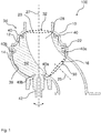
- Figure 1 depicts in a cross cut view a first example embodiment of a fluid control device 100 according to the invention in a first position of a valve body 24 of a control means 22, where a fluid path 28 is open from a first port 20 to a second port 16.
- the fluid control device 100 in Figure 1 for instance an air intake shifter, is comprising a housing 10 with one first port 20 having a first main axis 27 perpendicular to the cross section of the first port 20 and with one second port 16 having one second main axis 25 perpendicular to the cross section of the second port 16.
- the fluid control device 100 also has a third port 18, which cannot be seen in Figure1 , but is depicted in Figure 2 .
- the first main axis 27 and the second main axis 25 are aligned off-axis to one another.
- the control means 22 is arranged within the housing 10 to control a fluid flow between the first port 20 and the second port 16, as well as the third port 18.
- the control means 22 comprises a valve body 24 being rotatable around the first main axis 27 of the first port 20 for changing the position of a valve body 24 of the control means 22.
- the valve body 24 comprises a fluid path 28 for guiding the fluid through the valve body 24.
- the fluid path 28 may be manufactured by drilling the valve body 24.
- the valve body 24 has an outer surface section having at least partly a spherical shape, whereas at least a section of the inner surface 38 of the housing 10 has a spherical shape corresponding to the outer surface section of the valve body 24. Accordingly, rotating of the valve body 24 within the housing 10 around the main axis 27 can easily be achieved, and the surface 38 of the housing 10 serves as a bearing for the valve body 24.
- the housing 10 comprises a first shell 12 and a second shell 14.
- the valve body 24 is mainly carried by the second shell 14.
- the second shell 14 incorporates the second port 16 and the third port 18 (shown in Figure 2 ), whereas the first port 20 is located in the first shell 12.
- the first shell 12 closes the second shell 14 to get a sealed housing 10.
- valve body 24 of the control means 22 In the first position 34 of the valve body 24 of the control means 22, shown in Figure 1 , a fluid connection is established between the first port 20 and the second port 16, thus enabling fluid flow from the second port 16 to the first port 20 via fluid path 28 and vice versa.
- the valve body 24 is arranged to provide a fluid connection alternatively between the first port 20 and the second port 16 and the second port 16 or between the first port 20 and at least a third port 18.
- the valve body 24 is two-dimensionally sealed to the first port 20 by gaskets 40 and to the second port 16 by gaskets 40a.
- the fluid tightness may be ensured by a sealing area at the interface between the opening 32 of the fluid path 28 in the valve body 24 and the first port 20 provided in the housing 10 of the fluid control device 100.
- the sealing area may be kept two-dimensional to ensure the reliability of the sealing function. This can be achieved by a gasket 40 around the two-dimensional plane of the opening 32 of the fluid path 28 in the valve body 24 in cylinder shape, sealed to the spherical inner surface 38 of the housing 10 around the first port 20.
- valve body 24 is sealed to the inner surface 38 of the housing 10 with the gasket 40a around the opening 30 of the fluid path 28 and with the gasket 40b around the closed area of the valve body 24, if the valve body 24 is in the second position 36, where the fluid path 28 is open from the first port 20 to the third port 18 and closed from the first port 20 to the second port 16.
- the second port 16 is sealed by the valve body 24 via the gasket 40b.
- the seal grooves for the gaskets 40, 40a, 40b are formed in the valve body 24 to receive the gaskets.
- the inner surface 38 of the housing 10 does not have any gasket groove shaped features in the sealing area.
- the valve body 24 is rotatable by action of a driving mechanism located outside the housing 10.
- a rotating axle 42 of the valve body 24 is fed through the housing 10 in order to be coupled to an actuator as a driving mechanism of the control means 22 of the fluid control device 100.
- an actuator can be a vacuum actuator, e.g., which is a very common type of actuator in combination with combustion engines, particularly in vehicles.
- an electric actuator can be used for rotating the valve body 24.
- the housing 10 and/or the valve body 24 can favorably be made of plastics materials. It is advantageous to use, for instance, a Teflon segment for the sealing area of the valve body 24 and as a counterpart other plastics materials for the corresponding inner surface 38 of the housing 10. Thus, a very efficient and reliable sealing function is achievable in an economic way.
- Figure 2 depicts in a cross cut view the example embodiment of the fluid control device 100 according to Figure 1 in a second position 36 where the fluid path 28 is open from the first port 20 to a third port 18.
- the valve body 24 is rotated around the main axis 27 such that the fluid path 28 connects the first port 20 and the third port 18 and the fluid flow between the third port 18 and the first port 20 is enabled.
- the opening 30 of the fluid path 28 is connected to the third port 18, whose main axis 26 is aligned off-axis to the main axis 27 of the first port 20.
- the second port 16 is closed by the valve body 24.
- the second and third ports 16, 18 may be at least partially open to the first port 20, resulting in a mixing of the fluid flow from different branches of the fluid duct via the second and the third port 16, 18.
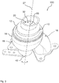
- FIG 3 an isometric view of the example embodiment of the fluid control device 100 according to Figure 1 with a first port 20, a second port 16, and a third port 18 is shown.
- the housing 10 comprises a first shell 12 and a second shell 14 assembled and sealed together.
- the second shell 14 carries the second port 16 and in an axially distant position the third port 18.
- the first shell 12 carries the first port 20 on top of the housing 10.
- the first port 20 is always connected to the opening 32 of the valve body 24 to the fluid path 28, as the valve body 24 is rotatable around the main axis 27 of the first port 20.
- the fluid control device 100 may represent an air intake shifter, which comprises the fluid control device 100, having a first port 20, a second port 16 and a third port 18, wherein the first port 20 is alternatively coupleable to the second port 16 or the third port 18 by a control means 22, which is rotatable about a main axis 27 of the first port 20, which main axis 27 is perpendicular to the cross section of the first port 20.
- the first port 20 is an air outlet and the second port 16 is an air inlet for charge air and the third port 18 is an air inlet for pulsating air.
- the charge air may be generated by a turbocharger, whereas the pulsating air may be generated by a resonance device.
- the fluid control device 100 may represent a fluid shutter comprising a fluid control device 100, having a first port 20 and a second port 16, wherein a fluid connection between the first port 20 and the second port 16 is switchable by a control means 22, which is rotatable about a main axis 27 of the first port 20, which main axis 27 is perpendicular to the cross section of the first port 20.
- a shutter behavior of the fluid control device 100 may be realized where the fluid path 28 is open from the first port 20 to the second port 16 in one position 34 of the valve body 24, whereas the fluid path 28 from the first port 20 to the second port 16 is closed in a second position 36 of the valve body 24.
Landscapes
- Engineering & Computer Science (AREA)
- General Engineering & Computer Science (AREA)
- Mechanical Engineering (AREA)
- Chemical & Material Sciences (AREA)
- Combustion & Propulsion (AREA)
- Multiple-Way Valves (AREA)
Claims (8)
- Fluidsteuereinrichtung (100), insbesondere ein Lufteinlassschieber, umfassend ein Gehäuse (10) mit einem ersten Kanal (20) mit einer ersten Hauptachse (27) und mit mindestens einem zweiten Kanal (16, 18) mit mindestens einer zweiten Hauptachse (25, 26), wobeiI. die erste Hauptachse (27) und die mindestens zweite Hauptachse (25, 26) achsversetzt zueinander ausgerichtet sind,II. ein Steuermittel (22) in dem Gehäuse (10) angeordnet ist, um die Fluidströmung zwischen dem ersten Kanal (20) und dem mindestens zweiten Kanal (16, 18) zu regeln,III. das Steuermittel (22) einen Ventilkörper (24) umfasst, welcher sich um die erste Hauptachse (27) des ersten Kanals (20) drehen kann, wobei der Ventilkörper (24) einen Fluidpfad (28) zum Leiten des Fluids durch den Ventilkörper (24) umfasst,
wobei der Ventilkörper (24) mindestens einen äußeren Oberflächenabschnitt mit einer kugelförmigen Form hat, wobei mindestens ein Abschnitt einer inneren Oberfläche (38) des Gehäuses (10) eine kugelförmige Form hat, welche dem äußeren Oberflächenabschnitt des Ventilkörpers (24) entspricht, wobei das Gehäuse (10) mindestens eine erste Schale (12) und einer zweite Schale (14) aufweist, wobei die erste Schale und letztendlich beide Schalen mittels Verschweißen geschlossen und festgezogen werden, wobei der Ventilkörper (24) zweidimensional mittels Dichtungen (40) zu dem ersten Kanal (20) und dem mindestens einen zweiten Kanal (16, 18) abgedichtet ist, wobei das Gehäuse (10) und der Ventilkörper (24) aus Kunststoffmaterial hergestellt sind, wobei der Abdichtbereich zweidimensional ist, wobei die Dichtung (40) um die zweidimensionale Ebene der Öffnung des Fluidpfads in dem Ventilkörper (24) zylinderförmig ist und zu der kugelförmigen inneren Oberfläche (38) des Gehäuses (10) um den ersten Kanal (20) oder zweiten Kanal (16, 18) abgedichtet ist, wobei eine Nut für eine Dichtung (40) um eine zweidimensionale Ebene durch den Ventilkörper (24) gebildet ist. - Fluidsteuereinrichtung nach Anspruch 1, wobei in einer ersten Position (34) eines Ventilkörpers (24) des Steuermittels (22) ein Fluidanschluss zwischen dem ersten Kanal (20) und dem mindestens einen zweiten Kanal (16, 18) hergestellt ist und in einer zweiten Position (36) des Ventilkörpers (24) des Steuermittels (22) der Fluidanschluss zwischen dem ersten Kanal (20) und dem mindestens einen zweiten Kanal (16, 18) geschlossen ist.
- Fluidsteuereinrichtung nach einem der obigen Ansprüche, wobei der Ventilkörper (24) so angeordnet ist, um einen Fluidanschluss abwechselnd zwischen dem ersten Kanal (20) und dem zweiten Kanal (16) oder zwischen dem ersten Kanal (20) und mindestens einem dritten Kanal (18) vorzusehen.
- Fluidsteuereinrichtung nach Anspruch 3, wobei in mindestens einer Position eines Ventilkörpers (24) des Steuermittels (22) der zweite und dritte Kanal (16, 18) mindestens teilweise zum ersten Kanal (20) geöffnet sind.
- Fluidsteuereinrichtung nach einem der obigen Ansprüche, wobei der Ventilkörper (24) durch einen außerhalb des Gehäuses (10) angeordneten Antriebsmechanismus drehbar ist.
- Lufteinlassschieber umfassend eine Fluidsteuereinrichtung (100) nach einem der obigen Ansprüche, mit einem ersten Kanal (20), einem zweiten Kanal (16) und einem dritten Kanal (18), wobei der erste Kanal (20) abwechselnd mit dem zweiten Kanal (16) oder dem dritten Kanal (18) durch das Steuermittel (22) koppelbar ist, welches um die Hauptachse (27) des ersten Kanals (20) drehbar ist, welche Hauptachse (27) senkrecht zum Querschnitt des ersten Kanals (20) ist.
- Lufteinlassschieber nach Anspruch 6, wobei der erste Kanal (20) ein Luftauslass und der zweite Kanal (16) ein Lufteinlass für Ladeluft und der dritte Kanal (18) ein Lufteinlass für pulsierende Luft ist.
- Fluidverschluss umfassend eine Fluidsteuereinrichtung (100) nach einem der Ansprüche 1 bis 5, mit einem ersten Kanal (20) und einem zweiten Kanal (16), wobei ein Fluidanschluss zwischen dem ersten Kanal (20) und dem zweiten Kanal (16) durch das Steuermittel (22) schaltbar ist, welches um die Hauptachse (27) des ersten Kanals (20) drehbar ist, welche Hauptachse (27) senkrecht zum Querschnitt des ersten Kanals (20) ist.
Priority Applications (1)
| Application Number | Priority Date | Filing Date | Title |
|---|---|---|---|
| EP15199281.5A EP3045789B1 (de) | 2015-01-15 | 2015-12-10 | Fluidsteuerungsvorrichtung |
Applications Claiming Priority (2)
| Application Number | Priority Date | Filing Date | Title |
|---|---|---|---|
| EP15290007.2A EP3045790A1 (de) | 2015-01-15 | 2015-01-15 | Fluidsteuerungsvorrichtung |
| EP15199281.5A EP3045789B1 (de) | 2015-01-15 | 2015-12-10 | Fluidsteuerungsvorrichtung |
Publications (2)
| Publication Number | Publication Date |
|---|---|
| EP3045789A1 EP3045789A1 (de) | 2016-07-20 |
| EP3045789B1 true EP3045789B1 (de) | 2017-09-20 |
Family
ID=52395015
Family Applications (2)
| Application Number | Title | Priority Date | Filing Date |
|---|---|---|---|
| EP15290007.2A Withdrawn EP3045790A1 (de) | 2015-01-15 | 2015-01-15 | Fluidsteuerungsvorrichtung |
| EP15199281.5A Not-in-force EP3045789B1 (de) | 2015-01-15 | 2015-12-10 | Fluidsteuerungsvorrichtung |
Family Applications Before (1)
| Application Number | Title | Priority Date | Filing Date |
|---|---|---|---|
| EP15290007.2A Withdrawn EP3045790A1 (de) | 2015-01-15 | 2015-01-15 | Fluidsteuerungsvorrichtung |
Country Status (3)
| Country | Link |
|---|---|
| US (1) | US20160208938A1 (de) |
| EP (2) | EP3045790A1 (de) |
| CN (1) | CN105804859A (de) |
Families Citing this family (1)
| Publication number | Priority date | Publication date | Assignee | Title |
|---|---|---|---|---|
| DE102019112559A1 (de) * | 2019-05-14 | 2020-11-19 | Vat Holding Ag | Wegeventil mit einem Ventilgehäuse |
Family Cites Families (25)
| Publication number | Priority date | Publication date | Assignee | Title |
|---|---|---|---|---|
| US713466A (en) * | 1902-01-18 | 1902-11-11 | Frank J Louis | Cut-off for drain-pipes. |
| US2558260A (en) * | 1944-09-05 | 1951-06-26 | Parker Appliance Co | Valve assembly |
| US2996083A (en) * | 1958-07-10 | 1961-08-15 | Huska Paul | Continuous flow rotary selector valve |
| US3100499A (en) * | 1961-07-21 | 1963-08-13 | Gen Dynamics Corp | Valve |
| US3345032A (en) * | 1964-11-10 | 1967-10-03 | Jamesbury Corp | Three-way ball valve |
| US3735956A (en) * | 1972-04-10 | 1973-05-29 | Whitey Research Tool Co | Ball valve and improved seat arrangement |
| US4043359A (en) * | 1976-05-05 | 1977-08-23 | Masco Corporation Of Indiana | Water faucet |
| US4173234A (en) * | 1977-11-25 | 1979-11-06 | Waterous Company | Transfer valve |
| GB2221954B (en) * | 1988-08-16 | 1992-07-08 | Austin Rover Group | An internal combustion engine inlet manifold |
| DE9002393U1 (de) * | 1990-03-01 | 1990-05-03 | Wäscher, Thomas, Dipl.-Ing., 6900 Heidelberg | Mehrwegehahn mit elektrischem Antrieb |
| DE4210659C2 (de) * | 1992-03-31 | 1995-06-29 | Abk Armaturenbau Gmbh | Mehrwegearmatur mit molchbarem Durchgang |
| IT1261603B (it) * | 1993-10-08 | 1996-05-23 | Gevipi Ag | Dispositivo di tenuta con guarnizione di sezione quadrata, per rubinetto miscelatore ad atturatore sferico. |
| US5549138A (en) * | 1995-01-10 | 1996-08-27 | Crosby Valve & Gage Company | Changeover valve system |
| US5727595A (en) * | 1995-01-10 | 1998-03-17 | Eminger; Harry E. | Changeover valve system having a cross drive member |
| NO952991D0 (no) * | 1995-07-28 | 1995-07-28 | Siegmund Nafz | Anordning ved ventil |
| US6029452A (en) * | 1995-11-15 | 2000-02-29 | Turbodyne Systems, Inc. | Charge air systems for four-cycle internal combustion engines |
| US5727596A (en) * | 1997-02-25 | 1998-03-17 | Fmc Corporation | Changeover valve |
| US6240946B1 (en) * | 1998-09-17 | 2001-06-05 | Tyco Flow Control, Inc. | Switch valve |
| DE10235997A1 (de) * | 2002-08-06 | 2004-02-19 | Otto Altmann | Medienmassen-Steuerelement und Ansaugvorrichtung für Verbrennungsmotoren |
| DE10314629B4 (de) | 2003-04-01 | 2014-04-03 | Mahle Filtersysteme Gmbh | Sauganlage für eine Brennkraftmaschine |
| DE102004012507A1 (de) * | 2004-03-15 | 2005-10-06 | Siemens Ag | Drosselklappenstutzen |
| CN201034178Y (zh) * | 2006-12-11 | 2008-03-12 | 克拉玛依市金牛信泰工业控制有限公司 | 扇形流道密封副多通阀 |
| DE102007017828A1 (de) * | 2007-04-16 | 2008-10-23 | Siemens Ag | Turbolader, turboaufgeladene Brennkraftmaschine, Verfahren und Verwendung |
| JP2013124847A (ja) * | 2011-12-16 | 2013-06-24 | Calsonic Kansei Corp | 流路切替弁、及びその流路切替弁を備えた車両用空気調和装置 |
| DE202013008996U1 (de) * | 2013-10-10 | 2013-11-06 | Borgwarner Inc. | Verdichterbypassventil für ein mehrstufiges Aufladesystem |
-
2015
- 2015-01-15 EP EP15290007.2A patent/EP3045790A1/de not_active Withdrawn
- 2015-12-10 EP EP15199281.5A patent/EP3045789B1/de not_active Not-in-force
-
2016
- 2016-01-13 US US14/994,319 patent/US20160208938A1/en not_active Abandoned
- 2016-01-15 CN CN201610025874.1A patent/CN105804859A/zh active Pending
Non-Patent Citations (1)
| Title |
|---|
| None * |
Also Published As
| Publication number | Publication date |
|---|---|
| US20160208938A1 (en) | 2016-07-21 |
| EP3045789A1 (de) | 2016-07-20 |
| EP3045790A1 (de) | 2016-07-20 |
| CN105804859A (zh) | 2016-07-27 |
Similar Documents
| Publication | Publication Date | Title |
|---|---|---|
| US10247317B2 (en) | Rotary valve with an isolating distribution body | |
| CN201739525U (zh) | 蒸汽弹性双密封减压阀 | |
| US10590838B2 (en) | Supercharger and internal combustion engine | |
| US11598441B2 (en) | Coolant control valve with non-coaxial rotary valve bodies | |
| CN109072770A (zh) | 用于废气涡轮增压器的带双通道涡轮机壳体和用于通道连接的阀的涡轮机 | |
| EP1426604B9 (de) | Strömungswegumschaltventil | |
| JP2023042855A (ja) | ロータリバルブ | |
| JP2017537261A (ja) | 単一アクチュエータによって制御されるターボチャージャータービン段階バルブ | |
| US12359734B2 (en) | Rotor for multiport coolant flow control valve assembly | |
| US9004450B2 (en) | Fluid valve | |
| EP2602450A1 (de) | Impulsturbinenvorrichtung mit veränderlichem strömungskanal | |
| US5138994A (en) | Supercharged rotary piston engine | |
| EP3045789B1 (de) | Fluidsteuerungsvorrichtung | |
| EP2853727A1 (de) | Ladeluftleitung für einen Verbrennungsmotor | |
| EP3199847B1 (de) | Fluidsteuerungsvorrichtung | |
| CN112901411B (zh) | 用于重型机械的多作用叶片式液压马达 | |
| CN202641831U (zh) | 组合阀式摆线全液压转向器 | |
| JP2014167284A (ja) | 排気ターボ過給機 | |
| US9708970B2 (en) | Housing for turbocharger | |
| CN220151949U (zh) | 一种适用于摆动运动的旋转流量控制阀 | |
| CN219510182U (zh) | 六通阀及温度控制系统 | |
| CN208281564U (zh) | 流体压力切换阀、变容旋转式压缩机和制冷循环装置 | |
| CN214999580U (zh) | 阀装置 | |
| JP2010270738A (ja) | 弁装置、内燃機関、及び弁装置の制御方法 | |
| CN219062525U (zh) | 切换阀门和燃料电池系统 |
Legal Events
| Date | Code | Title | Description |
|---|---|---|---|
| PUAI | Public reference made under article 153(3) epc to a published international application that has entered the european phase |
Free format text: ORIGINAL CODE: 0009012 |
|
| AK | Designated contracting states |
Kind code of ref document: A1 Designated state(s): AL AT BE BG CH CY CZ DE DK EE ES FI FR GB GR HR HU IE IS IT LI LT LU LV MC MK MT NL NO PL PT RO RS SE SI SK SM TR |
|
| AX | Request for extension of the european patent |
Extension state: BA ME |
|
| 17P | Request for examination filed |
Effective date: 20170116 |
|
| RBV | Designated contracting states (corrected) |
Designated state(s): AL AT BE BG CH CY CZ DE DK EE ES FI FR GB GR HR HU IE IS IT LI LT LU LV MC MK MT NL NO PL PT RO RS SE SI SK SM TR |
|
| GRAP | Despatch of communication of intention to grant a patent |
Free format text: ORIGINAL CODE: EPIDOSNIGR1 |
|
| RIC1 | Information provided on ipc code assigned before grant |
Ipc: F02B 37/12 20060101ALI20170510BHEP Ipc: F02M 35/10 20060101ALI20170510BHEP Ipc: F16K 11/087 20060101AFI20170510BHEP |
|
| INTG | Intention to grant announced |
Effective date: 20170601 |
|
| GRAS | Grant fee paid |
Free format text: ORIGINAL CODE: EPIDOSNIGR3 |
|
| GRAA | (expected) grant |
Free format text: ORIGINAL CODE: 0009210 |
|
| RAP1 | Party data changed (applicant data changed or rights of an application transferred) |
Owner name: MANN + HUMMEL GMBH |
|
| AK | Designated contracting states |
Kind code of ref document: B1 Designated state(s): AL AT BE BG CH CY CZ DE DK EE ES FI FR GB GR HR HU IE IS IT LI LT LU LV MC MK MT NL NO PL PT RO RS SE SI SK SM TR |
|
| REG | Reference to a national code |
Ref country code: GB Ref legal event code: FG4D |
|
| REG | Reference to a national code |
Ref country code: CH Ref legal event code: EP |
|
| REG | Reference to a national code |
Ref country code: AT Ref legal event code: REF Ref document number: 930426 Country of ref document: AT Kind code of ref document: T Effective date: 20171015 |
|
| REG | Reference to a national code |
Ref country code: IE Ref legal event code: FG4D |
|
| REG | Reference to a national code |
Ref country code: DE Ref legal event code: R096 Ref document number: 602015004882 Country of ref document: DE |
|
| REG | Reference to a national code |
Ref country code: FR Ref legal event code: PLFP Year of fee payment: 3 |
|
| REG | Reference to a national code |
Ref country code: NL Ref legal event code: MP Effective date: 20170920 |
|
| PG25 | Lapsed in a contracting state [announced via postgrant information from national office to epo] |
Ref country code: NO Free format text: LAPSE BECAUSE OF FAILURE TO SUBMIT A TRANSLATION OF THE DESCRIPTION OR TO PAY THE FEE WITHIN THE PRESCRIBED TIME-LIMIT Effective date: 20171220 Ref country code: LT Free format text: LAPSE BECAUSE OF FAILURE TO SUBMIT A TRANSLATION OF THE DESCRIPTION OR TO PAY THE FEE WITHIN THE PRESCRIBED TIME-LIMIT Effective date: 20170920 Ref country code: FI Free format text: LAPSE BECAUSE OF FAILURE TO SUBMIT A TRANSLATION OF THE DESCRIPTION OR TO PAY THE FEE WITHIN THE PRESCRIBED TIME-LIMIT Effective date: 20170920 Ref country code: SE Free format text: LAPSE BECAUSE OF FAILURE TO SUBMIT A TRANSLATION OF THE DESCRIPTION OR TO PAY THE FEE WITHIN THE PRESCRIBED TIME-LIMIT Effective date: 20170920 Ref country code: HR Free format text: LAPSE BECAUSE OF FAILURE TO SUBMIT A TRANSLATION OF THE DESCRIPTION OR TO PAY THE FEE WITHIN THE PRESCRIBED TIME-LIMIT Effective date: 20170920 |
|
| REG | Reference to a national code |
Ref country code: LT Ref legal event code: MG4D |
|
| REG | Reference to a national code |
Ref country code: AT Ref legal event code: MK05 Ref document number: 930426 Country of ref document: AT Kind code of ref document: T Effective date: 20170920 |
|
| PG25 | Lapsed in a contracting state [announced via postgrant information from national office to epo] |
Ref country code: GR Free format text: LAPSE BECAUSE OF FAILURE TO SUBMIT A TRANSLATION OF THE DESCRIPTION OR TO PAY THE FEE WITHIN THE PRESCRIBED TIME-LIMIT Effective date: 20171221 Ref country code: RS Free format text: LAPSE BECAUSE OF FAILURE TO SUBMIT A TRANSLATION OF THE DESCRIPTION OR TO PAY THE FEE WITHIN THE PRESCRIBED TIME-LIMIT Effective date: 20170920 Ref country code: LV Free format text: LAPSE BECAUSE OF FAILURE TO SUBMIT A TRANSLATION OF THE DESCRIPTION OR TO PAY THE FEE WITHIN THE PRESCRIBED TIME-LIMIT Effective date: 20170920 Ref country code: BG Free format text: LAPSE BECAUSE OF FAILURE TO SUBMIT A TRANSLATION OF THE DESCRIPTION OR TO PAY THE FEE WITHIN THE PRESCRIBED TIME-LIMIT Effective date: 20171220 |
|
| PG25 | Lapsed in a contracting state [announced via postgrant information from national office to epo] |
Ref country code: NL Free format text: LAPSE BECAUSE OF FAILURE TO SUBMIT A TRANSLATION OF THE DESCRIPTION OR TO PAY THE FEE WITHIN THE PRESCRIBED TIME-LIMIT Effective date: 20170920 |
|
| PG25 | Lapsed in a contracting state [announced via postgrant information from national office to epo] |
Ref country code: RO Free format text: LAPSE BECAUSE OF FAILURE TO SUBMIT A TRANSLATION OF THE DESCRIPTION OR TO PAY THE FEE WITHIN THE PRESCRIBED TIME-LIMIT Effective date: 20170920 Ref country code: PL Free format text: LAPSE BECAUSE OF FAILURE TO SUBMIT A TRANSLATION OF THE DESCRIPTION OR TO PAY THE FEE WITHIN THE PRESCRIBED TIME-LIMIT Effective date: 20170920 Ref country code: CZ Free format text: LAPSE BECAUSE OF FAILURE TO SUBMIT A TRANSLATION OF THE DESCRIPTION OR TO PAY THE FEE WITHIN THE PRESCRIBED TIME-LIMIT Effective date: 20170920 Ref country code: ES Free format text: LAPSE BECAUSE OF FAILURE TO SUBMIT A TRANSLATION OF THE DESCRIPTION OR TO PAY THE FEE WITHIN THE PRESCRIBED TIME-LIMIT Effective date: 20170920 |
|
| PG25 | Lapsed in a contracting state [announced via postgrant information from national office to epo] |
Ref country code: IS Free format text: LAPSE BECAUSE OF FAILURE TO SUBMIT A TRANSLATION OF THE DESCRIPTION OR TO PAY THE FEE WITHIN THE PRESCRIBED TIME-LIMIT Effective date: 20180120 Ref country code: SK Free format text: LAPSE BECAUSE OF FAILURE TO SUBMIT A TRANSLATION OF THE DESCRIPTION OR TO PAY THE FEE WITHIN THE PRESCRIBED TIME-LIMIT Effective date: 20170920 Ref country code: IT Free format text: LAPSE BECAUSE OF FAILURE TO SUBMIT A TRANSLATION OF THE DESCRIPTION OR TO PAY THE FEE WITHIN THE PRESCRIBED TIME-LIMIT Effective date: 20170920 Ref country code: AT Free format text: LAPSE BECAUSE OF FAILURE TO SUBMIT A TRANSLATION OF THE DESCRIPTION OR TO PAY THE FEE WITHIN THE PRESCRIBED TIME-LIMIT Effective date: 20170920 Ref country code: SM Free format text: LAPSE BECAUSE OF FAILURE TO SUBMIT A TRANSLATION OF THE DESCRIPTION OR TO PAY THE FEE WITHIN THE PRESCRIBED TIME-LIMIT Effective date: 20170920 Ref country code: EE Free format text: LAPSE BECAUSE OF FAILURE TO SUBMIT A TRANSLATION OF THE DESCRIPTION OR TO PAY THE FEE WITHIN THE PRESCRIBED TIME-LIMIT Effective date: 20170920 |
|
| REG | Reference to a national code |
Ref country code: DE Ref legal event code: R097 Ref document number: 602015004882 Country of ref document: DE |
|
| REG | Reference to a national code |
Ref country code: DE Ref legal event code: R081 Ref document number: 602015004882 Country of ref document: DE Owner name: MANN+HUMMEL GMBH, DE Free format text: FORMER OWNER: MANN + HUMMEL GMBH, 71636 LUDWIGSBURG, DE |
|
| PLBE | No opposition filed within time limit |
Free format text: ORIGINAL CODE: 0009261 |
|
| STAA | Information on the status of an ep patent application or granted ep patent |
Free format text: STATUS: NO OPPOSITION FILED WITHIN TIME LIMIT |
|
| PG25 | Lapsed in a contracting state [announced via postgrant information from national office to epo] |
Ref country code: DK Free format text: LAPSE BECAUSE OF FAILURE TO SUBMIT A TRANSLATION OF THE DESCRIPTION OR TO PAY THE FEE WITHIN THE PRESCRIBED TIME-LIMIT Effective date: 20170920 |
|
| 26N | No opposition filed |
Effective date: 20180621 |
|
| REG | Reference to a national code |
Ref country code: IE Ref legal event code: MM4A |
|
| PG25 | Lapsed in a contracting state [announced via postgrant information from national office to epo] |
Ref country code: LU Free format text: LAPSE BECAUSE OF NON-PAYMENT OF DUE FEES Effective date: 20171210 Ref country code: MT Free format text: LAPSE BECAUSE OF NON-PAYMENT OF DUE FEES Effective date: 20171210 |
|
| REG | Reference to a national code |
Ref country code: BE Ref legal event code: MM Effective date: 20171231 |
|
| PG25 | Lapsed in a contracting state [announced via postgrant information from national office to epo] |
Ref country code: IE Free format text: LAPSE BECAUSE OF NON-PAYMENT OF DUE FEES Effective date: 20171210 |
|
| PG25 | Lapsed in a contracting state [announced via postgrant information from national office to epo] |
Ref country code: SI Free format text: LAPSE BECAUSE OF FAILURE TO SUBMIT A TRANSLATION OF THE DESCRIPTION OR TO PAY THE FEE WITHIN THE PRESCRIBED TIME-LIMIT Effective date: 20170920 Ref country code: BE Free format text: LAPSE BECAUSE OF NON-PAYMENT OF DUE FEES Effective date: 20171231 |
|
| PG25 | Lapsed in a contracting state [announced via postgrant information from national office to epo] |
Ref country code: HU Free format text: LAPSE BECAUSE OF FAILURE TO SUBMIT A TRANSLATION OF THE DESCRIPTION OR TO PAY THE FEE WITHIN THE PRESCRIBED TIME-LIMIT; INVALID AB INITIO Effective date: 20151210 Ref country code: MC Free format text: LAPSE BECAUSE OF FAILURE TO SUBMIT A TRANSLATION OF THE DESCRIPTION OR TO PAY THE FEE WITHIN THE PRESCRIBED TIME-LIMIT Effective date: 20170920 |
|
| REG | Reference to a national code |
Ref country code: CH Ref legal event code: PL |
|
| PG25 | Lapsed in a contracting state [announced via postgrant information from national office to epo] |
Ref country code: CY Free format text: LAPSE BECAUSE OF FAILURE TO SUBMIT A TRANSLATION OF THE DESCRIPTION OR TO PAY THE FEE WITHIN THE PRESCRIBED TIME-LIMIT Effective date: 20170920 |
|
| PG25 | Lapsed in a contracting state [announced via postgrant information from national office to epo] |
Ref country code: MK Free format text: LAPSE BECAUSE OF FAILURE TO SUBMIT A TRANSLATION OF THE DESCRIPTION OR TO PAY THE FEE WITHIN THE PRESCRIBED TIME-LIMIT Effective date: 20170920 |
|
| PG25 | Lapsed in a contracting state [announced via postgrant information from national office to epo] |
Ref country code: CH Free format text: LAPSE BECAUSE OF NON-PAYMENT OF DUE FEES Effective date: 20181231 Ref country code: LI Free format text: LAPSE BECAUSE OF NON-PAYMENT OF DUE FEES Effective date: 20181231 |
|
| PGFP | Annual fee paid to national office [announced via postgrant information from national office to epo] |
Ref country code: DE Payment date: 20191210 Year of fee payment: 5 |
|
| PGFP | Annual fee paid to national office [announced via postgrant information from national office to epo] |
Ref country code: FR Payment date: 20191220 Year of fee payment: 5 |
|
| PG25 | Lapsed in a contracting state [announced via postgrant information from national office to epo] |
Ref country code: TR Free format text: LAPSE BECAUSE OF FAILURE TO SUBMIT A TRANSLATION OF THE DESCRIPTION OR TO PAY THE FEE WITHIN THE PRESCRIBED TIME-LIMIT Effective date: 20170920 |
|
| PG25 | Lapsed in a contracting state [announced via postgrant information from national office to epo] |
Ref country code: PT Free format text: LAPSE BECAUSE OF FAILURE TO SUBMIT A TRANSLATION OF THE DESCRIPTION OR TO PAY THE FEE WITHIN THE PRESCRIBED TIME-LIMIT Effective date: 20170920 |
|
| PG25 | Lapsed in a contracting state [announced via postgrant information from national office to epo] |
Ref country code: AL Free format text: LAPSE BECAUSE OF FAILURE TO SUBMIT A TRANSLATION OF THE DESCRIPTION OR TO PAY THE FEE WITHIN THE PRESCRIBED TIME-LIMIT Effective date: 20170920 |
|
| GBPC | Gb: european patent ceased through non-payment of renewal fee |
Effective date: 20191210 |
|
| PG25 | Lapsed in a contracting state [announced via postgrant information from national office to epo] |
Ref country code: GB Free format text: LAPSE BECAUSE OF NON-PAYMENT OF DUE FEES Effective date: 20191210 |
|
| REG | Reference to a national code |
Ref country code: DE Ref legal event code: R119 Ref document number: 602015004882 Country of ref document: DE |
|
| PG25 | Lapsed in a contracting state [announced via postgrant information from national office to epo] |
Ref country code: FR Free format text: LAPSE BECAUSE OF NON-PAYMENT OF DUE FEES Effective date: 20201231 |
|
| PG25 | Lapsed in a contracting state [announced via postgrant information from national office to epo] |
Ref country code: DE Free format text: LAPSE BECAUSE OF NON-PAYMENT OF DUE FEES Effective date: 20210701 |