EP3045382A1 - Propulsion device for neighboring-twin-screw ship having shaft brackets, and ship - Google Patents
Propulsion device for neighboring-twin-screw ship having shaft brackets, and ship Download PDFInfo
- Publication number
- EP3045382A1 EP3045382A1 EP15823304.9A EP15823304A EP3045382A1 EP 3045382 A1 EP3045382 A1 EP 3045382A1 EP 15823304 A EP15823304 A EP 15823304A EP 3045382 A1 EP3045382 A1 EP 3045382A1
- Authority
- EP
- European Patent Office
- Prior art keywords
- propeller
- starboard
- port
- vessel
- twin
- Prior art date
- Legal status (The legal status is an assumption and is not a legal conclusion. Google has not performed a legal analysis and makes no representation as to the accuracy of the status listed.)
- Granted
Links
Images



Classifications
-
- B—PERFORMING OPERATIONS; TRANSPORTING
- B63—SHIPS OR OTHER WATERBORNE VESSELS; RELATED EQUIPMENT
- B63H—MARINE PROPULSION OR STEERING
- B63H5/00—Arrangements on vessels of propulsion elements directly acting on water
- B63H5/07—Arrangements on vessels of propulsion elements directly acting on water of propellers
- B63H5/08—Arrangements on vessels of propulsion elements directly acting on water of propellers of more than one propeller
-
- B—PERFORMING OPERATIONS; TRANSPORTING
- B63—SHIPS OR OTHER WATERBORNE VESSELS; RELATED EQUIPMENT
- B63B—SHIPS OR OTHER WATERBORNE VESSELS; EQUIPMENT FOR SHIPPING
- B63B3/00—Hulls characterised by their structure or component parts
- B63B3/14—Hull parts
- B63B3/42—Shaft brackets
-
- B—PERFORMING OPERATIONS; TRANSPORTING
- B63—SHIPS OR OTHER WATERBORNE VESSELS; RELATED EQUIPMENT
- B63H—MARINE PROPULSION OR STEERING
- B63H25/00—Steering; Slowing-down otherwise than by use of propulsive elements; Dynamic anchoring, i.e. positioning vessels by means of main or auxiliary propulsive elements
- B63H25/06—Steering by rudders
- B63H25/38—Rudders
-
- B—PERFORMING OPERATIONS; TRANSPORTING
- B63—SHIPS OR OTHER WATERBORNE VESSELS; RELATED EQUIPMENT
- B63H—MARINE PROPULSION OR STEERING
- B63H5/00—Arrangements on vessels of propulsion elements directly acting on water
- B63H5/07—Arrangements on vessels of propulsion elements directly acting on water of propellers
- B63H5/16—Arrangements on vessels of propulsion elements directly acting on water of propellers characterised by being mounted in recesses; with stationary water-guiding elements; Means to prevent fouling of the propeller, e.g. guards, cages or screens
-
- Y—GENERAL TAGGING OF NEW TECHNOLOGICAL DEVELOPMENTS; GENERAL TAGGING OF CROSS-SECTIONAL TECHNOLOGIES SPANNING OVER SEVERAL SECTIONS OF THE IPC; TECHNICAL SUBJECTS COVERED BY FORMER USPC CROSS-REFERENCE ART COLLECTIONS [XRACs] AND DIGESTS
- Y02—TECHNOLOGIES OR APPLICATIONS FOR MITIGATION OR ADAPTATION AGAINST CLIMATE CHANGE
- Y02T—CLIMATE CHANGE MITIGATION TECHNOLOGIES RELATED TO TRANSPORTATION
- Y02T70/00—Maritime or waterways transport
- Y02T70/10—Measures concerning design or construction of watercraft hulls
Definitions
- the present invention relates to a propulsion device for a proximity twin-screw vessel having a shaft bracket, and a ship.
- a propulsion device of a ship generally obtains a propulsive force by rotating a propeller using a main engine.
- twin-screw vessel including two main engines and two propellers.
- a load level per propeller can be reduced to improve propeller efficiency, and cavitation can be suppressed.
- an overlapping propeller (OLP) type As examples in which two propellers are disposed at the stern, an overlapping propeller (OLP) type, an interlock propeller type, a type in which propellers are arranged at left and right sides in parallel, and so on, are provided.
- OHP overlapping propeller
- interlock propeller type a type in which propellers are arranged at left and right sides in parallel, and so on.
- the two propellers are disposed to be deviated at front and rear sides thereof, and at least portions of the two propellers when seen from the stern are disposed to overlap each other.
- the propulsion performance can be improved by 5 to 10% than the single screw vessel by employing the OLP type.
- a blade of the other propeller is disposed to enter between blades of one propeller.
- the propellers are arranged at left and right sides in parallel, the propellers are disposed at the same position in a vessel longitudinal direction in parallel.
- Patent Literature 1 PCT International Publication No. WO2006/095774
- the propeller disposed at the rear side alternately passes through a fast flow accelerated by the front propeller and a slow flow in the vicinity of a center in a vessel widthwise direction (a widthwise direction of the vessel) during one rotation. For this reason, a load applied to propeller blades of the rear propeller is largely varied. As a result, in the twin-screw vessel using the OLP type, in comparison with the single screw vessel, a bearing force applied to a bearing of a propeller shaft of the rear propeller may become excessive.
- the present invention is directed to provide a propulsion device for a proximity twin-screw vessel having a shaft bracket and a ship that are capable of improving propulsion performance while suppressing cavitation, erosion, or the like.
- a propulsion device for a proximity twin-screw vessel having a shaft bracket includes: a port propeller and a starboard propeller installed at a stern hull; one rudder disposed at a center in a vessel widthwise direction of the stern hull or two rudders constituted by a port rudder and a starboard rudder in rear of the port propeller and the starboard propeller; and shaft brackets installed in front of the port propeller and the starboard propeller, respectively, and configured to rotatably support propeller shafts of the port propeller and the starboard propeller, wherein a distance between a tip end of a propeller blade of the port propeller and a tip end of a propeller blade of the starboard propeller at a center in the vessel widthwise direction is larger than 0 m and equal to or smaller than 1.0 m, and a rotational direction of the port propeller and the starboard propeller becomes an outer track rotating
- the starboard propeller and the port propeller are disposed to approach the vicinity of the center in the vessel widthwise direction (referred to as the proximity twin-screw type), a longitudinal vortex in the vicinity of the center in the vessel widthwise direction can be efficiently recovered, and propulsion performance can be improved.
- the starboard propeller and the port propeller do not interfere with each other like an interlock propeller. Then, since the starboard propeller and the port propeller are disposed in parallel, in comparison with the OLP type, risks such as an excessive bearing force in the rear propeller, expansion of a cavitation range, erosion, can be largely suppressed.
- a distance between a central position of the port propeller and the starboard propeller and a front edge of the rudder at a central height of the port propeller and the starboard propeller may be equal to or less than 1.0 Dp.
- a front edge of the rudder can approach the starboard propeller and the port propeller, and a slip stream from the starboard propeller and the port propeller can securely abut a rudder surface. Accordingly, control effectiveness of the rudder and propulsion performance can be improved.
- the stern hull may be a stern structure of a single screw vessel type.
- the shaft bracket may include a shaft support section configured to rotatably support the propeller shafts of the port propeller and the starboard propeller, and a strut configured to connect the shaft support section and the stern hull, and the strut may be formed to provide flows in an opposite direction of a rotational direction of the port propeller and the starboard propeller in upper sections of the port propeller and the starboard propeller.
- the shaft bracket may include a shaft support section configured to rotatably support the propeller shafts of the port propeller and the starboard propeller, and a strut configured to connect the shaft support section and the stern hull, the shaft support section may include one or more fins radially extending from an outer circumferential section of a lower section thereof, and each of the fins may be formed to provide flows in an opposite direction of a rotational direction of the port propeller and the starboard propeller in lower sections of the port propeller and the starboard propeller.
- a ship includes the propulsion device for the proximity twin-screw vessel having the shaft bracket according to any one of the above-mentioned aspects.
- the propulsion performance can be improved. Risks such as generation of a bearing force, cavitation, erosion, and so on, in the starboard propeller and the port propeller can be largely suppressed.
- the propulsion performance can be improved while suppressing cavitation, erosion, or the like.
- Fig. 1 is a bottom view showing a configuration of a propulsion device for a proximity twin-screw vessel having a shaft bracket of a first embodiment.
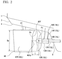
- Fig. 2 is a side view showing the configuration of the propulsion device.
- twin-screw vessel (a ship, a proximity twin-screw vessel) 1 having a stern structure of a single screw vessel type that is a kind of multi-screw vessel is exemplarily described as a ship.
- a propulsion device of the twin-screw vessel 1 of the embodiment includes a starboard propeller 10R, a port propeller 10L and a rudder 40.
- the starboard propeller 10R is installed under a starboard side of the bottom 4 of the stern hull 3 of the ship, that is, the stern of the hull.
- the starboard propeller 10R is connected to one end of a starboard propeller shaft 12R.
- a starboard main engine 18R is installed at a starboard side in the stern hull 3.
- the starboard propeller shaft 12R passes through the stern hull 3 via a bossing 11R formed in the bottom 4 of the ship, and the other end is connected to the starboard main engine 18R.
- the starboard main engine 18R rotates the starboard propeller 10R via the starboard propeller shaft 12R.
- the port propeller 10L is installed under the port side of the bottom 4 of the ship of the stern hull 3.
- the port propeller 10L is connected to one end of a port propeller shaft 12L.
- a port main engine 18L is installed at the port side in the stern hull 3.
- the port propeller shaft 12L passes through the stern hull 3 via a bossing 11 L installed in the bottom 4 of the ship, and the other end is connected to the port main engine 18L.
- the port main engine 18L rotates the port propeller 10L via the port propeller shaft 12L.
- the starboard propeller shaft 12R and the port propeller shaft 12L have rear end sections protruding rearward from the stern hull 3 and rotatably supported by shaft brackets 13R and 13L in front of the starboard propeller 10R and the port propeller 10L.
- the shaft brackets 13R and 13L includes tubular support sections 14R and 14L configured to rotatably support the starboard propeller shaft 12R and the port propeller shaft 12L, and a plurality of struts 15R, 16R, 15L and 16L extending upward from the tubular support sections 14R and 14L in a V shape and having upper ends connected to the bottom 4 of the stern hull 3.
- the starboard propeller 10R and the port propeller 10L are symmetrically disposed with respect to a center C in a vessel widthwise direction to be spaced a distance from each other at which the propeller blades do not interfere with each other. That is, the twin-screw vessel 1 is a type in which the starboard propeller 10R and the port propeller 10L are disposed in parallel, rather than an OLP type or an interlock propeller type.
- a distance between the starboard propeller 10R and the port propeller 10L represents a distance d between propeller tips, which is a gap between the outermost circumferential section of the starboard propeller 10R and the outermost circumferential section of the port propeller 10L at the center C side in the vessel widthwise direction.
- the distance d between the propeller tips may be set to be as small as possible while still avoiding any risk of contact between the propeller blades such that the starboard propeller 10R and the port propeller 10L are disposed to approach the vicinity of the center C in the vessel widthwise direction to capture the longitudinal vortex.
- the distance d between the propeller tips is determined as follows.
- the twin-screw vessel 1 is a type in which the starboard propeller 10R and the port propeller 10L are arranged in parallel
- the distance d between the propeller tips is set to be larger than 0 m.
- the distance d between the propeller tips may be equal to or larger than 0.1 m. This is so that the starboard propeller 10R and the port propeller 10L do not interfere with each other even when a machining error or an assembly error is considered.
- the distance d between the propeller tips is preferably set to be equal to or less than 1.0 m, and more preferably equal to or less than 0.5 m. This is because reducing the distance d between the propeller tips as much as possible allows the longitudinal vortex close to the center C in the vessel widthwise direction to be captured and the propulsion performance to be further improved.
- Fig. 3 is a graph showing a relation between the distance d between the propeller tips of both of the port and the starboard of the ship, and the propulsion performance of the ship of the first embodiment of the present invention.
- a lateral axis shows a value of the distance d between the propeller tips of the starboard propeller 10R and the port propeller 10L.
- a longitudinal axis is a propulsion performance index of the ship, and shows a value standardized by setting the propulsion performance as 1.0 when the single screw vessel propelled by a set of the propeller and the main engine is provided at the same stern hull 3.
- the propulsion performance is horsepower performance, and performance becomes better as horsepower required for outputting the same speed is reduced, i.e., fuel efficiency becomes better.
- lower numerical values of the propulsion performance index indicate better propulsion performance, and higher numerical values indicate worse propulsion performance.
- the propulsion performance should be equal to or less than 1.0. Accordingly, an upper limit of the distance d between the propeller tips may be set to 1.0 m.
- Fig. 4 is a conceptual view schematically showing a relation among the starboard propeller 10R, the port propeller 10L and the vortex.
- longitudinal vortices V2 and V1 are generated in a region 80 in the vicinity of the center C in the vessel widthwise direction.
- a rotational direction of the starboard propeller 10R and the port propeller 10L of the twin-screw vessel becomes outer tracks R2 and R1 that rotate outward from the center C in the vessel widthwise direction over the starboard propeller 10R and the port propeller 10L.
- the starboard propeller 10R and the port propeller 10L can efficiently recover the longitudinal vortices V1 and V2 within regions S2 and S1 overlapping the region 80. Then, since an area obtained by summing the region S2 and the region S1 is increased as the distance d between the propeller tips is reduced, the propulsion performance can be further improved.
- central heights of the starboard propeller 10R and the port propeller 10L may not be disposed at the same position. However, the central heights may be disposed at the same position in consideration of controllability of the twin-screw vessel 1.
- front end sections 9 at the same heights as the starboard propeller 10R and the port propeller 10L of the stern hull 3 may be disposed closer to the bow side than the positions of the ends of the rotational surfaces of the starboard propeller 10R and the port propeller 10L near the bow side.
- the rudder 40 is installed on the center C in the vessel widthwise direction in rear of the starboard propeller 10R and the port propeller 10L.
- the rudder 40 is disposed closer to the rear side (the stern side) than the starboard propeller 10R and the port propeller 10L.
- the rudder 40 has a blade-shaped cross-sectional shape, and is attached to a rudder shaft 41 extending from the bottom 4 of the ship of the stern hull 3 in a vertical downward direction.
- the rudder 40 is rotated about the vertical axis together with the rudder shaft 41, and changes a course direction of the twin-screw vessel 1.
- a front edge 40f of the rudder 40, the starboard propeller 10R and the port propeller 10L may come as close to one another as possible. This is because rapid flows generated by the starboard propeller 10R and the port propeller 10L enter the rudder 40, and thus the control effectiveness of the rudder is improved.
- a propeller diameter of the starboard propeller 10R and the port propeller 10L is Dp
- a distance L between a central position Pc of the starboard propeller 10R and the port propeller 10L and a front edge 40fp of the rudder 40 at a central height Ph of the starboard propeller 10R and the port propeller 10L may be equal to or less than 1.0 Dp.
- the propulsion device for the proximity twin-screw vessel having the shaft bracket and the ship of the above-mentioned first embodiment, since the starboard propeller 10R and the port propeller 10L are disposed to approach the vicinity of the center C in the vessel widthwise direction, the longitudinal vortex in the vicinity of the center C in the vessel widthwise direction can be efficiently recovered, and the propulsion performance can be improved.
- the starboard propeller 10R and the port propeller 10L do not interfere with each other like the interlock propeller type. Accordingly, the twin-screw vessel 1 can be easily manufactured.
- the propulsion performance can be further improved while suppressing generation of cavitation, erosion, or the like.
- auxiliary section resistance can be suppressed to be small. This can also contribute to improvement of the propulsion performance.
- the distance L between the central position Pc of the port propeller 10L and the starboard propeller 10R, and the front edge 40fp of the rudder 40 at the central height Ph of the port propeller 10L and the starboard propeller 10R is set to be equal to or less than 1.0 Dp. Accordingly, the front edge 40fp of the rudder 40 can approach the starboard propeller 10R and the port propeller 10L, and a slip stream can enter the rudder 40 from the starboard propeller 10R and the port propeller 10L. Accordingly, control effectiveness of the rudder can be improved.
- the propulsion device of the twin-screw vessel 1 when the stern hull 3 has a stern structure of the single screw vessel type, the above-mentioned effect can be particularly remarkably exhibited. Further, the stern structure of the single screw vessel type can strengthen the longitudinal vortex turning inward in the vicinity of the center C in the vessel widthwise direction in comparison with the case in which a skeg serving as the stern structure of the twin-screw vessel type is provided, and in the starboard propeller 10R and the port propeller 10L that rotate along the outer track, the flow can be efficiently recovered to improve the propulsion performance.
- the embodiment is not limited thereto.
- the skeg extending along the center C in the vessel widthwise direction may be provided in front of the rudder 40.
- Fig. 5 is a bottom view showing a configuration of the propulsion device of the proximity twin-screw vessel having the shaft bracket of the second embodiment of the present invention.
- Fig. 6 is an enlarged view of a major part of Fig. 5 , showing a cross-sectional shape of a strut of a shaft bracket.
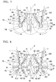
- Fig. 7 is a view of the propulsion device of the proximity twin-screw vessel having the shaft bracket of the second embodiment of the present invention when seen from a rear side.
- the twin-screw vessel 1 includes the starboard propeller 10R, the port propeller 10L and the rudder 40 provided with the same configuration as in the first embodiment.
- the starboard propeller shaft 12R and the port propeller shaft 12L are rotatably supported by the shaft brackets 13R and 13L in front of the starboard propeller 10R and the port propeller 10L.
- struts 25R, 26R, 25L and 26L of the shaft brackets 13R and 13L have a blade-shaped cross-sectional shape perpendicular to a direction extending from the bottom 4 of the ship toward the tubular support sections 14R and 14L.
- the struts 25R, 26R, 25L and 26L are formed to provide flows in an opposite direction of the rotational direction of the starboard propeller 10R and the port propeller 10L in the upper sections of the starboard propeller 10R and the port propeller 10L.
- the starboard propeller 10R and the port propeller 10L are rotated along the outer tracks R2 and R1 outward from the center C in the vessel widthwise direction over the starboard propeller 10R and the port propeller 10L.
- the struts 25R, 26R, 25L and 26L are installed to generate flows FR1 and FL1 from the outside in the vessel widthwise direction toward the center C in the vessel widthwise direction over the starboard propeller 10R and the port propeller 10L.
- the struts 25R, 26R, 25L and 26L are formed to be inclined from front edge sections 25f and 26f toward rear edge sections 25r and 26r to gradually approach the center C in the vessel widthwise direction from a propeller shaft direction Sp.
- the struts 25R, 26R, 25L and 26L of the shaft brackets 13R and 13L have a blade-shaped cross-sectional shape, and the flows FR1 and FL1 from the outside in the vessel widthwise direction opposite to the rotational direction of the starboard propeller 10R and the port propeller 10L are provided in the upper sections of the starboard propeller 10R and the port propeller 10L rotating along the outer tracks R2 and R1 toward the center C in the vessel widthwise direction. Accordingly, a velocity in the rotational direction of the flows of the port propeller 10L and the starboard propeller 10R is relatively increased.
- the slip stream that passes the struts 25R, 26R, 25L and 26L of the shaft brackets 13R and 13L can be efficiently recovered by the starboard propeller 10R and the port propeller 10L, and the propulsion performance can be improved.
- the propulsion device for the twin-screw vessel 1 like the first embodiment, since the starboard propeller 10R and the port propeller 10L are disposed in the vicinity of the center C in the vessel widthwise direction, the longitudinal vortex in the vicinity of the center C in the vessel widthwise direction can be efficiently recovered, and the propulsion performance can be improved.
- the starboard propeller 10R and the port propeller 10L do not interfere with each other like the interlock propeller type. Accordingly, the twin-screw vessel 1 can be easily manufactured.
- the propulsion performance can be improved while suppressing cavitation, erosion, or the like.
- the propeller shaft direction Sp may be inclined with respect to the center C in the vessel widthwise direction, and the starboard propeller shaft 12R and the port propeller shaft 12L or the port main engine 18L and the starboard main engine 18R may be disposed such that a distance between the starboard propeller shaft 12R and the port propeller shaft 12L is gradually reduced toward the rear of the hull to have a horizontal rake.
- Fig. 8 is a view of the propulsion device of the proximity twin-screw vessel having the shaft bracket of the third embodiment of the present invention, when seen from a rear side.
- the twin-screw vessel 1 includes the starboard propeller 10R, the port propeller 10L and the rudder 40 provided with the same configuration as in the second embodiment.
- the starboard propeller shaft 12R and the port propeller shaft 12L are rotatably supported by the shaft brackets 13R and 13L in front of the starboard propeller 10R and the port propeller 10L.
- the tubular support sections 14R and 14L of the shaft brackets 13R and 13L include one or more (in the embodiment, four) fins 45 extending in a radial direction and formed at outer circumferential sections of lower sections thereof.
- the fins 45 have a blade-shaped cross-sectional shape perpendicular to a direction extending from the tubular support sections 14R and 14L toward the outer circumference. Further, the fins 45 are formed to provide flows in an opposite direction of the rotational direction of the starboard propeller 10R and the port propeller 10L in the lower sections of the starboard propeller 10R and the port propeller 10L. That is, the starboard propeller 10R and the port propeller 10L are rotated from the outside toward the center C in the vessel widthwise direction under the starboard propeller 10R and the port propeller 10L.
- the fins 45 are formed to generate flows FR2 and FL2 from the center C in the vessel widthwise direction outward in the vessel widthwise direction under the starboard propeller 10R and the port propeller 10L.
- the fins 45 are formed to be inclined from a front edge section 45f toward a rear edge section 45r and to gradually go away from the center C in the vessel widthwise direction outward in the vessel widthwise direction under the starboard propeller 10R and the port propeller 10L.
- the fins 45 installed at the shaft brackets 13R and 13L have a blade-shaped cross-sectional shape, and the flows FR2 and FL2 having a vortex shape from the center C in the vessel widthwise direction in an opposite direction of the rotational direction of the starboard propeller 10R and the port propeller 10L outward in the vessel widthwise direction can be provided in the lower sections of the starboard propeller 10R and the port propeller 10L. Accordingly, a velocity in the rotational direction of the flows of the port propeller 10L and the starboard propeller 10R is relatively increased. As a result, the slip stream that passes the fins 45 of the shaft brackets 13R and 13L can be efficiently recovered by the starboard propeller 10R and the port propeller 10L, and the propulsion performance can be improved.
- the propulsion device for the twin-screw vessel 1 like the first and second embodiments, since the starboard propeller 10R and the port propeller 10L are disposed to approach the vicinity of the center C in the vessel widthwise direction, the longitudinal vortex in the vicinity of the center C in the vessel widthwise direction can be efficiently recovered, and the propulsion performance can be improved.
- the starboard propeller 10R and the port propeller 10L do not interfere with each other like the interlock propeller type. Accordingly, the twin-screw vessel 1 can be easily manufactured.
- the propulsion performance can be improved while suppressing cavitation, erosion, or the like.
- the embodiment is not limited thereto but the same struts 15R, 16R, 15L and 16L as in the first embodiment may be provided.
- the present invention is not limited to the above-mentioned embodiments but various modifications may be added to the above-mentioned embodiments without departing from the scope of the present invention. That is, the specific shapes, configurations, and so on, are exemplarily mentioned in the embodiments and may be appropriately modified.
Landscapes
- Chemical & Material Sciences (AREA)
- Engineering & Computer Science (AREA)
- Combustion & Propulsion (AREA)
- Mechanical Engineering (AREA)
- Ocean & Marine Engineering (AREA)
- Sliding-Contact Bearings (AREA)
- Physics & Mathematics (AREA)
- Fluid Mechanics (AREA)
- Structures Of Non-Positive Displacement Pumps (AREA)
Abstract
Description
- The present invention relates to a propulsion device for a proximity twin-screw vessel having a shaft bracket, and a ship.
- Priority is claimed on Japanese Patent Application
2014-233258, filed November 18,2014 - A propulsion device of a ship generally obtains a propulsive force by rotating a propeller using a main engine.
- In the case of a ship known as a single screw vessel including one main engine and one propeller, when the ship is increased in size, a load level applied to the one propeller is increased. In order to obtain a sufficient propulsive force, a rotational speed of the propeller should be increased or a diameter of the propeller should be increased. Accordingly, since a circumferential speed of the propeller is increased, a pressure in the vicinity of a propeller blade end is lowered, and cavitation that is a phenomenon in which bubbles are generated in water may excessively occur. When cavitation occurs, the hull is vibrated through the stern and the bottom of the ship. In addition, erosion occurs in the propeller due to the cavitation and exerts a bad influence on durability of the propeller.
- Here, it is known that the above-mentioned problems can be solved in a ship known as a twin-screw vessel including two main engines and two propellers. In a twin-screw vessel, a load level per propeller can be reduced to improve propeller efficiency, and cavitation can be suppressed.
- As examples in which two propellers are disposed at the stern, an overlapping propeller (OLP) type, an interlock propeller type, a type in which propellers are arranged at left and right sides in parallel, and so on, are provided.
- Among these, in the OLP type, the two propellers are disposed to be deviated at front and rear sides thereof, and at least portions of the two propellers when seen from the stern are disposed to overlap each other. The propulsion performance can be improved by 5 to 10% than the single screw vessel by employing the OLP type.
- In the interlock propeller type, a blade of the other propeller is disposed to enter between blades of one propeller.
- In the type in which the propellers are arranged at left and right sides in parallel, the propellers are disposed at the same position in a vessel longitudinal direction in parallel.
- [Patent Literature 1] PCT International Publication No.
WO2006/095774 - However, when the OLP type is used, the propeller disposed at the rear side alternately passes through a fast flow accelerated by the front propeller and a slow flow in the vicinity of a center in a vessel widthwise direction (a widthwise direction of the vessel) during one rotation. For this reason, a load applied to propeller blades of the rear propeller is largely varied. As a result, in the twin-screw vessel using the OLP type, in comparison with the single screw vessel, a bearing force applied to a bearing of a propeller shaft of the rear propeller may become excessive.
- In addition, since a rotational flow having a high velocity is newly formed by rotation of the front propeller, the rear propeller should be operated in an extremely complicated flow, which widens a range in which cavitation occurs. As a result, excessive vibration may be generated. Further, when tip vortex cavitation (blade end vortex cavitation) occurs from front ends of propeller blades of the front propeller, erosion may occur in the propeller blades due to burst of the generated bubbles on propeller blade surfaces of the rear propeller.
- In addition, in the case of the interlock propeller type, rotation of both of the propellers should be controlled such that the blades of one propeller and the blades of the other propeller do not interfere with each other and roll control becomes difficult. In addition, in the worst case, when the blades of one propeller interfere with the blades of the other propeller, the propeller may be damaged.
- The present invention is directed to provide a propulsion device for a proximity twin-screw vessel having a shaft bracket and a ship that are capable of improving propulsion performance while suppressing cavitation, erosion, or the like.
- According to a first aspect of the present invention, there is provided a propulsion device for a proximity twin-screw vessel having a shaft bracket, the propulsion device includes: a port propeller and a starboard propeller installed at a stern hull; one rudder disposed at a center in a vessel widthwise direction of the stern hull or two rudders constituted by a port rudder and a starboard rudder in rear of the port propeller and the starboard propeller; and shaft brackets installed in front of the port propeller and the starboard propeller, respectively, and configured to rotatably support propeller shafts of the port propeller and the starboard propeller, wherein a distance between a tip end of a propeller blade of the port propeller and a tip end of a propeller blade of the starboard propeller at a center in the vessel widthwise direction is larger than 0 m and equal to or smaller than 1.0 m, and a rotational direction of the port propeller and the starboard propeller becomes an outer track rotating from the center in the vessel widthwise direction toward the outside over the port propeller and the starboard propeller.
- In this way, since the starboard propeller and the port propeller are disposed to approach the vicinity of the center in the vessel widthwise direction (referred to as the proximity twin-screw type), a longitudinal vortex in the vicinity of the center in the vessel widthwise direction can be efficiently recovered, and propulsion performance can be improved. In addition, the starboard propeller and the port propeller do not interfere with each other like an interlock propeller. Then, since the starboard propeller and the port propeller are disposed in parallel, in comparison with the OLP type, risks such as an excessive bearing force in the rear propeller, expansion of a cavitation range, erosion, can be largely suppressed.
- In the propulsion device for the proximity twin-screw vessel having the shaft bracket, provided that propeller diameters of the port propeller and the starboard propeller are Dp, a distance between a central position of the port propeller and the starboard propeller and a front edge of the rudder at a central height of the port propeller and the starboard propeller may be equal to or less than 1.0 Dp.
- According to the above-mentioned configuration, a front edge of the rudder can approach the starboard propeller and the port propeller, and a slip stream from the starboard propeller and the port propeller can securely abut a rudder surface. Accordingly, control effectiveness of the rudder and propulsion performance can be improved.
- In the propulsion device for the proximity twin-screw vessel having the shaft bracket, the stern hull may be a stern structure of a single screw vessel type.
- According to the above-mentioned configuration, when the stern structure of the single screw vessel type is provided, an effect of the above-mentioned aspects can be particularly remarkably exhibited. In addition, in the stern structure of the single screw vessel type, in comparison with the case in which a skeg serving as the stern structure of the twin-screw vessel type is provided, a longitudinal vortex turning inward in the vicinity of the center in the vessel widthwise direction can be strengthened, and in the starboard propeller and the port propeller rotating along the outer track, the flow can be efficiently recovered and the propulsion performance can be improved.
- In the propulsion device for the proximity twin-screw vessel having the shaft bracket, the shaft bracket may include a shaft support section configured to rotatably support the propeller shafts of the port propeller and the starboard propeller, and a strut configured to connect the shaft support section and the stern hull, and the strut may be formed to provide flows in an opposite direction of a rotational direction of the port propeller and the starboard propeller in upper sections of the port propeller and the starboard propeller.
- According to the above-mentioned configuration, since flows in an opposite direction of the rotational direction of the port propeller and the starboard propeller are provided by the strut, a velocity in the rotational direction of the flows of the port propeller and the starboard propeller (10R) is relatively increased. Accordingly, in the starboard propeller (10R) and the port propeller, forward thrust can be further exhibited, and the propulsion performance can be improved.
- In the propulsion device for the proximity twin-screw vessel having the shaft bracket, the shaft bracket may include a shaft support section configured to rotatably support the propeller shafts of the port propeller and the starboard propeller, and a strut configured to connect the shaft support section and the stern hull, the shaft support section may include one or more fins radially extending from an outer circumferential section of a lower section thereof, and each of the fins may be formed to provide flows in an opposite direction of a rotational direction of the port propeller and the starboard propeller in lower sections of the port propeller and the starboard propeller.
- According to the above-mentioned configuration, since the flows in the opposite direction of the rotational direction of the port propeller and the starboard propeller are provided by the fins, a velocity in the rotational direction of the flows of the port propeller and the starboard propeller is relatively increased. Accordingly, in the starboard propeller and the port propeller, forward thrust can be further exhibited, and the propulsion performance can be improved.
- According to a second aspect of the present invention, a ship includes the propulsion device for the proximity twin-screw vessel having the shaft bracket according to any one of the above-mentioned aspects.
- According to the above-mentioned configuration, as the starboard propeller and the port propeller are disposed to approach the vicinity of the center in the vessel widthwise direction, the propulsion performance can be improved. Risks such as generation of a bearing force, cavitation, erosion, and so on, in the starboard propeller and the port propeller can be largely suppressed.
- According to the propulsion device for the proximity twin-screw vessel having the shaft bracket and the ship of the present invention, the propulsion performance can be improved while suppressing cavitation, erosion, or the like.
-
-
Fig. 1 is a bottom view showing a configuration of a propulsion device for a proximity twin-screw vessel having a shaft bracket of a first embodiment of the present invention. -
Fig. 2 is a side view showing a configuration of the propulsion device. -
Fig. 3 is a graph showing a relation between a distance d between the propeller tips of both of the port and the starboard of the ship, and propulsion performance of the ship. -
Fig. 4 is a conceptual view when the propulsion device is seen from a rear side, schematically showing a relation among a starboard propeller, a port propeller and a vortex. -
Fig. 5 is a bottom view showing a configuration of a propulsion device for a proximity twin-screw vessel having a shaft bracket of a second embodiment of the present invention. -
Fig. 6 is an enlarged view of a major part ofFig. 5 , showing a cross-sectional shape of a strut of a shaft bracket. -
Fig. 7 is a view of the propulsion device for the proximity twin-screw vessel having the shaft bracket of the second embodiment of the present invention when seen from a rear side. -
Fig. 8 is a view of a propulsion device for a proximity twin-screw vessel having a shaft bracket of a third embodiment of the present invention when seen from a rear side. - Hereinafter, a propulsion device for a proximity twin-screw vessel having a shaft bracket and a ship of an embodiment of the present invention will be described with reference to the accompanying drawings.
-
Fig. 1 is a bottom view showing a configuration of a propulsion device for a proximity twin-screw vessel having a shaft bracket of a first embodiment.Fig. 2 is a side view showing the configuration of the propulsion device. - Here, a twin-screw vessel (a ship, a proximity twin-screw vessel) 1 having a stern structure of a single screw vessel type that is a kind of multi-screw vessel is exemplarily described as a ship.
- As shown in
Fig. 1 , a propulsion device of the twin-screw vessel 1 of the embodiment includes astarboard propeller 10R, aport propeller 10L and arudder 40. - The
starboard propeller 10R is installed under a starboard side of thebottom 4 of thestern hull 3 of the ship, that is, the stern of the hull. Thestarboard propeller 10R is connected to one end of astarboard propeller shaft 12R. A starboardmain engine 18R is installed at a starboard side in thestern hull 3. Thestarboard propeller shaft 12R passes through thestern hull 3 via abossing 11R formed in thebottom 4 of the ship, and the other end is connected to the starboardmain engine 18R. The starboardmain engine 18R rotates thestarboard propeller 10R via thestarboard propeller shaft 12R. - The
port propeller 10L is installed under the port side of thebottom 4 of the ship of thestern hull 3. Theport propeller 10L is connected to one end of aport propeller shaft 12L. A portmain engine 18L is installed at the port side in thestern hull 3. Theport propeller shaft 12L passes through thestern hull 3 via a bossing 11 L installed in thebottom 4 of the ship, and the other end is connected to the portmain engine 18L. The portmain engine 18L rotates theport propeller 10L via theport propeller shaft 12L. - As shown in
Figs. 1 and2 , thestarboard propeller shaft 12R and theport propeller shaft 12L have rear end sections protruding rearward from thestern hull 3 and rotatably supported byshaft brackets starboard propeller 10R and theport propeller 10L. - The
shaft brackets tubular support sections starboard propeller shaft 12R and theport propeller shaft 12L, and a plurality ofstruts tubular support sections bottom 4 of thestern hull 3. - The
starboard propeller 10R and theport propeller 10L are symmetrically disposed with respect to a center C in a vessel widthwise direction to be spaced a distance from each other at which the propeller blades do not interfere with each other. That is, the twin-screw vessel 1 is a type in which thestarboard propeller 10R and theport propeller 10L are disposed in parallel, rather than an OLP type or an interlock propeller type. - Here, a distance between the
starboard propeller 10R and theport propeller 10L represents a distance d between propeller tips, which is a gap between the outermost circumferential section of thestarboard propeller 10R and the outermost circumferential section of theport propeller 10L at the center C side in the vessel widthwise direction. The distance d between the propeller tips may be set to be as small as possible while still avoiding any risk of contact between the propeller blades such that thestarboard propeller 10R and theport propeller 10L are disposed to approach the vicinity of the center C in the vessel widthwise direction to capture the longitudinal vortex. The distance d between the propeller tips is determined as follows. - That is, since the twin-
screw vessel 1 is a type in which thestarboard propeller 10R and theport propeller 10L are arranged in parallel, the distance d between the propeller tips is set to be larger than 0 m. The distance d between the propeller tips may be equal to or larger than 0.1 m. This is so that thestarboard propeller 10R and theport propeller 10L do not interfere with each other even when a machining error or an assembly error is considered. - In addition, the distance d between the propeller tips is preferably set to be equal to or less than 1.0 m, and more preferably equal to or less than 0.5 m. This is because reducing the distance d between the propeller tips as much as possible allows the longitudinal vortex close to the center C in the vessel widthwise direction to be captured and the propulsion performance to be further improved.
-
Fig. 3 is a graph showing a relation between the distance d between the propeller tips of both of the port and the starboard of the ship, and the propulsion performance of the ship of the first embodiment of the present invention. - In
Fig. 3 , a lateral axis shows a value of the distance d between the propeller tips of thestarboard propeller 10R and theport propeller 10L. A longitudinal axis is a propulsion performance index of the ship, and shows a value standardized by setting the propulsion performance as 1.0 when the single screw vessel propelled by a set of the propeller and the main engine is provided at the samestern hull 3. Here, the propulsion performance is horsepower performance, and performance becomes better as horsepower required for outputting the same speed is reduced, i.e., fuel efficiency becomes better. Accordingly, lower numerical values of the propulsion performance index indicate better propulsion performance, and higher numerical values indicate worse propulsion performance. Accordingly, in order to improve the propulsion performance in comparison with the single screw vessel, the propulsion performance should be equal to or less than 1.0. Accordingly, an upper limit of the distance d between the propeller tips may be set to 1.0 m. - An example of this will be described below.
Fig. 4 is a conceptual view schematically showing a relation among thestarboard propeller 10R, theport propeller 10L and the vortex. InFig. 4 , longitudinal vortices V2 and V1 are generated in aregion 80 in the vicinity of the center C in the vessel widthwise direction. In order to efficiently recover the longitudinal vortices V2 and V1 of theregion 80 and improve the propulsion performance, a rotational direction of thestarboard propeller 10R and theport propeller 10L of the twin-screw vessel becomes outer tracks R2 and R1 that rotate outward from the center C in the vessel widthwise direction over thestarboard propeller 10R and theport propeller 10L. - The
starboard propeller 10R and theport propeller 10L can efficiently recover the longitudinal vortices V1 and V2 within regions S2 and S1 overlapping theregion 80. Then, since an area obtained by summing the region S2 and the region S1 is increased as the distance d between the propeller tips is reduced, the propulsion performance can be further improved. - In addition, central heights of the
starboard propeller 10R and theport propeller 10L may not be disposed at the same position. However, the central heights may be disposed at the same position in consideration of controllability of the twin-screw vessel 1. - In addition,
front end sections 9 at the same heights as thestarboard propeller 10R and theport propeller 10L of thestern hull 3 may be disposed closer to the bow side than the positions of the ends of the rotational surfaces of thestarboard propeller 10R and theport propeller 10L near the bow side. - The
rudder 40 is installed on the center C in the vessel widthwise direction in rear of thestarboard propeller 10R and theport propeller 10L. - The
rudder 40 is disposed closer to the rear side (the stern side) than thestarboard propeller 10R and theport propeller 10L. Therudder 40 has a blade-shaped cross-sectional shape, and is attached to arudder shaft 41 extending from thebottom 4 of the ship of thestern hull 3 in a vertical downward direction. Therudder 40 is rotated about the vertical axis together with therudder shaft 41, and changes a course direction of the twin-screw vessel 1. - Here, a
front edge 40f of therudder 40, thestarboard propeller 10R and theport propeller 10L may come as close to one another as possible. This is because rapid flows generated by thestarboard propeller 10R and theport propeller 10L enter therudder 40, and thus the control effectiveness of the rudder is improved. Specifically, when a propeller diameter of thestarboard propeller 10R and theport propeller 10L is Dp, a distance L between a central position Pc of thestarboard propeller 10R and theport propeller 10L and a front edge 40fp of therudder 40 at a central height Ph of thestarboard propeller 10R and theport propeller 10L may be equal to or less than 1.0 Dp. - Accordingly, according to the propulsion device for the proximity twin-screw vessel having the shaft bracket and the ship of the above-mentioned first embodiment, since the
starboard propeller 10R and theport propeller 10L are disposed to approach the vicinity of the center C in the vessel widthwise direction, the longitudinal vortex in the vicinity of the center C in the vessel widthwise direction can be efficiently recovered, and the propulsion performance can be improved. In addition, thestarboard propeller 10R and theport propeller 10L do not interfere with each other like the interlock propeller type. Accordingly, the twin-screw vessel 1 can be easily manufactured. Then, since thestarboard propeller 10R and theport propeller 10L are disposed in parallel, in comparison with the OLP type, risks such as an excessive bearing force of the rear-side propeller, expansion of a cavitation range, erosion, can be largely suppressed. - In this way, according to the twin-
screw vessel 1, the propulsion performance can be further improved while suppressing generation of cavitation, erosion, or the like. - In addition, as
propeller shafts shaft brackets - In addition, according to the propulsion device of the twin-
screw vessel 1, the distance L between the central position Pc of theport propeller 10L and thestarboard propeller 10R, and the front edge 40fp of therudder 40 at the central height Ph of theport propeller 10L and thestarboard propeller 10R is set to be equal to or less than 1.0 Dp. Accordingly, the front edge 40fp of therudder 40 can approach thestarboard propeller 10R and theport propeller 10L, and a slip stream can enter therudder 40 from thestarboard propeller 10R and theport propeller 10L. Accordingly, control effectiveness of the rudder can be improved. - In addition, according to the propulsion device of the twin-
screw vessel 1, when thestern hull 3 has a stern structure of the single screw vessel type, the above-mentioned effect can be particularly remarkably exhibited. Further, the stern structure of the single screw vessel type can strengthen the longitudinal vortex turning inward in the vicinity of the center C in the vessel widthwise direction in comparison with the case in which a skeg serving as the stern structure of the twin-screw vessel type is provided, and in thestarboard propeller 10R and theport propeller 10L that rotate along the outer track, the flow can be efficiently recovered to improve the propulsion performance. - Further, in the first embodiment, while the
stern hull 3 of the twin-screw vessel 1 has the stern structure of the single screw vessel type, the embodiment is not limited thereto. In thestern hull 3, the skeg extending along the center C in the vessel widthwise direction may be provided in front of therudder 40. - Next, a second embodiment of the propulsion device for the proximity twin-screw vessel having the shaft bracket and the ship according to the present invention will be described. Since the second embodiment to be described below is different from the first embodiment only in the configurations of the
shaft brackets -
Fig. 5 is a bottom view showing a configuration of the propulsion device of the proximity twin-screw vessel having the shaft bracket of the second embodiment of the present invention.Fig. 6 is an enlarged view of a major part ofFig. 5 , showing a cross-sectional shape of a strut of a shaft bracket.Fig. 7 is a view of the propulsion device of the proximity twin-screw vessel having the shaft bracket of the second embodiment of the present invention when seen from a rear side. - As shown in
Figs. 5 ,6 and7 , the twin-screw vessel 1 according to the embodiment includes thestarboard propeller 10R, theport propeller 10L and therudder 40 provided with the same configuration as in the first embodiment. - The
starboard propeller shaft 12R and theport propeller shaft 12L are rotatably supported by theshaft brackets starboard propeller 10R and theport propeller 10L. Further, in the embodiment, struts 25R, 26R, 25L and 26L of theshaft brackets bottom 4 of the ship toward thetubular support sections struts starboard propeller 10R and theport propeller 10L in the upper sections of thestarboard propeller 10R and theport propeller 10L. That is, thestarboard propeller 10R and theport propeller 10L are rotated along the outer tracks R2 and R1 outward from the center C in the vessel widthwise direction over thestarboard propeller 10R and theport propeller 10L. Here, thestruts starboard propeller 10R and theport propeller 10L. Specifically, thestruts front edge sections rear edge sections - Accordingly, according to the propulsion device for the proximity twin-screw vessel having the shaft bracket and the ship of the above-mentioned second embodiment, the
struts shaft brackets starboard propeller 10R and theport propeller 10L are provided in the upper sections of thestarboard propeller 10R and theport propeller 10L rotating along the outer tracks R2 and R1 toward the center C in the vessel widthwise direction. Accordingly, a velocity in the rotational direction of the flows of theport propeller 10L and thestarboard propeller 10R is relatively increased. As a result, the slip stream that passes thestruts shaft brackets starboard propeller 10R and theport propeller 10L, and the propulsion performance can be improved. - In addition, according to the propulsion device for the twin-
screw vessel 1, like the first embodiment, since thestarboard propeller 10R and theport propeller 10L are disposed in the vicinity of the center C in the vessel widthwise direction, the longitudinal vortex in the vicinity of the center C in the vessel widthwise direction can be efficiently recovered, and the propulsion performance can be improved. In addition, thestarboard propeller 10R and theport propeller 10L do not interfere with each other like the interlock propeller type. Accordingly, the twin-screw vessel 1 can be easily manufactured. Then, since thestarboard propeller 10R and theport propeller 10L are disposed in parallel, in comparison with the OLP type, risks such as an excessive bearing force in the rear-side propeller, expansion of a cavitation range, erosion, can be largely suppressed. - In this way, according to the twin-
screw vessel 1, the propulsion performance can be improved while suppressing cavitation, erosion, or the like. - As shown in
Figs. 5 and6 , in the configuration of the embodiment, the propeller shaft direction Sp may be inclined with respect to the center C in the vessel widthwise direction, and thestarboard propeller shaft 12R and theport propeller shaft 12L or the portmain engine 18L and the starboardmain engine 18R may be disposed such that a distance between thestarboard propeller shaft 12R and theport propeller shaft 12L is gradually reduced toward the rear of the hull to have a horizontal rake. - Next, a third embodiment of the propulsion device for the proximity twin-screw vessel having the shaft bracket and the ship according to the present invention will be described. Since the third embodiment to be described below is different from the second embodiment only in the configurations of the
shaft brackets -
Fig. 8 is a view of the propulsion device of the proximity twin-screw vessel having the shaft bracket of the third embodiment of the present invention, when seen from a rear side. - As shown in
Fig. 8 , the twin-screw vessel 1 according to the embodiment includes thestarboard propeller 10R, theport propeller 10L and therudder 40 provided with the same configuration as in the second embodiment. - The
starboard propeller shaft 12R and theport propeller shaft 12L are rotatably supported by theshaft brackets starboard propeller 10R and theport propeller 10L. In the embodiment, thetubular support sections shaft brackets fins 45 extending in a radial direction and formed at outer circumferential sections of lower sections thereof. - The
fins 45 have a blade-shaped cross-sectional shape perpendicular to a direction extending from thetubular support sections fins 45 are formed to provide flows in an opposite direction of the rotational direction of thestarboard propeller 10R and theport propeller 10L in the lower sections of thestarboard propeller 10R and theport propeller 10L. That is, thestarboard propeller 10R and theport propeller 10L are rotated from the outside toward the center C in the vessel widthwise direction under thestarboard propeller 10R and theport propeller 10L. Here, thefins 45 are formed to generate flows FR2 and FL2 from the center C in the vessel widthwise direction outward in the vessel widthwise direction under thestarboard propeller 10R and theport propeller 10L. Specifically, thefins 45 are formed to be inclined from afront edge section 45f toward arear edge section 45r and to gradually go away from the center C in the vessel widthwise direction outward in the vessel widthwise direction under thestarboard propeller 10R and theport propeller 10L. - Accordingly, according to the propulsion device for the proximity twin-screw vessel having the shaft bracket and the ship of the above-mentioned third embodiment, the
fins 45 installed at theshaft brackets starboard propeller 10R and theport propeller 10L outward in the vessel widthwise direction can be provided in the lower sections of thestarboard propeller 10R and theport propeller 10L. Accordingly, a velocity in the rotational direction of the flows of theport propeller 10L and thestarboard propeller 10R is relatively increased. As a result, the slip stream that passes thefins 45 of theshaft brackets starboard propeller 10R and theport propeller 10L, and the propulsion performance can be improved. - In addition, according to the propulsion device for the twin-
screw vessel 1, like the first and second embodiments, since thestarboard propeller 10R and theport propeller 10L are disposed to approach the vicinity of the center C in the vessel widthwise direction, the longitudinal vortex in the vicinity of the center C in the vessel widthwise direction can be efficiently recovered, and the propulsion performance can be improved. In addition, thestarboard propeller 10R and theport propeller 10L do not interfere with each other like the interlock propeller type. Accordingly, the twin-screw vessel 1 can be easily manufactured. Then, since thestarboard propeller 10R and theport propeller 10L are disposed in parallel, in comparison with the OLP type, risks such as an excessive bearing force in the rear-side propeller, expansion of a cavitation range, erosion, can be largely suppressed. - In this way, according to the twin-
screw vessel 1, the propulsion performance can be improved while suppressing cavitation, erosion, or the like. - Further, in the third embodiment, while the
same struts same struts - Further, the present invention is not limited to the above-mentioned embodiments but various modifications may be added to the above-mentioned embodiments without departing from the scope of the present invention. That is, the specific shapes, configurations, and so on, are exemplarily mentioned in the embodiments and may be appropriately modified.
-
- 1
- twin-screw vessel (ship, proximity twin-screw vessel)
- 3
- stern hull
- 4
- bottom of ship
- 9
- front end section
- 10L
- port propeller
- 10R
- starboard propeller
- 11L, 11R
- bossing
- 12L
- port propeller shaft
- 12R
- starboard propeller shaft
- 13R, 13L
- shaft bracket
- 14R, 14L
- tubular support section
- 15R, 15L, 16R, 16L, 25R, 25L, 26R, 26L
- strut
- 18L
- port main engine
- 18R
- starboard main engine
- 40
- rudder
- 40f, 40fp
- front edge
- 41
- rudder shaft
- 45
- fin
- 80
- region
- C
- center of vessel widthwise direction
- D
- distance between propeller tips
- Ls
- reference line
- V1, V2
- longitudinal vortex
Claims (6)
- A propulsion device for a proximity twin-screw vessel having a shaft bracket, the propulsion device comprising:a port propeller and a starboard propeller installed at a stern hull;one rudder disposed at a center in a vessel widthwise direction of the stern hull or two rudders constituted by a port rudder and a starboard rudder in rear of the port propeller and the starboard propeller; andshaft brackets installed in front of the port propeller and the starboard propeller, respectively, and configured to rotatably support propeller shafts of the port propeller and the starboard propeller,wherein a distance between a tip end of a propeller blade of the port propeller and a tip end of a propeller blade of the starboard propeller at a center in the vessel widthwise direction is larger than 0 m and equal to or smaller than 1.0 m, anda rotational direction of the port propeller and the starboard propeller becomes an outer track rotating from the center in the vessel widthwise direction toward the outside over the port propeller and the starboard propeller.
- The propulsion device for the proximity twin-screw vessel having the shaft bracket according to claim 1, wherein, provided that propeller diameters of the port propeller and the starboard propeller are Dp, a distance between a central position of the port propeller and the starboard propeller and a front edge of the rudder at a central height of the port propeller and the starboard propeller is equal to or less than 1.0 Dp.
- The propulsion device for the proximity twin-screw vessel having the shaft bracket according to claim 1 or 2, wherein the stern hull is a stern structure of a single screw vessel type.
- The propulsion device for the proximity twin-screw vessel having the shaft bracket according to any one of claims 1 to 3, wherein the shaft bracket comprises a shaft support section configured to rotatably support the propeller shafts of the port propeller and the starboard propeller, and a strut configured to connect the shaft support section and the stern hull, and
the strut is formed to provide flows in an opposite direction of a rotational direction of the port propeller and the starboard propeller in upper sections of the port propeller and the starboard propeller. - The propulsion device of the proximity twin-screw vessel having the shaft bracket according to any one of claims 1 to 4, wherein the shaft bracket comprises a shaft support section configured to rotatably support the propeller shafts of the port propeller and the starboard propeller, and a strut configured to connect the shaft support section and the stern hull, and
the shaft support section comprises one or more fins radially extending from an outer circumferential section of a lower section thereof, and each of the fins is formed to provide flows in an opposite direction of a rotational direction of the port propeller and the starboard propeller in lower sections of the port propeller and the starboard propeller. - A ship comprising the propulsion device of the proximity twin-screw vessel having the shaft bracket according to any one of claims 1 to 5.
Applications Claiming Priority (2)
| Application Number | Priority Date | Filing Date | Title |
|---|---|---|---|
| JP2014233258A JP6226241B2 (en) | 2014-11-18 | 2014-11-18 | Proximity biaxial ship propulsion device with shaft bracket, ship |
| PCT/JP2015/053372 WO2016080002A1 (en) | 2014-11-18 | 2015-02-06 | Propulsion device for neighboring-twin-screw ship having shaft brackets, and ship |
Publications (3)
| Publication Number | Publication Date |
|---|---|
| EP3045382A1 true EP3045382A1 (en) | 2016-07-20 |
| EP3045382A4 EP3045382A4 (en) | 2017-11-29 |
| EP3045382B1 EP3045382B1 (en) | 2020-08-12 |
Family
ID=56013571
Family Applications (1)
| Application Number | Title | Priority Date | Filing Date |
|---|---|---|---|
| EP15823304.9A Active EP3045382B1 (en) | 2014-11-18 | 2015-02-06 | Propulsion device for neighboring-twin-screw ship having shaft brackets, and ship |
Country Status (6)
| Country | Link |
|---|---|
| US (1) | US20160325810A1 (en) |
| EP (1) | EP3045382B1 (en) |
| JP (1) | JP6226241B2 (en) |
| KR (1) | KR101891006B1 (en) |
| CN (2) | CN105813939A (en) |
| WO (1) | WO2016080002A1 (en) |
Families Citing this family (3)
| Publication number | Priority date | Publication date | Assignee | Title |
|---|---|---|---|---|
| JP6246960B1 (en) * | 2017-01-25 | 2017-12-13 | 三菱重工業株式会社 | Ship propulsion device and ship |
| CN109334925A (en) * | 2018-10-22 | 2019-02-15 | 谭国祯 | Vector push type submarine |
| CN114349111B (en) * | 2021-12-15 | 2025-07-04 | 河北恒特环保工程有限公司 | A mobile floating solar algae removal device and method |
Family Cites Families (11)
| Publication number | Priority date | Publication date | Assignee | Title |
|---|---|---|---|---|
| US2974628A (en) * | 1958-10-20 | 1961-03-14 | Robert W Erlbacher | Twisted strut construction for marine bearing with forwardly mounted propeller |
| JPS4737316B1 (en) * | 1968-10-26 | 1972-09-20 | ||
| JPS59202991A (en) * | 1983-05-02 | 1984-11-16 | Mitsubishi Heavy Ind Ltd | Shaft bracket having slanted wing cross section |
| JPS6072800U (en) * | 1983-10-27 | 1985-05-22 | 三菱重工業株式会社 | Botting structure with fins for multi-shaft ships |
| JPH0315300U (en) * | 1989-06-27 | 1991-02-15 | ||
| EP1892183B8 (en) | 2005-03-11 | 2016-02-24 | Kawasaki Jukogyo Kabushiki Kaisha | Stern structure of ship |
| JP4707569B2 (en) * | 2006-01-17 | 2011-06-22 | 流体テクノ有限会社 | Ship thrust-enhancing shaft bracket |
| US7798875B1 (en) * | 2006-10-20 | 2010-09-21 | Brunswick Corporation | Helical marine strut |
| JP2011098639A (en) * | 2009-11-05 | 2011-05-19 | Mitsubishi Heavy Ind Ltd | Stern structure of marine vessel |
| JP5582761B2 (en) * | 2009-11-09 | 2014-09-03 | 三菱重工業株式会社 | Ship propulsion device |
| JP5281559B2 (en) * | 2009-12-14 | 2013-09-04 | 三菱重工業株式会社 | Ship propulsion performance improvement device |
-
2014
- 2014-11-18 JP JP2014233258A patent/JP6226241B2/en active Active
-
2015
- 2015-02-06 WO PCT/JP2015/053372 patent/WO2016080002A1/en not_active Ceased
- 2015-02-06 KR KR1020167002329A patent/KR101891006B1/en active Active
- 2015-02-06 EP EP15823304.9A patent/EP3045382B1/en active Active
- 2015-02-06 US US14/907,757 patent/US20160325810A1/en not_active Abandoned
- 2015-02-06 CN CN201580001416.8A patent/CN105813939A/en active Pending
- 2015-02-06 CN CN202010248964.3A patent/CN111516841A/en active Pending
Also Published As
| Publication number | Publication date |
|---|---|
| JP6226241B2 (en) | 2017-11-08 |
| EP3045382A4 (en) | 2017-11-29 |
| EP3045382B1 (en) | 2020-08-12 |
| KR101891006B1 (en) | 2018-09-28 |
| JP2016097687A (en) | 2016-05-30 |
| CN105813939A (en) | 2016-07-27 |
| US20160325810A1 (en) | 2016-11-10 |
| KR20160072088A (en) | 2016-06-22 |
| CN111516841A (en) | 2020-08-11 |
| WO2016080002A1 (en) | 2016-05-26 |
Similar Documents
| Publication | Publication Date | Title |
|---|---|---|
| JP7422839B2 (en) | rudder | |
| JP4789953B2 (en) | Ship propulsion system | |
| EP2338783A1 (en) | Twin skeg ship | |
| JP2014040169A (en) | Contra-rotating propeller propulsion system ship | |
| JP2011025918A (en) | Nozzle propeller for vessel | |
| CN113179636A (en) | Steering device | |
| JP6246960B1 (en) | Ship propulsion device and ship | |
| EP3045382B1 (en) | Propulsion device for neighboring-twin-screw ship having shaft brackets, and ship | |
| JP5453625B2 (en) | Ship with biaxial propeller | |
| KR101493561B1 (en) | Propulsion device for ship | |
| JP6554743B2 (en) | Closed biaxial ship with finned rudder, ship | |
| CN101137538B (en) | Stern structure of ship | |
| WO2021014919A1 (en) | Stern fin | |
| JP6493691B2 (en) | Ship | |
| JP2010095239A (en) | Rudder device for marine vessel | |
| CN103796913A (en) | Water vessel propulsion apparatus | |
| KR101159205B1 (en) | Rudder for ship and ship including the same | |
| JP7107668B2 (en) | rudder | |
| JP2005239083A (en) | Pod type propulsion unit and vessel provided with this | |
| JP6345221B2 (en) | Single axis and two rudder system | |
| JP6380848B2 (en) | Ship | |
| JP2011031858A (en) | Pod propelling device | |
| KR102204035B1 (en) | Rudder and ship having the same | |
| KR20140131768A (en) | A rudder for a ship | |
| KR20130053094A (en) | Ship |
Legal Events
| Date | Code | Title | Description |
|---|---|---|---|
| PUAI | Public reference made under article 153(3) epc to a published international application that has entered the european phase |
Free format text: ORIGINAL CODE: 0009012 |
|
| 17P | Request for examination filed |
Effective date: 20160126 |
|
| AK | Designated contracting states |
Kind code of ref document: A1 Designated state(s): AL AT BE BG CH CY CZ DE DK EE ES FI FR GB GR HR HU IE IS IT LI LT LU LV MC MK MT NL NO PL PT RO RS SE SI SK SM TR |
|
| AX | Request for extension of the european patent |
Extension state: BA ME |
|
| R17P | Request for examination filed (corrected) |
Effective date: 20160126 |
|
| RBV | Designated contracting states (corrected) |
Designated state(s): AL AT BE BG CH CY CZ DE DK EE ES FI FR GB GR HR HU IE IS IT LI LT LU LV MC MK MT NL NO PL PT RO RS SE SI SK SM TR |
|
| A4 | Supplementary search report drawn up and despatched |
Effective date: 20171027 |
|
| RIC1 | Information provided on ipc code assigned before grant |
Ipc: B63H 5/16 20060101ALI20171023BHEP Ipc: B63H 5/08 20060101AFI20171023BHEP Ipc: B63B 3/42 20060101ALI20171023BHEP |
|
| DAX | Request for extension of the european patent (deleted) | ||
| STAA | Information on the status of an ep patent application or granted ep patent |
Free format text: STATUS: REQUEST FOR EXAMINATION WAS MADE |
|
| R17P | Request for examination filed (corrected) |
Effective date: 20160126 |
|
| REG | Reference to a national code |
Ref country code: DE Ref legal event code: R079 Ref document number: 602015057460 Country of ref document: DE Free format text: PREVIOUS MAIN CLASS: B63H0005080000 Ipc: B63B0003420000 |
|
| GRAP | Despatch of communication of intention to grant a patent |
Free format text: ORIGINAL CODE: EPIDOSNIGR1 |
|
| STAA | Information on the status of an ep patent application or granted ep patent |
Free format text: STATUS: GRANT OF PATENT IS INTENDED |
|
| RIC1 | Information provided on ipc code assigned before grant |
Ipc: B63B 3/42 20060101AFI20200304BHEP Ipc: B63H 5/16 20060101ALI20200304BHEP Ipc: B63H 5/08 20060101ALI20200304BHEP |
|
| INTG | Intention to grant announced |
Effective date: 20200403 |
|
| GRAS | Grant fee paid |
Free format text: ORIGINAL CODE: EPIDOSNIGR3 |
|
| GRAA | (expected) grant |
Free format text: ORIGINAL CODE: 0009210 |
|
| STAA | Information on the status of an ep patent application or granted ep patent |
Free format text: STATUS: THE PATENT HAS BEEN GRANTED |
|
| AK | Designated contracting states |
Kind code of ref document: B1 Designated state(s): AL AT BE BG CH CY CZ DE DK EE ES FI FR GB GR HR HU IE IS IT LI LT LU LV MC MK MT NL NO PL PT RO RS SE SI SK SM TR |
|
| RAP1 | Party data changed (applicant data changed or rights of an application transferred) |
Owner name: MITSUBISHI HEAVY INDUSTRIES, LTD. |
|
| REG | Reference to a national code |
Ref country code: CH Ref legal event code: EP |
|
| REG | Reference to a national code |
Ref country code: IE Ref legal event code: FG4D |
|
| REG | Reference to a national code |
Ref country code: DE Ref legal event code: R096 Ref document number: 602015057460 Country of ref document: DE |
|
| REG | Reference to a national code |
Ref country code: AT Ref legal event code: REF Ref document number: 1301310 Country of ref document: AT Kind code of ref document: T Effective date: 20200915 |
|
| REG | Reference to a national code |
Ref country code: LT Ref legal event code: MG4D |
|
| REG | Reference to a national code |
Ref country code: NL Ref legal event code: MP Effective date: 20200812 |
|
| PG25 | Lapsed in a contracting state [announced via postgrant information from national office to epo] |
Ref country code: HR Free format text: LAPSE BECAUSE OF FAILURE TO SUBMIT A TRANSLATION OF THE DESCRIPTION OR TO PAY THE FEE WITHIN THE PRESCRIBED TIME-LIMIT Effective date: 20200812 Ref country code: BG Free format text: LAPSE BECAUSE OF FAILURE TO SUBMIT A TRANSLATION OF THE DESCRIPTION OR TO PAY THE FEE WITHIN THE PRESCRIBED TIME-LIMIT Effective date: 20201112 Ref country code: SE Free format text: LAPSE BECAUSE OF FAILURE TO SUBMIT A TRANSLATION OF THE DESCRIPTION OR TO PAY THE FEE WITHIN THE PRESCRIBED TIME-LIMIT Effective date: 20200812 Ref country code: LT Free format text: LAPSE BECAUSE OF FAILURE TO SUBMIT A TRANSLATION OF THE DESCRIPTION OR TO PAY THE FEE WITHIN THE PRESCRIBED TIME-LIMIT Effective date: 20200812 Ref country code: NO Free format text: LAPSE BECAUSE OF FAILURE TO SUBMIT A TRANSLATION OF THE DESCRIPTION OR TO PAY THE FEE WITHIN THE PRESCRIBED TIME-LIMIT Effective date: 20201112 Ref country code: GR Free format text: LAPSE BECAUSE OF FAILURE TO SUBMIT A TRANSLATION OF THE DESCRIPTION OR TO PAY THE FEE WITHIN THE PRESCRIBED TIME-LIMIT Effective date: 20201113 Ref country code: FI Free format text: LAPSE BECAUSE OF FAILURE TO SUBMIT A TRANSLATION OF THE DESCRIPTION OR TO PAY THE FEE WITHIN THE PRESCRIBED TIME-LIMIT Effective date: 20200812 |
|
| REG | Reference to a national code |
Ref country code: AT Ref legal event code: MK05 Ref document number: 1301310 Country of ref document: AT Kind code of ref document: T Effective date: 20200812 |
|
| PG25 | Lapsed in a contracting state [announced via postgrant information from national office to epo] |
Ref country code: IS Free format text: LAPSE BECAUSE OF FAILURE TO SUBMIT A TRANSLATION OF THE DESCRIPTION OR TO PAY THE FEE WITHIN THE PRESCRIBED TIME-LIMIT Effective date: 20201212 Ref country code: RS Free format text: LAPSE BECAUSE OF FAILURE TO SUBMIT A TRANSLATION OF THE DESCRIPTION OR TO PAY THE FEE WITHIN THE PRESCRIBED TIME-LIMIT Effective date: 20200812 Ref country code: NL Free format text: LAPSE BECAUSE OF FAILURE TO SUBMIT A TRANSLATION OF THE DESCRIPTION OR TO PAY THE FEE WITHIN THE PRESCRIBED TIME-LIMIT Effective date: 20200812 Ref country code: LV Free format text: LAPSE BECAUSE OF FAILURE TO SUBMIT A TRANSLATION OF THE DESCRIPTION OR TO PAY THE FEE WITHIN THE PRESCRIBED TIME-LIMIT Effective date: 20200812 Ref country code: PL Free format text: LAPSE BECAUSE OF FAILURE TO SUBMIT A TRANSLATION OF THE DESCRIPTION OR TO PAY THE FEE WITHIN THE PRESCRIBED TIME-LIMIT Effective date: 20200812 |
|
| PG25 | Lapsed in a contracting state [announced via postgrant information from national office to epo] |
Ref country code: CZ Free format text: LAPSE BECAUSE OF FAILURE TO SUBMIT A TRANSLATION OF THE DESCRIPTION OR TO PAY THE FEE WITHIN THE PRESCRIBED TIME-LIMIT Effective date: 20200812 Ref country code: DK Free format text: LAPSE BECAUSE OF FAILURE TO SUBMIT A TRANSLATION OF THE DESCRIPTION OR TO PAY THE FEE WITHIN THE PRESCRIBED TIME-LIMIT Effective date: 20200812 Ref country code: RO Free format text: LAPSE BECAUSE OF FAILURE TO SUBMIT A TRANSLATION OF THE DESCRIPTION OR TO PAY THE FEE WITHIN THE PRESCRIBED TIME-LIMIT Effective date: 20200812 Ref country code: SM Free format text: LAPSE BECAUSE OF FAILURE TO SUBMIT A TRANSLATION OF THE DESCRIPTION OR TO PAY THE FEE WITHIN THE PRESCRIBED TIME-LIMIT Effective date: 20200812 Ref country code: EE Free format text: LAPSE BECAUSE OF FAILURE TO SUBMIT A TRANSLATION OF THE DESCRIPTION OR TO PAY THE FEE WITHIN THE PRESCRIBED TIME-LIMIT Effective date: 20200812 |
|
| REG | Reference to a national code |
Ref country code: DE Ref legal event code: R097 Ref document number: 602015057460 Country of ref document: DE |
|
| PG25 | Lapsed in a contracting state [announced via postgrant information from national office to epo] |
Ref country code: ES Free format text: LAPSE BECAUSE OF FAILURE TO SUBMIT A TRANSLATION OF THE DESCRIPTION OR TO PAY THE FEE WITHIN THE PRESCRIBED TIME-LIMIT Effective date: 20200812 Ref country code: AT Free format text: LAPSE BECAUSE OF FAILURE TO SUBMIT A TRANSLATION OF THE DESCRIPTION OR TO PAY THE FEE WITHIN THE PRESCRIBED TIME-LIMIT Effective date: 20200812 Ref country code: AL Free format text: LAPSE BECAUSE OF FAILURE TO SUBMIT A TRANSLATION OF THE DESCRIPTION OR TO PAY THE FEE WITHIN THE PRESCRIBED TIME-LIMIT Effective date: 20200812 |
|
| PLBE | No opposition filed within time limit |
Free format text: ORIGINAL CODE: 0009261 |
|
| STAA | Information on the status of an ep patent application or granted ep patent |
Free format text: STATUS: NO OPPOSITION FILED WITHIN TIME LIMIT |
|
| PG25 | Lapsed in a contracting state [announced via postgrant information from national office to epo] |
Ref country code: SK Free format text: LAPSE BECAUSE OF FAILURE TO SUBMIT A TRANSLATION OF THE DESCRIPTION OR TO PAY THE FEE WITHIN THE PRESCRIBED TIME-LIMIT Effective date: 20200812 |
|
| 26N | No opposition filed |
Effective date: 20210514 |
|
| PG25 | Lapsed in a contracting state [announced via postgrant information from national office to epo] |
Ref country code: SI Free format text: LAPSE BECAUSE OF FAILURE TO SUBMIT A TRANSLATION OF THE DESCRIPTION OR TO PAY THE FEE WITHIN THE PRESCRIBED TIME-LIMIT Effective date: 20200812 |
|
| PG25 | Lapsed in a contracting state [announced via postgrant information from national office to epo] |
Ref country code: MC Free format text: LAPSE BECAUSE OF FAILURE TO SUBMIT A TRANSLATION OF THE DESCRIPTION OR TO PAY THE FEE WITHIN THE PRESCRIBED TIME-LIMIT Effective date: 20200812 |
|
| GBPC | Gb: european patent ceased through non-payment of renewal fee |
Effective date: 20210206 |
|
| REG | Reference to a national code |
Ref country code: BE Ref legal event code: MM Effective date: 20210228 |
|
| PG25 | Lapsed in a contracting state [announced via postgrant information from national office to epo] |
Ref country code: LU Free format text: LAPSE BECAUSE OF NON-PAYMENT OF DUE FEES Effective date: 20210206 Ref country code: LI Free format text: LAPSE BECAUSE OF NON-PAYMENT OF DUE FEES Effective date: 20210228 Ref country code: CH Free format text: LAPSE BECAUSE OF NON-PAYMENT OF DUE FEES Effective date: 20210228 |
|
| PG25 | Lapsed in a contracting state [announced via postgrant information from national office to epo] |
Ref country code: GB Free format text: LAPSE BECAUSE OF NON-PAYMENT OF DUE FEES Effective date: 20210206 Ref country code: FR Free format text: LAPSE BECAUSE OF NON-PAYMENT OF DUE FEES Effective date: 20210228 Ref country code: IE Free format text: LAPSE BECAUSE OF NON-PAYMENT OF DUE FEES Effective date: 20210206 |
|
| PG25 | Lapsed in a contracting state [announced via postgrant information from national office to epo] |
Ref country code: BE Free format text: LAPSE BECAUSE OF NON-PAYMENT OF DUE FEES Effective date: 20210228 |
|
| PG25 | Lapsed in a contracting state [announced via postgrant information from national office to epo] |
Ref country code: PT Free format text: LAPSE BECAUSE OF FAILURE TO SUBMIT A TRANSLATION OF THE DESCRIPTION OR TO PAY THE FEE WITHIN THE PRESCRIBED TIME-LIMIT Effective date: 20201214 |
|
| PG25 | Lapsed in a contracting state [announced via postgrant information from national office to epo] |
Ref country code: HU Free format text: LAPSE BECAUSE OF FAILURE TO SUBMIT A TRANSLATION OF THE DESCRIPTION OR TO PAY THE FEE WITHIN THE PRESCRIBED TIME-LIMIT; INVALID AB INITIO Effective date: 20150206 |
|
| PG25 | Lapsed in a contracting state [announced via postgrant information from national office to epo] |
Ref country code: CY Free format text: LAPSE BECAUSE OF FAILURE TO SUBMIT A TRANSLATION OF THE DESCRIPTION OR TO PAY THE FEE WITHIN THE PRESCRIBED TIME-LIMIT Effective date: 20200812 |
|
| PG25 | Lapsed in a contracting state [announced via postgrant information from national office to epo] |
Ref country code: MK Free format text: LAPSE BECAUSE OF FAILURE TO SUBMIT A TRANSLATION OF THE DESCRIPTION OR TO PAY THE FEE WITHIN THE PRESCRIBED TIME-LIMIT Effective date: 20200812 |
|
| PG25 | Lapsed in a contracting state [announced via postgrant information from national office to epo] |
Ref country code: TR Free format text: LAPSE BECAUSE OF FAILURE TO SUBMIT A TRANSLATION OF THE DESCRIPTION OR TO PAY THE FEE WITHIN THE PRESCRIBED TIME-LIMIT Effective date: 20200812 |
|
| PG25 | Lapsed in a contracting state [announced via postgrant information from national office to epo] |
Ref country code: MT Free format text: LAPSE BECAUSE OF FAILURE TO SUBMIT A TRANSLATION OF THE DESCRIPTION OR TO PAY THE FEE WITHIN THE PRESCRIBED TIME-LIMIT Effective date: 20200812 |
|
| PGFP | Annual fee paid to national office [announced via postgrant information from national office to epo] |
Ref country code: DE Payment date: 20251230 Year of fee payment: 12 |
|
| PGFP | Annual fee paid to national office [announced via postgrant information from national office to epo] |
Ref country code: IT Payment date: 20260122 Year of fee payment: 12 |