EP3045360A1 - Elektromechanisch betätigte bremse mit zusätzlichem rückantrieb - Google Patents
Elektromechanisch betätigte bremse mit zusätzlichem rückantrieb Download PDFInfo
- Publication number
- EP3045360A1 EP3045360A1 EP16151053.2A EP16151053A EP3045360A1 EP 3045360 A1 EP3045360 A1 EP 3045360A1 EP 16151053 A EP16151053 A EP 16151053A EP 3045360 A1 EP3045360 A1 EP 3045360A1
- Authority
- EP
- European Patent Office
- Prior art keywords
- ema
- ball screw
- back drive
- potential energy
- ball nut
- Prior art date
- Legal status (The legal status is an assumption and is not a legal conclusion. Google has not performed a legal analysis and makes no representation as to the accuracy of the status listed.)
- Granted
Links
Images


Classifications
-
- B—PERFORMING OPERATIONS; TRANSPORTING
- B64—AIRCRAFT; AVIATION; COSMONAUTICS
- B64C—AEROPLANES; HELICOPTERS
- B64C25/00—Alighting gear
- B64C25/32—Alighting gear characterised by elements which contact the ground or similar surface
- B64C25/42—Arrangement or adaptation of brakes
- B64C25/44—Actuating mechanisms
-
- B—PERFORMING OPERATIONS; TRANSPORTING
- B60—VEHICLES IN GENERAL
- B60T—VEHICLE BRAKE CONTROL SYSTEMS OR PARTS THEREOF; BRAKE CONTROL SYSTEMS OR PARTS THEREOF, IN GENERAL; ARRANGEMENT OF BRAKING ELEMENTS ON VEHICLES IN GENERAL; PORTABLE DEVICES FOR PREVENTING UNWANTED MOVEMENT OF VEHICLES; VEHICLE MODIFICATIONS TO FACILITATE COOLING OF BRAKES
- B60T13/00—Transmitting braking action from initiating means to ultimate brake actuator with power assistance or drive; Brake systems incorporating such transmitting means, e.g. air-pressure brake systems
- B60T13/74—Transmitting braking action from initiating means to ultimate brake actuator with power assistance or drive; Brake systems incorporating such transmitting means, e.g. air-pressure brake systems with electrical assistance or drive
- B60T13/741—Transmitting braking action from initiating means to ultimate brake actuator with power assistance or drive; Brake systems incorporating such transmitting means, e.g. air-pressure brake systems with electrical assistance or drive acting on an ultimate actuator
-
- F—MECHANICAL ENGINEERING; LIGHTING; HEATING; WEAPONS; BLASTING
- F16—ENGINEERING ELEMENTS AND UNITS; GENERAL MEASURES FOR PRODUCING AND MAINTAINING EFFECTIVE FUNCTIONING OF MACHINES OR INSTALLATIONS; THERMAL INSULATION IN GENERAL
- F16D—COUPLINGS FOR TRANSMITTING ROTATION; CLUTCHES; BRAKES
- F16D65/00—Parts or details
- F16D65/14—Actuating mechanisms for brakes; Means for initiating operation at a predetermined position
- F16D65/16—Actuating mechanisms for brakes; Means for initiating operation at a predetermined position arranged in or on the brake
- F16D65/18—Actuating mechanisms for brakes; Means for initiating operation at a predetermined position arranged in or on the brake adapted for drawing members together, e.g. for disc brakes
-
- F—MECHANICAL ENGINEERING; LIGHTING; HEATING; WEAPONS; BLASTING
- F16—ENGINEERING ELEMENTS AND UNITS; GENERAL MEASURES FOR PRODUCING AND MAINTAINING EFFECTIVE FUNCTIONING OF MACHINES OR INSTALLATIONS; THERMAL INSULATION IN GENERAL
- F16D—COUPLINGS FOR TRANSMITTING ROTATION; CLUTCHES; BRAKES
- F16D2121/00—Type of actuator operation force
- F16D2121/18—Electric or magnetic
- F16D2121/24—Electric or magnetic using motors
-
- F—MECHANICAL ENGINEERING; LIGHTING; HEATING; WEAPONS; BLASTING
- F16—ENGINEERING ELEMENTS AND UNITS; GENERAL MEASURES FOR PRODUCING AND MAINTAINING EFFECTIVE FUNCTIONING OF MACHINES OR INSTALLATIONS; THERMAL INSULATION IN GENERAL
- F16D—COUPLINGS FOR TRANSMITTING ROTATION; CLUTCHES; BRAKES
- F16D2125/00—Components of actuators
- F16D2125/18—Mechanical mechanisms
- F16D2125/20—Mechanical mechanisms converting rotation to linear movement or vice versa
- F16D2125/34—Mechanical mechanisms converting rotation to linear movement or vice versa acting in the direction of the axis of rotation
- F16D2125/36—Helical cams, Ball-rotating ramps
-
- F—MECHANICAL ENGINEERING; LIGHTING; HEATING; WEAPONS; BLASTING
- F16—ENGINEERING ELEMENTS AND UNITS; GENERAL MEASURES FOR PRODUCING AND MAINTAINING EFFECTIVE FUNCTIONING OF MACHINES OR INSTALLATIONS; THERMAL INSULATION IN GENERAL
- F16D—COUPLINGS FOR TRANSMITTING ROTATION; CLUTCHES; BRAKES
- F16D2125/00—Components of actuators
- F16D2125/18—Mechanical mechanisms
- F16D2125/20—Mechanical mechanisms converting rotation to linear movement or vice versa
- F16D2125/34—Mechanical mechanisms converting rotation to linear movement or vice versa acting in the direction of the axis of rotation
- F16D2125/40—Screw-and-nut
-
- F—MECHANICAL ENGINEERING; LIGHTING; HEATING; WEAPONS; BLASTING
- F16—ENGINEERING ELEMENTS AND UNITS; GENERAL MEASURES FOR PRODUCING AND MAINTAINING EFFECTIVE FUNCTIONING OF MACHINES OR INSTALLATIONS; THERMAL INSULATION IN GENERAL
- F16D—COUPLINGS FOR TRANSMITTING ROTATION; CLUTCHES; BRAKES
- F16D2127/00—Auxiliary mechanisms
- F16D2127/02—Release mechanisms
Definitions
- the present disclosure relates to aircraft brake systems, and more particularly, to electromechanical actuators ("EMAs”) with a supplemental back drive mechanism.
- EMAs electromechanical actuators
- a typical aircraft braking application makes use of hydraulic adjusters that apply linear force to a brake stack. Regulated hydraulic pressure is applied to force an actuating piston outward, compressing the rotating discs and the stationary discs in the brake stack. The resulting friction causes a braking action on the wheel and tire assembly. When the hydraulic pressure is relieved, a retracting spring forces the actuating piston to retract linearly into the housing chamber leaving a predetermined running clearance between the rotating and stationary discs.
- an electromechanical actuator may comprise a stationary body.
- An electromechanical actuator may also comprise an actuator drive unit housing containing an actuator drive unit.
- a ball screw may be coupled to the actuator drive unit.
- a ball nut piston may be coupled to the ball screw.
- a supplemental back drive mechanism may be disposed between the stationary body and the ball screw.
- the supplemental back drive mechanism may comprise a torsion spring. Forward rotation of the ball screw in response to actuation of the electromechanical actuator may produce forward rotation of the rotating end of the torsion spring.
- a back drive potential energy may be accumulated in the torsion spring in response to forward rotation of the rotating end of the torsion spring. The back drive potential energy may be sufficient to produce a reverse rotation of the ball screw and retraction of the ball nut piston.
- the supplemental back drive mechanism may also comprise a clutch. The clutch may be configured to control release of the back drive potential energy stored in the torsion spring.
- a method of supplying a back drive potential energy to an electromechanical actuator may comprise applying a forward drive to a ball screw in response to a first condition to produce a forward rotation of the ball screw. Forward rotation of the ball screw may increase an angular deflection of a torsion spring to produce a back drive potential energy.
- the back drive potential energy may be stored in the torsion spring to be supplied to the electromechanical actuator for back drive of the ball screw and retraction of a ball nut piston.
- a method may further comprise controlling releasing the back drive potential energy using a clutch. Releasing the back drive potential energy may produce translation of the ball nut piston to a running clearance position. Actuation of an electromechanical drive to provide a reverse drive may not be required to produce reverse rotation of the ball screw and retraction of the ball nut piston.
- an "inner surface” may comprise any surface that is situated radially inward of any other surface with respect to the axis, as defined herein, for example, labeled B-B'.
- an inner surface may be situated radially inward of an “outer surface” with respect to the axis B-B'.
- an EMA may extend along the axis defined by the line marked B-B'.
- the portion near B may be referred to as proximal and the portion near B' may be referred to as distal.
- B is proximal to B' and B' is distal to B.
- forward rotation is rotation that causes a ball nut piston of an EMA to translate distally
- reverse rotation is rotation that causes a ball nut piston to translate proximally
- zero clearance position may be used to describe a position of a ball nut piston of an EMA in which a disc or "puck" coupled to an end of the ball nut piston is in contact with and/or providing compression a brake stack of an aircraft braking system.
- running clearance position may be used to describe a position of a ball nut piston of an EMA in which the puck is retracted from contact with the brake stack to create a desired clearance distance between the puck and the brake stack
- intermediate clearance position may be used to describe a position of a ball nut piston in which the puck is positioned somewhere between a running clearance position and a zero clearance position.
- the EMA 100 may extend along the axis marked A-A', with A being located near a proximal portion of EMA 100 and A' being located near a distal portion of EMA 100.
- the EMA 100 may comprise an EMA housing 102.
- the EMA housing 102 may extend along axis A-A' and may house a variety of components, such as a ball nut piston 104 terminating distally in an end cap 105, a ball screw 106, a puck 108 coupled to end cap 105, and an actuator drive unit (“ADU”) 110.
- the ADU 110 may be located with an ADU housing 111.
- the EMA housing 102 may comprise a generally annular structure configured to house the ball nut piston 104 and extending along the axis A-A'.
- the ball nut piston 104 may comprise a generally annular structure that extends axially along the axis A-A' within the EMA housing 102.
- the ball screw 106 may comprise a generally annular structure that extends axially along the axis A-A' within the ball nut piston 104.
- the ADU housing 111 may comprise a generally annular structure that extends axially along the axis A-A' within the ball nut piston 104 and partially within ball screw 106.
- the ADU 110 may comprise a variety of drive components housed within and operably coupled to ADU housing 111, such as, for example, an electromechanical drive motor, drive shaft, gearing system, and the like.
- the ADU 110 may be operably coupled to ball screw 106 and may drive ball screw 106 through a plurality of rotations.
- ball screw 106 may be helically threaded.
- an inner surface of ball nut piston 104 may be helically threaded.
- ball screw 106 may be housed within ball nut piston 104, and the threading on the outer surface of the ball screw 106 may interface with or mate with the threading on the inner surface of the ball nut piston 104.
- the ball screw 106 may rotate about an axis A-A'.
- the threading in the ball screw 106 may cooperate with the threading in the ball nut piston 104 to drive (i.e., translate) the ball nut piston 104 linearly along axis A-A'.
- Forward rotation of ball screw 106 translates ball nut piston 104 in a distal direction.
- puck 108 coupled to end cap 105 of ball nut piston 104 may also translate distally.
- Puck 108 may contact a brake stack to apply a pressure force to the brake stack, thereby slowing and/or halting the rolling motion of the aircraft wheel.
- a back pressure force may be transferred back through puck 108, to ball nut piston 104, to the ball screw 106, and to the ADU housing 111 supporting ball screw 106.
- Reverse rotation of ball screw 106 translates ball nut piston 104 in a proximal direction, retracting puck 108 away from the brake stack.
- reverse rotation of ball screw 106 may be electromechanically driven by ADU 110 and/or the back pressure force from the brake stack.
- a variety of disadvantages are associated with the conventional system illustrated in FIG. 1 .
- removal of load from the brake and retraction of puck 108 to a running clearance position under normal circumstances is provided by driving ball nut piston 104 back using the electromechanical drive motor of EMA 100.
- powered back drive is not available and back pressure force from the brake stack supplies the back drive force to remove the load from the brake.
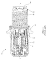
- the EMA 200 may, like the EMA 100, extend along an axis B-B', with B being located near a proximal portion of EMA 200 and B' being located near a distal portion of EMA 200.
- the EMA 200 may comprise an EMA housing 202.
- the EMA housing 202 may extend along axis B-B' and may house a variety of components, such as a ball nut piston 204 terminating in an end cap 205, a ball screw 206, a puck 208 coupled to end cap 205, and an ADU 210.
- the ADU 210 may be located with an ADU housing 211.
- the EMA housing 202 may comprise a generally annular structure configured to house the ball nut piston 204 and extending along the axis B-B'.
- the ball nut piston 204 may comprise a generally annular structure that extends axially along the axis B-B' within the EMA housing 202.
- the ball screw 206 may comprise a generally annular structure that extends axially along the axis B-B' within the ball nut piston 204.
- ADU housing 211 may comprise a generally annular structure that extends axially along the axis B-B' within ball nut piston 204 and partially within ball screw 206.
- ADU 210 may comprise a variety of drive components housed within and operably coupled to ADU housing 211, such as, for example, an electromechanical drive motor, drive shaft, gearing system, and the like.
- ADU 210 may be operably coupled to ball screw 206 and may drive ball screw 206 through a plurality of rotations.
- EMA 200 may operate in a manner similar to that described above with respect to EMA 100, with actuation of the electromechanical drive producing forward rotation of ball screw 206, and forward rotation of ball screw 206 producing translation of ball nut piston 204 in a distal linear direction.
- puck 208 coupled to ball nut piston 204 may also translate distally.
- Puck 208 may contact a brake stack 215 to apply a pressure force to the brake stack, thereby slowing and/or halting the rolling motion of the aircraft wheel.
- a back pressure force may be transferred back through puck 208, to ball nut piston 204, to the ball screw 206, and to the ADU housing 211 supporting ball screw 206 by virtue of the drivetrain of ADU 210.
- Reverse rotation of ball screw 206 may translate ball nut piston 204 in a proximal direction, retracting puck 208 away from the brake stack 215. Reverse rotation of ball screw 206 may be electromechanically driven by ADU 210 and/or the back pressure force from the brake stack.
- EMA 200 may also comprise a supplemental back drive mechanism disposed between the ball screw 206 and the ADU housing 211.
- a supplemental back drive mechanism may comprise a spring 220.
- Spring 220 may comprise a generally annular device located outside of ADU housing 211 and adjacent to a proximal end of ball screw 206.
- Spring 220 may be configured to fit within ball nut piston 204 when ball nut piston 204 is in a retracted position.
- Spring 220 may have a rotating end 223 and a stationary end 225. Rotating end 223 may be coupled, retained, installed, and/or otherwise captured in a structure of ball screw 206.
- stationary end 225 may be directly or indirectly coupled, retained, installed, and/or otherwise captured in a stationary body.
- a stationary body may be any structure of EMA 200 that does not rotate about axis B-B'.
- stationary end 225 may be directly coupled to a stationary body such as EMA housing 202 or ADU housing 211.
- stationary end 225 may be indirectly coupled to a stationary body such as EMA housing 202 or ADU housing 211 by means of an intermediate structure associated with the stationary body (i.e., by means of a serial connection), such as a clutch 230, described in greater detail below.
- spring 220 may be any suitable spring.
- spring 220 may be a wrap spring, a spiral spring, and/or a helical torsion spring.
- Spring 220 may be configured to store a back drive potential energy or torsional force suitable to provide back drive energy for EMA 200 and the associated brake drive system.
- spring 220 may be fabricated from round or square spring wire, machined from solid bar stock, or molded from plastic material. The material of spring 220 may be chosen to achieve corrosion resistance and sustain its properties at low as well as high ambient temperatures ranging from approximately -65 °F (-53 °C) to 350 °F (176 °C).
- spring 220 may be selected to provide various desired spring performance specifications such as a torsion coefficient and/or spring rate.
- spring 220 may comprise a torsion spring with a spring rate of 0.215 N-m/radian.
- a torsion spring may provide a torque build-up of 0.5 N-m with an angular deflection of 133 degrees.
- the energy stored by a torsion spring with these specifications may be suitable to provide 0.075 inches ( ⁇ 1.9 mm) of back drive or linear retraction of ball nut piston 204, which may be suitable to provide a desired running clearance position of EMA 200.
- a spring 220 may be configured to provide any suitable maximum angular deflection, spring rate, and torque capacity to thereby provide a back drive energy capacity matched to the characteristics of any particular EMA and/or brake system.
- spring 220 may be loaded with a torsional force or back drive potential energy.
- the back drive potential energy may be accumulated or stored by spring 220 in response to actuation of EMA 200 and forward rotation of ball screw 206, for example, during a braking operation.
- Forward rotation of ball screw 206 may produce rotation of rotating end 223 of spring 220, with rotation of the rotating end 223 producing an increased angular deflection of the spring and an accumulation of a back drive potential energy.
- spring 220 may be loaded by rotation of rotating end 223 in any suitable direction (e.g., clockwise or counter-clockwise) in response to forward rotation of ball screw 206.
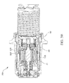
- the accumulated back drive potential energy in spring 220 may provide sufficient back drive energy (i.e., kinetic energy) to produce reverse rotation of ball screw 206 and retraction of ball nut piston 204, for example, to a running clearance position producing a running clearance position distance D between puck 208 and brake stack 215, when spring 220 is released.
- actuation of EMA 200 in a reverse direction electromechanically driven by ADU 210 may not be present to produce reverse rotation of ball screw 206 and retraction of ball nut piston 204 to a running clearance position or an intermediate clearance position, for example, in the event of a power loss to ADU 210.
- EMA 200 may not rely on back pressure from the brake stack to produce reverse rotation of ball screw 206 and retraction of ball nut piston 204.
- spring 220 may assist reverse electromechanically driven retraction of ball nut piston 204 to a running clearance position.
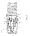
- an EMA may comprise a supplemental back drive mechanism coupled to a stationary body.
- EMA 300A may comprise spring 320A coupled to ADU housing 311. Rotating end 323A of spring 320A may be coupled to ball screw 306, while stationary end 325A of spring 320A may be attached directly to ADU housing 311.
- EMA 300B may comprise spring 320B coupled to EMA housing 302. Rotating end 323B of spring 320B may be coupled to ball screw 306, while stationary end 325B of spring 320B may be attached directly to EMA housing 302. In various embodiments, stationary end 325B may attach directly or indirectly to EMA housing 302.
- a supplemental back drive mechanism may comprise a clutch 230.
- stationary end of 225 of spring 220 may be coupled to a clutch 230.
- Clutch 230 may be located outside of and attached to a stationary body such as ADU housing 211 or EMA housing 202. Clutch 230 may further be located adjacent to a proximal end of spring 220 and attached to the stationary end 225 thereof. Similar to spring 220, clutch 230 may be configured to fit within ball nut piston 204 when ball nut piston 204 is in a retracted position.
- stationary end 225 of spring 220 may be indirectly coupled to a stationary body such as ADU housing 211 or EMA housing 202 by means of a serial connection to clutch 230 coupled to ADU housing 211 or EMA housing 202.
- clutch 230 may control release of the back drive potential energy that may be stored in spring 220.
- clutch 230 may be any suitable clutch, for example, a mechanical slip clutch or an electronic clutch.
- clutch 230 may control loading and/or release of spring 220.
- clutch 230 may prevent spring 220 from exceeding a torsion limit relative to the torque build up (i.e., the accumulation of back drive potential energy) and/or the angular deflection of the rotating end 223.
- clutch 230 may control loading of spring 220 by controlling rotation of stationary end 225, such as by variously locking or permitting rotation of stationary end 225 in response to various conditions of clutch 230 or another component of EMA 200.
- clutch 230 may remain unlocked and permit rotation of stationary end 225 and torsion spring 220 during actuation of EMA 200 in an initial braking period in which ball nut piston 204 and puck 208 advance from a running clearance position to a zero clearance position.
- a contact sensor in EMA 200 may signal a change of condition to clutch 230 when puck 208 reaches a zero clearance position, locking clutch 230 and stationary end 225 with respect to ADU housing 211, with further rotation of ball screw 206 subsequently loading spring 220 to provide back drive potential energy. Operation in this manner may provide for a decreased response time of EMA 200 during initial actuation of aircraft braking.
- clutch 230 may control release of back drive potential energy in response to a change of condition of clutch 230 or another component of EMA 200.
- clutch 230 may release back drive potential energy automatically in response to discontinuing actuation of forward electromechanical drive of ADU 210 during braking or in response to actuation of reverse electromechanical drive of ADU 210, in which case spring 220 may assist electromechanical back drive of ball nut piston 204 to a running clearance position.
- clutch 230 may release back drive potential in response to various other signals, such as a signal corresponding to a power loss by EMA 200, with spring 220 providing a failsafe mechanism for back drive of ball nut piston 204.
- a supplemental back drive mechanism of EMA 200 may provide various advantages over conventional EMA 100.
- the supplemental back drive provided by spring 220 may provide failsafe back drive operation in the event of a power failure to prevent unsafe operating conditions during a period of power loss to EMA 200.
- the supplemental back drive provided by spring 220 may also decrease the response time of electromechanically driven retraction of ball nut piston 204 to a running clearance position, thereby enhancing the performance of EMA 200 during normal powered operation.
- the supplemental back drive provided by spring 220 may also extend the operational life of EMA 200 by overcoming increasing mechanical inefficiency that may occur over the operational life of EMA 200.
- a new EMA may have an overall mechanical efficiency of 75%.
- the overall mechanical efficiency of an EMA may decrease over time as the drivetrain becomes worn, with a conventional EMA requiring replacement when the overall mechanical efficiency approaches, for example, 60% efficiency.
- An EMA 200 with supplemental back drive provided by spring 220 may lower the mechanical efficiency lower limit to, for example, 45% efficiency, thereby extending the operational lifespan of EMA 200.
- an EMA 200 with supplemental back drive provided by spring 220 may also be designed and manufactured using a lower efficiency drivetrain.
- an Acme screw may be substituted for a ball screw 206.
- EMA 200 may have a lower efficiency and may thereby decrease the complexity and costs of EMA 200 as compared to a conventional EMA 100 without a supplemental back drive.
- a method of supplying a back drive potential energy may comprise applying a forward drive to ball screw 206 in response to a first condition to produce a forward rotation of ball screw 206 (step 410).
- a first condition may comprise actuation of EMA 200 for braking of an aircraft.
- Forward rotation of ball screw 206 may produce a distal linear displacement of ball nut piston 208.
- Distal linear displacement of ball nut piston 204 may produce a decreased clearance position between puck 208 and brake stack 215, for example, to a zero clearance position ( FIG. 2A ).
- a method may further comprise increasing an angular deflection of torsion spring 220 in response to the forward rotation of ball screw 206 to produce a back drive potential energy (step 420).
- the back drive potential energy may be stored in torsion spring 220 (step 430) to supply back drive potential energy to EMA 200.
- a method may further comprise controlling releasing the back drive potential energy using clutch 230 (step 440).
- the back drive potential energy may be released in response to a second condition (step 450). Releasing the back drive potential energy may produce a reverse rotation of ball screw 206, which may be translated to a retraction of ball nut piston 204 and an increased clearance distance between puck 208 and brake stack 215, such as a running clearance position distance D ( FIG. 2B ) or an intermediate clearance position distance.
- reverse rotation of ball screw 206 and retraction of ball nut piston 204 may be produced without regard to actuation of a reverse electromechanical drive.
- references to "one embodiment”, “an embodiment”, “an example embodiment”, etc. indicate that the embodiment described may include a particular feature, structure, or characteristic, but every embodiment may not necessarily include the particular feature, structure, or characteristic. Moreover, such phrases are not necessarily referring to the same embodiment. Further, when a particular feature, structure, or characteristic is described in connection with an embodiment, it is submitted that it is within the knowledge of one skilled in the art to affect such feature, structure, or characteristic in connection with other embodiments whether or not explicitly described. After reading the description, it will be apparent to one skilled in the relevant art(s) how to implement the disclosure in alternative embodiments.
Landscapes
- Engineering & Computer Science (AREA)
- Mechanical Engineering (AREA)
- General Engineering & Computer Science (AREA)
- Transportation (AREA)
- Aviation & Aerospace Engineering (AREA)
- Braking Arrangements (AREA)
- Transmission Devices (AREA)
Applications Claiming Priority (1)
| Application Number | Priority Date | Filing Date | Title |
|---|---|---|---|
| US14/598,388 US9527584B2 (en) | 2015-01-16 | 2015-01-16 | Electromechanically actuated brake with supplemental back drive |
Publications (2)
| Publication Number | Publication Date |
|---|---|
| EP3045360A1 true EP3045360A1 (de) | 2016-07-20 |
| EP3045360B1 EP3045360B1 (de) | 2020-11-25 |
Family
ID=55168148
Family Applications (1)
| Application Number | Title | Priority Date | Filing Date |
|---|---|---|---|
| EP16151053.2A Active EP3045360B1 (de) | 2015-01-16 | 2016-01-13 | Elektromechanisch betätigte bremse mit zusätzlichem rückantrieb |
Country Status (2)
| Country | Link |
|---|---|
| US (1) | US9527584B2 (de) |
| EP (1) | EP3045360B1 (de) |
Families Citing this family (8)
| Publication number | Priority date | Publication date | Assignee | Title |
|---|---|---|---|---|
| US9933059B2 (en) * | 2015-07-06 | 2018-04-03 | Goodrich Corporation | Dual-rate linear actuator |
| US10830321B2 (en) * | 2016-02-19 | 2020-11-10 | Goodrich Corporation | Actuator ball screw for improved load sharing |
| DE102016216496A1 (de) * | 2016-09-01 | 2018-03-01 | Schaeffler Technologies AG & Co. KG | Gewindetrieb |
| US10106139B2 (en) | 2017-02-02 | 2018-10-23 | Goodrich Corporation | Brake systems and methods |
| JP6965802B2 (ja) * | 2018-03-20 | 2021-11-10 | トヨタ自動車株式会社 | 電動ブレーキアクチュエータ |
| JP7040287B2 (ja) * | 2018-05-25 | 2022-03-23 | トヨタ自動車株式会社 | 車両用ブレーキ装置 |
| US10927910B2 (en) | 2019-02-18 | 2021-02-23 | Akebono Brake Industry Co., Ltd | Brake system and control method thereof |
| CN110979642B (zh) * | 2019-11-01 | 2025-01-24 | 西安航空制动科技有限公司 | 电刹车装置的释放机构及其使用方法 |
Citations (3)
| Publication number | Priority date | Publication date | Assignee | Title |
|---|---|---|---|---|
| DE3724201A1 (de) * | 1987-07-22 | 1989-02-09 | Raco Elektro Maschinen Gmbh | Elektromotorische bremsbetaetigungsvorrichtung fuer schienenfahrzeuge |
| GB2290840A (en) * | 1994-06-01 | 1996-01-10 | Arthur Richard | Fail-safe brake actuation system |
| DE102007046953A1 (de) * | 2007-10-01 | 2009-04-02 | Lucas Automotive Gmbh | Kugelgewindetrieb für eine Kraftfahrzeugbremse und Kraftfahrzeugbremse |
Family Cites Families (5)
| Publication number | Priority date | Publication date | Assignee | Title |
|---|---|---|---|---|
| DE19652229A1 (de) * | 1996-12-16 | 1998-06-18 | Bosch Gmbh Robert | Elektromechanisch betätigbare Bremse |
| DE10014993A1 (de) * | 2000-03-25 | 2001-09-27 | Bosch Gmbh Robert | Elektromechanische Radbremsvorrichtung |
| JP4399754B2 (ja) * | 2000-05-31 | 2010-01-20 | 日立オートモティブシステムズ株式会社 | 電動ディスクブレーキ |
| US6679356B2 (en) * | 2002-01-23 | 2004-01-20 | Delphi Technologies, Inc. | Brake caliper backdrive apparatus and method |
| US7635050B2 (en) * | 2004-07-29 | 2009-12-22 | Ntn Corporation | Electric brake assembly |
-
2015
- 2015-01-16 US US14/598,388 patent/US9527584B2/en active Active
-
2016
- 2016-01-13 EP EP16151053.2A patent/EP3045360B1/de active Active
Patent Citations (3)
| Publication number | Priority date | Publication date | Assignee | Title |
|---|---|---|---|---|
| DE3724201A1 (de) * | 1987-07-22 | 1989-02-09 | Raco Elektro Maschinen Gmbh | Elektromotorische bremsbetaetigungsvorrichtung fuer schienenfahrzeuge |
| GB2290840A (en) * | 1994-06-01 | 1996-01-10 | Arthur Richard | Fail-safe brake actuation system |
| DE102007046953A1 (de) * | 2007-10-01 | 2009-04-02 | Lucas Automotive Gmbh | Kugelgewindetrieb für eine Kraftfahrzeugbremse und Kraftfahrzeugbremse |
Also Published As
| Publication number | Publication date |
|---|---|
| US20160207614A1 (en) | 2016-07-21 |
| US9527584B2 (en) | 2016-12-27 |
| EP3045360B1 (de) | 2020-11-25 |
Similar Documents
| Publication | Publication Date | Title |
|---|---|---|
| EP3045360B1 (de) | Elektromechanisch betätigte bremse mit zusätzlichem rückantrieb | |
| US6918470B2 (en) | Electromagnetic brake | |
| EP2250401B1 (de) | Stellglied | |
| CN103620255B (zh) | 具有选择性自锁的可机电致动的机动车制动器 | |
| CN109641583A (zh) | 用于车辆的盘式制动致动器 | |
| CN110307275B (zh) | 电动制动促动器 | |
| JP7040287B2 (ja) | 車両用ブレーキ装置 | |
| WO2011026826A1 (de) | Lineareinheit | |
| EP3907415A1 (de) | Bremsanordnung mit einem festen und einem schwimmenden bremssattelsystem und ein verfahren zur anwendung einer bremse | |
| EP2165899B1 (de) | Feststellbremsenmechanismus | |
| WO2010099325A2 (en) | Actuation system | |
| CN104641149A (zh) | 组合式车辆制动器 | |
| CN102770684A (zh) | 具有丝杠/螺母机构的车辆制动器 | |
| EP2353952A1 (de) | Steuerungssystem für einen Feststellbremsenmechanismus | |
| JP2013024389A (ja) | 車両用電動ブレーキ装置 | |
| CN107810343A (zh) | 电磁操作的制动钳的锁定设备、包括所述钳的制动钳、操作所述钳的方法 | |
| US8997946B2 (en) | Electric brake actuator module for aircraft | |
| CN104822956B (zh) | 线性单元以及用于制造线性单元的方法 | |
| US6840354B2 (en) | Brake actuator | |
| JP4898104B2 (ja) | 電気機械式制動装置用アクチュエータ | |
| JP4032386B2 (ja) | 電動ディスクブレーキ | |
| EP2965987A1 (de) | Bandparkbremse und verfahren | |
| US20230175564A1 (en) | Electric brake for vehicle | |
| US20080135349A1 (en) | Electric Brake for Aircraft | |
| EP2891829B1 (de) | Proximalpositionsstoppanordnung eines elektromechanischen Aktuators |
Legal Events
| Date | Code | Title | Description |
|---|---|---|---|
| PUAI | Public reference made under article 153(3) epc to a published international application that has entered the european phase |
Free format text: ORIGINAL CODE: 0009012 |
|
| AK | Designated contracting states |
Kind code of ref document: A1 Designated state(s): AL AT BE BG CH CY CZ DE DK EE ES FI FR GB GR HR HU IE IS IT LI LT LU LV MC MK MT NL NO PL PT RO RS SE SI SK SM TR |
|
| AX | Request for extension of the european patent |
Extension state: BA ME |
|
| STAA | Information on the status of an ep patent application or granted ep patent |
Free format text: STATUS: REQUEST FOR EXAMINATION WAS MADE |
|
| 17P | Request for examination filed |
Effective date: 20170118 |
|
| RBV | Designated contracting states (corrected) |
Designated state(s): AL AT BE BG CH CY CZ DE DK EE ES FI FR GB GR HR HU IE IS IT LI LT LU LV MC MK MT NL NO PL PT RO RS SE SI SK SM TR |
|
| GRAP | Despatch of communication of intention to grant a patent |
Free format text: ORIGINAL CODE: EPIDOSNIGR1 |
|
| STAA | Information on the status of an ep patent application or granted ep patent |
Free format text: STATUS: GRANT OF PATENT IS INTENDED |
|
| INTG | Intention to grant announced |
Effective date: 20200623 |
|
| GRAS | Grant fee paid |
Free format text: ORIGINAL CODE: EPIDOSNIGR3 |
|
| GRAA | (expected) grant |
Free format text: ORIGINAL CODE: 0009210 |
|
| STAA | Information on the status of an ep patent application or granted ep patent |
Free format text: STATUS: THE PATENT HAS BEEN GRANTED |
|
| AK | Designated contracting states |
Kind code of ref document: B1 Designated state(s): AL AT BE BG CH CY CZ DE DK EE ES FI FR GB GR HR HU IE IS IT LI LT LU LV MC MK MT NL NO PL PT RO RS SE SI SK SM TR |
|
| REG | Reference to a national code |
Ref country code: GB Ref legal event code: FG4D |
|
| REG | Reference to a national code |
Ref country code: CH Ref legal event code: EP |
|
| REG | Reference to a national code |
Ref country code: AT Ref legal event code: REF Ref document number: 1337941 Country of ref document: AT Kind code of ref document: T Effective date: 20201215 |
|
| REG | Reference to a national code |
Ref country code: DE Ref legal event code: R096 Ref document number: 602016048394 Country of ref document: DE |
|
| REG | Reference to a national code |
Ref country code: IE Ref legal event code: FG4D |
|
| REG | Reference to a national code |
Ref country code: AT Ref legal event code: MK05 Ref document number: 1337941 Country of ref document: AT Kind code of ref document: T Effective date: 20201125 |
|
| REG | Reference to a national code |
Ref country code: NL Ref legal event code: MP Effective date: 20201125 |
|
| PG25 | Lapsed in a contracting state [announced via postgrant information from national office to epo] |
Ref country code: FI Free format text: LAPSE BECAUSE OF FAILURE TO SUBMIT A TRANSLATION OF THE DESCRIPTION OR TO PAY THE FEE WITHIN THE PRESCRIBED TIME-LIMIT Effective date: 20201125 Ref country code: RS Free format text: LAPSE BECAUSE OF FAILURE TO SUBMIT A TRANSLATION OF THE DESCRIPTION OR TO PAY THE FEE WITHIN THE PRESCRIBED TIME-LIMIT Effective date: 20201125 Ref country code: PT Free format text: LAPSE BECAUSE OF FAILURE TO SUBMIT A TRANSLATION OF THE DESCRIPTION OR TO PAY THE FEE WITHIN THE PRESCRIBED TIME-LIMIT Effective date: 20210325 Ref country code: NO Free format text: LAPSE BECAUSE OF FAILURE TO SUBMIT A TRANSLATION OF THE DESCRIPTION OR TO PAY THE FEE WITHIN THE PRESCRIBED TIME-LIMIT Effective date: 20210225 Ref country code: GR Free format text: LAPSE BECAUSE OF FAILURE TO SUBMIT A TRANSLATION OF THE DESCRIPTION OR TO PAY THE FEE WITHIN THE PRESCRIBED TIME-LIMIT Effective date: 20210226 |
|
| PG25 | Lapsed in a contracting state [announced via postgrant information from national office to epo] |
Ref country code: AT Free format text: LAPSE BECAUSE OF FAILURE TO SUBMIT A TRANSLATION OF THE DESCRIPTION OR TO PAY THE FEE WITHIN THE PRESCRIBED TIME-LIMIT Effective date: 20201125 Ref country code: BG Free format text: LAPSE BECAUSE OF FAILURE TO SUBMIT A TRANSLATION OF THE DESCRIPTION OR TO PAY THE FEE WITHIN THE PRESCRIBED TIME-LIMIT Effective date: 20210225 Ref country code: PL Free format text: LAPSE BECAUSE OF FAILURE TO SUBMIT A TRANSLATION OF THE DESCRIPTION OR TO PAY THE FEE WITHIN THE PRESCRIBED TIME-LIMIT Effective date: 20201125 Ref country code: SE Free format text: LAPSE BECAUSE OF FAILURE TO SUBMIT A TRANSLATION OF THE DESCRIPTION OR TO PAY THE FEE WITHIN THE PRESCRIBED TIME-LIMIT Effective date: 20201125 Ref country code: IS Free format text: LAPSE BECAUSE OF FAILURE TO SUBMIT A TRANSLATION OF THE DESCRIPTION OR TO PAY THE FEE WITHIN THE PRESCRIBED TIME-LIMIT Effective date: 20210325 Ref country code: LV Free format text: LAPSE BECAUSE OF FAILURE TO SUBMIT A TRANSLATION OF THE DESCRIPTION OR TO PAY THE FEE WITHIN THE PRESCRIBED TIME-LIMIT Effective date: 20201125 |
|
| REG | Reference to a national code |
Ref country code: LT Ref legal event code: MG9D |
|
| PG25 | Lapsed in a contracting state [announced via postgrant information from national office to epo] |
Ref country code: HR Free format text: LAPSE BECAUSE OF FAILURE TO SUBMIT A TRANSLATION OF THE DESCRIPTION OR TO PAY THE FEE WITHIN THE PRESCRIBED TIME-LIMIT Effective date: 20201125 |
|
| PG25 | Lapsed in a contracting state [announced via postgrant information from national office to epo] |
Ref country code: SK Free format text: LAPSE BECAUSE OF FAILURE TO SUBMIT A TRANSLATION OF THE DESCRIPTION OR TO PAY THE FEE WITHIN THE PRESCRIBED TIME-LIMIT Effective date: 20201125 Ref country code: RO Free format text: LAPSE BECAUSE OF FAILURE TO SUBMIT A TRANSLATION OF THE DESCRIPTION OR TO PAY THE FEE WITHIN THE PRESCRIBED TIME-LIMIT Effective date: 20201125 Ref country code: EE Free format text: LAPSE BECAUSE OF FAILURE TO SUBMIT A TRANSLATION OF THE DESCRIPTION OR TO PAY THE FEE WITHIN THE PRESCRIBED TIME-LIMIT Effective date: 20201125 Ref country code: CZ Free format text: LAPSE BECAUSE OF FAILURE TO SUBMIT A TRANSLATION OF THE DESCRIPTION OR TO PAY THE FEE WITHIN THE PRESCRIBED TIME-LIMIT Effective date: 20201125 Ref country code: SM Free format text: LAPSE BECAUSE OF FAILURE TO SUBMIT A TRANSLATION OF THE DESCRIPTION OR TO PAY THE FEE WITHIN THE PRESCRIBED TIME-LIMIT Effective date: 20201125 Ref country code: LT Free format text: LAPSE BECAUSE OF FAILURE TO SUBMIT A TRANSLATION OF THE DESCRIPTION OR TO PAY THE FEE WITHIN THE PRESCRIBED TIME-LIMIT Effective date: 20201125 |
|
| REG | Reference to a national code |
Ref country code: DE Ref legal event code: R119 Ref document number: 602016048394 Country of ref document: DE |
|
| PG25 | Lapsed in a contracting state [announced via postgrant information from national office to epo] |
Ref country code: DK Free format text: LAPSE BECAUSE OF FAILURE TO SUBMIT A TRANSLATION OF THE DESCRIPTION OR TO PAY THE FEE WITHIN THE PRESCRIBED TIME-LIMIT Effective date: 20201125 Ref country code: MC Free format text: LAPSE BECAUSE OF FAILURE TO SUBMIT A TRANSLATION OF THE DESCRIPTION OR TO PAY THE FEE WITHIN THE PRESCRIBED TIME-LIMIT Effective date: 20201125 |
|
| REG | Reference to a national code |
Ref country code: CH Ref legal event code: PL |
|
| PG25 | Lapsed in a contracting state [announced via postgrant information from national office to epo] |
Ref country code: LU Free format text: LAPSE BECAUSE OF NON-PAYMENT OF DUE FEES Effective date: 20210113 |
|
| PLBE | No opposition filed within time limit |
Free format text: ORIGINAL CODE: 0009261 |
|
| STAA | Information on the status of an ep patent application or granted ep patent |
Free format text: STATUS: NO OPPOSITION FILED WITHIN TIME LIMIT |
|
| REG | Reference to a national code |
Ref country code: BE Ref legal event code: MM Effective date: 20210131 |
|
| PG25 | Lapsed in a contracting state [announced via postgrant information from national office to epo] |
Ref country code: IT Free format text: LAPSE BECAUSE OF FAILURE TO SUBMIT A TRANSLATION OF THE DESCRIPTION OR TO PAY THE FEE WITHIN THE PRESCRIBED TIME-LIMIT Effective date: 20201125 Ref country code: AL Free format text: LAPSE BECAUSE OF FAILURE TO SUBMIT A TRANSLATION OF THE DESCRIPTION OR TO PAY THE FEE WITHIN THE PRESCRIBED TIME-LIMIT Effective date: 20201125 Ref country code: NL Free format text: LAPSE BECAUSE OF FAILURE TO SUBMIT A TRANSLATION OF THE DESCRIPTION OR TO PAY THE FEE WITHIN THE PRESCRIBED TIME-LIMIT Effective date: 20201125 |
|
| 26N | No opposition filed |
Effective date: 20210826 |
|
| PG25 | Lapsed in a contracting state [announced via postgrant information from national office to epo] |
Ref country code: ES Free format text: LAPSE BECAUSE OF FAILURE TO SUBMIT A TRANSLATION OF THE DESCRIPTION OR TO PAY THE FEE WITHIN THE PRESCRIBED TIME-LIMIT Effective date: 20201125 Ref country code: DE Free format text: LAPSE BECAUSE OF NON-PAYMENT OF DUE FEES Effective date: 20210803 Ref country code: SI Free format text: LAPSE BECAUSE OF FAILURE TO SUBMIT A TRANSLATION OF THE DESCRIPTION OR TO PAY THE FEE WITHIN THE PRESCRIBED TIME-LIMIT Effective date: 20201125 Ref country code: LI Free format text: LAPSE BECAUSE OF NON-PAYMENT OF DUE FEES Effective date: 20210131 Ref country code: CH Free format text: LAPSE BECAUSE OF NON-PAYMENT OF DUE FEES Effective date: 20210131 |
|
| PG25 | Lapsed in a contracting state [announced via postgrant information from national office to epo] |
Ref country code: IE Free format text: LAPSE BECAUSE OF NON-PAYMENT OF DUE FEES Effective date: 20210113 |
|
| PG25 | Lapsed in a contracting state [announced via postgrant information from national office to epo] |
Ref country code: IS Free format text: LAPSE BECAUSE OF FAILURE TO SUBMIT A TRANSLATION OF THE DESCRIPTION OR TO PAY THE FEE WITHIN THE PRESCRIBED TIME-LIMIT Effective date: 20210325 |
|
| PG25 | Lapsed in a contracting state [announced via postgrant information from national office to epo] |
Ref country code: BE Free format text: LAPSE BECAUSE OF NON-PAYMENT OF DUE FEES Effective date: 20210131 |
|
| PG25 | Lapsed in a contracting state [announced via postgrant information from national office to epo] |
Ref country code: HU Free format text: LAPSE BECAUSE OF FAILURE TO SUBMIT A TRANSLATION OF THE DESCRIPTION OR TO PAY THE FEE WITHIN THE PRESCRIBED TIME-LIMIT; INVALID AB INITIO Effective date: 20160113 |
|
| P01 | Opt-out of the competence of the unified patent court (upc) registered |
Effective date: 20230522 |
|
| PG25 | Lapsed in a contracting state [announced via postgrant information from national office to epo] |
Ref country code: CY Free format text: LAPSE BECAUSE OF FAILURE TO SUBMIT A TRANSLATION OF THE DESCRIPTION OR TO PAY THE FEE WITHIN THE PRESCRIBED TIME-LIMIT Effective date: 20201125 |
|
| PG25 | Lapsed in a contracting state [announced via postgrant information from national office to epo] |
Ref country code: MK Free format text: LAPSE BECAUSE OF FAILURE TO SUBMIT A TRANSLATION OF THE DESCRIPTION OR TO PAY THE FEE WITHIN THE PRESCRIBED TIME-LIMIT Effective date: 20201125 |
|
| PG25 | Lapsed in a contracting state [announced via postgrant information from national office to epo] |
Ref country code: MT Free format text: LAPSE BECAUSE OF FAILURE TO SUBMIT A TRANSLATION OF THE DESCRIPTION OR TO PAY THE FEE WITHIN THE PRESCRIBED TIME-LIMIT Effective date: 20201125 |
|
| PG25 | Lapsed in a contracting state [announced via postgrant information from national office to epo] |
Ref country code: TR Free format text: LAPSE BECAUSE OF FAILURE TO SUBMIT A TRANSLATION OF THE DESCRIPTION OR TO PAY THE FEE WITHIN THE PRESCRIBED TIME-LIMIT Effective date: 20201125 |
|
| PGFP | Annual fee paid to national office [announced via postgrant information from national office to epo] |
Ref country code: GB Payment date: 20251220 Year of fee payment: 11 |
|
| PGFP | Annual fee paid to national office [announced via postgrant information from national office to epo] |
Ref country code: FR Payment date: 20251218 Year of fee payment: 11 |