EP3045328B2 - Anhängekupplung - Google Patents
Anhängekupplung Download PDFInfo
- Publication number
- EP3045328B2 EP3045328B2 EP16151064.9A EP16151064A EP3045328B2 EP 3045328 B2 EP3045328 B2 EP 3045328B2 EP 16151064 A EP16151064 A EP 16151064A EP 3045328 B2 EP3045328 B2 EP 3045328B2
- Authority
- EP
- European Patent Office
- Prior art keywords
- cross member
- flange
- trailer coupling
- elements
- coupling according
- Prior art date
- Legal status (The legal status is an assumption and is not a legal conclusion. Google has not performed a legal analysis and makes no representation as to the accuracy of the status listed.)
- Active
Links
Images


Classifications
-
- B—PERFORMING OPERATIONS; TRANSPORTING
- B60—VEHICLES IN GENERAL
- B60D—VEHICLE CONNECTIONS
- B60D1/00—Traction couplings; Hitches; Draw-gear; Towing devices
- B60D1/48—Traction couplings; Hitches; Draw-gear; Towing devices characterised by the mounting
- B60D1/56—Traction couplings; Hitches; Draw-gear; Towing devices characterised by the mounting securing to the vehicle bumper
-
- B—PERFORMING OPERATIONS; TRANSPORTING
- B60—VEHICLES IN GENERAL
- B60D—VEHICLE CONNECTIONS
- B60D1/00—Traction couplings; Hitches; Draw-gear; Towing devices
- B60D1/01—Traction couplings or hitches characterised by their type
- B60D1/06—Ball-and-socket hitches
-
- B—PERFORMING OPERATIONS; TRANSPORTING
- B60—VEHICLES IN GENERAL
- B60D—VEHICLE CONNECTIONS
- B60D1/00—Traction couplings; Hitches; Draw-gear; Towing devices
- B60D1/48—Traction couplings; Hitches; Draw-gear; Towing devices characterised by the mounting
- B60D1/485—Traction couplings; Hitches; Draw-gear; Towing devices characterised by the mounting mounted by means of transversal members attached to the frame of a vehicle
-
- B—PERFORMING OPERATIONS; TRANSPORTING
- B60—VEHICLES IN GENERAL
- B60D—VEHICLE CONNECTIONS
- B60D1/00—Traction couplings; Hitches; Draw-gear; Towing devices
- B60D1/48—Traction couplings; Hitches; Draw-gear; Towing devices characterised by the mounting
- B60D1/54—Traction couplings; Hitches; Draw-gear; Towing devices characterised by the mounting collapsible or retractable when not in use, e.g. hide-away hitches
Definitions
- the invention relates to a trailer hitch for motor vehicles, comprising a cross member that can be connected to a motor vehicle body and a bearing unit that carries a ball neck that is connected to the bearing unit at a first end and carries a coupling ball at a second end, and a bearing unit that carries and has The holding base connected to the crossbeam, wherein the holding base has a flange unit for receiving the bearing unit and two holding elements which start from the flange unit and run at a distance from one another and engage on the crossbeam.
- hitches are from the prior art, for example EP 2 006 192 known.
- the support base is formed by two elements made of flat material, each of which comprises a flange element that contributes to the formation of the flange unit and each of which forms one of the support elements that extend from the flange unit extending starting in the direction of the cross member.
- the flange elements could, for example, be arranged separately by spacer elements to form the flange unit.
- the flange unit is formed from the flange elements in such a way that the flange elements bear against one another with contact sides facing one another.
- each of the retaining elements is firmly connected to the respective flange element, the stable connection between the cross member and the respective flange element is established.
- the holding elements could be connected to the respective flange element by positive locking or joining.
- a particularly advantageous solution provides that each of the holding elements merges into the respective flange element in one piece, so that each holding element with the associated flange element can be produced particularly easily and thus inexpensively.
- Each of the holding elements is preferably arranged relative to the corresponding flange element in such a way that it merges into the respective flange element via a bending region.
- a particularly favorable solution provides for the holding elements to run at an increasing distance from one another as the distance from the flange unit increases.
- a preferred solution provides that the respective holding elements extend at an increasing distance from a central plane of the flange unit as they extend away from the flange unit.
- the central plane of the flange unit is preferably defined in that this is the geometric plane which runs between the flange elements in the flange unit, for example abutting one another.
- the solution according to the invention provides that the holding elements are bent over relative to the corresponding flange elements along a bending line, so that the holding elements extend relative to the central plane in which the holding elements, starting from the bending line with increasing extension away from the bending line, also in increasing distance from the median plane.
- both the flange element and the holding element are formed from a flat piece of flat material and thus run at an angle to one another.
- the holding elements run at an acute angle to a center plane of the flange unit.
- the holding element and the respective flange element of the respective element enclose an obtuse angle with one another.
- the obtuse angle between the holding element and the respective flange element is in the range between 100 degrees and 170 degrees and is preferably in the range between 120 degrees and 160 degrees.
- the invention provides that the projection of the bending lines of the elements onto the central plane results in an intersecting course of the projected bending lines, ie the bending lines projected onto the central plane run transversely to one another.
- the projected bending lines enclose an acute angle with one another, which is, for example, in the range between 15 degrees and 140 degrees and preferably in the range between 40 degrees and 100 degrees.
- the holding base resulting from the two elements with the flange elements and the holding elements is particularly resistant to bending and torsion, since one of the elements counteracts a flexible behavior of the other element.
- a stable connection between the retaining elements and the cross member can be achieved in particular when the retaining elements are in contact with an outer peripheral surface of the cross member.
- the holding elements are provided with cross member mounts that bear against the outer peripheral surface of the cross member.
- the cross member mounts are preferably designed as cutouts provided in the holding elements, so that the holding elements in the region of the cross member mounts extend transversely to the cross member, in particular at an angle deviating from 90°.
- the cross member receptacles are formed by edge contours of the retaining elements that delimit the cutouts and rest on the outer peripheral surface of the cross member.
- the cross member mounts could theoretically bear against the outer peripheral surface of the cross member in individual sections.
- cross member mounts lie against the outer peripheral surface along their edge contours.
- the cross member mounts encompass the outer peripheral surface of the cross member over an angular range of at least 120° relative to a central axis of the cross member.
- cross member mounts are preferably welded in a line to the cross member along their edge contour.
- a particularly stable embodiment of the holding base provides that the cross member mounts are arranged on the holding elements in areas with the greatest distance from one another.
- the motor vehicle designated as a whole with 10 comprises a vehicle body 12 on which a trailer hitch 20 according to the invention is mounted in a rear area 14, which has a cross member 22 covered by a bumper unit 16 and extending transversely to a longitudinal direction 18 of the vehicle body 12 and transversely over the rear area 14 and has side supports 24 which extend approximately parallel to the longitudinal direction 18 of the vehicle body 12 along body wall sections 26 and are fixed to them, which, together with the cross member 22, form a holding unit 28 which is partly covered by the vehicle body 12 and partly by the bumper unit 16 .
- the swivel bearing unit 30 makes it possible to move the ball neck 40 from one in 2 and 3 illustrated working position A, in which a ball center axis 48 of the coupling ball 46 is in a vertical vehicle longitudinal center plane FL parallel to the longitudinal direction 18, about a transverse, in particular oblique, preferably at an acute angle, to the vehicle longitudinal center plane FL pivot axis 50 into an in 3 illustrated rest position R, in which a central section 52 of the ball neck extends transversely to the longitudinal center plane FL of the vehicle and the coupling ball 46 lies to the side of the vehicle's longitudinal center plane FL, as in FIG 3 shown.
- the ball neck 40 is arranged in the rest position R in a position covered by the bumper unit 16 of the vehicle body 12 to the side of the longitudinal center plane FL of the vehicle.
- the support base 32 comprises a flange unit 62, on which the pivot bearing unit 30 is mounted, and starting from the flange unit 62 extending support members 64 and 66, as in Figs Figures 3 to 11 shown, starting from the flange unit 62 increasingly extend away from each other and in particular starting from a geometric center plane 68 of the flange unit 62 with increasing distance from the flange unit 62 at increasing distance from the center plane 68, as in the 6 and 9 shown.
- the geometric center plane 68 as in 6 shown, obliquely to a central axis 128 of the cross member 22 in the area of the cross member 22 that carries the holding base 32.
- the holding base 32 is formed by two elements 74 and 76 made of flat material, which have two flange elements 84 and 86 which, for example, abut one another with contact sides 94 and 96 facing one another, with the contact sides 94 and 96 each contacting the central plane 68 of the flange unit 62 adjoin, so that both contact sides 94 and 96 are ultimately arranged adjacent to the geometric center plane 68.
- the element 74 comprises the holding element 64, which is bent relative to the flange element 84 along a bending line 104 and thus, starting from the bending line 104, at an angle to the central plane 68 and with increasing distance from the bending line 104 with increasing distance from the center plane 68 runs.
- the holding element 64 is preferably also a part of the flat material from which the element 74 is formed, so that—as in FIG Figures 8 to 11 shown - the flange element 84 and the holding element 64 are each flat material parts which merge into one another in one piece via a bending region 102 predetermined by the bending line 104, the flat material parts enclosing an obtuse angle ⁇ with one another which is in the range from 100 degrees to 170 degrees.
- the acute angle ⁇ at which the holding element 64 runs relative to the contact side 94 and thus to the central plane 68 is in the range from 10 degrees to 80 degrees, preferably in the range from 20 degrees to 60 degrees.
- the holding element 66 is also - as in 8 and 9 shown - portion of member 76 including flange member 86 relative to which retaining member 66 is angled from a bend line 106 .
- the element 76 is also formed from flat material, with the flange element 86 and the holding element 66 merging into one another via a bending region 108 predetermined by the bending line 106 and the flat material parts enclose an obtuse angle with one another, which is also in the range from 100 degrees to 170 degrees.
- the holding element 66 extends relative to the contact side 96 of the flange element 66 starting from the bending line 106 at an angle which is in the range from 10 degrees to 80 degrees, preferably in the range from 20 degrees to 60 degrees.
- the holding element 66 also extends, starting from the bending line 106, at an acute angle relative to the center plane 68.
- the bending lines 104 and 106 do not run parallel to one another, but rather their projection onto the central plane 68, which in 6 represents the plane of the drawing, results in an acute angle ⁇ between the bend lines 104 and 106, which is in the range between 15 degrees and 140 degrees, preferably in the range between 40 degrees and 100 degrees.
- the flange elements 84 and 86 are in turn provided with identically arranged openings 112, which are arranged around the pivot axis 50, preferably on a circular line around the pivot axis 50, and are used to accommodate mounting screws with which the pivot bearing unit 30 can be mounted on the flange unit 62 .
- flange elements 84 and 86 for example by spot welding or by gluing areal to connect to each other.
- the holding elements 64, 66 are provided with cross member mounts 114, 116 ( Figures 7 to 9 ), which are produced by cutouts from the flat material forming the holding elements 64, 66, the course of edge contours 124, 126 of the crossmember mounts 114 and 116 formed by the cutouts being adapted to an outer peripheral surface 118 of the crossmember 22, on which the crossmember mounts 114 and 116 preferably lie in linear contact with their edge contours 124 and 126, and are welded to the cross member 22 along the linearly adjacent edge contours 124 and 126, with a linear welded connection preferably being produced.
- the cross member mounts 114 and 116 are preferably designed in such a way that, as in 6 and 7 shown, include the outer circumferential surface 118 of the cross member 22 in a circumferential area which extends over an angular range of more than 120 degrees about a central axis of the cross member, preferably an angular range of more than 150 degrees about the central axis 128 of the cross member 22.
- the holding base 32 allows a stable and, in particular, rigid connection between the holding base 32 and the cross member 22 due to the holding elements 64 and 66, which are spread apart from one another, and is also easy to produce in that it comprises two elements 74 and 76 made of a plate-shaped flat material, in which the retaining element 64, 66 is bent relative to the flange element 84 and 86 forming the flange unit 62 along a bending line 104, 106 in order to, on the one hand, with flange elements 84 and 86 which are connected to one another and abutting to form the flange unit 62, on the one hand, prevent the spreading course of the retaining elements 84 and 86 to obtain.
- the support base 32' comprises a flange unit 62', which is formed from more than two, for example four, elements 74', 75', 76' and 77' made of flat material, each of the elements 74' to 77' has a holding element 64', 65', 66' and 67' and a corresponding flange element 84', 85', 86', 87'.
- All flange elements 84′, 85′, 86′, 87′ run parallel to the central plane 68′ and in particular lie flat against one another in order to form the flange unit 62′, which carries the bearing unit 30.
- the holding elements 64', 65', 66' and 67' enclose an obtuse angle with the flange elements 84', 85', 86', 87'.
- the retaining members 64', 65', 66', 67' are spaced increasingly apart from each other as the distance from the flange unit 62' increases.
Landscapes
- Engineering & Computer Science (AREA)
- Transportation (AREA)
- Mechanical Engineering (AREA)
- Rolling Contact Bearings (AREA)
- Connection Of Plates (AREA)
- Vehicle Body Suspensions (AREA)
- Body Structure For Vehicles (AREA)
- Clamps And Clips (AREA)
Description
- Die Erfindung betrifft eine Anhängekupplung für Kraftfahrzeuge, umfassend einen mit einer Kraftfahrzeugkarosserie verbindbaren Querträger und eine Lagereinheit, welche einen Kugelhals trägt, der an einem ersten Ende mit der Lagereinheit verbunden ist und an einem zweiten Ende eine Kupplungskugel trägt, und eine die Lagereinheit tragende und mit dem Querträger verbundene Haltebasis, wobei die Haltebasis eine Flanscheinheit zur Aufnahme der Lagereinheit sowie zwei sich von der Flanscheinheit ausgehende und dabei im Abstand zueinander verlaufende Halteelemente aufweist, die an dem Querträger angreifen.
- Derartige Anhängekupplungen sind aus dem Stand der Technik, beispielsweise der
EP 2 006 192 bekannt. - Bei diesen Anhängekupplungen besteht das Problem, dass die Haltebasis möglichst stabil und kostengünstig herzustellen sein soll.
- Diese Aufgabe wird bei einer Anhängekupplung der eingangs beschriebenen Art erfindungsgemäß durch die Merkmale des Anspruchs 1. gelöst,
Der Vorteil der erfindungsgemäßen Lösung ist darin zu sehen, dass durch die ausgehend von der Flanscheinheit sich im Abstand zueinander verlaufenden und an dem Querträger angreifenden Halteelemente eine stabile und insbesondere biegesteife sowie kostengünstige Verbindung zwischen der Lagereinheit und Querträger möglich ist. - Prinzipiell wäre es denkbar, die Haltebasis aus der Flanscheinheit und den Halteelementen zusammenzusetzen.
- Hinsichtlich der Herstellung der erfindungsgemäßen Lösung ist es besonders vorteilhaft, dass die Haltebasis durch zwei Elemente aus Flachmaterial gebildet ist, von denen jedes ein Flanschelement umfasst, welches zur Bildung der Flanscheinheit beiträgt, und von denen jede eines der Halteelemente bildet, die sich von der Flanscheinheit ausgehend in Richtung des Querträgers erstrecken.
- Die Flanschelemente könnten beispielsweise zur Ausbildung der Flanscheinheit durch Abstandselemente getrennt angeordnet sein.
- Besonders günstig ist es dabei, wenn die Flanscheinheit aus den Flanschelementen derart gebildet ist, dass die Flanschelemente mit einander zugewandten Anlageseiten aneinander anliegen.
- Eine derartige Lösung hat den Vorteil, dass dadurch aufgrund des Aufbaus der Flanscheinheit aus zwei Flanschelementen in einfacher Weise eine stabile Flanscheinheit herstellbar ist.
- Dadurch, dass jedes der Halteelemente fest mit dem jeweiligen Flanschelement verbunden ist, ist die stabile Verbindung zwischen dem Querträger und dem jeweiligen Flanschelement hergestellt.
- Dabei könnten die Halteelemente durch Formschluss oder Fügen mit dem jeweiligen Flanschelement verbunden sein.
- Eine besonders vorteilhafte Lösung sieht vor, dass jedes der Halteelemente einstückig in das jeweilige Flanschelement übergeht, so dass dadurch jedes Halteelement mit dem dazugehörigen Flanschelement besonders einfach und somit kostengünstig herstellbar ist.
- Vorzugsweise ist jedes der Halteelemente relativ zum entsprechenden Flanschelement so angeordnet, dass es über einen Biegebereich in das jeweilige Flanschelement übergeht.
- Hinsichtlich der Ausrichtung der Halteelemente relativ zueinander wurden bislang noch keine Angaben gemacht.
- So sieht eine besonders günstige Lösung vor, dass die Halteelemente mit zunehmendem Abstand von der Flanscheinheit in zunehmendem Abstand voneinander verlaufen.
- Eine bevorzugte Lösung sieht vor, dass die jeweiligen Halteelemente sich mit zunehmender Erstreckung von der Flanscheinheit weg in zunehmendem Abstand von einer Mittelebene der Flanscheinheit erstrecken.
- Vorzugsweise ist die Mittelebene der Flanscheinheit dadurch definiert, dass diese die geometrische Ebene ist, die zwischen den, beispielsweise aneinander anliegenden, Flanschelementen in der Flanscheinheit verläuft.
- Die erfindungsgemäße Lösung sieht vor, dass die Halteelemente relativ zu den entsprechenden Flanschelementen längs einer Biegelinie umgebogen sind, so dass damit ein Verlauf der Halteelemente relativ zur Mittelebene entsteht, bei welchem sich die Halteelemente ausgehend von der Biegelinie mit zunehmender Erstreckung von der Biegelinie weg auch in zunehmendem Abstand von der Mittelebene erstrecken.
- Im einfachsten Fall sind sowohl das Flanschelement als auch das Halteelement aus einem ebenen Stück Flachmaterial gebildet und verlaufen dadurch in einem Winkel zueinander.
- Dabei verlaufen in einem besonders einfachen Fall die Halteelemente in einem spitzen Winkel zu einer Mittelebene der Flanscheinheit.
- Bei der erfindungsgemäßen Lösung schließen das Halteelement und das jeweilige Flanschelement des jeweiligen Elements einen stumpfen Winkel miteinander ein.
- Beispielsweise ist hierbei vorgesehen, dass der stumpfe Winkel zwischen dem Halteelement und dem jeweiligen Flanschelement im Bereich zwischen 100 Grad und 170 Grad liegt und vorzugsweise im Bereich zwischen 120 Grad und 160 Grad liegt.
- Um eine möglichst optimale Stabilität zu erhalten ist erfindungsgemäß vorgesehen, dass die Projektion der Biegelinien der Elemente auf die Mittelebene einen sich schneidenden Verlauf der projizierten Biegelinien ergibt, das heißt, dass die auf die Mittelebene projizierten Biegelinien quer zueinander verlaufen.
- Insbesondere ist dabei vorgesehen, dass die projizierten Biegelinien einen spitzen Winkel miteinander einschließen, der beispielsweise im Bereich zwischen 15 Grad und 140 Grad liegt und vorzugsweise im Bereich zwischen 40 Grad und 100 Grad liegt.
- Dadurch, dass die projizierten Biegelinien in der Mittelebene quer zueinander verlaufen, ist die sich aus den beiden Elementen mit den Flanschelementen und den Halteelementen ergebende Haltebasis besonders biege- und verwindungssteif, da jeweils das eine der Elemente einem biegeelastischen Verhalten des anderen der Elemente entgegenwirkt.
- Hinsichtlich der Verbindung zwischen den Halteelementen und dem Querträger wurden bislang keine näheren Angaben gemacht.
- Prinzipiell wäre es denkbar, die Halteelemente beispielsweise mit dem Querträger zu verschrauben oder zu verkleben.
- Eine besonders günstige Lösung sieht jedoch vor, dass die Halteelemente mit dem Querträger verschweißt sind.
- Eine stabile Verbindung zwischen den Halteelementen und dem Querträger ist insbesondere dann erreichbar, wenn die Halteelemente an einer Außenumfangsfläche des Querträgers anliegen.
- Insbesondere sind dabei die Halteelemente mit Querträgeraufnahmen versehen, die an der Außenumfangsfläche des Querträgers anliegen.
- Die Querträgeraufnahmen sind vorzugsweise als in den Halteelementen vorgesehene Ausschnitte ausgeführt, so dass sich die Halteelemente im Bereich der Querträgeraufnahmen quer zu dem Querträger, insbesondere in einem von 90° abweichenden Winkel, erstrecken.
- Insbesondere sind die Querträgeraufnahmen durch die Ausschnitte begrenzende Randkonturen der Halteelemente gebildet, welche an der Außenumfangsfläche des Querträgers anliegen.
- Dabei könnten theoretisch die Querträgeraufnahmen in einzelnen Abschnitten an der Außenumfangsfläche des Querträgers anliegen.
- Eine besonders vorteilhafte Lösung sieht jedoch vor, dass die Querträgeraufnahmen längs ihrer Randkonturen an der Außenumfangsfläche anliegen.
- Um dabei eine stabile Verbindung zum Querträger zu schaffen, ist vorzugsweise vorgesehen, dass die Querträgeraufnahmen die Außenumfangsfläche des Querträgers über einen Winkelbereich von mindestens 120° bezogen auf eine Mittelachse des Querträgers umfassen.
- Vorzugsweise ist vorgesehen, dass die Querträgeraufnahmen die Außenumfangsfläche des Querträgers über einen Winkel von mindestens 150 Grad, noch besser von mindestens 180 Grad, umfassen.
- Ferner sind vorzugsweise die Querträgeraufnahmen längs ihrer Randkontur linienförmig mit dem Querträger verschweißt.
- Eine besonders stabile Ausführungsform der Haltebasis sieht vor, dass die Querträgeraufnahmen an den Halteelementen in Bereichen mit dem größten Abstand voneinander angeordnet sind.
- Weitere Merkmale und Vorteile der Erfindung sind Gegenstand der nachfolgenden Beschreibung sowie der zeichnerischen Darstellung eines Ausführungsbeispiels.
- In der Zeichnung zeigen:
- Fig. 1
- eine perspektivische teilweise aufgebrochene Ansicht eines Kraftfahrzeugs mit einer erfindungsgemäßen Anhängekupplung;
- Fig. 2
- eine perspektivische Darstellung eines ersten Ausführungsbeispiels der erfindungsgemäßen Anhängekupplung;
- Fig. 3
- eine Ansicht der Anhängekupplung in Richtung des Pfeils A in
Fig. 2 ; - Fig. 4
- eine Ansicht in Richtung des Pfeils B in
Fig. 2 ; - Fig. 5
- eine Ansicht in Richtung eines Pfeils C in
Fig. 2 und in der Arbeitsstellung; - Fig. 6
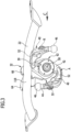
- eine Ansicht eines Querträgers mit einer Haltebasis in Richtung des Pfeils D in
Fig. 2 ; - Fig. 7
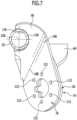
- einen Schnitt längs Linie 7-7 in
Fig. 6 ; - Fig. 8
- eine vergrößerte Ansicht der Haltebasis in Richtung des Pfeils E in
Fig. 6 ; - Fig. 9
- eine vergrößerte Ansicht der Haltebasis in Richtung des Pfeils F in
Fig. 8 ; - Fig. 10
- eine Ansicht der Haltebasis in Richtung des Pfeils G in
Fig. 9 ; - Fig. 11
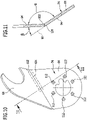
- einen Schnitt längs Linie 11-11 in
Fig. 10 und - Fig. 12
- eine Draufsicht auf die Haltebasis und den diesen tragenden Teils des Querträgers bei einem zweiten Ausführungsbeispiel.
- Ein in
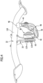
Fig. 1 als Ganzes mit 10 bezeichnetes Kraftfahrzeug umfasst eine Fahrzeugkarosserie 12, an welcher an einem Heckbereich 14 eine erfindungsgemäße Anhängekupplung 20 montiert ist, welche einen von einer Stoßfängereinheit 16 abgedeckten und sich quer zu einer Längsrichtung 18 der Fahrzeugkarosserie 12 und quer über dem Heckbereich 14 erstreckenden Querträger 22 sowie sich ungefähr parallel zur Längsrichtung 18 der Fahrzeugkarosserie 12 entlang von Karosseriewandabschnitten 26 erstreckende und an diesen fixierte Seitenträger 24 aufweist, die zusammen mit dem Querträger 22 eine Halteeinheit 28 bilden, welche zum Teil durch die Fahrzeugkarosserie 12 und zum Teil durch die Stoßfängereinheit 16 abgedeckt ist. - An der Halteeinheit 28 ist eine Haltebasis 32 einer als Ganzes mit 30 bezeichneten Lagereinheit, nämlich eine Schwenklagereinheit, vorgesehen, mit welcher ein als Ganzes mit 40 bezeichneter Kugelhals mit einem ersten Ende 42 verbunden ist, der außerdem an einem zweiten Ende 44 eine mit 46 bezeichnete Kupplungskugel trägt, wie in
Fig. 1 und2 dargestellt. - Durch die Schwenklagereinheit 30 besteht die Möglichkeit, den Kugelhals 40 von einer in
Fig. 2 und3 dargestellten Arbeitsstellung A, in welcher eine Kugelmittelachse 48 der Kupplungskugel 46 in einer zur Längsrichtung 18 parallelen, vertikalen Fahrzeuglängsmittelebene FL steht, um eine quer, insbesondere schräg, vorzugsweise in einem spitzen Winkel zur Fahrzeuglängsmittelebene FL verlaufende Schwenkachse 50 in eine inFig. 3 dargestellte Ruhestellung R zu verschwenken, in welcher ein Mittelabschnitt 52 des Kugelhalses sich quer zur Fahrzeuglängsmittelebene FL erstreckt und die Kupplungskugel 46 seitlich der Fahrzeuglängsmittelebene FL liegt, wie inFig. 3 dargestellt. - Insbesondere ist dabei der Kugelhals 40 in der Ruhestellung R in einer durch die Stoßfängereinheit 16 der Fahrzeugkarosserie 12 abgedeckten Stellung seitlich der Fahrzeuglängsmittelebene FL angeordnet.
- Bei einer derartigen Ausrichtung der Schwenkachse 50 besteht insbesondere die Möglichkeit, den Kugelhals 40 auf einer einer Fahrbahn 54 abgewandten Seite der Kupplungskugel 46 in der Ruhestellung anzuordnen, wie in
Fig. 3 gestrichelt dargestellt. - Zumindest besteht die Möglichkeit, den Kugelhals 40 in der Ruhestellung in einem derartigen Abstand von der Fahrbahn 54 anzuordnen, dass er höher liegt als eine Unterkante 56 der Stoßfängereinheit 16, bezogen auf den Verlauf der Fahrbahn 54.
- Wie in den
Fig. 3 bis 11 dargestellt, umfasst die Haltebasis 32 eine Flanscheinheit 62, auf welcher die Schwenklagereinheit 30 montiert ist, sowie sich von der Flanscheinheit 62 ausgehend erstreckende Halteelemente 64 und 66, die wie in denFig. 3 bis 11 dargestellt, sich ausgehend von der Flanscheinheit 62 sich zunehmend voneinander weg erstrecken und insbesondere ausgehend von einer geometrischen Mittelebene 68 der Flanscheinheit 62 mit zunehmendem Abstand von der Flanscheinheit 62 in zunehmendem Abstand von der Mittelebene 68 verlaufen, wie in denFig. 6 und9 dargestellt. - Vorzugsweise verläuft, wie in
Fig. 5 und6 dargestellt, die geometrische Mittelebene 68, wie inFig. 6 dargestellt, schräg zu einer Mittelachse 128 des Querträgers 22 in dem die Haltebasis 32 tragenden Bereich des Querträgers 22. - Insbesondere ist dabei die Haltebasis 32 gebildet durch zwei Elemente 74 und 76 aus Flachmaterial, die zwei Flanschelemente 84 und 86 aufweisen, welche mit einander zugewandten Anlageseiten 94 und 96 beispielsweise aneinander anliegen, wobei die Anlageseiten 94 und 96 jeweils an die Mittelebene 68 der Flanscheinheit 62 angrenzen, so dass beide Anlageseiten 94 und 96 letztlich angrenzend an die geometrische Mittelebene 68 angeordnet sind.
- Ausgehend von dem Flanschelement 84 umfasst das Element 74 das Halteelement 64, welches relativ zum Flanschelement 84 längs einer Biegelinie 104 gebogen ist und sich somit ausgehend von der Biegelinie 104 in einem Winkel zur Mittelebene 68 und mit zunehmendem Abstand von der Biegelinie 104 mit zunehmendem Abstand von der Mittelebene 68 verläuft.
- Vorzugsweise ist dabei das Halteelement 64 ebenfalls ein Teil aus dem Flachmaterial, aus welchem das Element 74 gebildet ist, so dass - wie in
Fig. 8 bis 11 dargestellt - das Flanschelement 84 und das Halteelement 64 jeweils Flachmaterialteile sind, die über einen durch die Biegelinie 104 vorgegebenen Biegebereich 102 einstückig ineinander übergehen, wobei die Flachmaterialteile einen stumpfen Winkel α miteinander einschließen, der im Bereich von 100 Grad bis 170 Grad liegt. - Der spitze Winkel β, in welchem das Halteelement 64 relativ zu der Anlageseite 94 und somit zur Mittelebene 68 verläuft, liegt im Bereich von 10 Grad bis 80 Grad, vorzugsweise im Bereich von 20 Grad bis 60 Grad.
- Auch das Halteelement 66 ist - wie in
Fig. 8 und9 dargestellt - Teil des Elements 76, welches das Flanschelement 86 umfasst relativ zu welchem das Halteelement 66 ausgehend von einer Biegelinie 106 in einem Winkel verläuft. - Das Element 76 ist ebenfalls aus Flachmaterial gebildet, wobei das Flanschelement 86 und das Halteelement 66 über einen durch die Biegelinie 106 vorgegebenen Biegebereich 108 ineinander übergehen und die Flachmaterialteile einen stumpfen Winkel miteinander einschließen, der ebenfalls im Bereich von 100 Grad bis 170 Grad liegt.
- Insbesondere verläuft das Halteelement 66 relativ zu der Anlageseite 96 des Flanschelements 66 ausgehend von der Biegelinie 106 in einem Winkel, der im Bereich von 10 Grad bis 80 Grad liegt, vorzugsweise im Bereich von 20 Grad bis 60 Grad.
- Somit verläuft ebenfalls das Halteelement 66 ausgehend von der Biegelinie 106 in einem spitzen Winkel relativ zur Mittelebene 68.
- Wie aus der Projektion gemäß
Fig. 8 ersichtlich, verlaufen die Biegelinien 104 und 106 nicht parallel zueinander, sondern deren Projektion auf die Mittelebene 68, welche inFig. 6 die Zeichenebene darstellt, ergibt einen spitzen Winkel γ zwischen den Biegelinien 104 und 106, der im Bereich zwischen 15 Grad und 140 Grad liegt, vorzugsweise im Bereich zwischen 40 Grad und 100 Grad. - Die Flanschelemente 84 und 86 sind ihrerseits mit identisch angeordneten Durchbrüchen 112 versehen, die um die Schwenkachse 50 herum, vorzugsweise auf einer Kreislinie um die Schwenkachse 50, angeordnet sind und dazu dienen, Montageschrauben aufzunehmen, mit welchen die Schwenklagereinheit 30 an der Flanscheinheit 62 montierbar ist.
- Prinzipiell wäre es denkbar, die Flanschelemente 84 und 86, beispielsweise durch Punktschweißung oder durch Kleben flächig, miteinander zu verbinden.
- Eine derartige Verbindung ist jedoch nicht erforderlich, da die Durchbrüche 112 durchsetzende Schrauben 113 zur Montage der Schwenklagereinheit 30 gleichzeitig auch die beiden Flanschelemente 84 und 86 derart miteinander verspannen, dass diese durch die Montage der Schwenklagereinheit 30 an der Flanscheinheit 62 fest miteinander verbunden werden.
- Zur Verbindung mit dem Querträger 22 sind die Halteelemente 64, 66 mit Querträgeraufnahmen 114, 116 versehen (
Fig. 7 bis 9 ), die durch Ausschnitte aus dem die Halteelemente 64, 66 bildenden Flachmaterial hergestellt werden, wobei der Verlauf von durch die Ausschnitte gebildeten Randkonturen 124, 126 der Querträgeraufnahmen 114 und 116 an eine Außenumfangsfläche 118 des Querträgers 22 angepasst ist, an welcher die Querträgeraufnahmen 114 und 116 vorzugsweise mit ihren Randkonturen 124 und 126 linienförmig anliegen, und entlang den linienförmig anliegenden Randkonturen 124 und 126 mit dem Querträger 22 verschweißt werden, wobei vorzugsweise eine linienförmige Schweißverbindung entsteht. - Vorzugsweise sind die Querträgeraufnahmen 114 und 116 so ausgebildet, dass diese, wie in
Fig. 6 und7 dargestellt, die Außenumfangsfläche 118 des Querträgers 22 in einem Umfangsbereich umfassen, welcher sich über mehr als einen Winkelbereich von 120 Grad um eine Mittelachse des Querträgers, vorzugsweise ein Winkelbereich von mehr als 150 Grad um die Mittelachse 128 des Querträgers 22 erstreckt. - Die erfindungsgemäße Haltebasis 32 erlaubt durch die auseinandergespreizt zueinander verlaufenden Halteelemente 64 und 66 eine stabile und insbesondere biegesteife Verbindung zwischen der Haltebasis 32 und dem Querträger 22 und ist außerdem einfach dadurch herstellbar, dass sie zwei Elemente 74 und 76 aus einem plattenförmigen Flachmaterial umfasst, bei denen jeweils das Halteelement 64, 66 relativ zum die Flanscheinheit 62 bildenden Flanschelement 84 und 86 längs einer Biegelinie 104, 106 abgebogen ist, um einerseits bei beispielsweise miteinander zur Flanscheinheit 62 verbundenen, aneinander anliegenden Flanschelementen 84 und 86 den sich aufspreizenden Verlauf der Halteelemente 84 und 86 zu erhalten.
- Bei einem zweiten Ausführungsbeispiel einer erfindungsgemäßen Anhängekupplung umfasst die Haltebasis 32' eine Flanscheinheit 62', die aus mehr als zwei, beispielsweise vier, Elementen 74', 75', 76' und 77' aus Flachmaterial ausgebildet ist, wobei jedes der Elemente 74' bis 77' ein Halteelement 64', 65', 66' und 67' sowie ein entsprechendes Flanschelement 84', 85', 86', 87' aufweist.
- Alle Flanschelemente 84', 85', 86', 87' verlaufen parallel zur Mittelebene 68' und liegen insbesondere flächig aneinander an, um die Flanscheinheit 62' zu bilden, die die Lagereinheit 30 trägt.
- Die Halteelemente 64', 65', 66' und 67' schließen mit den Flanschelementen 84', 85', 86', 87' einen stumpfen Winkel ein.
- Insbesondere verlaufen auch bei dem zweiten Ausführungsbeispiel, wie in
Fig. 11 dargestellt, die Halteelemente 64', 65', 66', 67' mit zunehmendem Abstand von der Flanscheinheit 62' in zunehmendem Abstand voneinander. - Im Übrigen sind bei dem zweiten Ausführungsbeispiel diejenigen Merkmale, die nicht gesondert erwähnt wurden mit denen des ersten Ausführungsbeispiels identisch oder ähnlich, so dass auf die Ausführungen zum ersten Ausführungsbeispiel vollinhaltlich Bezug genommen werden kann.
Claims (15)
- Anhängekupplung für Kraftfahrzeuge, umfassend einen mit einer Kraftfahrzeugkarosserie (12) verbindbaren Querträger (22) und eine Lagereinheit (30), welche einen Kugelhals (40) trägt, der an einem ersten Ende (42) mit der Lagereinheit (30) verbunden ist und an einem zweiten Ende (44) eine Kupplungskugel (46) trägt, und eine die Lagereinheit (30) tragende und mit dem Querträger (22) verbundene Haltebasis (32), wobei die Haltebasis (32) eine Flanscheinheit (62) zur Aufnahme der Lagereinheit (30) sowie zwei sich von der Flanscheinheit (62) ausgehende und dabei im Abstand zueinander verlaufende Halteelemente (64, 66) aufweist, die an dem Querträger (22) angreifen, wobei die Haltebasis (32) durch zwei Elemente (74, 76) aus Flachmaterial gebildet ist, von denen jedes ein Flanschelement (84, 86) umfasst, welches zur Bildung der Flanscheinheit (62) beiträgt, und von denen jede eines der Halteelemente (64, 66) bildet, die sich von der Flanscheinheit (62) ausgehend in Richtung des Querträgers (22) erstrecken und wobei jedes der Halteelemente (64, 66) fest mit dem jeweiligen Flanschelement (84, 86) verbunden ist, wobei die Halteelemente (64, 66) relativ zu den entsprechenden Flanschelementen (84, 86) längs einer Biegelinie (104, 106) umgebogen sind, wobei das Halteelement (64, 66) und das jeweilige Flanschelement (84, 86) des jeweiligen Elements (74, 76) einen stumpfen Winkel miteinander einschließen,
dadurch gekennzeichnet, dass die Lagereinheit (30) eine Schwenklagereinheit (30) ist, welche auf der Flanscheinheit (62) montiert ist, dass die Projektion der Biegelinien (104, 106) der Elemente (74, 76) auf die Mittelebene (68) einen sich schneidenden Verlauf der projizierten Biegelinien (104', 106') ergibt. - Anhängekupplung nach Anspruch 1, dadurch gekennzeichnet, dass die Flanscheinheit (62) aus den Flanschelementen (84, 86) derart gebildet ist, dass die Flanschelemente (84, 86) mit einander zugewandten Anlageseiten (94, 96) aneinander anliegen.
- Anhängekupplung nach Anspruch 1 oder 2, dadurch gekennzeichnet, dass jedes der Halteelemente (64, 66) einstückig in das jeweilige Flanschelement (84, 86) übergeht.
- Anhängekupplung nach einem der Ansprüche 1 bis 3, dadurch gekennzeichnet, dass jedes der Halteelemente (64, 66) relativ zum entsprechenden Flanschelement (84, 86) so angeordnet ist, dass es über einen Biegebereich (102, 108) in das jeweilige Flanschelement (84, 86) übergeht.
- Anhängekupplung nach einem der voranstehenden Ansprüche, dadurch gekennzeichnet, dass die Halteelemente (64, 66) mit zunehmendem Abstand von der Flanscheinheit (62) in zunehmendem Abstand voneinander verlaufen.
- Anhängekupplung nach einem der voranstehenden Ansprüche, dadurch gekennzeichnet, dass die jeweiligen Halteelemente (64, 66) sich mit zunehmender Erstreckung von der Flanscheinheit (62) weg in zunehmendem Abstand von einer Mittelebene (68) der Flanscheinheit (62) erstrecken.
- Anhängekupplung nach einem der voranstehenden Ansprüche, dadurch gekennzeichnet, dass die Halteelemente (64, 66) in einem spitzen Winkel zu einer Mittelebene (68) der Flanscheinheit (68) verlaufen.
- Anhängekupplung nach einem der voranstehenden Ansprüche, dadurch gekennzeichnet, dass der stumpfe Winkel zwischen dem jeweiligen Halteelement (64, 66) und dem jeweiligen Flanschelement (84, 86) im Bereich zwischen 100 Grad und 170 Grad liegt.
- Anhängekupplung nach einem der voranstehenden Ansprüche, dadurch gekennzeichnet, dass die projizierten Biegelinien (104', 106') einen spitzen Winkel miteinander einschließen und dass insbesondere der spitze Winkel im Bereich zwischen 15 Grad und 140 Grad liegt.
- Anhängekupplung nach einem der voranstehenden Ansprüche, dadurch gekennzeichnet, dass die Halteelemente (64, 66) an einer Außenumfangsfläche (118) des Querträgers (22) anliegen.
- Anhängekupplung nach Anspruch 10, dadurch gekennzeichnet, dass die Halteelemente (64, 66) mit Querträgeraufnahmen (114, 116) versehen sind, die an der Außenumfangsfläche (118) des Querträgers (22) anliegen.
- Anhängekupplung nach einem der voranstehenden Ansprüche, dadurch gekennzeichnet, dass die Querträgeraufnahmen (114, 116) als in den Halteelementen (64, 66) vorgesehene Ausschnitte ausgeführt, so dass sich die Halteelemente (64, 66) im Bereich der Querträgeraufnahmen (114, 116) quer zu dem Querträger (22), insbesondere in einem von 90° abweichenden Winkel, erstrecken.
- Anhängekupplung nach einem der voranstehenden Ansprüche, dadurch gekennzeichnet, dass die Querträgeraufnahmen (114, 116) durch Randkonturen der Halteelemente (64, 66) gebildet sind, welche an der Außenumfangsfläche (118) des Querträgers (22) anliegen.
- Anhängekupplung nach Anspruch 13, dadurch gekennzeichnet, dass die Querträgeraufnahmen (114, 116) längs ihrer Randkonturen an der Außenumfangsfläche (118) anliegen.
- Anhängekupplung nach einem der Ansprüche 11 bis 14, dadurch gekennzeichnet, dass die Querträgeraufnahmen (114, 116) die Außenumfangsfläche (118) des Querträgers (22) über einen Winkelbereich von mindestens 120 Grad, bezogen auf eine Mittelachse des Querträgers (22), umfassen und dass insbesondere die Querträgeraufnahmen (114, 116) die Außenumfangsfläche (118) des Querträgers (22) über einen Winkel von mindestens 150°, noch besser von mindestens 180°, umfassen und dass insbesondere die Querträgeraufnahmen (114, 116) längs ihrer Randkontur linienförmig mit dem Querträger (22) verschweißt sind.
Applications Claiming Priority (1)
| Application Number | Priority Date | Filing Date | Title |
|---|---|---|---|
| DE102015100490.9A DE102015100490A1 (de) | 2015-01-14 | 2015-01-14 | Anhängekupplung |
Publications (3)
| Publication Number | Publication Date |
|---|---|
| EP3045328A1 EP3045328A1 (de) | 2016-07-20 |
| EP3045328B1 EP3045328B1 (de) | 2019-04-03 |
| EP3045328B2 true EP3045328B2 (de) | 2023-03-15 |
Family
ID=55129650
Family Applications (1)
| Application Number | Title | Priority Date | Filing Date |
|---|---|---|---|
| EP16151064.9A Active EP3045328B2 (de) | 2015-01-14 | 2016-01-13 | Anhängekupplung |
Country Status (3)
| Country | Link |
|---|---|
| US (1) | US9849741B2 (de) |
| EP (1) | EP3045328B2 (de) |
| DE (1) | DE102015100490A1 (de) |
Families Citing this family (4)
| Publication number | Priority date | Publication date | Assignee | Title |
|---|---|---|---|---|
| DE102016117017A1 (de) | 2016-09-09 | 2018-03-15 | Westfalia-Automotive Gmbh | Anhängekupplung mit einem Kupplungsarm |
| DE102017121369A1 (de) | 2017-09-14 | 2019-03-14 | ACPS Automotive GmbH | Anhängekupplung |
| DE102017121357A1 (de) * | 2017-09-14 | 2019-03-14 | ACPS Automotive GmbH | Anhängekupplung |
| FR3071436B1 (fr) * | 2017-09-26 | 2020-04-03 | Renault S.A.S | Agencement de montage d'une traverse d'attelage sur une caisse de vehicule automobile. |
Citations (4)
| Publication number | Priority date | Publication date | Assignee | Title |
|---|---|---|---|---|
| US2944836A (en) † | 1958-08-07 | 1960-07-12 | Dalton Foundries Inc | Retractable trailer hitches |
| EP0799732A1 (de) † | 1996-04-01 | 1997-10-08 | ORIS FAHRZEUGTEILE HANS RIEHLE GmbH | Anhängerkupplung |
| EP1428697A1 (de) † | 2002-11-13 | 2004-06-16 | Westfalia Automotive GmbH & Co. KG | Anhängekupplung für Kraftfahrzeuge |
| WO2006068479A1 (en) † | 2004-12-24 | 2006-06-29 | Thule Towing Systems B.V. | Ratractable tow hitch |
Family Cites Families (15)
| Publication number | Priority date | Publication date | Assignee | Title |
|---|---|---|---|---|
| US2642295A (en) | 1952-09-08 | 1953-06-16 | Fulton Co | Vehicle tow coupling |
| SE390143B (sv) | 1975-05-06 | 1976-12-06 | Volvo Ab | Draganordning ffor motorfordon |
| DE102004004503B4 (de) * | 2004-01-22 | 2022-01-20 | ACPS Automotive GmbH | Anhängekupplung |
| DE102005032474A1 (de) * | 2005-07-07 | 2007-01-11 | Oris Fahrzeugteile Hans Riehle Gmbh | Anhängevorrichtung |
| DE102005053177A1 (de) * | 2005-11-03 | 2007-05-10 | Scambia Industrial Developments Aktiengesellschaft | Betätigungseinrichtung |
| DE102006035261A1 (de) * | 2006-07-29 | 2008-01-31 | Scambia Industrial Developments Aktiengesellschaft | Anhängekupplung |
| JP4377930B2 (ja) * | 2007-06-21 | 2009-12-02 | 本田技研工業株式会社 | 車体パネル |
| DE102008012622A1 (de) * | 2008-02-28 | 2009-09-10 | Scambia Industrial Developments Aktiengesellschaft | Anhängekupplung |
| DE102008030626A1 (de) * | 2008-06-23 | 2009-12-31 | Scambia Industrial Developments Aktiengesellschaft | Anhängekupplung |
| JP5327319B2 (ja) * | 2009-05-22 | 2013-10-30 | トヨタ自動車株式会社 | 車両ボディ構造 |
| DE102009035334A1 (de) * | 2009-07-21 | 2011-01-27 | Scambia Industrial Developments Aktiengesellschaft | Anhängekupplung für Kraftfahrzeuge |
| DE102010054208B4 (de) | 2010-12-11 | 2015-05-28 | Westfalia-Automotive Gmbh | Steuereinrichtung für eine Anhängerkupplung eines Kraftfahrzeugs |
| DE102011053506A1 (de) * | 2011-09-12 | 2013-03-14 | Scambia Holdings Cyprus Ltd. | Anhängekupplung |
| FR2983125B1 (fr) * | 2011-11-25 | 2014-05-02 | Ur Ben | Ensemble d'attelage pour vehicule automobile de traction |
| DE102013100777A1 (de) | 2013-01-25 | 2014-07-31 | Scambia Holdings Cyprus Limited | Anhängekupplung |
-
2015
- 2015-01-14 DE DE102015100490.9A patent/DE102015100490A1/de not_active Ceased
-
2016
- 2016-01-13 US US14/994,891 patent/US9849741B2/en active Active
- 2016-01-13 EP EP16151064.9A patent/EP3045328B2/de active Active
Patent Citations (4)
| Publication number | Priority date | Publication date | Assignee | Title |
|---|---|---|---|---|
| US2944836A (en) † | 1958-08-07 | 1960-07-12 | Dalton Foundries Inc | Retractable trailer hitches |
| EP0799732A1 (de) † | 1996-04-01 | 1997-10-08 | ORIS FAHRZEUGTEILE HANS RIEHLE GmbH | Anhängerkupplung |
| EP1428697A1 (de) † | 2002-11-13 | 2004-06-16 | Westfalia Automotive GmbH & Co. KG | Anhängekupplung für Kraftfahrzeuge |
| WO2006068479A1 (en) † | 2004-12-24 | 2006-06-29 | Thule Towing Systems B.V. | Ratractable tow hitch |
Also Published As
| Publication number | Publication date |
|---|---|
| EP3045328B1 (de) | 2019-04-03 |
| DE102015100490A1 (de) | 2016-07-14 |
| US9849741B2 (en) | 2017-12-26 |
| US20160200158A1 (en) | 2016-07-14 |
| EP3045328A1 (de) | 2016-07-20 |
Similar Documents
| Publication | Publication Date | Title |
|---|---|---|
| EP0518165B1 (de) | Fahrzeugaufbau | |
| EP2095978B1 (de) | Anhängekupplung | |
| EP2322332B1 (de) | Fahrmischer mit einem Fahrgestell | |
| EP3045328B2 (de) | Anhängekupplung | |
| WO2017016651A1 (de) | Vorrichtung zum halten eines bauteils | |
| WO2015007631A1 (de) | Rückenlehnenstruktur für einen fahrzeugsitz und fahrzeugsitz | |
| DE102011112418A1 (de) | Vorrichtung zur Befestigung einer Kopfstütze an einem Fahrzeugsitz und Fahrzeugsitz mit Kopfstütze | |
| EP2759422B1 (de) | Anhängekupplung | |
| EP2508407A1 (de) | Gerüst, insbesondere für elektrische Einrichtungen in einem Schienenfahrzeug, und Verfahren zur Herstellung des Gerüsts | |
| EP2730457A1 (de) | Antrieb einer Sitzverstelleinrichtung für Kraftfahrzeuge | |
| WO2016026745A1 (de) | Aggregatlager-anordnung | |
| DE102015118505B4 (de) | Befestigungsvorrichtung | |
| EP3964369B1 (de) | Montagesystem | |
| DE102017117502B4 (de) | Lenksäulen-Klemmträger sowie Verstellvorrichtung | |
| DE102008026618B4 (de) | Positioniereinrichtung | |
| DE102014218605B4 (de) | Vorrichtung zur Befestigung einer Hinterachse an einem karosseriebaufesten Querträger eines Kraftfahrzeugs und Anordnung einer solchen Vorrichtung in einem Kraftfahrzeug | |
| DE19623691C2 (de) | Haltevorrichtung für Fahrzeugzubehör oder Fahrzeugzusatzeinrichtungen | |
| DE102021133348A1 (de) | Anhängekupplung für Kraftfahrzeuge | |
| DE102022119905A1 (de) | Anhängekupplung | |
| DE102004020746A1 (de) | Schutzvorrichtung für Kraftfahrzeuge | |
| DE102022119904A1 (de) | Anhängekupplung | |
| DE102020111069A1 (de) | Blattfeder | |
| EP2390119A1 (de) | Heckanbauvorrichtung | |
| DE102009005477A1 (de) | Halterungseinrichtung für eine Schutzwandanordnung und Schutzwandanordnung mit einer derartigen Halterungseinrichtung | |
| DE29504839U1 (de) | Verbinder für Gitterkabelbahnen |
Legal Events
| Date | Code | Title | Description |
|---|---|---|---|
| PUAI | Public reference made under article 153(3) epc to a published international application that has entered the european phase |
Free format text: ORIGINAL CODE: 0009012 |
|
| AK | Designated contracting states |
Kind code of ref document: A1 Designated state(s): AL AT BE BG CH CY CZ DE DK EE ES FI FR GB GR HR HU IE IS IT LI LT LU LV MC MK MT NL NO PL PT RO RS SE SI SK SM TR |
|
| AX | Request for extension of the european patent |
Extension state: BA ME |
|
| STAA | Information on the status of an ep patent application or granted ep patent |
Free format text: STATUS: REQUEST FOR EXAMINATION WAS MADE |
|
| 17P | Request for examination filed |
Effective date: 20170119 |
|
| RBV | Designated contracting states (corrected) |
Designated state(s): AL AT BE BG CH CY CZ DE DK EE ES FI FR GB GR HR HU IE IS IT LI LT LU LV MC MK MT NL NO PL PT RO RS SE SI SK SM TR |
|
| RAP1 | Party data changed (applicant data changed or rights of an application transferred) |
Owner name: BOSAL ACPS HOLDING 2 B.V. |
|
| GRAP | Despatch of communication of intention to grant a patent |
Free format text: ORIGINAL CODE: EPIDOSNIGR1 |
|
| STAA | Information on the status of an ep patent application or granted ep patent |
Free format text: STATUS: GRANT OF PATENT IS INTENDED |
|
| RIC1 | Information provided on ipc code assigned before grant |
Ipc: B60D 1/06 20060101AFI20181002BHEP Ipc: B60D 1/48 20060101ALI20181002BHEP |
|
| INTG | Intention to grant announced |
Effective date: 20181026 |
|
| GRAS | Grant fee paid |
Free format text: ORIGINAL CODE: EPIDOSNIGR3 |
|
| GRAA | (expected) grant |
Free format text: ORIGINAL CODE: 0009210 |
|
| STAA | Information on the status of an ep patent application or granted ep patent |
Free format text: STATUS: THE PATENT HAS BEEN GRANTED |
|
| AK | Designated contracting states |
Kind code of ref document: B1 Designated state(s): AL AT BE BG CH CY CZ DE DK EE ES FI FR GB GR HR HU IE IS IT LI LT LU LV MC MK MT NL NO PL PT RO RS SE SI SK SM TR |
|
| REG | Reference to a national code |
Ref country code: GB Ref legal event code: FG4D Free format text: NOT ENGLISH |
|
| REG | Reference to a national code |
Ref country code: CH Ref legal event code: EP Ref country code: AT Ref legal event code: REF Ref document number: 1115263 Country of ref document: AT Kind code of ref document: T Effective date: 20190415 |
|
| REG | Reference to a national code |
Ref country code: DE Ref legal event code: R096 Ref document number: 502016003944 Country of ref document: DE |
|
| REG | Reference to a national code |
Ref country code: IE Ref legal event code: FG4D Free format text: LANGUAGE OF EP DOCUMENT: GERMAN |
|
| REG | Reference to a national code |
Ref country code: NL Ref legal event code: MP Effective date: 20190403 |
|
| REG | Reference to a national code |
Ref country code: LT Ref legal event code: MG4D |
|
| PG25 | Lapsed in a contracting state [announced via postgrant information from national office to epo] |
Ref country code: NL Free format text: LAPSE BECAUSE OF FAILURE TO SUBMIT A TRANSLATION OF THE DESCRIPTION OR TO PAY THE FEE WITHIN THE PRESCRIBED TIME-LIMIT Effective date: 20190403 |
|
| RAP2 | Party data changed (patent owner data changed or rights of a patent transferred) |
Owner name: ACPS AUTOMOTIVE GMBH |
|
| PG25 | Lapsed in a contracting state [announced via postgrant information from national office to epo] |
Ref country code: FI Free format text: LAPSE BECAUSE OF FAILURE TO SUBMIT A TRANSLATION OF THE DESCRIPTION OR TO PAY THE FEE WITHIN THE PRESCRIBED TIME-LIMIT Effective date: 20190403 Ref country code: NO Free format text: LAPSE BECAUSE OF FAILURE TO SUBMIT A TRANSLATION OF THE DESCRIPTION OR TO PAY THE FEE WITHIN THE PRESCRIBED TIME-LIMIT Effective date: 20190703 Ref country code: LT Free format text: LAPSE BECAUSE OF FAILURE TO SUBMIT A TRANSLATION OF THE DESCRIPTION OR TO PAY THE FEE WITHIN THE PRESCRIBED TIME-LIMIT Effective date: 20190403 Ref country code: HR Free format text: LAPSE BECAUSE OF FAILURE TO SUBMIT A TRANSLATION OF THE DESCRIPTION OR TO PAY THE FEE WITHIN THE PRESCRIBED TIME-LIMIT Effective date: 20190403 Ref country code: SE Free format text: LAPSE BECAUSE OF FAILURE TO SUBMIT A TRANSLATION OF THE DESCRIPTION OR TO PAY THE FEE WITHIN THE PRESCRIBED TIME-LIMIT Effective date: 20190403 Ref country code: ES Free format text: LAPSE BECAUSE OF FAILURE TO SUBMIT A TRANSLATION OF THE DESCRIPTION OR TO PAY THE FEE WITHIN THE PRESCRIBED TIME-LIMIT Effective date: 20190403 Ref country code: PT Free format text: LAPSE BECAUSE OF FAILURE TO SUBMIT A TRANSLATION OF THE DESCRIPTION OR TO PAY THE FEE WITHIN THE PRESCRIBED TIME-LIMIT Effective date: 20190803 Ref country code: AL Free format text: LAPSE BECAUSE OF FAILURE TO SUBMIT A TRANSLATION OF THE DESCRIPTION OR TO PAY THE FEE WITHIN THE PRESCRIBED TIME-LIMIT Effective date: 20190403 |
|
| PG25 | Lapsed in a contracting state [announced via postgrant information from national office to epo] |
Ref country code: LV Free format text: LAPSE BECAUSE OF FAILURE TO SUBMIT A TRANSLATION OF THE DESCRIPTION OR TO PAY THE FEE WITHIN THE PRESCRIBED TIME-LIMIT Effective date: 20190403 Ref country code: RS Free format text: LAPSE BECAUSE OF FAILURE TO SUBMIT A TRANSLATION OF THE DESCRIPTION OR TO PAY THE FEE WITHIN THE PRESCRIBED TIME-LIMIT Effective date: 20190403 Ref country code: BG Free format text: LAPSE BECAUSE OF FAILURE TO SUBMIT A TRANSLATION OF THE DESCRIPTION OR TO PAY THE FEE WITHIN THE PRESCRIBED TIME-LIMIT Effective date: 20190703 Ref country code: PL Free format text: LAPSE BECAUSE OF FAILURE TO SUBMIT A TRANSLATION OF THE DESCRIPTION OR TO PAY THE FEE WITHIN THE PRESCRIBED TIME-LIMIT Effective date: 20190403 Ref country code: GR Free format text: LAPSE BECAUSE OF FAILURE TO SUBMIT A TRANSLATION OF THE DESCRIPTION OR TO PAY THE FEE WITHIN THE PRESCRIBED TIME-LIMIT Effective date: 20190704 |
|
| PG25 | Lapsed in a contracting state [announced via postgrant information from national office to epo] |
Ref country code: IS Free format text: LAPSE BECAUSE OF FAILURE TO SUBMIT A TRANSLATION OF THE DESCRIPTION OR TO PAY THE FEE WITHIN THE PRESCRIBED TIME-LIMIT Effective date: 20190803 |
|
| REG | Reference to a national code |
Ref country code: DE Ref legal event code: R026 Ref document number: 502016003944 Country of ref document: DE |
|
| PLBI | Opposition filed |
Free format text: ORIGINAL CODE: 0009260 |
|
| PLAX | Notice of opposition and request to file observation + time limit sent |
Free format text: ORIGINAL CODE: EPIDOSNOBS2 |
|
| PG25 | Lapsed in a contracting state [announced via postgrant information from national office to epo] |
Ref country code: SK Free format text: LAPSE BECAUSE OF FAILURE TO SUBMIT A TRANSLATION OF THE DESCRIPTION OR TO PAY THE FEE WITHIN THE PRESCRIBED TIME-LIMIT Effective date: 20190403 Ref country code: DK Free format text: LAPSE BECAUSE OF FAILURE TO SUBMIT A TRANSLATION OF THE DESCRIPTION OR TO PAY THE FEE WITHIN THE PRESCRIBED TIME-LIMIT Effective date: 20190403 Ref country code: EE Free format text: LAPSE BECAUSE OF FAILURE TO SUBMIT A TRANSLATION OF THE DESCRIPTION OR TO PAY THE FEE WITHIN THE PRESCRIBED TIME-LIMIT Effective date: 20190403 Ref country code: RO Free format text: LAPSE BECAUSE OF FAILURE TO SUBMIT A TRANSLATION OF THE DESCRIPTION OR TO PAY THE FEE WITHIN THE PRESCRIBED TIME-LIMIT Effective date: 20190403 |
|
| 26 | Opposition filed |
Opponent name: WESTFALIA - AUTOMOTIVE GMBH Effective date: 20200102 |
|
| PG25 | Lapsed in a contracting state [announced via postgrant information from national office to epo] |
Ref country code: IT Free format text: LAPSE BECAUSE OF FAILURE TO SUBMIT A TRANSLATION OF THE DESCRIPTION OR TO PAY THE FEE WITHIN THE PRESCRIBED TIME-LIMIT Effective date: 20190403 Ref country code: SM Free format text: LAPSE BECAUSE OF FAILURE TO SUBMIT A TRANSLATION OF THE DESCRIPTION OR TO PAY THE FEE WITHIN THE PRESCRIBED TIME-LIMIT Effective date: 20190403 |
|
| PG25 | Lapsed in a contracting state [announced via postgrant information from national office to epo] |
Ref country code: TR Free format text: LAPSE BECAUSE OF FAILURE TO SUBMIT A TRANSLATION OF THE DESCRIPTION OR TO PAY THE FEE WITHIN THE PRESCRIBED TIME-LIMIT Effective date: 20190403 |
|
| PLBB | Reply of patent proprietor to notice(s) of opposition received |
Free format text: ORIGINAL CODE: EPIDOSNOBS3 |
|
| PG25 | Lapsed in a contracting state [announced via postgrant information from national office to epo] |
Ref country code: SI Free format text: LAPSE BECAUSE OF FAILURE TO SUBMIT A TRANSLATION OF THE DESCRIPTION OR TO PAY THE FEE WITHIN THE PRESCRIBED TIME-LIMIT Effective date: 20190403 |
|
| REG | Reference to a national code |
Ref country code: DE Ref legal event code: R081 Ref document number: 502016003944 Country of ref document: DE Owner name: ACPS AUTOMOTIVE GMBH, DE Free format text: FORMER OWNER: BOSAL ACPS HOLDING 2 B.V., VIANEN, NL Ref country code: DE Ref legal event code: R082 Ref document number: 502016003944 Country of ref document: DE Representative=s name: HOEGER, STELLRECHT & PARTNER PATENTANWAELTE MB, DE |
|
| PG25 | Lapsed in a contracting state [announced via postgrant information from national office to epo] |
Ref country code: MC Free format text: LAPSE BECAUSE OF FAILURE TO SUBMIT A TRANSLATION OF THE DESCRIPTION OR TO PAY THE FEE WITHIN THE PRESCRIBED TIME-LIMIT Effective date: 20190403 |
|
| REG | Reference to a national code |
Ref country code: CH Ref legal event code: PL |
|
| REG | Reference to a national code |
Ref country code: BE Ref legal event code: MM Effective date: 20200131 |
|
| PG25 | Lapsed in a contracting state [announced via postgrant information from national office to epo] |
Ref country code: LU Free format text: LAPSE BECAUSE OF NON-PAYMENT OF DUE FEES Effective date: 20200113 |
|
| PG25 | Lapsed in a contracting state [announced via postgrant information from national office to epo] |
Ref country code: BE Free format text: LAPSE BECAUSE OF NON-PAYMENT OF DUE FEES Effective date: 20200131 Ref country code: CH Free format text: LAPSE BECAUSE OF NON-PAYMENT OF DUE FEES Effective date: 20200131 Ref country code: LI Free format text: LAPSE BECAUSE OF NON-PAYMENT OF DUE FEES Effective date: 20200131 |
|
| PG25 | Lapsed in a contracting state [announced via postgrant information from national office to epo] |
Ref country code: IE Free format text: LAPSE BECAUSE OF NON-PAYMENT OF DUE FEES Effective date: 20200113 |
|
| REG | Reference to a national code |
Ref country code: AT Ref legal event code: MM01 Ref document number: 1115263 Country of ref document: AT Kind code of ref document: T Effective date: 20210113 |
|
| REG | Reference to a national code |
Ref country code: GB Ref legal event code: 732E Free format text: REGISTERED BETWEEN 20220224 AND 20220302 |
|
| PG25 | Lapsed in a contracting state [announced via postgrant information from national office to epo] |
Ref country code: AT Free format text: LAPSE BECAUSE OF NON-PAYMENT OF DUE FEES Effective date: 20210113 |
|
| PG25 | Lapsed in a contracting state [announced via postgrant information from national office to epo] |
Ref country code: MT Free format text: LAPSE BECAUSE OF FAILURE TO SUBMIT A TRANSLATION OF THE DESCRIPTION OR TO PAY THE FEE WITHIN THE PRESCRIBED TIME-LIMIT Effective date: 20190403 Ref country code: CY Free format text: LAPSE BECAUSE OF FAILURE TO SUBMIT A TRANSLATION OF THE DESCRIPTION OR TO PAY THE FEE WITHIN THE PRESCRIBED TIME-LIMIT Effective date: 20190403 |
|
| PG25 | Lapsed in a contracting state [announced via postgrant information from national office to epo] |
Ref country code: MK Free format text: LAPSE BECAUSE OF FAILURE TO SUBMIT A TRANSLATION OF THE DESCRIPTION OR TO PAY THE FEE WITHIN THE PRESCRIBED TIME-LIMIT Effective date: 20190403 |
|
| APAH | Appeal reference modified |
Free format text: ORIGINAL CODE: EPIDOSCREFNO |
|
| APBM | Appeal reference recorded |
Free format text: ORIGINAL CODE: EPIDOSNREFNO |
|
| APBP | Date of receipt of notice of appeal recorded |
Free format text: ORIGINAL CODE: EPIDOSNNOA2O |
|
| APBU | Appeal procedure closed |
Free format text: ORIGINAL CODE: EPIDOSNNOA9O |
|
| REG | Reference to a national code |
Ref country code: DE Ref legal event code: R081 Ref document number: 502016003944 Country of ref document: DE Owner name: ACPS AUTOMOTIVE GMBH, DE Free format text: FORMER OWNER: ACPS AUTOMOTIVE GMBH, 71706 MARKGROENINGEN, DE |
|
| RAP4 | Party data changed (patent owner data changed or rights of a patent transferred) |
Owner name: ACPS AUTOMOTIVE GMBH |
|
| PUAH | Patent maintained in amended form |
Free format text: ORIGINAL CODE: 0009272 |
|
| STAA | Information on the status of an ep patent application or granted ep patent |
Free format text: STATUS: PATENT MAINTAINED AS AMENDED |
|
| 27A | Patent maintained in amended form |
Effective date: 20230315 |
|
| AK | Designated contracting states |
Kind code of ref document: B2 Designated state(s): AL AT BE BG CH CY CZ DE DK EE ES FI FR GB GR HR HU IE IS IT LI LT LU LV MC MK MT NL NO PL PT RO RS SE SI SK SM TR |
|
| REG | Reference to a national code |
Ref country code: DE Ref legal event code: R102 Ref document number: 502016003944 Country of ref document: DE |
|
| P01 | Opt-out of the competence of the unified patent court (upc) registered |
Effective date: 20230517 |
|
| PGFP | Annual fee paid to national office [announced via postgrant information from national office to epo] |
Ref country code: GB Payment date: 20260123 Year of fee payment: 11 |
|
| PGFP | Annual fee paid to national office [announced via postgrant information from national office to epo] |
Ref country code: DE Payment date: 20260121 Year of fee payment: 11 |
|
| PGFP | Annual fee paid to national office [announced via postgrant information from national office to epo] |
Ref country code: FR Payment date: 20260123 Year of fee payment: 11 |
|
| PGFP | Annual fee paid to national office [announced via postgrant information from national office to epo] |
Ref country code: CZ Payment date: 20260108 Year of fee payment: 11 |