EP3045145B1 - Corps de support pour une ébauche et ébauche - Google Patents
Corps de support pour une ébauche et ébauche Download PDFInfo
- Publication number
- EP3045145B1 EP3045145B1 EP16151778.4A EP16151778A EP3045145B1 EP 3045145 B1 EP3045145 B1 EP 3045145B1 EP 16151778 A EP16151778 A EP 16151778A EP 3045145 B1 EP3045145 B1 EP 3045145B1
- Authority
- EP
- European Patent Office
- Prior art keywords
- support body
- blank
- depressions
- circumferential surface
- inner circumferential
- Prior art date
- Legal status (The legal status is an assumption and is not a legal conclusion. Google has not performed a legal analysis and makes no representation as to the accuracy of the status listed.)
- Active
Links
Images
Classifications
-
- A—HUMAN NECESSITIES
- A61—MEDICAL OR VETERINARY SCIENCE; HYGIENE
- A61C—DENTISTRY; APPARATUS OR METHODS FOR ORAL OR DENTAL HYGIENE
- A61C13/00—Dental prostheses; Making same
- A61C13/0003—Making bridge-work, inlays, implants or the like
- A61C13/0022—Blanks or green, unfinished dental restoration parts
-
- A—HUMAN NECESSITIES
- A61—MEDICAL OR VETERINARY SCIENCE; HYGIENE
- A61C—DENTISTRY; APPARATUS OR METHODS FOR ORAL OR DENTAL HYGIENE
- A61C13/00—Dental prostheses; Making same
- A61C13/08—Artificial teeth; Making same
- A61C13/083—Porcelain or ceramic teeth
-
- B—PERFORMING OPERATIONS; TRANSPORTING
- B23—MACHINE TOOLS; METAL-WORKING NOT OTHERWISE PROVIDED FOR
- B23Q—DETAILS, COMPONENTS, OR ACCESSORIES FOR MACHINE TOOLS, e.g. ARRANGEMENTS FOR COPYING OR CONTROLLING; MACHINE TOOLS IN GENERAL CHARACTERISED BY THE CONSTRUCTION OF PARTICULAR DETAILS OR COMPONENTS; COMBINATIONS OR ASSOCIATIONS OF METAL-WORKING MACHINES, NOT DIRECTED TO A PARTICULAR RESULT
- B23Q3/00—Devices holding, supporting, or positioning work or tools, of a kind normally removable from the machine
- B23Q3/02—Devices holding, supporting, or positioning work or tools, of a kind normally removable from the machine for mounting on a work-table, tool-slide, or analogous part
Definitions
- the invention relates to a support body and a blank as defined by the appended independent claim 1.
- Preferred embodiments of the invention are defined by the dependent claims.
- WO 02/45614 A1 discloses a mounting device for a ceramic blank that comprises a rectangular holder, which in turn accepts a rectangular frame, in which a blank is fixed in position by means of gluing.
- a two-component adhesive for example, is introduced into an adhesive gap that exists between the blank and the frame.
- a blank is inserted into a passage opening of a plate-shaped support body.
- a holding arrangement for workpieces comprises a frame, in which a holder arrangement, which can accommodate a work piece by friction lock, is fixed in position by clamping.
- a blank mount for a dental milling machine in accordance with DE 20 2013 103 515 U1 comprises a ring-shaped work-piece holder with clamping holders that are used to fix the blank in position.
- detachable fastening elements are used to mount a blank in a mounting fixture.
- fastening means are provided that reach over and/or under the blank.
- a UV curing adhesive is used to mount a blank in a support body, which at least partially consists of a material that is transparent at least in the UV region of the spectrum.
- a molded body is fixed in position in a workpiece holder by means of fasteners, whereupon the molded body is machined in a dental milling machine.
- a blank is embedded in a ring, which is clamped in the chuck of a processing machine.
- a silicon block to be worked is connected firmly to a support.
- the support is provided with a profile pattern ( DE 10 2009 023 122 A1 ).
- Holders of this type are required to be able to clamp a blank in a processing machine with great positional accuracy. In this, it must not only be ensured that the holder retains its shape during clamping but also that the blank with respect to the support body assumes a unique position that can not change during the processing.
- Prior art document WO 2014/200226 relates to a dental plaster block and a method for manufacturing the same and, more particularly, to a dental plaster block, which can process multiple tooth models, and a method for manufacturing the same, the method comprising: preparing a shaping mold conforming to the size and thickness of a dental plaster block to be made; injecting hemihydrate plaster, acrylic resin, and colorant, which are raw materials of a dental plaster block, into a conventional mixer according to the desired color; mixing the raw materials with water; vacuum-agitating the mix using a vibrator; injecting the mix into the shaping mold; removing the mix from the shaping mold after hardening of the injected mix is completed; and drying the mix in a drying oven to remove moisture from the removed dental plaster block.
- the dental plaster block according to the present invention and a dental plaster block manufactured by the method for manufacturing the same are noticeably advantageous in that multiple dental plaster models are mounted simultaneously such that tooth models, when processed by a CAM cutting machine, can be cut easily within a reduced period of time.
- Prior art document DE 10 2005 008004 discloses a work-piece is positioned upside down in an opening at a clamping frame located on a worktop .
- a metal sheet (7) and a plot are inserted between the frame and the worktop. All parts are adjusted as required and the spaces around the object filled with a suitable resin . After hardening the frame is removed and the object moved into the appropriate position for processing. A layer of material is simultaneously removed from the workpiece as well as from the resin frame ).
- Prior art document WO 95/30382 relates to a method for manufacturing a dental prosthesis, in particular a crown, from a blank which is clamped and machined in a chuck of a machine tool. Also described is a device for implementing this method. To minimize scrap from the blank, the blank is imbedded in a ring and the ring is clamped with the blank in the chuck. The device provides that the blank, the external dimensions of which are no larger than necessary for machining the dental prosthesis, is imbedded in a ring made of metal, ceramic or hard plastic.
- Prior art document US 2013/244846 discloses a clamping device for a machine tool for machining at least one dental workpiece , wherein the clamping device has at least one workpiece carrier for accommodating the dental workpieceduring machining, wherein at least one tool holder for holding at least one, preferably a plurality of cutting tools for machining the dental workpiece is arranged, preferably fixedly, on the workpiece carrier, and the workpiece carrier and the tool holder are fastened or fastenable together as one component on a carrier of the clamping device in an exchangeable manner by a fastening device that is non-destructively releasable, preferably without a tool.
- the objective of the present invention is to further develop a support body of the above-mentioned type, in particular for accepting a blank consisting of ceramic, such as zirconium oxide, which is to be processed in a milling machine, for example, in such a way that with simple constructive measures, a secure positional fix will become possible using an adhesive agent, which can be introduced easily in between the support body and the blank and can remain between the support body and the blank to the required extent until curing has taken place.
- a support body of the above-mentioned type in particular for accepting a blank consisting of ceramic, such as zirconium oxide, which is to be processed in a milling machine, for example, in such a way that with simple constructive measures, a secure positional fix will become possible using an adhesive agent, which can be introduced easily in between the support body and the blank and can remain between the support body and the blank to the required extent until curing has taken place.
- the inner circumferential surface possesses a structure that is formed by several depressions that extend to at least one edge of the inner circumferential surface and optionally at least one elevation that protrudes from the inner circumferential surface for the acceptance of an adhesive agent.
- the structural pattern of the inner surface i.e. the formation of several depressions and optionally at least one elevation, makes it possible to introduce an adhesive agent into the space between the blank and the support body to the required extent, which remains in the gap sufficiently long for curing to take place.
- the structure is formed by several preferably bag-shaped depressions in the wall of the support body that are bordered by the inner circumferential surface, which extend to the at least one edge, i.e. originate from the edge.
- This to be emphasized embodiment of the structure ensures that - independently of a small distance between the blank and the inner circumferential surface of the support body - adhesive agent can be introduced to an adequate degree, in particular via the pocket-shaped depressions.
- the depressions are arranged at some distance from each other so that the wall thickness of the support body, which preferably possesses a ring-shaped or hollow-cylindrical geometry, remains constant over large areas, which ensures the required amount of stability to ensure that the support body does not deform during the clamping process.
- depressions originate in the receiving-side areas of both the upper and the lower edge and preferably end at some respective distance to the center - with respect to its height - of the inner circumferential surface.
- the depressions originating from the lower or upper edge are arranged offset with respect to each other, so that there is no weakening of the wall of the support body between the inner boundary of a depression and the opposite edge.
- the depressions are bordered by a first surface that extends along the inner circumferential surface and a lateral surface extending perpendicular thereto, and that the distance of the first surface to the central axis of the support body decreases from its origin at one edge along the direction towards the opposite edge.
- the first surface which extends along the circumferential surface and also extends into the latter consequently possesses a ramp shape and consequently extends inclined with respect to the longitudinal axis of the support body.
- the first surface is bordered by lateral surfaces, which do not necessarily have to extend in parallel, but in a sectional view can exhibit a trapezoidal geometry together with the first surface.
- the edges of the first surface may have the shape of a trapeze.
- the wall of the support body in the edge area has a thickness D1 and that the wall outside of the depressions has a wall thickness D2, with 8 * D1 ⁇ D2 ⁇ 2 * D1.
- the invention intends that the distance A1 between successive depressions relative to the length A2 of the respective depression in the circumferential direction obeys A2 ⁇ A1 ⁇ 2 * A2.
- the distances A1 and A2 may be specified as arc length if the support body possesses a circular geometry.
- the central angle between two consecutive depressions should be between 20° and 30°, with a preferred value of 25°.
- the central angle for the length of the depression should be between 15° and 25°, in particular 20°.
- the support body which as mentioned above preferably possesses a ring-shaped or hollow-cylindrical geometry with edges extending in parallel to each other, is fixed in position, such as clamped, in order to subsequently fill the individual depressions, i.e. pockets, with an adhesive agent. Since preferably pocket-shaped depressions originate from each of the edges, a suggestion to be emphasized intends that the depressions originating from one edge have the same distance from a reference mark of the support body as the depressions originating from the other edge after a rotation of the support body by 180° about its transverse axis.
- the structure further comprises at least one elevation such as a ridge and/or depression originating from the wall, whereby preferably the elevation and/or depression extending at some distance from the edge is provided in addition to the at least one preferably pocket-shaped depression.
- the blank in the support body with an equidistant distance to the circumferential surface it may further be intended that one or several projections originate from the inner circumferential surface, such as for example ridges that at least in sections extend with a height higher than that of the inner circumferential surface and serve as support for the blank.
- Materials that are preferred for the manufacture of the ring-shaped or hollow-cylindrical support body are fiber reinforced materials such as glass fiber reinforced plastics such as thermoplastics, whereby the thermal expansion coefficient WAK H of the material of the support body should be matched to the thermal expansion coefficient WAK R of the blank, in particular so that the WAKs differ no more than 20 %, preferably not more than 10 %.
- the content of fiber, such as glass fiber, of the plastic such as thermoplastic should be between 30% by volume and 70% by volume, in particular approximately 50 % by volume.
- the support body 10 consists of polyarylamide with a glass fiber content of between 30 % by volume and 70 % by volume, in particular 50 % by volume.
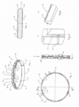
- the figures show a support body 10 with a wall 11 of ring-shaped or hollow-cylindrical geometry that surrounds a receiving opening 13 to accommodate a blank 12, which in particular consists of ceramic and possesses a disk-shaped or hollow-cylindrical geometry, as is shown in Fig. 4 .
- the support body 10 surrounds the blank 12 circumferentially, i.e. the inner geometry of the support body 10 should match the circumferential geometry of the blank 12, if necessary with a required undersize of the blank 12.
- the support body 10 is required to be able to process the blank 12, which for example may be a zirconium oxide blank, in a processing machine such as a milling machine, to produce for example a dental restoration.
- the blank 12 which for example may be a zirconium oxide blank
- a processing machine such as a milling machine
- the blank 12 is fixed in position within the support body 10 by means of an adhesive agent, in particular a UV curing adhesive.
- an adhesive agent in particular a UV curing adhesive.
- Capillary action draws the adhesive into the gap between the blank 12 and the support body 10.
- introducing the adhesive into the gap is not problem-free.
- the invention's teaching provides for a pattern of pocket-shaped depressions in the inner circumferential surface 14, i.e. the wall 11 of the support body 10, which as an example are marked with the reference labels 18, 20, 22, 24.
- the pocket-shaped depressions 18, 20, 22, 24, which hereinafter will be referred to as pockets originate directly at the respective edge, i.e.
- the pockets 18, 20, 22, 24 possess first surfaces 30, 32, 34, 36 that extend along the inner circumferential surface 16 and obliquely thereto, which results in a ramp-shaped geometry.
- the angle between the respective first surfaces 30, 32, 34, 36 and the inner circumferential surface 14 may be between 20° and 30°, and in particular may be 25°.
- the first surfaces 30, 32, 34, 36 are bordered by lateral surfaces - two of which have been marked with the reference labels 38, 40 as an example -, which with the first surfaces 30, 32, 34, 36 enclose an obtuse angle, as is illustrated in the top view of Fig. 2 .
- the support body 10 not only exhibits a trapezoid geometry in a top sectional view but also in a front view, i.e. in a view from the interior of the support body 10 in the direction towards the inner circumferential surface 14, as is shown in Fig. 3 .
- the first surface 30, 32, 34, 36 possesses a trapezoidal shape.
- FIG. 1 The perspective representation of Fig. 1 further illustrates that the pockets 18, 20 originating from the upper edge 26 are offset in such a way from the pockets 22, 24 originating from the lower edge 28 that the pockets originating form one edge are situated in the spaces between the pockets originating from the other edge and vice versa.
- the pockets 18, 20, 22, 24 are arranged in a way so that after a rotation of the arrangement 10, the pockets that have moved to the top have assumed the exact same positions relative to a reference mark, which in the embodiment example is embodied in form of a longitudinal groove 42, so that filling of adhesive material can always take place at the same positions and thus can easily be automated.
- FIG. 5 A corresponding ridge is labelled with the reference label 44 as an example ( Fig. 5 ).
- This ridge 44 which extends in parallel to the longitudinal axis of the support body 10, protrudes into the interior of the support body 10 to such an extent that a blank 12 accommodated in the support body 10 is positioned relative to the inner surface 14 in a way so that one obtains a gap width between the blank 12 and the support body 10 that is constant along the entire circumference.
- the distance A1 between consecutive pockets 18, 20, 22, 24 should be greater than that. This distance is labelled A1 in Fig. 2 .
- the distance A1 between successive depressions 18, 20, 22, 24, i.e. in the area of the lowest wall thickness, with respect to the length A2 of the respective depression along the circumferential direction should obey A2 ⁇ A1 ⁇ 2A2.
- the wall thickness D2 can for example be 1.5 mm to 5.0 mm, in particular 2.5 mm and the wall thickness in the pocket 18, 20, 22, 24 entrance area can be for example 0.5 mm to 0.9 mm, in particular 0.7 mm.
- the height of the holding bracket 10 may for example be between 5 mm and 30 mm, in particular in dependence of the height of the blank to be accommodated, which preferably possesses an extent of its height that is greater than that of the support body 10, i.e. its circular outer surfaces 44, 46 project beyond the edges 26, 28.
- the inner diameter of the holding bracket 10 may for example be 94 mm to 100 m, to provide some exemplary figures.
- a preferably circumferential ridge 43 ( Fig. 1, 5 ), which prevents the adhesive agent flowing through the gap between the blank 12 and the support body 10 from dripping out on the opposite side. Rather, the corresponding ridge 43 in this respect acts as a baffle. Other geometries for the retention of the adhesive agent are of course also possible.
- the ridge 43 is forming a structure.
- Feasible materials for the support body 10 are in particularly fiber reinforced such as glass fiber reinforced plastics such as thermoplastics, whereby the thermal expansion coefficient WAK H of the material of the support body 10 should be matched to the thermal expansion coefficient WAK R of the blank 12; in particular the WAKs should differ no more than 20 %, preferably no more than 10 %.
- the fiber content, such as glass fiber content, of the plastic, such as thermoplastic should be between 30 % by volume and 70 % by volume, in particular approximately 50% by volume.
- the support body 10 consists of polyarylamide with a glass fiber content of 30 % by volume to 70 % by volume, in particular 50 % by volume.
Landscapes
- Health & Medical Sciences (AREA)
- Veterinary Medicine (AREA)
- Epidemiology (AREA)
- Life Sciences & Earth Sciences (AREA)
- Animal Behavior & Ethology (AREA)
- General Health & Medical Sciences (AREA)
- Public Health (AREA)
- Oral & Maxillofacial Surgery (AREA)
- Dentistry (AREA)
- Engineering & Computer Science (AREA)
- Chemical & Material Sciences (AREA)
- Mechanical Engineering (AREA)
- Ceramic Engineering (AREA)
- Details Of Rigid Or Semi-Rigid Containers (AREA)
- Dental Prosthetics (AREA)
- Making Paper Articles (AREA)
- Sampling And Sample Adjustment (AREA)
- Dental Preparations (AREA)
- Packaging For Recording Disks (AREA)
Claims (13)
- Corps de support (10) et ébauche (12), en particulier une ébauche constituée de céramique telle que de l'oxyde de zirconium ou une vitrocéramique, ledit corps de support comprend une ouverture de réception (13) pour l'ébauche, l'ouverture de réception (13) étant entourée par une surface circonférentielle intérieure (14), ladite surface est bordée par un bord supérieur et un bord inférieur (26, 28), ladite ébauche est fixée en position à l'intérieur du corps de support au moyen d'un agent adhésif, dans lequel le corps de support possède une géométrie cylindrique creuse et entoure circonférentiellement l'ébauche,
dans lequel la surface circonférentielle intérieure (14) possède une structure sous la forme de plusieurs dépressions (18, 20, 22, 24) qui s'étendent jusqu'à au moins l'un des bords supérieur et inférieur (26, 28) et éventuellement au moins une élévation pour s'adapter à l'agent adhésif ; dans lequel la paroi est bordée par la surface circonférentielle intérieure (14), dans lequel les dépressions s'étendent jusqu'à au moins l'un des bords supérieur et inférieur (26, 28). - Corps de support et ébauche selon la revendication 1, caractérisés en ce que de la zone côté réception des bords supérieur et inférieur (26, 28) partent les dépressions (18, 20, 22, 24), qui se terminent de préférence à une certaine distance du centre de la surface circonférentielle intérieure, par rapport à la hauteur de ce dernier.
- Corps de support et ébauche selon au moins l'une des revendications 1 et 2, caractérisés en ce que
les dépressions (18, 20, 22, 24) sont bordées par une première surface (30, 32, 34, 36) s'étendant le long de la surface circonférentielle intérieure (14) et des surfaces latérales (38, 40) s'étendant perpendiculairement à celle-ci, et en ce que la distance entre la première surface et l'axe central du corps de support (10) diminue à partir d'un bord (26) le long de la direction vers le bord opposé (28). - Corps de support et ébauche selon au moins l'une des revendications 1 à 3, caractérisés en ce que
les dépressions (18, 20, 22, 24) sont uniformément réparties le long de la circonférence intérieure du corps de support. - Corps de support et ébauche selon au moins l'une des revendications 1 à 4, caractérisés en ce que
les dépressions (18, 20) partant d'un bord (26) présenteront les mêmes distances par rapport à un repère (42) du corps de support que les dépressions (22, 24) partant de l'autre bord (28) après une rotation du corps de support (10) de 180° autour de son axe transversal. - Corps de support et ébauche selon au moins l'une des revendications 1 à 5, caractérisés en ce que
la structure comprend en outre au moins une élévation telle qu'une crête (43) et/ou une dépression qui s'étend à une certaine distance du bord (26, 28) et part de la surface circonférentielle intérieure (14) de la paroi (11), moyennant quoi, de préférence, l'élévation et/ou la dépression s'étendant à une certaine distance du bord est prévue en plus desdites multiples dépressions (18, 20, 22, 24). - Corps de support et ébauche selon au moins l'une des revendications 1 à 6, caractérisés en ce que
de la surface circonférentielle intérieure (14), partent une ou plusieurs saillies, telles que des nervures (44), qui s'étendent au moins par sections au-dessus de la hauteur de la surface circonférentielle intérieure et servent de support à l'ébauche (12). - Corps de support et ébauche selon la revendication 3, caractérisés en ce que
la première surface (30, 32, 34, 36) des dépressions (18, 20, 22, 24) forme avec la surface circonférentielle intérieure (14) un angle α avec 20°≤ α ≤ 30°, en particulier α = 25°. - Corps de support et ébauche selon au moins l'une des revendications 1 à 8, caractérisés en ce que
dans la zone centrale de la surface circonférentielle intérieure (14) s'étend une nervure ou dépression de préférence circonférentielle, telle qu'une rainure, qui s'étend en particulier parallèlement aux bords (26, 28). - Corps de support et ébauche selon au moins l'une des revendications 1 à 9, caractérisés en ce que
dans la zone des dépressions (18, 20, 22, 24), la paroi (11) du corps de support (10) possède, dans la zone des bords, une épaisseur D1 et, à l'extérieur des dépressions, possède une épaisseur D2, moyennant quoi 8*D1 ≥ D2 ≥ 2:2*D1. - Corps de support et ébauche selon au moins l'une des revendications 1 à 10, caractérisés en ce que
la distance A1 entre des dépressions (18, 20, 22, 24) successives par rapport à la longueur A2 de la dépression respective le long de la direction circonférentielle obéit à A2 ≤ A1 ≤ 2*A2. - Corps de support et ébauche selon au moins l'une des revendications 1 à 11, caractérisés en ce que
le corps de support (10) est en matière plastique, en particulier en matière plastique renforcée de fibres, telle qu'une matière plastique renforcée de fibres de verre, telle qu'une matière thermoplastique, moyennant quoi, en particulier, le coefficient de dilatation thermique WAKH du matériau est adapté en particulier au coefficient de dilatation thermique WAKR de l'ébauche et, en particulier, les coefficients de dilatation thermique ne diffèrent pas de plus de 20 %, de préférence de pas plus de 10 %. - Corps de support et ébauche selon au moins l'une des revendications 1 à 12, caractérisés en ce que
la teneur en fibres, telle que la teneur en fibres de verre, du corps de support (10) est comprise entre 30 % en volume et 70 % en volume, en particulier environ 50 % en volume.
Priority Applications (1)
| Application Number | Priority Date | Filing Date | Title |
|---|---|---|---|
| PCT/EP2016/053431 WO2016116636A1 (fr) | 2015-01-19 | 2016-02-18 | Corps de support pour découpe |
Applications Claiming Priority (1)
| Application Number | Priority Date | Filing Date | Title |
|---|---|---|---|
| DE102015100666.9A DE102015100666A1 (de) | 2015-01-19 | 2015-01-19 | Halterung für einen Rohling |
Publications (3)
| Publication Number | Publication Date |
|---|---|
| EP3045145A2 EP3045145A2 (fr) | 2016-07-20 |
| EP3045145A3 EP3045145A3 (fr) | 2016-07-27 |
| EP3045145B1 true EP3045145B1 (fr) | 2023-05-10 |
Family
ID=55182228
Family Applications (1)
| Application Number | Title | Priority Date | Filing Date |
|---|---|---|---|
| EP16151778.4A Active EP3045145B1 (fr) | 2015-01-19 | 2016-01-19 | Corps de support pour une ébauche et ébauche |
Country Status (5)
| Country | Link |
|---|---|
| US (2) | US10327874B2 (fr) |
| EP (1) | EP3045145B1 (fr) |
| DE (1) | DE102015100666A1 (fr) |
| ES (1) | ES2951705T3 (fr) |
| WO (1) | WO2016116636A1 (fr) |
Families Citing this family (9)
| Publication number | Priority date | Publication date | Assignee | Title |
|---|---|---|---|---|
| DE102015100666A1 (de) | 2015-01-19 | 2016-07-21 | Dentsply International Inc. | Halterung für einen Rohling |
| DE102015204174A1 (de) * | 2015-03-09 | 2016-09-15 | Precis Glashütte GmbH | Haltevorrichtung für Dentalrohlinge |
| WO2016148287A1 (fr) * | 2015-03-19 | 2016-09-22 | クラレノリタケデンタル株式会社 | Unité à façonner, et procédé de fabrication de celle-ci |
| US10905532B2 (en) * | 2016-08-26 | 2021-02-02 | Shofu Inc. | Mill blank for dental CAD/CAM with resin portion contacted with CAM device |
| USD837271S1 (en) * | 2016-12-23 | 2019-01-01 | Ivoclar Vivadent Ag | Milling machine |
| ES2918185T3 (es) | 2018-12-20 | 2022-07-14 | Ivoclar Vivadent Ag | Bloque de molienda dental multicolor |
| KR102432438B1 (ko) * | 2020-08-21 | 2022-08-16 | 주식회사 하스 | 치과용 블랭크 |
| ES3006507T3 (en) * | 2022-03-08 | 2025-03-18 | Ivoclar Vivadent Ag | Holding device for a dental blank |
| CN116175104A (zh) * | 2023-04-04 | 2023-05-30 | 成都瑞雪丰泰精密电子股份有限公司 | 一种薄壁易变形类工件的加工方法 |
Citations (1)
| Publication number | Priority date | Publication date | Assignee | Title |
|---|---|---|---|---|
| US20130244846A1 (en) * | 2011-08-10 | 2013-09-19 | Armann Girrbach Ag | Clamping device |
Family Cites Families (39)
| Publication number | Priority date | Publication date | Assignee | Title |
|---|---|---|---|---|
| US3276122A (en) * | 1964-01-03 | 1966-10-04 | Williams Gold Refining Co | Positioning device |
| US3601895A (en) * | 1970-01-27 | 1971-08-31 | Frank L Zollner | Method of making a dental crown with gold apron |
| US3762032A (en) * | 1971-08-19 | 1973-10-02 | Gen Motors Corp | Bonding |
| US4644639A (en) * | 1984-12-21 | 1987-02-24 | At&T Technologies, Inc. | Method of supporting an article |
| WO1995030382A1 (fr) * | 1994-05-05 | 1995-11-16 | Joseph Hintersehr | Procede et dispositif de fabrication d'une prothese dentaire |
| US5791035A (en) * | 1995-09-13 | 1998-08-11 | Nok Corporation | Method for making a sensor element |
| US5813859A (en) * | 1997-01-23 | 1998-09-29 | Hajjar; Victor J. | Method and apparatus for tooth restoration |
| US6267655B1 (en) * | 1998-07-15 | 2001-07-31 | Mosel Vitelic, Inc. | Retaining ring for wafer polishing |
| DE29815486U1 (de) | 1998-08-28 | 2000-01-05 | ESPE Dental AG, 82229 Seefeld | Vorrichtung zur Herstellung eines Zahnersatzteils |
| EP1087720B1 (fr) | 1999-04-16 | 2004-04-07 | Kaltenbach & Voigt GmbH & Co. KG | Procede de production d'elements ceramique medicaux, medico-dentaires, prothetiques dentaires et techniques |
| ATE430530T1 (de) | 2000-12-07 | 2009-05-15 | Eidgenoess Tech Hochschule | Haltevorrichtung für einen keramikrohling |
| WO2002047573A1 (fr) * | 2000-12-12 | 2002-06-20 | Eidgenössische Technische Hochschule Zürich Nichtmetallische Werkstoffe | Dispositif de maintien pour modele de prothese dentaire ou de structure de base |
| DE20105248U1 (de) * | 2001-03-26 | 2002-08-01 | Kaltenbach & Voigt | Fräs-/Schleifmaschine zur Herstellung von zahnmedizinischen Werkstücken |
| SE522125C2 (sv) | 2001-05-22 | 2004-01-13 | Sandvik Ab | Gängverktyg med ringformig kam |
| DE202004021805U1 (de) * | 2003-04-04 | 2011-03-17 | Xawex Ag | Rohling für die Herstellung von zahnmedizinischen Rekonstruktionen |
| DE10330758B4 (de) * | 2003-07-07 | 2006-07-20 | Sirona Dental Systems Gmbh | Rohling zur Herstellung zahntechnischer Formteile und Verfahren zur Herstellung des Formteils |
| DE102005008004A1 (de) * | 2004-04-22 | 2005-11-24 | Brinkmann, Johannes, Dipl.-Ing. | Verfahren zum Bearbeiten von wenigstens einem Werkstück sowie Vorrichtung zur Durchführung des Verfahrens |
| US7789601B2 (en) * | 2004-06-14 | 2010-09-07 | D4D Technologies, Llc | Mill blank mandrel |
| ES2321430T3 (es) * | 2004-11-25 | 2009-06-05 | Heinrich Steger | Instalacion fresadora-copiadora para la produccion de piezas de trabajo especialmente de tecnica dental. |
| DE102005023106A1 (de) * | 2005-05-13 | 2006-11-16 | Sirona Dental Systems Gmbh | Verfahren zur Herstellung eines Zahnersatzteils, Zahnersatzteil, Bauteil und Rohling hierzu |
| DE102006027397A1 (de) | 2006-06-13 | 2007-12-20 | Amann Girrbach Gmbh | Werkstück zum Bearbeiten in spanabhebenden Bearbeitungsvorrichtungen |
| DE102007013675B4 (de) | 2007-03-19 | 2011-01-13 | Doceram Gmbh | Halterung für keramische Rohlinge |
| US8551622B2 (en) * | 2007-07-20 | 2013-10-08 | Ivoclar Vivadent Ag | Addressable matrices/cluster blanks for dental CAD/CAM systems and optimization thereof |
| AT506486B1 (de) * | 2008-02-15 | 2013-03-15 | Steger Heinrich | Aufspannvorrichtung für eine rechnergesteuerte, spanabhebende bearbeitungsmaschine |
| KR100856019B1 (ko) * | 2008-02-22 | 2008-09-02 | (주)타이닉스 | 플라즈마 처리장치의 기판 홀더 |
| US20090274994A1 (en) * | 2009-04-28 | 2009-11-05 | Yunoh Jung | Device and Method of Securing Dental Material for Production of Dental Prosthesis |
| DE102009023122A1 (de) * | 2009-05-22 | 2010-11-25 | Gebr. Schmid Gmbh & Co. | Träger für einen Siliziumblock sowie Herstellungsverfahren eines solchen Trägers |
| DE202010001125U1 (de) | 2010-01-22 | 2010-04-08 | Heimatec Gmbh | Vorrichtung zum Halten von zur Herstellung von Zahnersatzteilen dienenden Rohlingen |
| JP2013525131A (ja) * | 2010-04-29 | 2013-06-20 | デンタル ラボラトリー マイリング サプライズ エルエルシー | ブランクからの製品製造方法、システム、および装置 |
| DE102011101678A1 (de) * | 2011-05-16 | 2012-11-22 | Amann Girrbach Ag | Prothesenzahnträger |
| DE102012201744A1 (de) | 2012-02-06 | 2013-08-08 | Wieland Dental + Technik Gmbh & Co. Kg | Werkstücksystem |
| DE202012008015U1 (de) | 2012-08-23 | 2012-12-12 | Doceram Gmbh | Halter für Rohlinge |
| DE102012215906A1 (de) * | 2012-09-07 | 2014-03-13 | Robert Bosch Gmbh | Elektromotor und Verfahren zur Herstellung eines Elektromotors |
| KR101325478B1 (ko) * | 2013-06-10 | 2013-11-07 | 문교산업 주식회사 | 치과용 석고블록 |
| WO2014200226A1 (fr) * | 2013-06-10 | 2014-12-18 | 문교산업 주식회사 | Bloc de plâtre dentaire et son procédé de fabrication |
| DE202013103515U1 (de) | 2013-08-05 | 2013-09-12 | Ivoclar Vivadent Ag | Rohlingaufnahme sowie Dental-Fräsmaschine |
| DE102015100666A1 (de) | 2015-01-19 | 2016-07-21 | Dentsply International Inc. | Halterung für einen Rohling |
| AT516263B1 (de) * | 2015-01-21 | 2016-04-15 | Steger Heinrich | Haltevorrichtung für ein dentales Werkstück |
| DE102015204174A1 (de) * | 2015-03-09 | 2016-09-15 | Precis Glashütte GmbH | Haltevorrichtung für Dentalrohlinge |
-
2015
- 2015-01-19 DE DE102015100666.9A patent/DE102015100666A1/de not_active Withdrawn
-
2016
- 2016-01-19 EP EP16151778.4A patent/EP3045145B1/fr active Active
- 2016-01-19 US US15/000,385 patent/US10327874B2/en active Active
- 2016-01-19 ES ES16151778T patent/ES2951705T3/es active Active
- 2016-02-18 WO PCT/EP2016/053431 patent/WO2016116636A1/fr not_active Ceased
-
2019
- 2019-05-10 US US16/408,626 patent/US11166794B2/en active Active
Patent Citations (1)
| Publication number | Priority date | Publication date | Assignee | Title |
|---|---|---|---|---|
| US20130244846A1 (en) * | 2011-08-10 | 2013-09-19 | Armann Girrbach Ag | Clamping device |
Also Published As
| Publication number | Publication date |
|---|---|
| EP3045145A2 (fr) | 2016-07-20 |
| US20160206411A1 (en) | 2016-07-21 |
| EP3045145A3 (fr) | 2016-07-27 |
| ES2951705T3 (es) | 2023-10-24 |
| WO2016116636A8 (fr) | 2016-11-10 |
| WO2016116636A1 (fr) | 2016-07-28 |
| US11166794B2 (en) | 2021-11-09 |
| US10327874B2 (en) | 2019-06-25 |
| US20190274798A1 (en) | 2019-09-12 |
| DE102015100666A1 (de) | 2016-07-21 |
Similar Documents
| Publication | Publication Date | Title |
|---|---|---|
| EP3045145B1 (fr) | Corps de support pour une ébauche et ébauche | |
| US8739409B2 (en) | Method for dual production of small-scale products | |
| CN100553956C (zh) | 采用圆坯制造镜片的方法 | |
| JP3947465B2 (ja) | 歯科用ワークピースを製造するための装置 | |
| CN102099141B (zh) | 可分度的切削镶片 | |
| JP5661613B2 (ja) | 切屑除去工具 | |
| DE60216323D1 (de) | Maschine zur durchführung von bearbeitungsvorgängen an einem werkstück und verfahren zur steuerung derselben | |
| EP2440351B1 (fr) | Outil de coupe et plaquette de coupe correspondante | |
| DE60113593D1 (de) | Numerisch gesteuerte Werkzeugmaschine mit System zur Erkennung der Radialabweichung der Spindel | |
| JP2010532274A (ja) | マルチピース工具組立体及び切削工具 | |
| KR101714476B1 (ko) | 소프트 조 가공유닛 | |
| DE60111126D1 (de) | Verfahren zur Bearbeitung von Werkstücken mit einem komplexen Werkzeug | |
| MXPA01013351A (es) | Mandril de sujecion para sujetar herramientas mediante ajuste por contraccion. | |
| ES2771255T3 (es) | Preforma de prótesis para la producción de un cuerpo de prótesis dental | |
| ATE326916T1 (de) | Vorrichtung und verfahren zur erstellung von zahnmedizinischen passkörpern | |
| CN101678464A (zh) | 用于分型和倒角的嵌件 | |
| EP3513765A1 (fr) | Dispositif de fixation d'une pièce de travail | |
| KR102011944B1 (ko) | 3d 프린터 제조형 임플란트 가공용 선반기의 콜렉트 척 | |
| US20160278893A1 (en) | Method and device for securing prefabricated prosthetic teeth | |
| JP2022554124A (ja) | 凹部を有する切削工具の製造方法 | |
| US20060264159A1 (en) | Lens production method and process | |
| US20200009659A1 (en) | Method and Device for Machining a Workpiece | |
| CN110899744B (zh) | 一种数控机床上用于带锥孔工件的加工夹具 | |
| US20070200275A1 (en) | Process for obtaining a diamond tool, particularly for cutting stone materials and the like | |
| WO2011103116A2 (fr) | Élément de liaison pour constituer une interface entre deux pièces d'une machine-outil qu'on peut relier l'une à l'autre de façon réversible et procédé de fabrication d'un tel élément de liaison |
Legal Events
| Date | Code | Title | Description |
|---|---|---|---|
| PUAI | Public reference made under article 153(3) epc to a published international application that has entered the european phase |
Free format text: ORIGINAL CODE: 0009012 |
|
| PUAL | Search report despatched |
Free format text: ORIGINAL CODE: 0009013 |
|
| AK | Designated contracting states |
Kind code of ref document: A2 Designated state(s): AL AT BE BG CH CY CZ DE DK EE ES FI FR GB GR HR HU IE IS IT LI LT LU LV MC MK MT NL NO PL PT RO RS SE SI SK SM TR |
|
| AX | Request for extension of the european patent |
Extension state: BA ME |
|
| AK | Designated contracting states |
Kind code of ref document: A3 Designated state(s): AL AT BE BG CH CY CZ DE DK EE ES FI FR GB GR HR HU IE IS IT LI LT LU LV MC MK MT NL NO PL PT RO RS SE SI SK SM TR |
|
| AX | Request for extension of the european patent |
Extension state: BA ME |
|
| RIC1 | Information provided on ipc code assigned before grant |
Ipc: A61C 13/00 20060101AFI20160623BHEP |
|
| STAA | Information on the status of an ep patent application or granted ep patent |
Free format text: STATUS: REQUEST FOR EXAMINATION WAS MADE |
|
| 17P | Request for examination filed |
Effective date: 20170117 |
|
| RBV | Designated contracting states (corrected) |
Designated state(s): AL AT BE BG CH CY CZ DE DK EE ES FI FR GB GR HR HU IE IS IT LI LT LU LV MC MK MT NL NO PL PT RO RS SE SI SK SM TR |
|
| RAP1 | Party data changed (applicant data changed or rights of an application transferred) |
Owner name: DENTSPLY SIRONA INC. |
|
| STAA | Information on the status of an ep patent application or granted ep patent |
Free format text: STATUS: EXAMINATION IS IN PROGRESS |
|
| 17Q | First examination report despatched |
Effective date: 20180515 |
|
| GRAP | Despatch of communication of intention to grant a patent |
Free format text: ORIGINAL CODE: EPIDOSNIGR1 |
|
| STAA | Information on the status of an ep patent application or granted ep patent |
Free format text: STATUS: GRANT OF PATENT IS INTENDED |
|
| INTG | Intention to grant announced |
Effective date: 20221206 |
|
| RIN1 | Information on inventor provided before grant (corrected) |
Inventor name: VOELKL, LOTHAR Inventor name: FECHER, STEFAN Inventor name: KUTZNER, MARTIN |
|
| GRAS | Grant fee paid |
Free format text: ORIGINAL CODE: EPIDOSNIGR3 |
|
| GRAA | (expected) grant |
Free format text: ORIGINAL CODE: 0009210 |
|
| STAA | Information on the status of an ep patent application or granted ep patent |
Free format text: STATUS: THE PATENT HAS BEEN GRANTED |
|
| AK | Designated contracting states |
Kind code of ref document: B1 Designated state(s): AL AT BE BG CH CY CZ DE DK EE ES FI FR GB GR HR HU IE IS IT LI LT LU LV MC MK MT NL NO PL PT RO RS SE SI SK SM TR |
|
| REG | Reference to a national code |
Ref country code: GB Ref legal event code: FG4D |
|
| REG | Reference to a national code |
Ref country code: AT Ref legal event code: REF Ref document number: 1565992 Country of ref document: AT Kind code of ref document: T Effective date: 20230515 Ref country code: CH Ref legal event code: EP |
|
| REG | Reference to a national code |
Ref country code: DE Ref legal event code: R096 Ref document number: 602016079281 Country of ref document: DE |
|
| REG | Reference to a national code |
Ref country code: IE Ref legal event code: FG4D |
|
| P01 | Opt-out of the competence of the unified patent court (upc) registered |
Effective date: 20230619 |
|
| REG | Reference to a national code |
Ref country code: NL Ref legal event code: FP |
|
| REG | Reference to a national code |
Ref country code: SE Ref legal event code: TRGR |
|
| REG | Reference to a national code |
Ref country code: LT Ref legal event code: MG9D |
|
| REG | Reference to a national code |
Ref country code: ES Ref legal event code: FG2A Ref document number: 2951705 Country of ref document: ES Kind code of ref document: T3 Effective date: 20231024 |
|
| PG25 | Lapsed in a contracting state [announced via postgrant information from national office to epo] |
Ref country code: PT Free format text: LAPSE BECAUSE OF FAILURE TO SUBMIT A TRANSLATION OF THE DESCRIPTION OR TO PAY THE FEE WITHIN THE PRESCRIBED TIME-LIMIT Effective date: 20230911 Ref country code: NO Free format text: LAPSE BECAUSE OF FAILURE TO SUBMIT A TRANSLATION OF THE DESCRIPTION OR TO PAY THE FEE WITHIN THE PRESCRIBED TIME-LIMIT Effective date: 20230810 |
|
| PG25 | Lapsed in a contracting state [announced via postgrant information from national office to epo] |
Ref country code: RS Free format text: LAPSE BECAUSE OF FAILURE TO SUBMIT A TRANSLATION OF THE DESCRIPTION OR TO PAY THE FEE WITHIN THE PRESCRIBED TIME-LIMIT Effective date: 20230510 Ref country code: PL Free format text: LAPSE BECAUSE OF FAILURE TO SUBMIT A TRANSLATION OF THE DESCRIPTION OR TO PAY THE FEE WITHIN THE PRESCRIBED TIME-LIMIT Effective date: 20230510 Ref country code: LV Free format text: LAPSE BECAUSE OF FAILURE TO SUBMIT A TRANSLATION OF THE DESCRIPTION OR TO PAY THE FEE WITHIN THE PRESCRIBED TIME-LIMIT Effective date: 20230510 Ref country code: LT Free format text: LAPSE BECAUSE OF FAILURE TO SUBMIT A TRANSLATION OF THE DESCRIPTION OR TO PAY THE FEE WITHIN THE PRESCRIBED TIME-LIMIT Effective date: 20230510 Ref country code: IS Free format text: LAPSE BECAUSE OF FAILURE TO SUBMIT A TRANSLATION OF THE DESCRIPTION OR TO PAY THE FEE WITHIN THE PRESCRIBED TIME-LIMIT Effective date: 20230910 Ref country code: HR Free format text: LAPSE BECAUSE OF FAILURE TO SUBMIT A TRANSLATION OF THE DESCRIPTION OR TO PAY THE FEE WITHIN THE PRESCRIBED TIME-LIMIT Effective date: 20230510 Ref country code: GR Free format text: LAPSE BECAUSE OF FAILURE TO SUBMIT A TRANSLATION OF THE DESCRIPTION OR TO PAY THE FEE WITHIN THE PRESCRIBED TIME-LIMIT Effective date: 20230811 |
|
| PG25 | Lapsed in a contracting state [announced via postgrant information from national office to epo] |
Ref country code: FI Free format text: LAPSE BECAUSE OF FAILURE TO SUBMIT A TRANSLATION OF THE DESCRIPTION OR TO PAY THE FEE WITHIN THE PRESCRIBED TIME-LIMIT Effective date: 20230510 |
|
| PG25 | Lapsed in a contracting state [announced via postgrant information from national office to epo] |
Ref country code: SK Free format text: LAPSE BECAUSE OF FAILURE TO SUBMIT A TRANSLATION OF THE DESCRIPTION OR TO PAY THE FEE WITHIN THE PRESCRIBED TIME-LIMIT Effective date: 20230510 |
|
| PG25 | Lapsed in a contracting state [announced via postgrant information from national office to epo] |
Ref country code: SM Free format text: LAPSE BECAUSE OF FAILURE TO SUBMIT A TRANSLATION OF THE DESCRIPTION OR TO PAY THE FEE WITHIN THE PRESCRIBED TIME-LIMIT Effective date: 20230510 Ref country code: SK Free format text: LAPSE BECAUSE OF FAILURE TO SUBMIT A TRANSLATION OF THE DESCRIPTION OR TO PAY THE FEE WITHIN THE PRESCRIBED TIME-LIMIT Effective date: 20230510 Ref country code: RO Free format text: LAPSE BECAUSE OF FAILURE TO SUBMIT A TRANSLATION OF THE DESCRIPTION OR TO PAY THE FEE WITHIN THE PRESCRIBED TIME-LIMIT Effective date: 20230510 Ref country code: EE Free format text: LAPSE BECAUSE OF FAILURE TO SUBMIT A TRANSLATION OF THE DESCRIPTION OR TO PAY THE FEE WITHIN THE PRESCRIBED TIME-LIMIT Effective date: 20230510 Ref country code: DK Free format text: LAPSE BECAUSE OF FAILURE TO SUBMIT A TRANSLATION OF THE DESCRIPTION OR TO PAY THE FEE WITHIN THE PRESCRIBED TIME-LIMIT Effective date: 20230510 Ref country code: CZ Free format text: LAPSE BECAUSE OF FAILURE TO SUBMIT A TRANSLATION OF THE DESCRIPTION OR TO PAY THE FEE WITHIN THE PRESCRIBED TIME-LIMIT Effective date: 20230510 |
|
| REG | Reference to a national code |
Ref country code: DE Ref legal event code: R097 Ref document number: 602016079281 Country of ref document: DE |
|
| REG | Reference to a national code |
Ref country code: AT Ref legal event code: UEP Ref document number: 1565992 Country of ref document: AT Kind code of ref document: T Effective date: 20230510 |
|
| PLBE | No opposition filed within time limit |
Free format text: ORIGINAL CODE: 0009261 |
|
| STAA | Information on the status of an ep patent application or granted ep patent |
Free format text: STATUS: NO OPPOSITION FILED WITHIN TIME LIMIT |
|
| 26N | No opposition filed |
Effective date: 20240213 |
|
| PGFP | Annual fee paid to national office [announced via postgrant information from national office to epo] |
Ref country code: AT Payment date: 20231227 Year of fee payment: 9 |
|
| PG25 | Lapsed in a contracting state [announced via postgrant information from national office to epo] |
Ref country code: SI Free format text: LAPSE BECAUSE OF FAILURE TO SUBMIT A TRANSLATION OF THE DESCRIPTION OR TO PAY THE FEE WITHIN THE PRESCRIBED TIME-LIMIT Effective date: 20230510 |
|
| PG25 | Lapsed in a contracting state [announced via postgrant information from national office to epo] |
Ref country code: SI Free format text: LAPSE BECAUSE OF FAILURE TO SUBMIT A TRANSLATION OF THE DESCRIPTION OR TO PAY THE FEE WITHIN THE PRESCRIBED TIME-LIMIT Effective date: 20230510 |
|
| PG25 | Lapsed in a contracting state [announced via postgrant information from national office to epo] |
Ref country code: MC Free format text: LAPSE BECAUSE OF FAILURE TO SUBMIT A TRANSLATION OF THE DESCRIPTION OR TO PAY THE FEE WITHIN THE PRESCRIBED TIME-LIMIT Effective date: 20230510 |
|
| PG25 | Lapsed in a contracting state [announced via postgrant information from national office to epo] |
Ref country code: MC Free format text: LAPSE BECAUSE OF FAILURE TO SUBMIT A TRANSLATION OF THE DESCRIPTION OR TO PAY THE FEE WITHIN THE PRESCRIBED TIME-LIMIT Effective date: 20230510 |
|
| PG25 | Lapsed in a contracting state [announced via postgrant information from national office to epo] |
Ref country code: LU Free format text: LAPSE BECAUSE OF NON-PAYMENT OF DUE FEES Effective date: 20240119 |
|
| PG25 | Lapsed in a contracting state [announced via postgrant information from national office to epo] |
Ref country code: LU Free format text: LAPSE BECAUSE OF NON-PAYMENT OF DUE FEES Effective date: 20240119 |
|
| PG25 | Lapsed in a contracting state [announced via postgrant information from national office to epo] |
Ref country code: BE Free format text: LAPSE BECAUSE OF NON-PAYMENT OF DUE FEES Effective date: 20240131 |
|
| PG25 | Lapsed in a contracting state [announced via postgrant information from national office to epo] |
Ref country code: BE Free format text: LAPSE BECAUSE OF NON-PAYMENT OF DUE FEES Effective date: 20240131 |
|
| REG | Reference to a national code |
Ref country code: BE Ref legal event code: MM Effective date: 20240131 |
|
| PG25 | Lapsed in a contracting state [announced via postgrant information from national office to epo] |
Ref country code: BG Free format text: LAPSE BECAUSE OF FAILURE TO SUBMIT A TRANSLATION OF THE DESCRIPTION OR TO PAY THE FEE WITHIN THE PRESCRIBED TIME-LIMIT Effective date: 20230510 |
|
| PG25 | Lapsed in a contracting state [announced via postgrant information from national office to epo] |
Ref country code: BG Free format text: LAPSE BECAUSE OF FAILURE TO SUBMIT A TRANSLATION OF THE DESCRIPTION OR TO PAY THE FEE WITHIN THE PRESCRIBED TIME-LIMIT Effective date: 20230510 |
|
| PGFP | Annual fee paid to national office [announced via postgrant information from national office to epo] |
Ref country code: NL Payment date: 20241214 Year of fee payment: 10 |
|
| PG25 | Lapsed in a contracting state [announced via postgrant information from national office to epo] |
Ref country code: IE Free format text: LAPSE BECAUSE OF NON-PAYMENT OF DUE FEES Effective date: 20240119 |
|
| PGFP | Annual fee paid to national office [announced via postgrant information from national office to epo] |
Ref country code: SE Payment date: 20241212 Year of fee payment: 10 |
|
| PG25 | Lapsed in a contracting state [announced via postgrant information from national office to epo] |
Ref country code: IE Free format text: LAPSE BECAUSE OF NON-PAYMENT OF DUE FEES Effective date: 20240119 |
|
| PGFP | Annual fee paid to national office [announced via postgrant information from national office to epo] |
Ref country code: DE Payment date: 20241203 Year of fee payment: 10 |
|
| PGFP | Annual fee paid to national office [announced via postgrant information from national office to epo] |
Ref country code: ES Payment date: 20250210 Year of fee payment: 10 |
|
| PGFP | Annual fee paid to national office [announced via postgrant information from national office to epo] |
Ref country code: CH Payment date: 20250201 Year of fee payment: 10 |
|
| PGFP | Annual fee paid to national office [announced via postgrant information from national office to epo] |
Ref country code: IT Payment date: 20241210 Year of fee payment: 10 |
|
| PG25 | Lapsed in a contracting state [announced via postgrant information from national office to epo] |
Ref country code: CY Free format text: LAPSE BECAUSE OF FAILURE TO SUBMIT A TRANSLATION OF THE DESCRIPTION OR TO PAY THE FEE WITHIN THE PRESCRIBED TIME-LIMIT; INVALID AB INITIO Effective date: 20160119 |
|
| PG25 | Lapsed in a contracting state [announced via postgrant information from national office to epo] |
Ref country code: HU Free format text: LAPSE BECAUSE OF FAILURE TO SUBMIT A TRANSLATION OF THE DESCRIPTION OR TO PAY THE FEE WITHIN THE PRESCRIBED TIME-LIMIT; INVALID AB INITIO Effective date: 20160119 |
|
| REG | Reference to a national code |
Ref country code: AT Ref legal event code: MM01 Ref document number: 1565992 Country of ref document: AT Kind code of ref document: T Effective date: 20250119 |
|
| PG25 | Lapsed in a contracting state [announced via postgrant information from national office to epo] |
Ref country code: AT Free format text: LAPSE BECAUSE OF NON-PAYMENT OF DUE FEES Effective date: 20250119 |
|
| PG25 | Lapsed in a contracting state [announced via postgrant information from national office to epo] |
Ref country code: TR Free format text: LAPSE BECAUSE OF FAILURE TO SUBMIT A TRANSLATION OF THE DESCRIPTION OR TO PAY THE FEE WITHIN THE PRESCRIBED TIME-LIMIT Effective date: 20230510 |
|
| PGFP | Annual fee paid to national office [announced via postgrant information from national office to epo] |
Ref country code: GB Payment date: 20251220 Year of fee payment: 11 |
|
| PGFP | Annual fee paid to national office [announced via postgrant information from national office to epo] |
Ref country code: FR Payment date: 20251217 Year of fee payment: 11 |