EP3044541B1 - Gyroskopstruktur und gyroskop mit verbesserter quadraturkompensation - Google Patents
Gyroskopstruktur und gyroskop mit verbesserter quadraturkompensation Download PDFInfo
- Publication number
- EP3044541B1 EP3044541B1 EP14776734.7A EP14776734A EP3044541B1 EP 3044541 B1 EP3044541 B1 EP 3044541B1 EP 14776734 A EP14776734 A EP 14776734A EP 3044541 B1 EP3044541 B1 EP 3044541B1
- Authority
- EP
- European Patent Office
- Prior art keywords
- seismic mass
- conductor
- oscillation
- plane
- microelectromechanical gyroscope
- Prior art date
- Legal status (The legal status is an assumption and is not a legal conclusion. Google has not performed a legal analysis and makes no representation as to the accuracy of the status listed.)
- Active
Links
Images



Classifications
-
- G—PHYSICS
- G01—MEASURING; TESTING
- G01C—MEASURING DISTANCES, LEVELS OR BEARINGS; SURVEYING; NAVIGATION; GYROSCOPIC INSTRUMENTS; PHOTOGRAMMETRY OR VIDEOGRAMMETRY
- G01C19/00—Gyroscopes; Turn-sensitive devices using vibrating masses; Turn-sensitive devices without moving masses; Measuring angular rate using gyroscopic effects
- G01C19/56—Turn-sensitive devices using vibrating masses, e.g. vibratory angular rate sensors based on Coriolis forces
- G01C19/5719—Turn-sensitive devices using vibrating masses, e.g. vibratory angular rate sensors based on Coriolis forces using planar vibrating masses driven in a translation vibration along an axis
- G01C19/5733—Structural details or topology
-
- B—PERFORMING OPERATIONS; TRANSPORTING
- B81—MICROSTRUCTURAL TECHNOLOGY
- B81B—MICROSTRUCTURAL DEVICES OR SYSTEMS, e.g. MICROMECHANICAL DEVICES
- B81B7/00—Microstructural systems ; Auxiliary parts of microstructural devices or systems
- B81B7/02—Microstructural systems ; Auxiliary parts of microstructural devices or systems containing distinct electrical or optical devices of particular relevance for their function, e.g. microelectro-mechanical systems [MEMS]
-
- G—PHYSICS
- G01—MEASURING; TESTING
- G01C—MEASURING DISTANCES, LEVELS OR BEARINGS; SURVEYING; NAVIGATION; GYROSCOPIC INSTRUMENTS; PHOTOGRAMMETRY OR VIDEOGRAMMETRY
- G01C19/00—Gyroscopes; Turn-sensitive devices using vibrating masses; Turn-sensitive devices without moving masses; Measuring angular rate using gyroscopic effects
- G01C19/56—Turn-sensitive devices using vibrating masses, e.g. vibratory angular rate sensors based on Coriolis forces
- G01C19/5607—Turn-sensitive devices using vibrating masses, e.g. vibratory angular rate sensors based on Coriolis forces using vibrating tuning forks
- G01C19/5621—Turn-sensitive devices using vibrating masses, e.g. vibratory angular rate sensors based on Coriolis forces using vibrating tuning forks the devices involving a micromechanical structure
-
- G—PHYSICS
- G01—MEASURING; TESTING
- G01C—MEASURING DISTANCES, LEVELS OR BEARINGS; SURVEYING; NAVIGATION; GYROSCOPIC INSTRUMENTS; PHOTOGRAMMETRY OR VIDEOGRAMMETRY
- G01C19/00—Gyroscopes; Turn-sensitive devices using vibrating masses; Turn-sensitive devices without moving masses; Measuring angular rate using gyroscopic effects
- G01C19/56—Turn-sensitive devices using vibrating masses, e.g. vibratory angular rate sensors based on Coriolis forces
- G01C19/5642—Turn-sensitive devices using vibrating masses, e.g. vibratory angular rate sensors based on Coriolis forces using vibrating bars or beams
- G01C19/5656—Turn-sensitive devices using vibrating masses, e.g. vibratory angular rate sensors based on Coriolis forces using vibrating bars or beams the devices involving a micromechanical structure
-
- G—PHYSICS
- G01—MEASURING; TESTING
- G01C—MEASURING DISTANCES, LEVELS OR BEARINGS; SURVEYING; NAVIGATION; GYROSCOPIC INSTRUMENTS; PHOTOGRAMMETRY OR VIDEOGRAMMETRY
- G01C19/00—Gyroscopes; Turn-sensitive devices using vibrating masses; Turn-sensitive devices without moving masses; Measuring angular rate using gyroscopic effects
- G01C19/56—Turn-sensitive devices using vibrating masses, e.g. vibratory angular rate sensors based on Coriolis forces
- G01C19/5705—Turn-sensitive devices using vibrating masses, e.g. vibratory angular rate sensors based on Coriolis forces using masses driven in reciprocating rotary motion about an axis
- G01C19/5712—Turn-sensitive devices using vibrating masses, e.g. vibratory angular rate sensors based on Coriolis forces using masses driven in reciprocating rotary motion about an axis the devices involving a micromechanical structure
-
- G—PHYSICS
- G01—MEASURING; TESTING
- G01C—MEASURING DISTANCES, LEVELS OR BEARINGS; SURVEYING; NAVIGATION; GYROSCOPIC INSTRUMENTS; PHOTOGRAMMETRY OR VIDEOGRAMMETRY
- G01C19/00—Gyroscopes; Turn-sensitive devices using vibrating masses; Turn-sensitive devices without moving masses; Measuring angular rate using gyroscopic effects
- G01C19/56—Turn-sensitive devices using vibrating masses, e.g. vibratory angular rate sensors based on Coriolis forces
- G01C19/5719—Turn-sensitive devices using vibrating masses, e.g. vibratory angular rate sensors based on Coriolis forces using planar vibrating masses driven in a translation vibration along an axis
- G01C19/5733—Structural details or topology
- G01C19/5755—Structural details or topology the devices having a single sensing mass
-
- G—PHYSICS
- G01—MEASURING; TESTING
- G01C—MEASURING DISTANCES, LEVELS OR BEARINGS; SURVEYING; NAVIGATION; GYROSCOPIC INSTRUMENTS; PHOTOGRAMMETRY OR VIDEOGRAMMETRY
- G01C19/00—Gyroscopes; Turn-sensitive devices using vibrating masses; Turn-sensitive devices without moving masses; Measuring angular rate using gyroscopic effects
- G01C19/56—Turn-sensitive devices using vibrating masses, e.g. vibratory angular rate sensors based on Coriolis forces
- G01C19/5776—Signal processing not specific to any of the devices covered by groups G01C19/5607 - G01C19/5719
-
- G—PHYSICS
- G01—MEASURING; TESTING
- G01P—MEASURING LINEAR OR ANGULAR SPEED, ACCELERATION, DECELERATION, OR SHOCK; INDICATING PRESENCE, ABSENCE, OR DIRECTION, OF MOVEMENT
- G01P15/00—Measuring acceleration; Measuring deceleration; Measuring shock, i.e. sudden change of acceleration
- G01P15/02—Measuring acceleration; Measuring deceleration; Measuring shock, i.e. sudden change of acceleration by making use of inertia forces using solid seismic masses
- G01P15/08—Measuring acceleration; Measuring deceleration; Measuring shock, i.e. sudden change of acceleration by making use of inertia forces using solid seismic masses with conversion into electric or magnetic values
- G01P15/125—Measuring acceleration; Measuring deceleration; Measuring shock, i.e. sudden change of acceleration by making use of inertia forces using solid seismic masses with conversion into electric or magnetic values by capacitive pick-up
Definitions
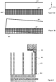
- the first surface 300 and the second surface 302 are completely opposite to each other and the overlap area 304 of the surfaces equals to the area of the smaller surface, here the second surface 302.
- the area of the first surface 300 may be smaller, larger, or equal to the area of the second surface 302.
- the overlap area 304 between the first surface 300 and the second surface reduces, and modulates the balancing electrostatic force between them.
- the voltage difference between the surfaces may be adjusted to an applicable level by calibration. Calibration methods are well known to a person skilled in the art, and will not be discussed in more detail herein.
- the quadrature compensation element may include also a direct current bias voltage source (not shown) that is connected at least to the second conductor 402.
- the first conductor 400 the second conductor 402, and the direct current bias voltage source may thus be connected to jointly generate an electrostatic force that is parallel to the direction of the secondary oscillation and modulated by the primary oscillation of the seismic mass.
- the first surface 404 of the first conductor 400 and the second surface 406 of the second conductor 402 can be considered to form parallel plates that build up a capacitance associated with the electric fields.
- the first spring structure 804 may include a first anchor point 808 within the plane of the first seismic mass 800.
- the first anchor point 808 refers to an element suitable for attaching the first seismic mass 800 to another body element of the gyroscope, for example to an underlying substrate and/or to a covering cap.
- the first anchor point 808 may be, for example, a region patterned into the volume plane of the first seismic mass 800 by removing a material of the seismic mass from the perimeter of the region.
Landscapes
- Engineering & Computer Science (AREA)
- Physics & Mathematics (AREA)
- General Physics & Mathematics (AREA)
- Radar, Positioning & Navigation (AREA)
- Remote Sensing (AREA)
- Signal Processing (AREA)
- Computer Hardware Design (AREA)
- Microelectronics & Electronic Packaging (AREA)
- Gyroscopes (AREA)
Claims (15)
- Mikroelektromechanische Gyroskopstruktur, umfassend:eine seismische Masse (200);ein Körperelement (202);eine die seismische Masse am Körperelement aufhängende Federstruktur (204) zur Gestattung einer Primärschwingung, bei der mindestens ein Teil der seismischen Masse zu einer Schwingung in einer ersten Richtung (1) erregt wird, und einer Sekundärschwingung, bei der mindestens ein Teil der seismischen Masse sich in einer zweiten Richtung (2) senkrecht zur ersten Richtung bewegt, und die seismische Masse umfasst eine Oberflächenebene, die sich planflächig in der zweiten Richtung und in einer dritten Richtung (3) erstreckt, wobei die dritte Richtung senkrecht zur ersten Richtung und zur zweiten Richtung ist;einen ersten Leiter (400), der so angeordnet ist, dass er sich mit der seismischen Masse bewegt, wobei der erste Leiter eine erste Oberfläche (404) aufweist, die sich auf der seismischen Masse in der ersten Richtung und der dritten Richtung erstreckt;einen zweiten Leiter (402), der am Körperelement angebracht ist und eine zweite Oberfläche (406) aufweist, die sich in der ersten Richtung und der dritten Richtung erstreckt, und an die erste Oberfläche angrenzt;dadurch gekennzeichnet,dass ein Spannungselement eingerichtet ist, um zwischen der ersten Oberfläche und der zweiten Oberfläche eine Potenzialdifferenz zu erzeugen und dadurch eine elektrostatische Kraft in der zweiten Richtung zu induzieren, wobei die elektrostatische Kraft durch die Primärschwingung der seismischen Masse moduliert wird.
- Mikroelektromechanische Gyroskopstruktur nach Anspruch 1, dadurch gekennzeichnet, dassdie erste Oberfläche sich planflächig auf einer ersten Höhe in der ersten Richtung erstreckt;die zweite Oberfläche sich planflächig auf einer zweiten Höhe in der ersten Richtung erstreckt;die erste Höhe und die zweite Höhe sich voneinander unterscheiden.
- Mikroelektromechanische Gyroskopstruktur nach Anspruch 1 oder 2, dadurch gekennzeichnet, dass das Spannungselement eine mit dem zweiten Leiter verbundene Gleichstrom-Vorspannungsquelle umfasst.
- Mikroelektromechanische Gyroskopstruktur nach einem der vorhergehenden Ansprüche, dadurch gekennzeichnet, dassdie Federstruktur so ausgelegt ist, dass sie eine maximale Amplitude für die Primärschwingung der seismischen Masse in der ersten Richtung gestattet;die Differenz zwischen der ersten Höhe und der zweiten Höhe gleich oder größer als die maximale Amplitude ist.
- Mikroelektromechanische Gyroskopstruktur nach einem der vorhergehenden Ansprüche 1 bis 4, dadurch gekennzeichnet, dass die zweite Oberfläche höher als die erste Oberfläche ist oder die erste Oberfläche höher als die zweite Oberfläche ist.
- Mikroelektromechanische Gyroskopstruktur nach einem der Ansprüche 1 bis 5, dadurch gekennzeichnet, dassdie Oberflächenebene sich geradlinig in der zweiten Richtung und in der dritten Richtung erstreckt;die seismische Masse zwei erste Seitenebenen umfasst, die sich planflächig in der ersten Richtung und in der dritten Richtung erstrecken;die seismische Masse zwei zweite Seitenebenen umfasst, die sich planflächig in der ersten Richtung und in der zweiten Richtung erstrecken;die Primärschwingung eine Drehschwingung der seismischen Masse um eine Drehachse ist, die parallel zu den zweiten Seitenebenen verläuft und die seismische Masse in zwei Teile untergliedert;der zweite Leiter an die erste Seitenebene angrenzt und der Abstand des zweiten Leiters zur Drehachse im gleichen Teil der seismischen Masse größer ist als der Abstand zur ersten Seitenebene.
- Mikroelektromechanische Gyroskopstruktur nach einem der vorhergehenden Ansprüche, dadurch gekennzeichnet, dass der zweite Leiter mindestens einen länglichen Balken umfasst, wobei eine Oberfläche des länglichen Balkens des zweiten Leiters mit der ersten Oberfläche des ersten Leiters in der seismischen Masse gefluchtet ist.
- Mikroelektromechanische Gyroskopstruktur nach einem der vorhergehenden Ansprüche, dadurch gekennzeichnet, dass der erste Leiter mindestens einen länglichen Balken umfasst und der zweite Leiter mindestens einen länglichen Balken umfasst, wobei eine Oberfläche des länglichen Balkens des ersten Leiters mit einer Oberfläche des länglichen Balkens des zweiten Leiters gefluchtet ist.
- Mikroelektromechanische Gyroskopstruktur nach Anspruch 8, dadurch gekennzeichnet, dass der zweite Leiter zwei längliche Balken umfasst, die miteinander gefluchtet und abständig zueinander angebracht sind, um im zwischen ihnen liegenden Zwischenraum den länglichen Balken des ersten Leiters aufzunehmen.
- Mikroelektromechanische Gyroskopstruktur nach Anspruch 8 oder 9, dadurch gekennzeichnet, dassder erste Leiter und der zweite Leiter eine Mehrzahl von länglichen Balken aufweisen;längliche Balken des ersten Leiters miteinander gefluchtet sind, um eine erste Kammstruktur auszubilden, und längliche Balken des zweiten Leiters miteinander gefluchtet sind, um eine zweite Kammstruktur auszubilden;die erste Kammstruktur und die zweite Kammstruktur gekoppelt sind, um ein periodisches Muster von parallel in einer Ebene liegenden Elektroden auszubilden.
- Mikroelektromechanische Gyroskopstruktur nach Anspruch 10, dadurch gekennzeichnet, dass die länglichen Balken der ersten Kammstruktur und der zweiten Kammstruktur sich parallel zur dritten Richtung erstrecken.
- Mikroelektromechanische Gyroskopstruktur nach Anspruch 10, dadurch gekennzeichnet, dass die länglichen Balken der ersten Kammstruktur und der zweiten Kammstruktur sich parallel zur zweiten Richtung erstrecken.
- Mikroelektromechanische Gyroskopstruktur nach einem der vorhergehenden Ansprüche, dadurch gekennzeichnet, dassdie mikroelektromechanische Gyroskopstruktur eine erste seismische Masse und eine zweite seismische Masse umfasst;die Federstruktur die seismischen Massen am Körperelement aufhängt und eine Drehschwingung der ersten seismischen Masse und der zweiten seismischen Masse um eine gemeinsame Primärachse parallel zur zweiten Richtung gestattet;die Federstruktur auch eine Drehschwingung der ersten seismischen Masse um eine erste Erfassungsachse ermöglicht, die parallel zur ersten Richtung ist;die zweite Federanordnung auch eine Drehschwingung der zweiten seismischen Masse um eine zweite Erfassungsachse ermöglicht, die parallel zur ersten Richtung ist;die erste Erfassungsachse und die zweite Erfassungsachse durch einen Abstand von ungleich null getrennt sind.
- Mikroelektromechanische Gyroskopstruktur nach Anspruch 13, dadurch gekennzeichnet, dass die erste seismische Masse und die zweite seismische Masse jeweils mit mindestens einem Kompensationselement versehen sind, das aus einem ersten Leiter, einem zweiten Leiter und einem Kontrollelement gebildet ist.
- Gyroskop, das die mikroelektromechanische Gyroskopstruktur nach einem der Ansprüche 1 bis 14 umfasst.
Applications Claiming Priority (2)
| Application Number | Priority Date | Filing Date | Title |
|---|---|---|---|
| FI20135916A FI125696B (en) | 2013-09-11 | 2013-09-11 | Gyroscope structure and gyroscope with improved quadrature compensation |
| PCT/IB2014/064375 WO2015036923A1 (en) | 2013-09-11 | 2014-09-10 | Gyroscope structure and gyroscope with improved quadrature compensation |
Publications (2)
| Publication Number | Publication Date |
|---|---|
| EP3044541A1 EP3044541A1 (de) | 2016-07-20 |
| EP3044541B1 true EP3044541B1 (de) | 2018-02-28 |
Family
ID=51626106
Family Applications (1)
| Application Number | Title | Priority Date | Filing Date |
|---|---|---|---|
| EP14776734.7A Active EP3044541B1 (de) | 2013-09-11 | 2014-09-10 | Gyroskopstruktur und gyroskop mit verbesserter quadraturkompensation |
Country Status (8)
| Country | Link |
|---|---|
| US (1) | US9631928B2 (de) |
| EP (1) | EP3044541B1 (de) |
| JP (1) | JP6260706B2 (de) |
| KR (1) | KR101828771B1 (de) |
| CN (1) | CN105556242B (de) |
| FI (1) | FI125696B (de) |
| TW (1) | TWI638142B (de) |
| WO (1) | WO2015036923A1 (de) |
Families Citing this family (15)
| Publication number | Priority date | Publication date | Assignee | Title |
|---|---|---|---|---|
| FI127287B (en) * | 2013-11-01 | 2018-03-15 | Murata Manufacturing Co | Microelectromechanical sensor device with improved quadrature compensation |
| US9612254B2 (en) * | 2014-06-27 | 2017-04-04 | Nxp Usa, Inc. | Microelectromechanical systems devices with improved lateral sensitivity |
| DE102014215038B4 (de) * | 2014-07-31 | 2026-01-22 | Robert Bosch Gmbh | Mikromechanischer Sensor und Verfahren zur Herstellung eines mikromechanischen Sensors |
| FI127042B (en) | 2015-09-09 | 2017-10-13 | Murata Manufacturing Co | An electrode for a microelectromechanical device |
| CN106500732A (zh) * | 2016-12-22 | 2017-03-15 | 四川纳杰微电子技术有限公司 | 一种微机械陀螺仪正交误差补偿结构 |
| US10466067B2 (en) | 2017-01-19 | 2019-11-05 | The Boeing Company | System and method for gyro rate computation for a Coriolis Vibrating Gyroscope |
| FR3065800B1 (fr) * | 2017-04-27 | 2019-08-02 | Safran | Resonateur configure pour etre integre a un capteur angulaire inertiel |
| CN107082405B (zh) * | 2017-05-26 | 2023-08-18 | 深迪半导体(绍兴)有限公司 | 一种mems器件结构 |
| DE102017213815A1 (de) * | 2017-08-08 | 2019-02-14 | Robert Bosch Gmbh | Drehratensensor mit einem Substrat, Herstellungsverfahren für einen Drehratensensor |
| JP7225817B2 (ja) * | 2019-01-17 | 2023-02-21 | セイコーエプソン株式会社 | 角速度センサー、慣性計測装置、電子機器および移動体 |
| US11377346B2 (en) | 2019-09-11 | 2022-07-05 | Murata Manufacturing Co., Ltd. | Low-noise multi axis MEMS accelerometer |
| EP3792637B1 (de) | 2019-09-11 | 2023-05-03 | Murata Manufacturing Co., Ltd. | Rauscharmer mehrachsiger mems-beschleunigungsmesser |
| CN113804171B (zh) * | 2021-09-16 | 2024-10-29 | 美新半导体(天津)有限公司 | Mems陀螺仪 |
| US11994390B2 (en) | 2022-02-09 | 2024-05-28 | Honeywell International Inc. | Vibratory sensor with electronic balancing |
| CN114397696B (zh) * | 2022-03-23 | 2022-06-21 | 中国科学院地质与地球物理研究所 | 基于低功耗mems传感器的地震采集系统和传感器 |
Family Cites Families (36)
| Publication number | Priority date | Publication date | Assignee | Title |
|---|---|---|---|---|
| US5600065A (en) * | 1995-10-25 | 1997-02-04 | Motorola, Inc. | Angular velocity sensor |
| JP3039364B2 (ja) * | 1996-03-11 | 2000-05-08 | 株式会社村田製作所 | 角速度センサ |
| US6250156B1 (en) * | 1996-05-31 | 2001-06-26 | The Regents Of The University Of California | Dual-mass micromachined vibratory rate gyroscope |
| US5992233A (en) * | 1996-05-31 | 1999-11-30 | The Regents Of The University Of California | Micromachined Z-axis vibratory rate gyroscope |
| JP3525862B2 (ja) * | 2000-05-22 | 2004-05-10 | トヨタ自動車株式会社 | センサ素子及びセンサ装置 |
| JP2001336936A (ja) * | 2000-05-29 | 2001-12-07 | Alps Electric Co Ltd | ジャイロスコープおよび入力装置 |
| JP3649090B2 (ja) * | 2000-06-16 | 2005-05-18 | 株式会社村田製作所 | 振動ジャイロ用振動子及びそれを用いた振動ジャイロ及びそれを用いた電子装置 |
| US6742389B2 (en) * | 2001-01-24 | 2004-06-01 | The Regents Of The University Of Michigan | Filter-based method and system for measuring angular speed of an object |
| DE60120921T2 (de) * | 2001-04-27 | 2007-02-01 | Stmicroelectronics S.R.L., Agrate Brianza | Aus Halbleitermaterial hergestellter integrierter Kreisel |
| WO2002088631A2 (en) * | 2001-05-02 | 2002-11-07 | The Regents Of The University Of California | Non-resonant four degrees-of-freedom micromachined gyroscope |
| US20030033850A1 (en) * | 2001-08-09 | 2003-02-20 | Challoner A. Dorian | Cloverleaf microgyroscope with electrostatic alignment and tuning |
| US6611168B1 (en) * | 2001-12-19 | 2003-08-26 | Analog Devices, Inc. | Differential parametric amplifier with physically-coupled electrically-isolated micromachined structures |
| FR2846740B1 (fr) * | 2002-11-05 | 2005-02-04 | Thales Sa | Capteur gyrometrique micro-usine, a detection dans le plan de la plaque usinee |
| DE10320725A1 (de) * | 2003-05-08 | 2004-11-25 | Robert Bosch Gmbh | Mikromechanischer Bewegungssensor |
| US7036372B2 (en) * | 2003-09-25 | 2006-05-02 | Kionix, Inc. | Z-axis angular rate sensor |
| US7043985B2 (en) * | 2004-01-13 | 2006-05-16 | Georgia Tech Research Corporation | High-resolution in-plane tuning fork gyroscope and methods of fabrication |
| JP4512636B2 (ja) * | 2004-04-14 | 2010-07-28 | アナログ デバイシス, インコーポレイテッド | 直線的にアレイされたセンサエレメントを有する慣性センサ |
| KR100652952B1 (ko) | 2004-07-19 | 2006-12-06 | 삼성전자주식회사 | 커플링 스프링을 구비한 멤스 자이로스코프 |
| EP1624286B1 (de) * | 2004-08-03 | 2017-10-04 | STMicroelectronics Srl | Mikroelektromechanischer Sensor mit Kraft-Rückkopplungsschleife |
| FI116544B (fi) | 2004-12-31 | 2005-12-15 | Vti Technologies Oy | Värähtelevä mikromekaaninen kulmanopeusanturi |
| US7213458B2 (en) * | 2005-03-22 | 2007-05-08 | Honeywell International Inc. | Quadrature reduction in MEMS gyro devices using quad steering voltages |
| US7240552B2 (en) * | 2005-06-06 | 2007-07-10 | Bei Technologies, Inc. | Torsional rate sensor with momentum balance and mode decoupling |
| US7461552B2 (en) * | 2006-10-23 | 2008-12-09 | Custom Sensors & Technologies, Inc. | Dual axis rate sensor |
| EP2092272B1 (de) | 2006-12-15 | 2015-01-21 | Atlantic Inertial Systems Limited | Verbesserungen in bezug auf einen kreisel |
| US8141424B2 (en) * | 2008-09-12 | 2012-03-27 | Invensense, Inc. | Low inertia frame for detecting coriolis acceleration |
| US8047075B2 (en) * | 2007-06-21 | 2011-11-01 | Invensense, Inc. | Vertically integrated 3-axis MEMS accelerometer with electronics |
| US7950281B2 (en) * | 2007-02-28 | 2011-05-31 | Infineon Technologies Ag | Sensor and method for sensing linear acceleration and angular velocity |
| GB0720412D0 (en) | 2007-10-18 | 2007-11-28 | Melexis Nv | Combined mems accelerometer and gyroscope |
| FI122397B (fi) * | 2008-04-16 | 2011-12-30 | Vti Technologies Oy | Värähtelevä mikromekaaninen kulmanopeusanturi |
| DE102008043796B4 (de) * | 2008-11-17 | 2023-12-21 | Robert Bosch Gmbh | Drehratensensor |
| ITTO20091042A1 (it) * | 2009-12-24 | 2011-06-25 | St Microelectronics Srl | Giroscopio integrato microelettromeccanico con migliorata struttura di azionamento |
| EP2378246A1 (de) * | 2010-04-16 | 2011-10-19 | SensoNor Technologies AS | MEMS-Struktur für einen Winkelgeschwindigkeitssensor |
| TWI411766B (zh) * | 2010-04-27 | 2013-10-11 | Univ Nat Chiao Tung | Uniaxial Control Input Gyroscope System with Flaw Compensation. |
| JP2013108929A (ja) * | 2011-11-24 | 2013-06-06 | Mitsubishi Precision Co Ltd | 高精度化された振動型ジャイロ |
| DE102011056971A1 (de) * | 2011-12-23 | 2013-06-27 | Maxim Integrated Products, Inc. | Mikromechanischer Coriolis-Drehratensensor |
| US20140144232A1 (en) * | 2012-11-28 | 2014-05-29 | Yizhen Lin | Spring for microelectromechanical systems (mems) device |
-
2013
- 2013-09-11 FI FI20135916A patent/FI125696B/en active IP Right Grant
-
2014
- 2014-09-10 US US14/481,969 patent/US9631928B2/en active Active
- 2014-09-10 TW TW103131129A patent/TWI638142B/zh active
- 2014-09-10 KR KR1020167009487A patent/KR101828771B1/ko active Active
- 2014-09-10 JP JP2016542417A patent/JP6260706B2/ja active Active
- 2014-09-10 CN CN201480050415.8A patent/CN105556242B/zh active Active
- 2014-09-10 WO PCT/IB2014/064375 patent/WO2015036923A1/en not_active Ceased
- 2014-09-10 EP EP14776734.7A patent/EP3044541B1/de active Active
Also Published As
| Publication number | Publication date |
|---|---|
| US9631928B2 (en) | 2017-04-25 |
| FI20135916L (fi) | 2015-03-12 |
| KR101828771B1 (ko) | 2018-02-13 |
| JP6260706B2 (ja) | 2018-01-17 |
| KR20160052732A (ko) | 2016-05-12 |
| WO2015036923A1 (en) | 2015-03-19 |
| US20150082885A1 (en) | 2015-03-26 |
| TW201518686A (zh) | 2015-05-16 |
| FI125696B (en) | 2016-01-15 |
| CN105556242A (zh) | 2016-05-04 |
| EP3044541A1 (de) | 2016-07-20 |
| CN105556242B (zh) | 2018-09-04 |
| JP2016530541A (ja) | 2016-09-29 |
| TWI638142B (zh) | 2018-10-11 |
Similar Documents
| Publication | Publication Date | Title |
|---|---|---|
| US9631928B2 (en) | Gyroscope structure and gyroscope with improved quadrature compensation | |
| US9452921B2 (en) | Gyroscope structure and gyroscope | |
| US10365103B2 (en) | Gyroscope structure and gyroscope | |
| US9897447B2 (en) | Quadrature compensation | |
| CN101151507B (zh) | 振荡微机械角速度传感器 | |
| FI126557B (en) | Improved gyroscope structure and gyroscope |
Legal Events
| Date | Code | Title | Description |
|---|---|---|---|
| PUAI | Public reference made under article 153(3) epc to a published international application that has entered the european phase |
Free format text: ORIGINAL CODE: 0009012 |
|
| 17P | Request for examination filed |
Effective date: 20160408 |
|
| AK | Designated contracting states |
Kind code of ref document: A1 Designated state(s): AL AT BE BG CH CY CZ DE DK EE ES FI FR GB GR HR HU IE IS IT LI LT LU LV MC MK MT NL NO PL PT RO RS SE SI SK SM TR |
|
| AX | Request for extension of the european patent |
Extension state: BA ME |
|
| DAX | Request for extension of the european patent (deleted) | ||
| GRAP | Despatch of communication of intention to grant a patent |
Free format text: ORIGINAL CODE: EPIDOSNIGR1 |
|
| STAA | Information on the status of an ep patent application or granted ep patent |
Free format text: STATUS: GRANT OF PATENT IS INTENDED |
|
| INTG | Intention to grant announced |
Effective date: 20170926 |
|
| GRAS | Grant fee paid |
Free format text: ORIGINAL CODE: EPIDOSNIGR3 |
|
| GRAA | (expected) grant |
Free format text: ORIGINAL CODE: 0009210 |
|
| STAA | Information on the status of an ep patent application or granted ep patent |
Free format text: STATUS: THE PATENT HAS BEEN GRANTED |
|
| AK | Designated contracting states |
Kind code of ref document: B1 Designated state(s): AL AT BE BG CH CY CZ DE DK EE ES FI FR GB GR HR HU IE IS IT LI LT LU LV MC MK MT NL NO PL PT RO RS SE SI SK SM TR |
|
| REG | Reference to a national code |
Ref country code: GB Ref legal event code: FG4D Ref country code: CH Ref legal event code: EP |
|
| REG | Reference to a national code |
Ref country code: AT Ref legal event code: REF Ref document number: 974634 Country of ref document: AT Kind code of ref document: T Effective date: 20180315 |
|
| REG | Reference to a national code |
Ref country code: IE Ref legal event code: FG4D |
|
| REG | Reference to a national code |
Ref country code: DE Ref legal event code: R096 Ref document number: 602014021676 Country of ref document: DE |
|
| REG | Reference to a national code |
Ref country code: NL Ref legal event code: MP Effective date: 20180228 |
|
| REG | Reference to a national code |
Ref country code: LT Ref legal event code: MG4D |
|
| REG | Reference to a national code |
Ref country code: AT Ref legal event code: MK05 Ref document number: 974634 Country of ref document: AT Kind code of ref document: T Effective date: 20180228 |
|
| PG25 | Lapsed in a contracting state [announced via postgrant information from national office to epo] |
Ref country code: FI Free format text: LAPSE BECAUSE OF FAILURE TO SUBMIT A TRANSLATION OF THE DESCRIPTION OR TO PAY THE FEE WITHIN THE PRESCRIBED TIME-LIMIT Effective date: 20180228 Ref country code: HR Free format text: LAPSE BECAUSE OF FAILURE TO SUBMIT A TRANSLATION OF THE DESCRIPTION OR TO PAY THE FEE WITHIN THE PRESCRIBED TIME-LIMIT Effective date: 20180228 Ref country code: CY Free format text: LAPSE BECAUSE OF FAILURE TO SUBMIT A TRANSLATION OF THE DESCRIPTION OR TO PAY THE FEE WITHIN THE PRESCRIBED TIME-LIMIT Effective date: 20180228 Ref country code: LT Free format text: LAPSE BECAUSE OF FAILURE TO SUBMIT A TRANSLATION OF THE DESCRIPTION OR TO PAY THE FEE WITHIN THE PRESCRIBED TIME-LIMIT Effective date: 20180228 Ref country code: NL Free format text: LAPSE BECAUSE OF FAILURE TO SUBMIT A TRANSLATION OF THE DESCRIPTION OR TO PAY THE FEE WITHIN THE PRESCRIBED TIME-LIMIT Effective date: 20180228 Ref country code: NO Free format text: LAPSE BECAUSE OF FAILURE TO SUBMIT A TRANSLATION OF THE DESCRIPTION OR TO PAY THE FEE WITHIN THE PRESCRIBED TIME-LIMIT Effective date: 20180528 Ref country code: ES Free format text: LAPSE BECAUSE OF FAILURE TO SUBMIT A TRANSLATION OF THE DESCRIPTION OR TO PAY THE FEE WITHIN THE PRESCRIBED TIME-LIMIT Effective date: 20180228 |
|
| PG25 | Lapsed in a contracting state [announced via postgrant information from national office to epo] |
Ref country code: BG Free format text: LAPSE BECAUSE OF FAILURE TO SUBMIT A TRANSLATION OF THE DESCRIPTION OR TO PAY THE FEE WITHIN THE PRESCRIBED TIME-LIMIT Effective date: 20180528 Ref country code: RS Free format text: LAPSE BECAUSE OF FAILURE TO SUBMIT A TRANSLATION OF THE DESCRIPTION OR TO PAY THE FEE WITHIN THE PRESCRIBED TIME-LIMIT Effective date: 20180228 Ref country code: AT Free format text: LAPSE BECAUSE OF FAILURE TO SUBMIT A TRANSLATION OF THE DESCRIPTION OR TO PAY THE FEE WITHIN THE PRESCRIBED TIME-LIMIT Effective date: 20180228 Ref country code: LV Free format text: LAPSE BECAUSE OF FAILURE TO SUBMIT A TRANSLATION OF THE DESCRIPTION OR TO PAY THE FEE WITHIN THE PRESCRIBED TIME-LIMIT Effective date: 20180228 Ref country code: SE Free format text: LAPSE BECAUSE OF FAILURE TO SUBMIT A TRANSLATION OF THE DESCRIPTION OR TO PAY THE FEE WITHIN THE PRESCRIBED TIME-LIMIT Effective date: 20180228 Ref country code: GR Free format text: LAPSE BECAUSE OF FAILURE TO SUBMIT A TRANSLATION OF THE DESCRIPTION OR TO PAY THE FEE WITHIN THE PRESCRIBED TIME-LIMIT Effective date: 20180529 |
|
| REG | Reference to a national code |
Ref country code: FR Ref legal event code: PLFP Year of fee payment: 5 |
|
| PG25 | Lapsed in a contracting state [announced via postgrant information from national office to epo] |
Ref country code: EE Free format text: LAPSE BECAUSE OF FAILURE TO SUBMIT A TRANSLATION OF THE DESCRIPTION OR TO PAY THE FEE WITHIN THE PRESCRIBED TIME-LIMIT Effective date: 20180228 Ref country code: PL Free format text: LAPSE BECAUSE OF FAILURE TO SUBMIT A TRANSLATION OF THE DESCRIPTION OR TO PAY THE FEE WITHIN THE PRESCRIBED TIME-LIMIT Effective date: 20180228 Ref country code: RO Free format text: LAPSE BECAUSE OF FAILURE TO SUBMIT A TRANSLATION OF THE DESCRIPTION OR TO PAY THE FEE WITHIN THE PRESCRIBED TIME-LIMIT Effective date: 20180228 Ref country code: AL Free format text: LAPSE BECAUSE OF FAILURE TO SUBMIT A TRANSLATION OF THE DESCRIPTION OR TO PAY THE FEE WITHIN THE PRESCRIBED TIME-LIMIT Effective date: 20180228 |
|
| REG | Reference to a national code |
Ref country code: DE Ref legal event code: R097 Ref document number: 602014021676 Country of ref document: DE |
|
| PG25 | Lapsed in a contracting state [announced via postgrant information from national office to epo] |
Ref country code: DK Free format text: LAPSE BECAUSE OF FAILURE TO SUBMIT A TRANSLATION OF THE DESCRIPTION OR TO PAY THE FEE WITHIN THE PRESCRIBED TIME-LIMIT Effective date: 20180228 Ref country code: SK Free format text: LAPSE BECAUSE OF FAILURE TO SUBMIT A TRANSLATION OF THE DESCRIPTION OR TO PAY THE FEE WITHIN THE PRESCRIBED TIME-LIMIT Effective date: 20180228 Ref country code: SM Free format text: LAPSE BECAUSE OF FAILURE TO SUBMIT A TRANSLATION OF THE DESCRIPTION OR TO PAY THE FEE WITHIN THE PRESCRIBED TIME-LIMIT Effective date: 20180228 Ref country code: CZ Free format text: LAPSE BECAUSE OF FAILURE TO SUBMIT A TRANSLATION OF THE DESCRIPTION OR TO PAY THE FEE WITHIN THE PRESCRIBED TIME-LIMIT Effective date: 20180228 |
|
| PLBE | No opposition filed within time limit |
Free format text: ORIGINAL CODE: 0009261 |
|
| STAA | Information on the status of an ep patent application or granted ep patent |
Free format text: STATUS: NO OPPOSITION FILED WITHIN TIME LIMIT |
|
| 26N | No opposition filed |
Effective date: 20181129 |
|
| PG25 | Lapsed in a contracting state [announced via postgrant information from national office to epo] |
Ref country code: SI Free format text: LAPSE BECAUSE OF FAILURE TO SUBMIT A TRANSLATION OF THE DESCRIPTION OR TO PAY THE FEE WITHIN THE PRESCRIBED TIME-LIMIT Effective date: 20180228 |
|
| PG25 | Lapsed in a contracting state [announced via postgrant information from national office to epo] |
Ref country code: MC Free format text: LAPSE BECAUSE OF FAILURE TO SUBMIT A TRANSLATION OF THE DESCRIPTION OR TO PAY THE FEE WITHIN THE PRESCRIBED TIME-LIMIT Effective date: 20180228 |
|
| REG | Reference to a national code |
Ref country code: CH Ref legal event code: PL |
|
| GBPC | Gb: european patent ceased through non-payment of renewal fee |
Effective date: 20180910 |
|
| REG | Reference to a national code |
Ref country code: BE Ref legal event code: MM Effective date: 20180930 |
|
| REG | Reference to a national code |
Ref country code: IE Ref legal event code: MM4A |
|
| PG25 | Lapsed in a contracting state [announced via postgrant information from national office to epo] |
Ref country code: LU Free format text: LAPSE BECAUSE OF NON-PAYMENT OF DUE FEES Effective date: 20180910 |
|
| PG25 | Lapsed in a contracting state [announced via postgrant information from national office to epo] |
Ref country code: IE Free format text: LAPSE BECAUSE OF NON-PAYMENT OF DUE FEES Effective date: 20180910 |
|
| PG25 | Lapsed in a contracting state [announced via postgrant information from national office to epo] |
Ref country code: CH Free format text: LAPSE BECAUSE OF NON-PAYMENT OF DUE FEES Effective date: 20180930 Ref country code: LI Free format text: LAPSE BECAUSE OF NON-PAYMENT OF DUE FEES Effective date: 20180930 Ref country code: BE Free format text: LAPSE BECAUSE OF NON-PAYMENT OF DUE FEES Effective date: 20180930 |
|
| PG25 | Lapsed in a contracting state [announced via postgrant information from national office to epo] |
Ref country code: GB Free format text: LAPSE BECAUSE OF NON-PAYMENT OF DUE FEES Effective date: 20180910 |
|
| PG25 | Lapsed in a contracting state [announced via postgrant information from national office to epo] |
Ref country code: MT Free format text: LAPSE BECAUSE OF NON-PAYMENT OF DUE FEES Effective date: 20180910 |
|
| PG25 | Lapsed in a contracting state [announced via postgrant information from national office to epo] |
Ref country code: TR Free format text: LAPSE BECAUSE OF FAILURE TO SUBMIT A TRANSLATION OF THE DESCRIPTION OR TO PAY THE FEE WITHIN THE PRESCRIBED TIME-LIMIT Effective date: 20180228 |
|
| PG25 | Lapsed in a contracting state [announced via postgrant information from national office to epo] |
Ref country code: PT Free format text: LAPSE BECAUSE OF FAILURE TO SUBMIT A TRANSLATION OF THE DESCRIPTION OR TO PAY THE FEE WITHIN THE PRESCRIBED TIME-LIMIT Effective date: 20180228 |
|
| PG25 | Lapsed in a contracting state [announced via postgrant information from national office to epo] |
Ref country code: MK Free format text: LAPSE BECAUSE OF NON-PAYMENT OF DUE FEES Effective date: 20180228 Ref country code: HU Free format text: LAPSE BECAUSE OF FAILURE TO SUBMIT A TRANSLATION OF THE DESCRIPTION OR TO PAY THE FEE WITHIN THE PRESCRIBED TIME-LIMIT; INVALID AB INITIO Effective date: 20140910 |
|
| PG25 | Lapsed in a contracting state [announced via postgrant information from national office to epo] |
Ref country code: IS Free format text: LAPSE BECAUSE OF FAILURE TO SUBMIT A TRANSLATION OF THE DESCRIPTION OR TO PAY THE FEE WITHIN THE PRESCRIBED TIME-LIMIT Effective date: 20180628 |
|
| PGFP | Annual fee paid to national office [announced via postgrant information from national office to epo] |
Ref country code: DE Payment date: 20250919 Year of fee payment: 12 |
|
| PGFP | Annual fee paid to national office [announced via postgrant information from national office to epo] |
Ref country code: IT Payment date: 20250923 Year of fee payment: 12 |
|
| PGFP | Annual fee paid to national office [announced via postgrant information from national office to epo] |
Ref country code: FR Payment date: 20250922 Year of fee payment: 12 |