EP3043884B1 - Procede regeneratif d'elimination des composes siloxanes dans du biogaz - Google Patents
Procede regeneratif d'elimination des composes siloxanes dans du biogaz Download PDFInfo
- Publication number
- EP3043884B1 EP3043884B1 EP14784282.7A EP14784282A EP3043884B1 EP 3043884 B1 EP3043884 B1 EP 3043884B1 EP 14784282 A EP14784282 A EP 14784282A EP 3043884 B1 EP3043884 B1 EP 3043884B1
- Authority
- EP
- European Patent Office
- Prior art keywords
- filter
- biogas
- gas
- siloxanes
- bar
- Prior art date
- Legal status (The legal status is an assumption and is not a legal conclusion. Google has not performed a legal analysis and makes no representation as to the accuracy of the status listed.)
- Active
Links
Images
Classifications
-
- B—PERFORMING OPERATIONS; TRANSPORTING
- B01—PHYSICAL OR CHEMICAL PROCESSES OR APPARATUS IN GENERAL
- B01D—SEPARATION
- B01D53/00—Separation of gases or vapours; Recovering vapours of volatile solvents from gases; Chemical or biological purification of waste gases, e.g. engine exhaust gases, smoke, fumes, flue gases, aerosols
- B01D53/02—Separation of gases or vapours; Recovering vapours of volatile solvents from gases; Chemical or biological purification of waste gases, e.g. engine exhaust gases, smoke, fumes, flue gases, aerosols by adsorption, e.g. preparative gas chromatography
- B01D53/04—Separation of gases or vapours; Recovering vapours of volatile solvents from gases; Chemical or biological purification of waste gases, e.g. engine exhaust gases, smoke, fumes, flue gases, aerosols by adsorption, e.g. preparative gas chromatography with stationary adsorbents
- B01D53/0454—Controlling adsorption
-
- B—PERFORMING OPERATIONS; TRANSPORTING
- B01—PHYSICAL OR CHEMICAL PROCESSES OR APPARATUS IN GENERAL
- B01D—SEPARATION
- B01D53/00—Separation of gases or vapours; Recovering vapours of volatile solvents from gases; Chemical or biological purification of waste gases, e.g. engine exhaust gases, smoke, fumes, flue gases, aerosols
- B01D53/02—Separation of gases or vapours; Recovering vapours of volatile solvents from gases; Chemical or biological purification of waste gases, e.g. engine exhaust gases, smoke, fumes, flue gases, aerosols by adsorption, e.g. preparative gas chromatography
- B01D53/04—Separation of gases or vapours; Recovering vapours of volatile solvents from gases; Chemical or biological purification of waste gases, e.g. engine exhaust gases, smoke, fumes, flue gases, aerosols by adsorption, e.g. preparative gas chromatography with stationary adsorbents
- B01D53/0407—Constructional details of adsorbing systems
- B01D53/0438—Cooling or heating systems
-
- B—PERFORMING OPERATIONS; TRANSPORTING
- B01—PHYSICAL OR CHEMICAL PROCESSES OR APPARATUS IN GENERAL
- B01D—SEPARATION
- B01D2253/00—Adsorbents used in seperation treatment of gases and vapours
- B01D2253/10—Inorganic adsorbents
- B01D2253/102—Carbon
-
- B—PERFORMING OPERATIONS; TRANSPORTING
- B01—PHYSICAL OR CHEMICAL PROCESSES OR APPARATUS IN GENERAL
- B01D—SEPARATION
- B01D2253/00—Adsorbents used in seperation treatment of gases and vapours
- B01D2253/30—Physical properties of adsorbents
- B01D2253/34—Specific shapes
-
- B—PERFORMING OPERATIONS; TRANSPORTING
- B01—PHYSICAL OR CHEMICAL PROCESSES OR APPARATUS IN GENERAL
- B01D—SEPARATION
- B01D2256/00—Main component in the product gas stream after treatment
- B01D2256/24—Hydrocarbons
- B01D2256/245—Methane
-
- B—PERFORMING OPERATIONS; TRANSPORTING
- B01—PHYSICAL OR CHEMICAL PROCESSES OR APPARATUS IN GENERAL
- B01D—SEPARATION
- B01D2257/00—Components to be removed
- B01D2257/55—Compounds of silicon, phosphorus, germanium or arsenic
-
- B—PERFORMING OPERATIONS; TRANSPORTING
- B01—PHYSICAL OR CHEMICAL PROCESSES OR APPARATUS IN GENERAL
- B01D—SEPARATION
- B01D2258/00—Sources of waste gases
- B01D2258/05—Biogas
-
- B—PERFORMING OPERATIONS; TRANSPORTING
- B01—PHYSICAL OR CHEMICAL PROCESSES OR APPARATUS IN GENERAL
- B01D—SEPARATION
- B01D2259/00—Type of treatment
- B01D2259/40—Further details for adsorption processes and devices
- B01D2259/40083—Regeneration of adsorbents in processes other than pressure or temperature swing adsorption
- B01D2259/40088—Regeneration of adsorbents in processes other than pressure or temperature swing adsorption by heating
- B01D2259/40096—Regeneration of adsorbents in processes other than pressure or temperature swing adsorption by heating by using electrical resistance heating
Definitions
- the present invention is situated in the context of the purification of biogas. More specifically, this invention relates to a process for removing siloxane compounds from biogas.
- Biogas is a combustible gas obtained by fermentation, also called methanisation, of organic waste of animal or vegetable origin in the absence of oxygen. It is mainly composed of methane and carbon dioxide. There is also conventionally a little nitrogen, very little oxygen, water vapor, hydrogen sulfide (H 2 S) and many other substances in very small quantities, in particular volatile organic compounds ( VOCs), polycyclic aromatic hydrocarbons (PAHs), halogenated compounds, heavy metals and siloxanes. The nature and content of these substances vary in particular depending on the methanisation process and the nature of the methanized matter.
- Biogas can be used as a fuel to replace natural gas. However, depending on the intended uses, it may be necessary to purify the biogas to remove certain contaminating substances. For example, when using biogas as a motor fuel, it is necessary to eliminate the siloxane compounds because, oxidized at high temperatures, the siloxanes form deposits of silica which can seriously damage the equipment.
- the American patent application US 2013/0137567 presents a method of removing siloxanes from biogas using a regenerable adsorbent material.
- the regenerable material used is activated carbon in the form of granules placed inside a tubular enclosure of rectangular section formed by two electrodes and two dielectric elements respectively disposed face to face.
- the activated carbon When the activated carbon is saturated with contaminant, it can be regenerated by passing an electric current between the two electrodes of the device.
- this technical solution poses a problem in maintaining the electrical contact between the two electrodes: if the contact between the grains of activated carbon is too low, the electrical resistance of the regenerable material becomes too high and the electrical current no longer flows correctly.
- this US patent application US 2013/0137567 proposes the installation of a vibrating element intended to homogenize the contacts between the granules of activated carbon.
- this solution is not optimal: the presence of this vibrating element makes the device more complex, more expensive to manufacture, and difficult to reproduce on a large installation.
- the regenerable material consisting of activated carbon in the form of granules has a high electrical resistance, so that the electrical power necessary to obtain sufficient regeneration is high.
- One of the objectives of the present invention is to propose a new regenerative process for removing siloxanes from a biogas which is more effective than those of the prior art.
- European patent application EP 0818617 A describes an engine arrangement comprising a gas engine supplied with fuel gas, a catalytic converter placed downstream of the engine gas and a cleaning device which adsorbs the contaminants contained in the gas, this device being placed upstream of the engine.
- the main contaminants targeted by this invention are siloxanes, contained in biogas.
- the adsorbent is an activated carbon filter. However, its regeneration takes place at very high temperatures (between 350 and 450 ° C).
- the American patent application US 2012/0024157 A1 describes a process for purifying biogas. This process is based on the use of several layers of adsorbents which make it possible to adsorb, inter alia, water, hydrogen sulfide and the siloxanes contained in the biogas.
- the filter used to adsorb the siloxanes is made of activated carbon. The regeneration of this filter can be done by heating up to 200 ° F.
- the adsorption and regeneration properties of an adsorbent material depend very largely on the nature of the adsorbed compound, its concentration and the nature and concentration of the other chemical species of the gas containing the contaminating compound.
- the regeneration step during which an electric current is applied in the adsorbent material is carried out in the absence of a scanning current.
- the present invention thus relates to a process for the treatment of a biogas containing siloxanes according to claim 1.
- the subject of the invention is a method for treating a biogas.
- a “combustible gas” resulting from the fermentation of organic waste of animal or vegetable origin in the absence of oxygen, which consists mainly of methane and carbon dioxide, is called “biogas”. It can be a biogas obtained from landfills, treatment plants or agricultural sources.
- biogas typically includes 40% to 70% methane and 60% to 30% carbon dioxide.
- biogas can typically contain nitrogen, oxygen, water vapor, hydrogen sulfide (H 2 S), volatile organic compounds (VOCs), polycyclic aromatic hydrocarbons (PAHs), halogenated compounds, heavy metals and siloxanes.
- H 2 S hydrogen sulfide
- VOCs volatile organic compounds
- PAHs polycyclic aromatic hydrocarbons
- halogenated compounds heavy metals and siloxanes.
- the biogas treated in the invention contains siloxanes which are considered to be contaminants and which it is desired to remove from the biogas.
- laminate of the siloxanes is meant in the present description a treatment making it possible to remove at least in part, preferably at least 50%, more preferably at least 70%, even more preferably at least 90%, and preferably completely, the siloxane compounds present in the biogas to be treated.
- the process of the present invention can advantageously be a process for removing siloxanes.
- siloxanes or “siloxane compounds” is meant here all of the chemical compounds formed from silicon-oxygen Si-O chains where organic groups bond to the silicon atoms. Due to their particularly interesting physicochemical properties, siloxanes are very widely used in manufacturing processes and in commercial products such as cosmetic products (creams, shampoos %), cleaning and maintenance products, varnishes, resins, paints and other surface treatments, adhesives and glues, plasticized packaging, sizing and textile treatment processes, protective equipment, electrical and electronic equipment, parts for medical and pharmacy. At the end of their life, these products and the siloxanes they contain are found among household and industrial waste, then the siloxanes are found in the biogas obtained by fermentation of this waste.
- the concentration of siloxanes in biogas is very variable: studies have shown that the concentration of siloxanes in biogas could range from 1.6 mg / Nm 3 for the lowest values recorded up to 140 mg / Nm 3 .
- the biogas treated in the process according to the invention contains from 5 mg / Nm 3 to 250 mg / Nm 3 of siloxanes.
- siloxanes are not very reactive chemical compounds.
- the biogas treatment process according to the invention comprises a step (a) consisting in filtering a stream of biogas containing siloxanes with an active carbon fabric filter so as to adsorb siloxanes in said filter.
- Activated carbon is a material well known to those skilled in the art, especially for its uses as an adsorbent. It can be in various forms, for example in the form of granules or GAC (for “Granular Activated Carbon”) or in the form of powder or PAC (for “Powdered Activated Carbon”), which are the most common forms. Activated carbon in powder form can be used with a binder to form solid blocks. Activated carbon can also be obtained in the form of fibers which can be used to form fabrics or felts.
- the filter is an activated carbon cloth or ACC (for "Activated Carbon Cloth”). It can be chosen from woven and knitted fabrics. The appearance of an activated carbon fabric is that of an ordinary fabric.
- the flexible structure of the activated carbon fabric allows easy shaping. Its thickness can be between 0 mm and 5 mm, preferably between 0 mm and 2 mm and more preferably between 0 mm and 1 mm. Due to the porosity of the activated carbon fibers and their weaving or knitting, the activated carbon fabric has a high specific surface, preferably more than 1000 m 2 / g, more preferably more than 1500 m 2 / g and even more preferably greater than 2000 m 2 / g, measured according to the BET method (Brunauer-Emmett-Teller).
- the pore volume may preferably be greater than 0.3 cm 3 / g, more preferably greater than 0.5 cm 3 / g and so even more preferred greater than 1.0 cm 3 / g.
- the structure is preferably microporous, that is to say provided with pores whose diameter does not exceed 2 nanometers.
- the microporous volume percentage is preferably more than 30%, more preferably more than 50% and even more preferably more than 75%.
- Activated carbon fabrics are currently commercially available for applications such as filtration, adsorption and separation. Mention may in particular be made of the woven fabrics and the knitted fabrics available from Calgon Carbon under the name of Zorflex® ACC.
- Step (a) of the process according to the invention corresponds to the phase of adsorption by the active carbon fabric filter of the siloxanes contained in the biogas.
- a biogas gas stream is sent to one of the faces of the filter.
- the adsorption is preferably carried out at a temperature between 0 ° C and 100 ° C, more preferably between 0 ° C and 50 ° C, and even more preferably between 0 ° C and 35 ° C.
- the biogas pressure during filtration step (a) is preferably between 0 bar and 20 bar, more preferably between 0 bar and 10 bar, and even more preferably between 0 bar and 1 bar (pressure relative, by difference with atmospheric pressure).
- the gas flow collected at the outlet of the filter advantageously has a siloxane concentration of less than 2 mg / Nm 3 , preferably less than 1 mg / Nm 3 , and more preferably between 0 and 0.5 mg / Nm 3 .
- step (a) is continued for a time denoted Ta.
- step (a) is stopped after a time defined beforehand and which preferably corresponds to the saturation of the filter.
- the siloxane concentration is measured continuously in the gas flow collected at the outlet of the filter.
- Step (a) can be stopped when the measured siloxane concentration exceeds a previously defined threshold, preferably around 5 mg / Nm 3 , more preferably around 3 mg / Nm 3 , and even more preferably around 1 mg / Nm 3 .
- the time Ta is preferably between 1 hour and 24 hours, and more preferably between 8 hours and 24 hours.
- the biogas treatment method according to the invention further comprises a step (b1) consisting in regenerating said filter.
- This step (b1) corresponds to the phase of desorption of the siloxanes by the active carbon fabric filter.
- an activated carbon fabric filter is a good electrical conductor. It is therefore possible to circulate an electric current in the filter.
- the filter is connected to two electrodes and connected to an electric generator.
- a direct electric current is applied to the filter. The circulation of electric current in the filter creates heat by the Joule effect.
- the filter is subjected to a purging gas flow.
- a sweeping gas flow is sent to one of the faces of the filter.
- the purging gas is preferably chosen from the group consisting of air, depleted air, an inert gas such as nitrogen or carbon dioxide, methane or a biogas already treated.
- the sweep gas is air.
- the passage of the purging gas flow during step (b1) can be carried out in co-current or against the current with respect to the passage of biogas during step (a).
- the purge gas can itself be heated to maintain or accelerate the heating of the filter. If the gas is not heated, its flow is optimized so as not to cool the filter.
- the treatment method also comprises a step (b2) of thermal destruction of the sweeping gas used in step (b1).
- the destruction of the purging gas due to its low flow rate, can be carried out by a very poor gas burner, requiring only between 1 and 10% by volume of methane, preferably between 1 and 6%, and even more preferably between 1 and 3%, for auto-thermal operation.
- the sweeping gas can also be destroyed by a regenerative or non-regenerative thermal oxidation system.
- Type impurities siloxane are preferably oxidized at elevated temperatures, typically 800 to 850 ° C or even higher for a period of 1 to 2 seconds, before release to the atmosphere.
- the pressure of the sweeping gas during regeneration step (b1) is preferably between 0 bar and 1 bar, more preferably between 0 bar and 0.5 bar, and even more preferably between 0 bar and 0 , 2 bar (at relative pressure, by difference with atmospheric pressure).
- the inventors have found that the regeneration of an active carbon fabric filter by the combined action of a Joule effect heating and a gas sweeping allows an effective desorption of the compounds contaminating the filter with less energy expenditure than the known methods of the prior art.
- Joule heating is a direct method of heating that consumes less energy than conventional indirect heating by a hot sweeping flow.
- the activated carbon fabric filter is particularly suitable for this heating technique because of its good electrical conduction.
- the gas sweeping allows faster elimination of the desorbed compounds without making the process and the device more complex, unlike the techniques using a vacuum.
- air can be advantageously used as sweeping gas for reasons of cost and simplicity, without risking damaging the activated carbon fabric filter due to the temperature required for desorption.
- Another advantage of the method according to the invention is that it is not the site of a phenomenon of chemical recombinations of certain silanols and / or siloxanes, namely in particular trimethylsilanol (TMS) which can transform into hexamethyldisiloxane (L2) by condensation.
- TMS trimethylsilanol
- L2 hexamethyldisiloxane
- the regeneration step (b1) is continued for a time denoted Tb.
- step (b1) is stopped after a time defined beforehand and which preferably corresponds to the maximum regeneration of the filter.
- the concentration of siloxane is measured continuously in the purge gas stream collected at the outlet of the filter.
- Step (b1) can be stopped when the measured siloxane concentration falls below a previously defined threshold.
- the time Tb of the regeneration step is preferably less than the time Ta of the adsorption step.
- the time Tb is preferably between 1 hour and 16 hours, and more preferably between 1 hour and 8 hours.
- the filter can be reused in a new filtration step (a).
- the treatment method also comprises a step (c), after step (b1) and before a possible new step (a).
- This step (c) consists in rinsing the filter by subjecting it to a methane flow devoid of siloxanes.
- this methane flow devoid of siloxane also called flushing gas, can be biogas which has been previously treated by the process according to the invention.
- This rinsing step (c) is particularly useful in the case where the purging gas used in step (b1) is air. It expels the air present in the filter and replaces it with methane. Thus, upon the resumption of a new filtration step (a), the treated gas obtained at the start of filtration is not contaminated by residues of the sweeping gas, in particular air.
- the filter can be cooled to a temperature compatible with the adsorption step (a).
- the passage of the rinsing gas stream during step (c) can be carried out in co-current or against the current with respect to the passage of the biogas during step (a), and in co-current or against -current with respect to the passage of the sweeping gas during step (b1).
- step (c) is continued for a time denoted Tc.
- step (c) is stopped after a previously defined time.
- the concentration of sweeping gas for example air
- Step (c) is measured continuously in the gas flow collected at the outlet of the filter.
- Step (c) can be stopped when the measured purging gas concentration falls below a previously defined threshold.
- the temperature of the filter can be measured continuously.
- Step (c) can be stopped when the temperature of the filter drops below a previously defined threshold.
- the flushing gas recovered at the end of step c) can also be destroyed, in the same way as the purging gas in step (b2).
- the biogas treatment process according to the invention can be a cyclic process, each cycle comprising a step (a) of filtration and then a step (b1) of regeneration, optionally followed by a step (c) of rinsing.
- the stages can be linked directly one after the other or stopping times can be provided between stages. Since a cyclic process cannot treat a continuous flow of incoming gas, it is possible to use several treatment devices operating in parallel, at least one device being in the filtration phase when another device is in the regeneration or rinse or off.
- the processing method can be implemented in a unit having two parallel processing devices.
- a filtration step (a) can be carried out in the first treatment device. After a period Ta, the filtration step (a) is stopped in the first device and begins in the second treatment device. During the duration of the filtration step in the second device, the first device is subjected to step (b1) of regeneration during a time Tb, then optionally to step (c) of rinsing during a time Tc. If, at the end of the regeneration step (b1) or possibly of the rinsing step (c), the filtration step (a) in the second device is not finished, the first device is stopped. Finally, when the filtration step (a) is finished in the second device, it starts again in the first device, and the second device can in turn be regenerated.
- the filtration chamber and the elements located inside are preferably constructed from materials resistant to the highest temperatures used in particular during regeneration step (b1). These installations need not be provided for vacuuming.
- the geometry and dimensioning of the filtration chamber can vary in particular depending on the flow of biogas to be treated and the concentration of siloxane compounds to be eliminated.
- the filtration chamber is cylindrical. This type of geometry is advantageous because it makes it possible to obtain homogeneous gas flows over the entire filter.
- the filtration chamber is provided with at least a first orifice allowing the entry of gas.
- the nature of the gas entering the chamber varies: biogas during stage (a), purging gas in stage (b1) and possibly purging gas in the step (c). They can enter through the same orifice connected to several supply lines fitted with valves. Alternatively, each gas supply line can lead to its own orifice in the filtration chamber. In addition, an inlet for one gas may be an outlet for another and vice versa.
- the filtration chamber is also provided with at least one second orifice allowing the outlet of gas.
- biogas treated during stage (a) purging gas in stage (b1) and possibly rinsing gas in the 'step (c). They can exit through the same orifice connected to several lines provided with valves or through several different orifices.
- the treated biogas recovered during step (a) is led into a downstream storage device, or into another treatment device, for example of removal of CO 2 for the production of biomethane or biofuel, or in an apparatus consuming biogas as fuel, for example cogeneration engines producing electricity and heat.
- the treatment device optionally comprises means making it possible to destroy the sweeping gas recovered during step (b1) and optionally the flushing gas recovered during step (c), for example a torch or a regenerative or non-regenerative thermal oxidation system.
- the filtration chamber contains at least one active carbon fabric filter.
- the geometry, the dimensioning and the number of filters placed in a filtration chamber can vary in particular according to the flow of biogas to be treated and the concentration of siloxane compounds to be eliminated.
- the filter can be rolled up or pleated.
- the filter is connected to at least two electrodes, and the device comprises means for circulating an electric current in the active carbon fabric filter connected to said two electrodes.
- the geometry of the filter and the positioning of the electrodes allows uniform heating of the filter by the Joule effect.
- the device comprises means making it possible to inject sweeping gas into the filtration chamber.
- This means can consist, for example, of a wind tunnel.
- the treatment device can comprise several filtration chambers arranged in parallel.
- several treatment devices as described above can be arranged in parallel to together constitute a treatment unit with continuous operation.
- the invention also describes a processing unit comprising several processing devices as defined above arranged in parallel to operate continuously.
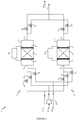
- the treatment unit 1 is provided with a biogas supply pipe to be treated 11 , a sweep gas supply pipe 12 , which is preferably air, and a supply pipe for flushing gas 13 which is preferably biogas previously treated in the unit.
- a biogas supply pipe to be treated 11 a sweep gas supply pipe 12 , which is preferably air
- a supply pipe for flushing gas 13 which is preferably biogas previously treated in the unit.
- Each supply duct is divided to supply the two devices 2 and 2 ' and valves 16 , 17 , 18 , 19 , 20 and 21 are placed on the supply ducts to select the gas flows to be introduced into the two devices.
- the treatment unit 1 is provided with an outlet pipe for the treated biogas 14 and an outlet pipe for the other gaseous effluents 15 , in particular the purging gas used and the rinsing gas used.
- Each outlet conduit brings together the effluents from the two devices 2 and 2 ' and valves 22 , 23 , 24 and 25 are placed on the outlet
- the treatment unit 1 can be operated according to the diagram shown in the figure 2 : this represents the succession of parallel processing cycles on devices 2 and 2 ' .
- the relative durations of the stages are only given by way of example.
- the device 2 begins with a filtration step (a).
- a filtration step (a) the valves 16 and 22 are open while the valves 17 , 18 and 23 are closed.
- the filtration chamber 3 is supplied with biogas arriving via the conduit 11 . Passing through the filter 6 , the contaminating siloxane compounds are adsorbed. The treated biogas is recovered at the outlet of chamber 3 via line 14 .
- Step (a) is carried out for a period Ta.
- step (a) When step (a) is finished, the valves 16 and 22 are closed.
- the treatment cycle continues immediately with a step (b1) of regenerating the filter 6 .
- the valves 17 and 23 are open.
- a direct electric current is circulated in said filter 6 connected to the electrodes 7 and 8 thanks to the current generator 9 .
- the filter 6 heats up.
- An air flow is used as the purge gas. It is introduced into the filtration chamber 3 through the supply duct 12 using the blower 10 . Under the effect of heating and sweeping, the siloxane contaminants are desorbed from the filter 6 and the sweep gas used is discharged through line 15 .
- Step (b1) is carried out for a period Tb at the end of which the filter 6 is considered to be regenerated.
- step (b1) When step (b1) is finished, the valve 17 is closed and the electric current passing through the filter 6 is stopped.
- the treatment cycle continues immediately with a step (c) of rinsing the filter 6 .
- the filter 6 and the filtration chamber 3 contain air.
- the valve 18 is open.
- a stream of biogas previously treated, coming for example from line 14 is introduced into the filtration chamber 3 through the supply duct 13 .
- the flushing gas used, containing air, is discharged through line 15 .
- Step (c) is carried out for a period Tc.
- step (c) the valves 18 and 23 are closed.
- the device 2 is ready to start again a filtration phase (a).
- the device 2 ' is operated in the same way as the device 2 using the valves 19 , 20 , 21 , 24 and 25 , but with a time lag of the phases.
- the device 2 ' begins a phase (b1) of regeneration, and when the device 2 ends the phase (a) of filtration to pass to the phase (b1) of regeneration, it is the device 2 ' which begins a filtration phase (a).
- there is permanently one of the two devices which is in phase (a) of filtration which makes it possible to ensure a continuous treatment of the biogas arriving via the supply conduit 11 .
- the activated carbon fabric used is that sold by the company Carbon Cloth International under the name Zorflex® Knitted Cloth FM30K.
- thermogravimetric analyzer (SETSYS Evolution or TG-DSC 111 from Setaram). Each sample was subjected to a temperature gradient of 10 ° C per minute between 20 ° C and 105 ° C, then to a plateau at 105 ° C for 30 minutes in order to desorb the water contained in the pores of the tissue, and finally at a temperature gradient of 10 ° C per minute up to 300 ° C.
- the variation in the mass of the sample was measured using a microbalance. The variation of mass as a function of time has been studied as a function of temperature. The desorption temperature is taken at the maximum desorption speed.
- Table 1 presents the results obtained for various siloxanes: Table 1 Siloxane Boiling point (° C) Maximum desorption speed temperature (° C) Desorption rate (mg.g -1 .min -1 ) Hexamethyldisiloxane 101 110 -7.9 Decamethyltetrasiloxane 194 180 -4.2 Dodecamethylpentasiloxane 230 200 -5.2 Octamethylcyclotetracyloxane 175 170 -5.8 Decamethylcyclopentasiloxane 211 200 -5.3
- the temperatures for which the desorption rate is the greatest are between 110 ° C. and 200 ° C.
- the desorption rates are all of the same order of magnitude, between 4 mg.g -1 .min -1 and 8 mg.g -1 .min -1 .
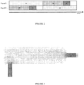
- the gas flow velocity distribution is shown on the figure 3 : white corresponds to a speed of 0 m / s, then the higher the speed, the darker the color, up to black which corresponds to a speed of 20 m / s.
- the treatment device comprises two filters in parallel, each filter being a circular filter 30 cm in diameter and 75 cm long.
- This filter is made up of 20 layers of Zorflex FM 30 K activated carbon fabric (Calgon Carbon).
- the biogas treated in this example comes from a purification station with a flow rate of 500 Nm 3 / h, and contains siloxanes at a concentration of 100 mg / Nm 3 .
- the linear speed of the biogas for this filtering passage surface is 20 cm / s and the pressure drops amount to 4 mbar.
- the input biogas pressure is 0.1 bar (relative pressure).
- the filtration step (a) is carried out for a period Ta of one hour, at an adsorption temperature of 35 ° C.
- the concentration of siloxanes leaving the treatment device is less than 0.1 mg / Nm 3 .
- the regeneration step (b1) is carried out for a duration Tb of 15 minutes, at a temperature of 250 ° C.
- An air flow at a pressure of 0.05 bar (relative pressure) is used as the purging gas.
- This example describes the optional step (b2) of thermal destruction of the sweep gas at the outlet of the filtration chamber. More specifically, it illustrates the difference in biogas consumption necessary to regenerate the filter, that is to say to burn the sweeping gas, between a regeneration process using Joule heating combined with a sweeping gas flow ( case of the present invention), and a regeneration method using only a flow of hot air, without Joule effect.
- the sweeping gas stream to be removed comes from a biogas treatment test in accordance with Example 3 above.
- the purge gas flow is a depleted air flow (approximately 10% oxygen by volume) circulating at a flow rate of 25 m 3 / h.
- This flow is then destroyed at the outlet of the filtration chamber, by a very lean gas burner (of the FLOX® type with flameless oxidation) which operates with a methane percentage equal to 2.5% by volume.
- the crude biogas containing 60% methane, the volume of crude biogas to be added for the operation of the burner is 1.1 m 3 / h.
- the filter is regenerated 12 times with a regeneration time of 30 minutes. The total consumption of biogas for regeneration is therefore 6.4 m 3 / day.
- a regeneration process using hot air only requires a regeneration rate of 250 m 3 / h.
- the hot air flow is then destroyed by a lean gas burner which operates with a percentage of methane equal to 12.5% by volume.
- the raw biogas containing 60% methane, the volume of raw biogas to be added for the operation of the burner is 59.5 m 3 / h.
- the filter is regenerated only once with a regeneration time of 2.5 hours. The total consumption of biogas for regeneration is therefore 148.8 m 3 / day.
Landscapes
- Chemical & Material Sciences (AREA)
- Engineering & Computer Science (AREA)
- Analytical Chemistry (AREA)
- General Chemical & Material Sciences (AREA)
- Oil, Petroleum & Natural Gas (AREA)
- Chemical Kinetics & Catalysis (AREA)
- Separation Of Gases By Adsorption (AREA)
- Solid-Sorbent Or Filter-Aiding Compositions (AREA)
Priority Applications (1)
| Application Number | Priority Date | Filing Date | Title |
|---|---|---|---|
| PL14784282T PL3043884T3 (pl) | 2013-09-13 | 2014-09-12 | Regeneracyjny sposób usuwania związków siloksanowych z biogazu |
Applications Claiming Priority (2)
| Application Number | Priority Date | Filing Date | Title |
|---|---|---|---|
| FR1358865A FR3010719B1 (fr) | 2013-09-13 | 2013-09-13 | Procede regeneratif d'elimination des composes siloxanes dans du biogaz |
| PCT/FR2014/052266 WO2015036711A1 (fr) | 2013-09-13 | 2014-09-12 | Procede regeneratif d'elimination des composes siloxanes dans du biogaz |
Publications (2)
| Publication Number | Publication Date |
|---|---|
| EP3043884A1 EP3043884A1 (fr) | 2016-07-20 |
| EP3043884B1 true EP3043884B1 (fr) | 2020-07-01 |
Family
ID=49510394
Family Applications (1)
| Application Number | Title | Priority Date | Filing Date |
|---|---|---|---|
| EP14784282.7A Active EP3043884B1 (fr) | 2013-09-13 | 2014-09-12 | Procede regeneratif d'elimination des composes siloxanes dans du biogaz |
Country Status (6)
| Country | Link |
|---|---|
| US (1) | US9962643B2 (pl) |
| EP (1) | EP3043884B1 (pl) |
| ES (1) | ES2818592T3 (pl) |
| FR (1) | FR3010719B1 (pl) |
| PL (1) | PL3043884T3 (pl) |
| WO (1) | WO2015036711A1 (pl) |
Families Citing this family (8)
| Publication number | Priority date | Publication date | Assignee | Title |
|---|---|---|---|---|
| US20160303507A1 (en) * | 2015-04-17 | 2016-10-20 | Generon Igs, Inc. | Gas separation membrane module with integrated filter |
| JP6772470B2 (ja) * | 2016-01-29 | 2020-10-21 | 東洋紡株式会社 | 有機溶剤処理装置 |
| KR102267445B1 (ko) * | 2016-02-15 | 2021-06-18 | 질리카 페어파렌스테크니크 게엠베하 | 오염물이 함유된 가스를 처리하기 위한 장치 및 방법 |
| DE102017001114B4 (de) * | 2016-02-15 | 2022-08-18 | Silica Verfahrenstechnik Gmbh | Vorrichtung und Verfahren zum Behandeln eines mit Schadstoffen belasteten Gases |
| US11029292B2 (en) * | 2016-04-08 | 2021-06-08 | Mls Acq, Inc. | Method for identification and quantification of siloxanes in gaseous stream |
| US10890555B2 (en) * | 2017-08-30 | 2021-01-12 | Technion Research And Development Foundation Ltd. | Robust GMOs |
| CA3166283A1 (en) | 2020-01-29 | 2021-08-05 | Shazam S. Williams | Siloxane removal systems and methods |
| WO2021174349A1 (en) * | 2020-03-02 | 2021-09-10 | Granitefuel Engineering Inc. | Siloxane treatment vessel regeneration |
Citations (1)
| Publication number | Priority date | Publication date | Assignee | Title |
|---|---|---|---|---|
| US20120024157A1 (en) * | 2010-07-29 | 2012-02-02 | ADSORPTECH Inc. | Method to clean impurities from bio-gas using adsorption |
Family Cites Families (14)
| Publication number | Priority date | Publication date | Assignee | Title |
|---|---|---|---|---|
| JPH089822B2 (ja) * | 1988-02-26 | 1996-01-31 | 株式会社ペトカ | 炭素繊維不織布の製造方法 |
| JPH06142432A (ja) * | 1992-11-11 | 1994-05-24 | Masahiro Hori | 吸着化学物質の脱着法 |
| US5899187A (en) * | 1996-07-11 | 1999-05-04 | Jenbacher Energiesysteme Aktiengesellschaft | Engine arrangement |
| US5912423A (en) * | 1997-01-23 | 1999-06-15 | Calgon Carbon Corporation | Method and means for purifying air with a regenerable carbon cloth sorbent |
| DE19828593A1 (de) * | 1998-04-07 | 1999-10-14 | Andreas Noack | Adsorptionsvorrichtung zur Fluidreinigung ausgestattet mit Mitteln zur Regeneration des adsorbierenden Materials |
| US6364936B1 (en) * | 2000-05-15 | 2002-04-02 | The Board Of Trustees Of The University Of Illinois | Selective sorption and desorption of gases with electrically heated activated carbon fiber cloth element |
| DE10032385B4 (de) | 2000-07-06 | 2005-07-14 | M + W Zander Facility Engineering Gmbh | Verfahren zur Regenerierung von mit organischen Substanzen beladenen elektrisch leitfähigen Adsorbentien |
| CA2484967A1 (en) | 2001-12-19 | 2003-06-26 | Mcgill University | Adsorption of contaminants from gaseous stream and in situ regeneration of sorbent |
| US7393381B2 (en) * | 2003-06-19 | 2008-07-01 | Applied Filter Technology, Inc. | Removing siloxanes from a gas stream using a mineral based adsorption media |
| US20070068386A1 (en) * | 2005-09-23 | 2007-03-29 | Mitariten Michael J | Landfill gas upgrading process |
| US8080095B2 (en) * | 2006-05-10 | 2011-12-20 | The Board Of Trustees Of The University Of Illinois | Steady state tracking desorption system and method |
| US20130137567A1 (en) | 2011-05-27 | 2013-05-30 | Applied Filter Technology, Inc. | Device to clean siloxanes from biogas, and a method of regenerating the same including electric swing adsorption |
| US9023755B2 (en) * | 2012-12-18 | 2015-05-05 | Cabot Corporation | Siloxane removal from gases using lignite-enhanced activated carbons and adsorbent media used therefor |
| US9039807B2 (en) * | 2013-06-18 | 2015-05-26 | Guild Associates | Regenerative adsorption process for removal of silicon-containing contaminants from process gas using a neutral adsorbent media |
-
2013
- 2013-09-13 FR FR1358865A patent/FR3010719B1/fr active Active
-
2014
- 2014-09-12 EP EP14784282.7A patent/EP3043884B1/fr active Active
- 2014-09-12 WO PCT/FR2014/052266 patent/WO2015036711A1/fr not_active Ceased
- 2014-09-12 ES ES14784282T patent/ES2818592T3/es active Active
- 2014-09-12 PL PL14784282T patent/PL3043884T3/pl unknown
- 2014-09-12 US US14/916,880 patent/US9962643B2/en active Active
Patent Citations (1)
| Publication number | Priority date | Publication date | Assignee | Title |
|---|---|---|---|---|
| US20120024157A1 (en) * | 2010-07-29 | 2012-02-02 | ADSORPTECH Inc. | Method to clean impurities from bio-gas using adsorption |
Also Published As
| Publication number | Publication date |
|---|---|
| ES2818592T3 (es) | 2021-04-13 |
| US9962643B2 (en) | 2018-05-08 |
| FR3010719A1 (fr) | 2015-03-20 |
| WO2015036711A1 (fr) | 2015-03-19 |
| US20160206990A1 (en) | 2016-07-21 |
| EP3043884A1 (fr) | 2016-07-20 |
| FR3010719B1 (fr) | 2017-02-24 |
| PL3043884T3 (pl) | 2021-04-06 |
Similar Documents
| Publication | Publication Date | Title |
|---|---|---|
| EP3043884B1 (fr) | Procede regeneratif d'elimination des composes siloxanes dans du biogaz | |
| TWI494302B (zh) | 純化乙炔之方法 | |
| CA2475445A1 (fr) | Procede de traitement d'un melange gazeux comprenant de l'hydrogene et du sulfure d'hydrogene | |
| EP1120149A1 (fr) | Procédé de purification d'un gaz par adsorption des impuretés sur plusieurs charbons actifs | |
| WO2009010690A2 (fr) | Procede de purification d'un gaz contenant du co2 | |
| EP2334603B1 (fr) | Procede de traitement d'eau incluant un recyclage de charbon actif en poudre | |
| FR2999448A1 (fr) | Procede de captage du co2 par adsorption | |
| FR3009203A1 (fr) | Procede de captation d'un metal lourd contenu dans un gaz humide integrant une pompe a chaleur pour chauffer le gaz introduit dans une masse de captation | |
| CA2693038A1 (fr) | Procede pour eliminer le mercure d'un gaz contenant du co2 et de l'oxygene | |
| FR3035337B1 (fr) | Procede de purification d'un gaz comprenant du methane | |
| JP3627100B2 (ja) | 消化ガスの精製方法 | |
| EP0532814B1 (fr) | Dispositif de traitement de fluide, au moyen d'une structure d'adsorption à feuilles superposées espacées,et régénération par effet Joule | |
| EP2794069B1 (fr) | Procédé et dispositif pour améliorer la captation du so2 dans des gaz de cuves d'électrolyse | |
| FR2836058A1 (fr) | Procede de separation d'un melange gazeux et installation de mise en oeuvre d'un tel procede | |
| LU85425A1 (fr) | Procede d'obtention de substances organiques en partant de gaz,par adsorption suivie d'une detoxication par combustion | |
| BE1016691A3 (fr) | Procede et dispositif de traitement de gaz. | |
| JP2004337745A (ja) | ガス精製装置 | |
| EP3755446A1 (fr) | Système et procédé pour le traitement de gaz | |
| WO2013057387A1 (fr) | Procédé de captage d'un composé contenu dans un gaz par adsorption sur lit vertical | |
| JP5579032B2 (ja) | バイオマスガス化システム及びバイオマスガス化ガスの精製方法 | |
| FR2974519A1 (fr) | Procede de purification d'un gaz humide contant des cov par adsorption faisant appel a une phase de regeneration par chauffage par micro-ondes | |
| FR3016535A1 (fr) | Procede integre thermiquement d'elimination du dioxyde de carbone dans du biogaz | |
| FR2458308A1 (fr) | Procede et installation pour eliminer des composants ou polluants oxydables de gaz et en particulier de l'air | |
| CN108714372A (zh) | 用于煤化工废水的处理方法 | |
| JP2014198323A (ja) | メタンガスの濃縮方法 |
Legal Events
| Date | Code | Title | Description |
|---|---|---|---|
| PUAI | Public reference made under article 153(3) epc to a published international application that has entered the european phase |
Free format text: ORIGINAL CODE: 0009012 |
|
| 17P | Request for examination filed |
Effective date: 20160318 |
|
| AK | Designated contracting states |
Kind code of ref document: A1 Designated state(s): AL AT BE BG CH CY CZ DE DK EE ES FI FR GB GR HR HU IE IS IT LI LT LU LV MC MK MT NL NO PL PT RO RS SE SI SK SM TR |
|
| AX | Request for extension of the european patent |
Extension state: BA ME |
|
| DAX | Request for extension of the european patent (deleted) | ||
| STAA | Information on the status of an ep patent application or granted ep patent |
Free format text: STATUS: EXAMINATION IS IN PROGRESS |
|
| 17Q | First examination report despatched |
Effective date: 20190808 |
|
| GRAP | Despatch of communication of intention to grant a patent |
Free format text: ORIGINAL CODE: EPIDOSNIGR1 |
|
| STAA | Information on the status of an ep patent application or granted ep patent |
Free format text: STATUS: GRANT OF PATENT IS INTENDED |
|
| INTG | Intention to grant announced |
Effective date: 20200131 |
|
| GRAS | Grant fee paid |
Free format text: ORIGINAL CODE: EPIDOSNIGR3 |
|
| GRAA | (expected) grant |
Free format text: ORIGINAL CODE: 0009210 |
|
| STAA | Information on the status of an ep patent application or granted ep patent |
Free format text: STATUS: THE PATENT HAS BEEN GRANTED |
|
| AK | Designated contracting states |
Kind code of ref document: B1 Designated state(s): AL AT BE BG CH CY CZ DE DK EE ES FI FR GB GR HR HU IE IS IT LI LT LU LV MC MK MT NL NO PL PT RO RS SE SI SK SM TR |
|
| REG | Reference to a national code |
Ref country code: CH Ref legal event code: EP Ref country code: AT Ref legal event code: REF Ref document number: 1285617 Country of ref document: AT Kind code of ref document: T Effective date: 20200715 |
|
| REG | Reference to a national code |
Ref country code: IE Ref legal event code: FG4D Free format text: LANGUAGE OF EP DOCUMENT: FRENCH |
|
| REG | Reference to a national code |
Ref country code: DE Ref legal event code: R096 Ref document number: 602014067260 Country of ref document: DE |
|
| REG | Reference to a national code |
Ref country code: LT Ref legal event code: MG4D |
|
| PG25 | Lapsed in a contracting state [announced via postgrant information from national office to epo] |
Ref country code: BG Free format text: LAPSE BECAUSE OF FAILURE TO SUBMIT A TRANSLATION OF THE DESCRIPTION OR TO PAY THE FEE WITHIN THE PRESCRIBED TIME-LIMIT Effective date: 20201001 |
|
| REG | Reference to a national code |
Ref country code: NL Ref legal event code: MP Effective date: 20200701 |
|
| REG | Reference to a national code |
Ref country code: AT Ref legal event code: MK05 Ref document number: 1285617 Country of ref document: AT Kind code of ref document: T Effective date: 20200701 |
|
| PG25 | Lapsed in a contracting state [announced via postgrant information from national office to epo] |
Ref country code: FI Free format text: LAPSE BECAUSE OF FAILURE TO SUBMIT A TRANSLATION OF THE DESCRIPTION OR TO PAY THE FEE WITHIN THE PRESCRIBED TIME-LIMIT Effective date: 20200701 Ref country code: SE Free format text: LAPSE BECAUSE OF FAILURE TO SUBMIT A TRANSLATION OF THE DESCRIPTION OR TO PAY THE FEE WITHIN THE PRESCRIBED TIME-LIMIT Effective date: 20200701 Ref country code: GR Free format text: LAPSE BECAUSE OF FAILURE TO SUBMIT A TRANSLATION OF THE DESCRIPTION OR TO PAY THE FEE WITHIN THE PRESCRIBED TIME-LIMIT Effective date: 20201002 Ref country code: NO Free format text: LAPSE BECAUSE OF FAILURE TO SUBMIT A TRANSLATION OF THE DESCRIPTION OR TO PAY THE FEE WITHIN THE PRESCRIBED TIME-LIMIT Effective date: 20201001 Ref country code: AT Free format text: LAPSE BECAUSE OF FAILURE TO SUBMIT A TRANSLATION OF THE DESCRIPTION OR TO PAY THE FEE WITHIN THE PRESCRIBED TIME-LIMIT Effective date: 20200701 Ref country code: HR Free format text: LAPSE BECAUSE OF FAILURE TO SUBMIT A TRANSLATION OF THE DESCRIPTION OR TO PAY THE FEE WITHIN THE PRESCRIBED TIME-LIMIT Effective date: 20200701 Ref country code: LT Free format text: LAPSE BECAUSE OF FAILURE TO SUBMIT A TRANSLATION OF THE DESCRIPTION OR TO PAY THE FEE WITHIN THE PRESCRIBED TIME-LIMIT Effective date: 20200701 Ref country code: CZ Free format text: LAPSE BECAUSE OF FAILURE TO SUBMIT A TRANSLATION OF THE DESCRIPTION OR TO PAY THE FEE WITHIN THE PRESCRIBED TIME-LIMIT Effective date: 20200701 Ref country code: PT Free format text: LAPSE BECAUSE OF FAILURE TO SUBMIT A TRANSLATION OF THE DESCRIPTION OR TO PAY THE FEE WITHIN THE PRESCRIBED TIME-LIMIT Effective date: 20201102 |
|
| PG25 | Lapsed in a contracting state [announced via postgrant information from national office to epo] |
Ref country code: LV Free format text: LAPSE BECAUSE OF FAILURE TO SUBMIT A TRANSLATION OF THE DESCRIPTION OR TO PAY THE FEE WITHIN THE PRESCRIBED TIME-LIMIT Effective date: 20200701 Ref country code: RS Free format text: LAPSE BECAUSE OF FAILURE TO SUBMIT A TRANSLATION OF THE DESCRIPTION OR TO PAY THE FEE WITHIN THE PRESCRIBED TIME-LIMIT Effective date: 20200701 Ref country code: IS Free format text: LAPSE BECAUSE OF FAILURE TO SUBMIT A TRANSLATION OF THE DESCRIPTION OR TO PAY THE FEE WITHIN THE PRESCRIBED TIME-LIMIT Effective date: 20201101 |
|
| PG25 | Lapsed in a contracting state [announced via postgrant information from national office to epo] |
Ref country code: NL Free format text: LAPSE BECAUSE OF FAILURE TO SUBMIT A TRANSLATION OF THE DESCRIPTION OR TO PAY THE FEE WITHIN THE PRESCRIBED TIME-LIMIT Effective date: 20200701 |
|
| REG | Reference to a national code |
Ref country code: DE Ref legal event code: R119 Ref document number: 602014067260 Country of ref document: DE |
|
| REG | Reference to a national code |
Ref country code: ES Ref legal event code: FG2A Ref document number: 2818592 Country of ref document: ES Kind code of ref document: T3 Effective date: 20210413 |
|
| PG25 | Lapsed in a contracting state [announced via postgrant information from national office to epo] |
Ref country code: DK Free format text: LAPSE BECAUSE OF FAILURE TO SUBMIT A TRANSLATION OF THE DESCRIPTION OR TO PAY THE FEE WITHIN THE PRESCRIBED TIME-LIMIT Effective date: 20200701 Ref country code: EE Free format text: LAPSE BECAUSE OF FAILURE TO SUBMIT A TRANSLATION OF THE DESCRIPTION OR TO PAY THE FEE WITHIN THE PRESCRIBED TIME-LIMIT Effective date: 20200701 Ref country code: RO Free format text: LAPSE BECAUSE OF FAILURE TO SUBMIT A TRANSLATION OF THE DESCRIPTION OR TO PAY THE FEE WITHIN THE PRESCRIBED TIME-LIMIT Effective date: 20200701 Ref country code: SM Free format text: LAPSE BECAUSE OF FAILURE TO SUBMIT A TRANSLATION OF THE DESCRIPTION OR TO PAY THE FEE WITHIN THE PRESCRIBED TIME-LIMIT Effective date: 20200701 Ref country code: MC Free format text: LAPSE BECAUSE OF FAILURE TO SUBMIT A TRANSLATION OF THE DESCRIPTION OR TO PAY THE FEE WITHIN THE PRESCRIBED TIME-LIMIT Effective date: 20200701 |
|
| REG | Reference to a national code |
Ref country code: CH Ref legal event code: PL |
|
| PLBE | No opposition filed within time limit |
Free format text: ORIGINAL CODE: 0009261 |
|
| STAA | Information on the status of an ep patent application or granted ep patent |
Free format text: STATUS: NO OPPOSITION FILED WITHIN TIME LIMIT |
|
| PG25 | Lapsed in a contracting state [announced via postgrant information from national office to epo] |
Ref country code: AL Free format text: LAPSE BECAUSE OF FAILURE TO SUBMIT A TRANSLATION OF THE DESCRIPTION OR TO PAY THE FEE WITHIN THE PRESCRIBED TIME-LIMIT Effective date: 20200701 |
|
| 26N | No opposition filed |
Effective date: 20210406 |
|
| REG | Reference to a national code |
Ref country code: BE Ref legal event code: MM Effective date: 20200930 |
|
| PG25 | Lapsed in a contracting state [announced via postgrant information from national office to epo] |
Ref country code: LU Free format text: LAPSE BECAUSE OF NON-PAYMENT OF DUE FEES Effective date: 20200912 Ref country code: SK Free format text: LAPSE BECAUSE OF FAILURE TO SUBMIT A TRANSLATION OF THE DESCRIPTION OR TO PAY THE FEE WITHIN THE PRESCRIBED TIME-LIMIT Effective date: 20200701 |
|
| PG25 | Lapsed in a contracting state [announced via postgrant information from national office to epo] |
Ref country code: DE Free format text: LAPSE BECAUSE OF NON-PAYMENT OF DUE FEES Effective date: 20210401 |
|
| PG25 | Lapsed in a contracting state [announced via postgrant information from national office to epo] |
Ref country code: LI Free format text: LAPSE BECAUSE OF NON-PAYMENT OF DUE FEES Effective date: 20200930 Ref country code: IE Free format text: LAPSE BECAUSE OF NON-PAYMENT OF DUE FEES Effective date: 20200912 Ref country code: SI Free format text: LAPSE BECAUSE OF FAILURE TO SUBMIT A TRANSLATION OF THE DESCRIPTION OR TO PAY THE FEE WITHIN THE PRESCRIBED TIME-LIMIT Effective date: 20200701 Ref country code: BE Free format text: LAPSE BECAUSE OF NON-PAYMENT OF DUE FEES Effective date: 20200930 Ref country code: CH Free format text: LAPSE BECAUSE OF NON-PAYMENT OF DUE FEES Effective date: 20200930 |
|
| PG25 | Lapsed in a contracting state [announced via postgrant information from national office to epo] |
Ref country code: TR Free format text: LAPSE BECAUSE OF FAILURE TO SUBMIT A TRANSLATION OF THE DESCRIPTION OR TO PAY THE FEE WITHIN THE PRESCRIBED TIME-LIMIT Effective date: 20200701 Ref country code: MT Free format text: LAPSE BECAUSE OF FAILURE TO SUBMIT A TRANSLATION OF THE DESCRIPTION OR TO PAY THE FEE WITHIN THE PRESCRIBED TIME-LIMIT Effective date: 20200701 Ref country code: CY Free format text: LAPSE BECAUSE OF FAILURE TO SUBMIT A TRANSLATION OF THE DESCRIPTION OR TO PAY THE FEE WITHIN THE PRESCRIBED TIME-LIMIT Effective date: 20200701 |
|
| PG25 | Lapsed in a contracting state [announced via postgrant information from national office to epo] |
Ref country code: MK Free format text: LAPSE BECAUSE OF FAILURE TO SUBMIT A TRANSLATION OF THE DESCRIPTION OR TO PAY THE FEE WITHIN THE PRESCRIBED TIME-LIMIT Effective date: 20200701 |
|
| PGFP | Annual fee paid to national office [announced via postgrant information from national office to epo] |
Ref country code: GB Payment date: 20240923 Year of fee payment: 11 |
|
| PGFP | Annual fee paid to national office [announced via postgrant information from national office to epo] |
Ref country code: PL Payment date: 20240822 Year of fee payment: 11 |
|
| PGFP | Annual fee paid to national office [announced via postgrant information from national office to epo] |
Ref country code: IT Payment date: 20240909 Year of fee payment: 11 |
|
| PGFP | Annual fee paid to national office [announced via postgrant information from national office to epo] |
Ref country code: ES Payment date: 20241007 Year of fee payment: 11 |
|
| PGFP | Annual fee paid to national office [announced via postgrant information from national office to epo] |
Ref country code: FR Payment date: 20250717 Year of fee payment: 12 |