EP3042678A1 - Outer tube for syringe and pre-filled syringe - Google Patents
Outer tube for syringe and pre-filled syringe Download PDFInfo
- Publication number
- EP3042678A1 EP3042678A1 EP14842197.7A EP14842197A EP3042678A1 EP 3042678 A1 EP3042678 A1 EP 3042678A1 EP 14842197 A EP14842197 A EP 14842197A EP 3042678 A1 EP3042678 A1 EP 3042678A1
- Authority
- EP
- European Patent Office
- Prior art keywords
- cap
- female luer
- female
- main body
- syringe
- Prior art date
- Legal status (The legal status is an assumption and is not a legal conclusion. Google has not performed a legal analysis and makes no representation as to the accuracy of the status listed.)
- Granted
Links
Images




Classifications
-
- A—HUMAN NECESSITIES
- A61—MEDICAL OR VETERINARY SCIENCE; HYGIENE
- A61M—DEVICES FOR INTRODUCING MEDIA INTO, OR ONTO, THE BODY; DEVICES FOR TRANSDUCING BODY MEDIA OR FOR TAKING MEDIA FROM THE BODY; DEVICES FOR PRODUCING OR ENDING SLEEP OR STUPOR
- A61M5/00—Devices for bringing media into the body in a subcutaneous, intra-vascular or intramuscular way; Accessories therefor, e.g. filling or cleaning devices, arm-rests
- A61M5/178—Syringes
- A61M5/28—Syringe ampoules or carpules, i.e. ampoules or carpules provided with a needle
-
- A—HUMAN NECESSITIES
- A61—MEDICAL OR VETERINARY SCIENCE; HYGIENE
- A61M—DEVICES FOR INTRODUCING MEDIA INTO, OR ONTO, THE BODY; DEVICES FOR TRANSDUCING BODY MEDIA OR FOR TAKING MEDIA FROM THE BODY; DEVICES FOR PRODUCING OR ENDING SLEEP OR STUPOR
- A61M39/00—Tubes, tube connectors, tube couplings, valves, access sites or the like, specially adapted for medical use
- A61M39/20—Closure caps or plugs for connectors or open ends of tubes
-
- A—HUMAN NECESSITIES
- A61—MEDICAL OR VETERINARY SCIENCE; HYGIENE
- A61M—DEVICES FOR INTRODUCING MEDIA INTO, OR ONTO, THE BODY; DEVICES FOR TRANSDUCING BODY MEDIA OR FOR TAKING MEDIA FROM THE BODY; DEVICES FOR PRODUCING OR ENDING SLEEP OR STUPOR
- A61M5/00—Devices for bringing media into the body in a subcutaneous, intra-vascular or intramuscular way; Accessories therefor, e.g. filling or cleaning devices, arm-rests
- A61M5/178—Syringes
- A61M5/31—Details
- A61M5/3129—Syringe barrels
-
- A—HUMAN NECESSITIES
- A61—MEDICAL OR VETERINARY SCIENCE; HYGIENE
- A61M—DEVICES FOR INTRODUCING MEDIA INTO, OR ONTO, THE BODY; DEVICES FOR TRANSDUCING BODY MEDIA OR FOR TAKING MEDIA FROM THE BODY; DEVICES FOR PRODUCING OR ENDING SLEEP OR STUPOR
- A61M5/00—Devices for bringing media into the body in a subcutaneous, intra-vascular or intramuscular way; Accessories therefor, e.g. filling or cleaning devices, arm-rests
- A61M5/178—Syringes
- A61M5/31—Details
- A61M5/3129—Syringe barrels
- A61M5/3135—Syringe barrels characterised by constructional features of the proximal end
-
- A—HUMAN NECESSITIES
- A61—MEDICAL OR VETERINARY SCIENCE; HYGIENE
- A61M—DEVICES FOR INTRODUCING MEDIA INTO, OR ONTO, THE BODY; DEVICES FOR TRANSDUCING BODY MEDIA OR FOR TAKING MEDIA FROM THE BODY; DEVICES FOR PRODUCING OR ENDING SLEEP OR STUPOR
- A61M5/00—Devices for bringing media into the body in a subcutaneous, intra-vascular or intramuscular way; Accessories therefor, e.g. filling or cleaning devices, arm-rests
- A61M5/178—Syringes
- A61M5/31—Details
- A61M5/315—Pistons; Piston-rods; Guiding, blocking or restricting the movement of the rod or piston; Appliances on the rod for facilitating dosing ; Dosing mechanisms
- A61M5/31501—Means for blocking or restricting the movement of the rod or piston
- A61M5/31505—Integral with the syringe barrel, i.e. connected to the barrel so as to make up a single complete piece or unit
-
- A—HUMAN NECESSITIES
- A61—MEDICAL OR VETERINARY SCIENCE; HYGIENE
- A61M—DEVICES FOR INTRODUCING MEDIA INTO, OR ONTO, THE BODY; DEVICES FOR TRANSDUCING BODY MEDIA OR FOR TAKING MEDIA FROM THE BODY; DEVICES FOR PRODUCING OR ENDING SLEEP OR STUPOR
- A61M5/00—Devices for bringing media into the body in a subcutaneous, intra-vascular or intramuscular way; Accessories therefor, e.g. filling or cleaning devices, arm-rests
- A61M5/178—Syringes
- A61M5/31—Details
- A61M2005/3103—Leak prevention means for distal end of syringes, i.e. syringe end for mounting a needle
- A61M2005/3104—Caps for syringes without needle
-
- A—HUMAN NECESSITIES
- A61—MEDICAL OR VETERINARY SCIENCE; HYGIENE
- A61M—DEVICES FOR INTRODUCING MEDIA INTO, OR ONTO, THE BODY; DEVICES FOR TRANSDUCING BODY MEDIA OR FOR TAKING MEDIA FROM THE BODY; DEVICES FOR PRODUCING OR ENDING SLEEP OR STUPOR
- A61M5/00—Devices for bringing media into the body in a subcutaneous, intra-vascular or intramuscular way; Accessories therefor, e.g. filling or cleaning devices, arm-rests
- A61M5/178—Syringes
- A61M5/31—Details
- A61M2005/3103—Leak prevention means for distal end of syringes, i.e. syringe end for mounting a needle
- A61M2005/3106—Plugs for syringes without needle
Definitions
- the present invention relates to a syringe barrel and a pre-filled syringe.
- a pre-filled syringe which is previously filled with a liquid drug or the like (see, for example, JapanesePatentNo. 4156791 ).
- Thepre-filled syringe needs to prevent the liquid drug or the like contained therein from leaking through its distal end opening before its use, particularly during transport. Therefore, a cap is attached to the syringe barrel of the pre-filled syringe to liquid-tightly seal the cylinder tip (syringe distal end opening) of the main body of the barrel.
- pre-filled syringe has a female luer (female fitting part) configured as the cylinder tip of the barrel main body.
- the pre-filled syringe (FM syringe) having a female luer is connected to, for example, a pre-filled syringe (ML syringe) that has a male luer (male fitting part) provided at its distal end and is previously filled with a liquid (e.g., normal saline).
- ML syringe pre-filled syringe
- the liquid drug in the FM syringe is sucked into the ML syringe and mixed with the liquid within the ML syringe to prepare a desired liquid drug.
- the pre-filled syringe having a female luer has a cap attached to the female luer, and the cap has a sealing part made of an elastic material.
- the sealing part is configured so that part of the sealing part corresponding to the volume of the male luer to be inserted is inserted into the female luer in a state where the cap is attached to the female luer.
- the sealing part has an outer periphery that is in close contact with the inner periphery of the female luer to provide liquid sealing performance that is its original function.
- the present invention is directed to a syringe barrel including: an barrel main body having, at a distal end thereof, a female luer that a male luer is insertable into and connectable to; and a cap that is detachably attached to the female luer to close an opening of the female luer, wherein the female luer includes a female-side fixing part that detachably fixes the cap, wherein the cap includes an insertion part inserted into the female luer, a sealing part that seals the opening of the female luer, and a cap-side fixing part that is detachably engaged with the female-side fixing part, and wherein in a state where the cap is fixed to the female luer by engagement between the female-side fixing part and the cap-side fixing part, the insertion part is spaced apart from an inner periphery of the female luer, and the sealing part is in close contact with a distal end surface of the female luer along
- the syringe barrel has a gap provided between the inner periphery of the female luer and the insertion part, which makes it possible to sterilize the inner periphery of the female luer in its production process. More specifically, when the syringe barrel is subjected to sterilization in its production process, high-temperature steam or liquid is in contact with the inner periphery of the female luer, whichmakes it possible to sterilize the inner periphery. Further, the insertion part of the cap is inserted into the female luer, which makes it possible to prevent the leakage of a drug at the time when a male luer is connected.
- the opening of the female luer is liquid-tightly sealed not by close contact between the inner periphery of the female luer and the outer periphery of the insertion part but by close contact between the sealing part and the distal end surface of the female luer along the entire circumference of the opening. Therefore, the syringe barrel according to the present invention can ensure liquid tightness at the time when the cap is not opened, can prevent the leakage of a drug at the time when a male luer is connected, and can sterilize the inner periphery of the female luer.
- the cap may include an elastic member having the sealing part, and a main body that supports the elastic member, has the cap-side fixing part, and is harder than the elastic member, and a pressing part may be formed at a distal end of the female luer so as to project in a distal direction to press the sealing part along the entire circumference of the opening in a state where the cap is fixed to the female luer.
- the pressing part presses the sealing part along the entire circumference of the opening, and therefore the pressing part and the sealing part are in sufficiently close contact with each other so that excellent sealing performance is achieved.
- the elastic member may include a cylindrical part that has a closed proximal end and forms the insertion part, and a flange part that surrounds a distal end opening of the cylindrical part and forms the sealing part.
- the insertion part and the sealing part are integrally molded, and therefore only one portion is required to be sealed, and excellent sealing performance can be achieved by a simple structure.
- the female-side fixing part and the cap-side fixing part may be threadedly engageable with each other.
- the main body may have an anti-rotation part that prevents relative rotation of the elastic member with respect to the main body.
- the anti-rotation part may be inserted into the cylindrical part and engaged with an inner periphery of the cylindrical part.
- the relative rotation of the elastic member with respect to the main body can be effectively prevented by a simple structure, and in addition, the elastic member can be stably supported by the anti-rotation part.
- the anti-rotation part may have a columnar part that extends along an axial direction of the cap and a rib that projects from an outer periphery of the columnar part outward and extends in the axial direction.
- the main body may have a cap-side engagement part
- the female luer may have a female-side engagement part that is engaged with the cap-side engagement part to prevent loosening of the cap in a state where the female-side fixing part and the cap-side fixing part are threadedly engaged with each other.
- an engagement force between the cap-side engagement part and the female-side engagement part may be larger than a rotation force that exerts on the cap based on an elastic force of the elastic member.
- the main body may include a cylindrical cover that covers an outer periphery of the female luer
- the cap-side engagement part may be formed at a proximal end part of the cover
- the female luer may have a projection that is formed to radially project from a outer periphery of a proximal end part of the female luer and constitutes the female-side engagement part.
- a proximal-side inner periphery of the cover may have a small distance part that constitutes the cap-side engagement part, wherein a distance from a rotation axis of the cap at the time when the cap is threadedly engaged with the female luer to the small distance part is smaller than a distance from the rotation axis to an outer end of the projection, wherein the small distance part of the cover is formed in a production process of the syringe barrel by expanding a part of the proximal-side inner periphery of the cover outward by the projection and thereby deforming other part of the proximal-side inner periphery inward, and is engaged with the projection to prevent loosening of the cap in a state where the cap is attached to the female luer.
- the small distance part of the cover that is engaged with the projection to prevent the loosening of the cap is obtained as a result of deformation of the proximal-side inner periphery caused by a force received from the projection, and therefore the projection and the cover establish an accurate positional relationship when engaged with each other. Therefore, it is not necessary to align a threaded engagement structure between the cap and the cylinder tip with the projection, and therefore it is possible to easily obtain a rattle-free structure for preventing the loosening of the cap.
- the present invention is also directed to a pre-filled syringe including; the syringe barrel, a gasket that is slidably movable in the barrel main body in a liquid tight manner, and a drug filled in a filling chamber defined by the barrel main body, the gasket, and the cap.
- the syringe barrel and the pre-filled syringe according to the present invention can ensure liquid tightness at the time when the cap is not opened, can prevent the leakage of a drug at the time when a male luer is connected, and can sterilize the inner periphery of the female luer.
- Fig. 1 is a perspective view of a pre-filled syringe 10 according to one embodiment of the present invention.
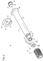
- Fig. 2 is an exploded perspective view of the pre-filled syringe 10.
- Fig. 3 is a longitudinal sectional view of the pre-filled syringe 10.
- Fig. 4 is an enlarged longitudinal sectional view of the distal end of the pre-filled syringe 10.
- the pre-filled syringe 10 includes, as its main components, a cylindrical barrel main body 12 having a cylinder tip 22, a cap 14 that seals the cylinder tip 22 of the barrel main body 12, a gasket 16 that is slidably movable in the barrel main body 12 in a liquid tight manner, and a drug M filled in a filling chamber 13 formed in the barrel main body 12.
- the barrel main body 12 and the cap 14 constitute a syringe barrel 18.
- the barrel main body 12 has a body part 20 constituting the main part of the barrel main body 12, a cylinder tip 22 provided at the distal end of the body part 20, and a flange 24 formed to radially project outward from the proximal end of the body part 20.
- the cylinder tip 22 projects from the distal end of the barrel main body 12 in the distal direction so as to have a diameter smaller than that of the barrel main body 12.
- the cylinder tip 22 constitutes a female luer 23 into and to which a male luer 82 can be inserted and connected (see Fig. 8B ).
- the female luer 23 has a tapered inner periphery 23a (see Fig. 4 ) whose inner diameter increases toward the distal direction.
- a female-side fixing part 26 is provided to detachably fix the cap 14.
- the female-side fixing part 26 is a threaded engagement part (male screw) that is threadedly engageable with the cap 14.
- the female-side fixing part 26 shown in the drawings includes two engagement projections 27 that project in opposite directions with respect to the axis of the barrel main body 12.
- a ring-shaped pressing part 28 is provided which projects in the distal direction and extends in the circumferential direction around the axis of the barrel main body 12. The pressing part 28 presses a sealing part 39 that will be described later along the entire circumference of an opening 23b in a state where the cap 14 is fixed (attached) to the female luer 23.
- a projection 30 is provided to prevent the loosening of the cap 14 before use.
- a pair of projections 30 is provided which projects in opposite directions with respect to the axis of the barrel main body 12.
- the projections 30 are engaged with a cap-side engagement part 51 in a proximal-side inner periphery 50a of a cover 50 that will be described later (see Fig. 7 ). In this way, the projections 30 prevent the loosening of threaded engagement between the cap 14 and the female luer 23 .
- the projections 30 constitute a female-side engagement part 31 that is engaged with the cap-side engagement part 51 to prevent the loosening of the cap 14 in a state where the female-side fixing part 26 and a cap-side fixing part 44 are threadedly engaged with each other. It is to be noted that the function of the projection 30 to prevent the loosening of the cap 14 will be described again after description of the specific structure of the cap 14.
- the projections 30 are provided near the proximal end of the female luer 23, that is, provided at a position slightly spaced apart from a distal end surface 20a of the body part 20 in the distal direction (see Fig. 4 ).
- Examples of a constituent material of the barrel main body 12 having such a structure as described above include various resins such as polypropylene, polyethylene, polystyrene, polyamide, polycarbonate, polyvinyl chloride, poly-(4-methylpentene-1), acrylic resins, acrylonitrile-butadiene-styrene copolymers, polyesters such as polyethyleneterephthalate, andcyclicpolyolefins.
- resins such as polypropylene and cyclic polyolef ins are preferred for ease of molding and heat resistance.
- the cap 14 has an elastic member 32 that seals the opening 23b of the female luer 23, and a main body 34 that supports the elastic member 32.
- the opening 23b of the female luer 23 is liquid-tightly sealed with the cap 14 (see Fig. 2 ) so that the drug M does not leak through the opening 23b.
- the elastic member 32 is placed in the main body 34 (in a recess 42 that will be described later).
- the elastic member 32 has a cylindrical part 36 that has an open distal end and a closed proximal end and extends in the axial direction of the cap 14, and a flange part 38 that surrounds the distal end opening of the cylindrical part 36 and radially projects outward.
- the elastic member 32 is formed by integrally molding the cylindrical part 36 and the flange part 38 without gap between them.
- the cylindrical part 36 constitutes an insertion part 37 inserted into the female luer 23.
- the flange part 38 constitutes a sealing part 39 that seals the opening 23b of the female luer 23.
- Examples of a constituent material of the elastic member 32 include: various rubber materials such as natural rubber, butyl rubber, isoprene rubber, butadiene rubber, styrene-butadiene rubber, and silicone rubber; various thermoplastic elastomers such as polyurethane-based thermoplastic elastomers, polyester-based thermoplastic elastomers, polyamide-based thermoplastic elastomers, olefin-based thermoplastic elastomers, and styrene-based thermoplastic elastomers; and mixtures of two or more of them.
- various rubber materials such as natural rubber, butyl rubber, isoprene rubber, butadiene rubber, styrene-butadiene rubber, and silicone rubber
- various thermoplastic elastomers such as polyurethane-based thermoplastic elastomers, polyester-based thermoplastic elastomers, polyamide-based thermoplastic elastomers, olefin-based thermoplastic elastomers, and
- the insertion part 37 is spaced apart from the inner periphery 23a of the female luer 23 in a state where the cap 14 is fixed (attached) to the female luer 23. That is, the outer diameter of the insertion part 37 is smaller than the inner diameter of the female luer 23, and therefore an annular gap 40 is created between the inner periphery 23a of the female luer 23 and the outer periphery of the insertion part 37.
- the annular gap 40 is in communication with the inside of the body part 20 of the barrel main body 12.
- the sealing part 39 is in close contact with the distal end surface (pressing part 28) of the female luer 23 along the entire circumference of the opening 23b of the female luer 23, and is dented in the distal direction by pressing with the pressing part 28 in the distal direction.
- the sealing part 39 has a flat proximal end surface in its natural state (in a state where the sealing part 39 is not pressed with the pressing part 28).
- the main body 34 of the cap 14 is made of a material harder than the elastic member 32 (e.g., a material mentioned above as an example of the constituent material of the barrel main body 12), and has a recess 42 opened in the proximal direction.
- the main body 34 has a cap-side fixing part 44 that is threadedly engaged with the female-side fixing part 26, a supporting part 46 that supports the flange part 38 of the elastic member 32, an anti-rotation part 48 that prevents the relative rotation of the elastic member 32 with respect to the main body 34, and a cover 50 that covers the outer periphery of the female luer 23.
- the outer periphery of the main body 34 has surface irregularities formed to prevent slipping at the time when the cap 14 is rotated.
- the cap-side fixing part 44 is formed to project from the inner periphery of the cover 50.
- the cap-side fixing part 44 is a female screw 45 that is threadedly engaged with the female-side fixing part 26 (see Fig. 5 ).
- the supporting part 46 is formed by the bottom of the recess 42, and the flange part 38 of the elastic member 32 is inserted and held in the supporting part 46.
- the flange part 38 has an outer diameter larger than the diameter of the outer periphery of the supporting part 46, and is fitted to the supporting part 46. This makes it possible to eliminate the necessity to integrally mold the elastic member 32 and the main body 34 or to fix the elastic member 32 to the main body 34 with an adhesive or the like and therefore to simplify a production process.
- the anti-rotation part 48 projects from the center of the bottom of the recess 42 in the proximal direction along the axis of the cap 14.
- the free end of the supporting part 46 (the proximal end of the cap 14) is positioned on the distal side of a proximal opening 34a of the main body 34.
- engagement (fixation) between the cap 14 and the female luer 23 is not limited to the above-described threaded engagement.
- the cap-side fixing part 44 may be a cover-side engagement projection provided to project inward from the inner periphery of the cover 50
- the female-side fixing part 26 may be a female-side engagement projection provided to project outward from the outer periphery of the female luer 23 so that the cover-side engagement projection is caught on the proximal side of the female-side engagement projection.
- the cover 50 is elastically deformed and the cover-side engagement projection overpasses the female-side engagement projection so that the cap 14 can be separated from the female luer 23.
- the anti-rotation part 48 is inserted into the cylindrical part 36 of the elastic member 32 and engaged with the inner periphery 36a of the cylindrical part 36.
- the anti-rotation part 48 has a columnar part 52 that extends in the axial direction of the cap 14, and a plurality of ribs 54 that project outward from the outer periphery of the columnar part 52 and extend in the axial direction.
- the ribs 54 are provided at intervals on the outer periphery of the columnar part 52 in the circumferential direction.
- Fig. 6 that is a cross-sectional view taken along the line VI-VI in Fig. 4
- the anti-rotation part 48 having the ribs 54 is fitted to the cylindrical part 36 in a state where the inner periphery 36a of the cylindrical part 36 of the elastic member 32 is elastically deformed by the anti-rotation part 48 so as to have surface irregularities. This makes it possible to prevent the relative rotation of the elastic member 32 with respect to the main body 34.
- the number of the ribs 54 provided on the columnar part 52 may be only one. Also in this case, the effect of preventing the relative rotation of the elastic member 32 with respect to the main body 34 can be obtained.
- the inner periphery 36a of the cylindrical part 36 of the elastic member 32 may have one or more inner ribs that extend in the axial direction and radially project inward. When the number of the inner ribs is two or more, the inner ribs may be provided at intervals in the circumferential direction.
- the inner rib (s) of the elastic member 32 is(are) engaged with the ribs 54 of the columnar part 52, which makes it possible to further enhance the effect of preventing the relative rotation of the elastic member 32 with respect to the main body 34.
- the anti-rotation part 48 is not limited to one having the ribs 54, and may have any structure as long as its cross-section perpendicular to the axial direction has a non-circular profile.
- the anti-rotation part 48 whose cross-sectional profile is non-circular can prevent the relative rotation of the elastic member 32 with respect to the main body 34.
- the anti-rotation part 48 maybe a rib formed on the inner periphery of the supporting part 46 to radially project inward.
- the anti-rotation part 48 is fitted to the flange part 38 in a state where the outer periphery of the flange part 38 of the elastic member 32 is elastically deformed by the rib so as to have surface irregularities. This makes it possible to prevent the relative rotation of the elastic member 32 with respect to the main body 34.
- the inner periphery of the supporting part 46 and the outer periphery of the flange part 38 may have polygonal cross-sectional shapes that correspond with each other to prevent the relative rotation of the elastic member 32 with respect to the main body 34.
- the anti-rotation part 48 constitutes the inner periphery of the supporting part 46.
- the anti-rotation part 48 may be provided, at the distal end of the flange part 38, as a projection to be engaged with a recess provided at the bottom (distal end) of the supporting part 46. It is to be noted that in a case where the anti-rotation part 48 other than the columnar part 52 is provided, the columnar part 52 may be omitted from the main body 34.
- the cover 50 extends from a base 56 of the cap 14 in the proximal direction.
- the cover 50 covers almost the entire length of the female luer 23, and the proximal end of the cover 50 is in proximity to the distal end surface 20a of the body part 20 of the barrel main body 12.
- the cover 50 is thinner and is more likely to deform as compared to the female luer 23 having the projections 30.
- An engagement force between the cover 50 and the projections 30 is larger than a rotation force exerting on the cap 14 based on the elastic force of the elastic member 32 (specifically, the sealing part 39).
- the proximal-side inner periphery 50a of the cover 50 has small distance parts 50b.
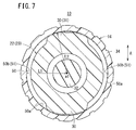
- a distance L1 from a rotation axis a1 of the cap 14 to each of the small distance parts 50b at the time when the cap 14 is threadedly engaged with the cylinder tip 22 is smaller than a distance L2 from the rotation axis a1 to the outer end of each of the projections 30.
- the cross-sectional shape of the proximal-side inner periphery 50a of the cover 50 is not an accurate circle but an ellipse (an ellipse having a long axis in a direction represented by an arrow A in Fig. 7 ) .
- a part of the proximal-side inner periphery 50a of the cover 50 is radially expanded outward by the projections 30 provided in the female luer 23, and therefore the other part of the proximal-side inner periphery 50a is deformed inward so that the small distance parts 50b are formed.
- the proximal-side inner periphery 50a of the cover 50 has a circular cross-section perpendicular to the axis of the cover 50 before the production of the syringe barrel 18, and therefore the small distance parts 50b are provided to be opposed to each other with respect to the rotation axis a1. Therefore, the proximal-side inner periphery 50a of the cover 50 has an elliptical cross-sectional shape.
- the proximal-side inner periphery 50a of the cover 50 has a circular (almost true circular) cross-sectional shape represented by a chain double-dashed line in Fig. 7 at the time when the main body 34 is produced.
- the small distance parts 50b are provided so that the proximal-side inner periphery 50a of the cover 50 has an elliptical cross-sectional shape.
- a non-circular structure formed by the proximal-side inner periphery 50a of the cover 50 is engaged with a non-circular structure formed by the two projections 30, and therefore the function of preventing the loosening of the cap 14 with respect to female luer 23 delivers.
- the small distance parts 50b of the cover 50 are engaged with the projections 30 (female-side engagement part 31), and therefore the cap 14 is hard to loosen. That is, the small distance parts 50b constitute the cap-side engagement part 51 that is engaged with the female-side engagement part 31 in a state where the female-side fixing part 26 is threadedly engaged with the cap-side fixing part 44.
- the pre-filled syringe 10 is subjected to autoclave sterilization in its production process in a state where the cap 14 is attached to the barrel main body 12. Therefore, the cap 14 is thermally deformed by high heat associated with autoclave sterilization so that the deformation of the proximal-side inner periphery 50a of the cover 50 by the projections 30 is established. As a result, the proximal-side inner periphery 50a of the cover 50 is more reliably provided with the small distance parts 50b and has an elliptical cross-sectional shape.
- proximal-side inner periphery 50a of the cover 50 can be provided with the small distance parts 50b and has an elliptical cross-sectional shape.
- An engagement force between the small distance parts 50b of the cover 50 and the projections 30 is larger than a rotation force exerting on the cap 14 based on the elastic force of the elastic member 32 (specifically, the sealing part 39). This makes it possible to reliably prevent the loosening of the cap 14.
- the number of the projections 30 provided in the female luer 23 may be only one.
- the proximal-side inner periphery 50a of the cover 50 can have a non-circular cross-sectional shape during sterilization in the production process.
- the projections 30 may be arranged at, for example, 60° intervals.
- the proximal-side inner periphery 50a of the cover 50 can have a cross-sectional shape close to a triangle (a triangular cross-sectional shape having round corners) during sterilization in the production process.
- the projection 30 may be formed so that its outer edge has an elliptical shape surrounding the entire outer circumference of the female luer 23.
- the length of the short axis of the elliptical projection 30 is smaller than the diameter of the proximal-side inner periphery 50a of the cover 50, and the length of the long axis of the elliptical projection 30 is larger than the diameter of the proximal-side inner periphery 50a of the cover 50.
- the gasket 16 is inserted into the barrel main body 12.
- the gasket 16 has a distal end surface 60, and the distal end surface 60 has a tapered shape that becomes thinner toward the distal end.
- the gasket 16 has two ormore ring-shaped sealing projections (in Fig. 3 , two ring-shaped sealing projections) 62 formed on its outer periphery at intervals in the axial direction. In a state where the gasket 16 is inserted in the barrel main body 12, the sealing projections 62 are in close contact with the inner periphery of the barrel main body 12. Therefore, the gasket 16 is slidably movable in the barrel main body 12 in a liquid tight manner.
- the gasket 16 may have a coating film formed on its outer surface to reduce sliding resistance against the inner periphery of the barrel main body 12.
- a coating film include fluorine-based resins such as polytetrafluoroethylene (PTFE), tetrafluoroethylene ⁇ perfluoroalkylvinyl ether copolymer resin (PFA), tetrafluoroethylene ⁇ hexafluoropropylene copolymer (FEP), polychlorotrifluoroethylene (PCTFE), and polyvinylidene fluoride (PVDF), polyparaxylylene, and diamond-like carbon.
- PTFE polytetrafluoroethylene
- PFA perfluoroalkylvinyl ether copolymer resin
- FEP tetrafluoroethylene ⁇ hexafluoropropylene copolymer
- PCTFE polychlorotrifluoroethylene
- PVDF polyvinylidene fluoride
- the inner periphery of the barrel main body 12 or the outer periphery of the gasket 16 may be coated with a liquid lubricant (e.g., silicone oil).
- a liquid lubricant e.g., silicone oil
- the gasket 16 has a fitting recess 64 provided to have an opening at its proximal end.
- the fitting recess 64 has a male screw 66 formed on its inner periphery.
- the fitting recess 64 can be threadedly engaged with the distal end of a plunger not shown.
- Examples of a constituent material of the gasket 16 include those mentioned above as examples of the constituent material of the elastic member 32 of the cap 14.
- a gasket stopper 68 is detachably attached to the proximal end (flange 24) of the barrel main body 12 to prevent the gasket 16 from coming out of the barrel main body 12 in the proximal direction.
- the gasket stopper 68 has a stopper plate 72 having a communication path 70 that penetrates therethrough in the axial direction and has a diameter smaller than the inner diameter of the body part 20 of the barrel main body 12, and a semi-circular engagement plate 74 that is laterally opened to be engaged with the flange 24 of the barrel main body 12.
- the body part 20 of the barrel main body 12 is inserted into the engagement plate 74, and the flange 24 is inserted between the stopper plate 72 and the engagement plate 74 so that the gasket stopper 68 is attached to the proximal end of the barrel main body 12.
- the drug M will be described which is filled in the filling chamber 13 defined by the barrel main body 12, the gasket 16, and the cap 14.
- the drug M may be of any type, such as a powdered drug, a freeze-dried drug, a solid drug, or a liquid drug, as long as the drug M can be dissolved in or diluted with a medical liquid L (specifically, a solvent such as normal saline) filled in a dilution-side pre-filled syringe 80 (see Fig. 8B and Fig. 8C ).
- Examples of the drugM include protein preparations, antitumor agents, vitamin preparations (multivitamin preparations), various amino acids, antithrombotic agents such as heparin, insulin, antibiotics, pain relievers, cardiotonic agents, intravenous anesthetics, medical anesthetics, antiparkinsonian agents, anti-ulcer agents, adrenal corticosteroids, and antiarrhythmic agents.
- the syringe barrel 18 and the pre-filled syringe 10 according to the present embodiment basically have such structures as described above. Hereinbelow, their functions and effects will be described.
- the gap 40 is provided between the inner periphery 23a of the female luer 23 and the insertion part 37 of the cap 14. Therefore, as will be described below, the inner periphery 23a of the female luer 23 can be sterilized.
- autoclave sterilization high-pressure steam sterilization
- the pre-filled syringe 10 assembled as shown in Fig. 1 and Fig. 3 is subjected to sterilization.
- not only these areas but also the inner surface of the syringe constituting the filling chamber 13 is sterilized.
- the filling chamber 13 is filled with the drug M, the inner surface of the syringe that is in contact with the drug M heated at high temperature associated with sterilization is sterilized. Further, even when a space not filled with the drug is present in the filling chamber 13, the inner surface of the syringe is sterilized with the steam of the drug M (in a case where the drug M is liquid). In this case, as shown in Fig.
- the annular gap 40 is created between the inner periphery 23a of the female luer 23 and the outer periphery of the insertion part 37 of the cap 14, the inner periphery 23a of the female luer 23 is effectively sterilized by the entry of the high-temperature drug M or the steam of the drug M into the gap 40.
- the syringe barrel 18 is subjected to sterilization before the filling of the drug M and the insertion of the gasket 16. Specifically, the syringe barrel 18 is assembled by attaching the cap 14 to the barrel main body 12, and is then subjected to autoclave sterilization. In this case, since the annular gap 40 is created between the inner periphery 23a of the female luer 23 and the insertion part 37 of the cap 14, the inner periphery 23a of the female luer 23 is also effectively sterilized by the entry of high-temperature steam into the gap 40.
- the drug M is filled into the barrel main body 12 of the sterilized syringe barrel 18 in a sterilized space (e.g., in an isolator), and the gasket 16 is inserted into the barrel main body 12, and the gasket stopper 68 is finally attached.
- a sterilized space e.g., in an isolator
- the cross-sectional shape of the proximal-side inner periphery 50a of the cover 50 is formed by thermal deformation of the cover 50 caused by heat at the time of the above-described autoclave sterilization. That is, the cross-sectional shape of the proximal-side inner periphery 50a of the cover 50 before autoclave sterilization is a circle (almost true circle) as shown by a virtual line in Fig. 7 . However, at the time of autoclave sterilization, the cover 50 that is thinner and is more likely to deform than the female luer 23 is softened by heat and thermally deformed in a state where the cover 50 receives a pressing force applied by the projections 30 outward in a direction represented by the arrow A.
- the proximal-side inner periphery 50a of the cover 50 after sterilization has an elliptical cross-sectional shape fitted to the two projections 30 provided in a lock adaptor 100. That is, irrespective to the positional relationship in the circumferential direction between the projections 30 and the cover 50, the projections 30 expand a part of the cover 50 outward, and therefore the other part of the proximal-side inner periphery 50a is reliably deformed inward so that the small distance parts 50b are formed. Therefore the function of preventing the loosening of the cap 14 with respect to the female luer 23 delivers.
- the pre-filled syringe 10 before use is in a state where the cap 14 is attached to the female luer 23 of the barrel main body 12.
- the sealing part 39 made of an elastic material is in close contact with the distal end surface of the female luer 23 along the entire circumference of the opening 23b, and therefore the opening 23b of the female luer 23 is liquid-tightly sealed.
- the pressing part 28 provided at the distal end of the female luer 23 presses the sealing part 39 along the entire circumference of the opening 23b, and therefore the pressing part 28 and the sealing part 39 are in sufficiently close contact with each other so that excellent sealing performance is achieved.
- this embodiment has a structure in which the projections 30 are provided on the outer periphery of a proximal end part of the female luer 23 to prevent the loosening of the cap 14 before use.
- the small distance parts 50b of the main body 34 (cover 50) having a non-circular shape (elliptical shape) formed by thermal deformation at the time of sterilization are engaged with the projections 30 provided on the outer periphery of a proximal end part of the female luer 23 with high accuracy. Therefore, the loosening of the cap 14 before use is effectively prevented. Specifically, when the cap 14 is tried to be rotated in a direction to loosen threaded engagement between the cap 14 and the female luer 23 in the presence of the small distance parts 50b, resistance is generated to cause the small distance parts 50b to overpass the projections 30. As a result, the cap 14 is hard to loosen. In this way, the small distance parts 50b function as a loosening-resistance generator.
- the cap 14 When the pre-filled syringe 10 is used, as shown in Fig. 8A , the cap 14 is opened. Specifically, in a state where the female luer 23 is directed upward, the cap 14 is rotated in a predetermined direction around the barrel main body 12 to release engagement (threaded engagement) between the cap-side fixing part 44 and the female-side fixing part 26 to remove the cap 14 from the female luer 23. In this case, when a rotation force equal to or larger than a predetermined rotation force is applied to the cap 14, the proximal side of the main body 34 (cover 50) is elastically deformed, which allows the cap 14 to be rotated and removed.
- the projections 30 are provided on the outer periphery of a proximal end part of the female luer 23, engagement between the projections 30 and the main body 34 is released only by slightly rotating the cap 14. That is, the projections 30 and the main body 34 are engaged only in the initial stage of the operation of opening the cap 14, and thereafter the cap 14 can be rotated with a little operating force thereafter. Therefore, the cap 14 is easily opened.
- the elastic member 32 is rotated together with the main body 34 at the time of the operation of opening the cap 14. For this reason, the elastic member 32 is reliably separated from the pressing part 28 of the female luer 23 by rotating the cap 14. Therefore, the elastic member 32 does not remain on the female luer 23 side due to sticking to the pressing part 28 of the female luer 23.
- the pre-filled syringe 80 filled with the medical liquid L is connected to the pre-filled syringe 10.
- the male luer 82 provided as a cylinder tip in the pre-filled syringe 80 is inserted into and connected to the female luer 23 of the pre-filled syringe 10.
- the drug M does not leak from the barrel main body 12 at the time when the male luer 82 is connected.
- the medical liquid L filled in the pre-filled syringe 80 may be a liquid for dissolving a drug, such as distilled water for injection or normal saline, or a liquid drug that contains a drug (e.g., a vitamin preparation or a mineral) and can dissolve or dilute the drug M filled in the pre-filled syringe 10. It is to be noted that the medical liquid L is not limited to one previously filled in the pre-filled syringe 80 as in the case of this embodiment, and may be sucked into an empty syringe from a vial or the like in a necessary amount when required.
- a plunger (not shown) of the pre-filled syringe 80 is pulled in the proximal direction to suck the drug M from the barrel main body 12 into the pre-filled syringe 80 so that the drug M is mixed with and dissolved in or diluted with the medical liquid L in the pre-filled syringe 80.
- so-called pumping may be performed in such a manner that the drug M is once sucked into the pre-filled syringe 80, and then the resulting mixture is returned to the barrel main body 12 and again sucked into the pre-filled syringe 80.
- the gasket stopper 68 is attached to the proximal end (flange 24) of the barrel main body 12, the gasket 16 does not come out of the barrel main body 12 in the proximal direction, which makes it possible to prevent the leakage of the mixture from the proximal end of the barrel main body 12.
- the gasket stopper 68 has the communication path 70 formed to penetrate therethrough in the axial direction, the inside of the barrel main body 12 located on the proximal side of the gasket 16 and the outside of the barrel main body 12 communicate with each other. Therefore, the sliding of the gasket 16 in the barrel main body 12 during pumping is not interfered with.
- the communication path 70 is not limited to a hole penetrating through the gasket stopper 68 in the axial direction as long as the communication path 70 allows the inside of the barrel main body 12 located on the proximal side of the gasket 16 and the outside of the barrel main body 12 to communicate with each other.
- a projection may be formed on the distal end surface of the stopper plate 72 of the gasket stopper 68 to provide, as the communication path 70, a gap between the stopper plate 72 and the proximal end surface of the barrel main body 12.
- the gap 40 is provided between the inner periphery 23a of the female luer 23 and the insertion part 37, which makes it possible to sterilize the inner periphery 23a of the female luer 23. More specifically, when the syringe barrel 18 is subjected to sterilization in its production process, high-temperature steam or liquid comes into contact with the inner periphery 23a of the female luer 23, which makes it possible to sterilize the inner periphery 23a. Further, the insertion part 37 of the cap 14 is inserted into the female luer 23, which prevents the leakage of the drug M at the time when the male luer 82 is connected.
- the opening 23b of the female luer 23 is liquid-tightly sealed not by close contact between the inner periphery 23a of the female luer 23 and the outer periphery of the insertion part 37 but by close contact between the sealing part 39 and the distal end surface of the female luer 23 along the entire circumference of the opening 23b. Therefore, the syringe barrel 18 according to the present invention can ensure liquid tightness at the time when the cap is not opened, can prevent the leakage of the drug at the time when the male luer is connected, and can sterilize the inner periphery 23a of the female luer 23.
- the pressing part 28 presses the sealing part 39 along the entire circumference of the opening 23b, the pressing part 28 and the sealing part 39 are in sufficiently close contact with each other so that excellent sealing performance is achieved.
- the insertion part 37 and the sealing part 39 are integrally formed as the elastic member 32, only one portion is required to be sealed, and therefore excellent sealing performance can be achieved by a simple structure.
- the main body 34 of the cap 14 has the anti-rotation part 48 that prevents the relative rotation of the elastic member 32 with respect to the main body 34.
- This structure makes it possible to, when the cap 14 is rotated and removed from the female luer 23, prevent the elastic member 32 from remaining on the female luer 23 side due to sticking to the pressing part 28. Further, since the anti-rotation part 48 is inserted into the cylindrical part 36 and engaged with the inner periphery 36a of the cylindrical part 36, the relative rotation of the elastic member 32 with respect to the main body 34 can be effectively prevented by a simple structure, and in addition, the anti-rotation part 48 can stably support the elastic member 32.
- the anti-rotation part 48 since the anti-rotation part 48 has the columnar part 52 that extends along the axial direction of the cylindrical part 36 and the ribs 54 that project from the outer periphery of the columnar part 52 outward and extend in the axial direction, the relative rotation of the elastic member 32 with respect to the main body 34 can be more effectively prevented.
- the female luer 23 is provided with the female-side engagement part 31, and the cap 14 is provided with the cap-side engagement part 51 (see Fig. 7 ), the loosening of the cap 14 can be appropriately prevented.
- the cap-side engagement part 51 is formed at the proximal end of the cover 50, and the female luer 23 has the projections 30 that are formed to radially project from the outer periphery of a proximal end part of the female luer 23 and constitute the female-side engagement part 31, engagement between the projections 30 and the cover 50 is released only by s lightly rotating the cap 14, and therefore the cap 14 can be easily opened.
- the two projections 30 are provided which project in opposite directions with respect to the axis of the female luer 23.
- the projections 30 are engaged with the cover 50 at two points opposite to each other, which is highly effective at preventing the loosening of the cap 14 and makes it possible to hold the cap 14 coaxially with the female luer 23.
- the cap-side engagement part 51 and the female-side engagement part 31 are not limited to those of the above-described embodiment as long as the loosening of the cap 14 threadedly engaged with the female luer 23 can be prevented.
- a loosening-preventing projection may be formed in the groove of the female screw 45 of the cap 14, which is engaged with the engagement projections constituting the female-side fixing part 26 when the cap-side fixing part 44 and the female-side fixing part 26 are threadedly engaged with each other.
- the cap-side engagement part 51 and the female-side engagement part 31 are constituted from the loosening-preventing projection and the engagement projections, respectively.
- cap-side engagement part 51 may be a groove or projection formed in or on the proximal-side inner periphery 50a of the cover 50
- the female-side engagement part 31 may be a projection that is formed to radially project from the outer periphery of a proximal end part of the female luer 23 so as to be engaged with the proximal-side groove or projection of the cover 50.
- cap-side engagement part 51 may be a recess or projection formed in or on the proximal-side inner periphery 50a of the cover 50
- the female-side engagement part 31 may be a projection that is formed to radially project from the outer periphery of a proximal end part of the female luer 23 so as to be engaged with the recess or projection of the proximal-side inner periphery 50a of the cover 50.
- cap-side engagement part 51 may be a recess or projection formed in or on the proximal end surface of the cover 50
- the female-side engagement part 31 may be a projection that is formed to radially project from the outer periphery of a proximal end part of the female luer 23 so as to be engaged with the recess or projection of the proximal end surface of the cover 50.
Landscapes
- Health & Medical Sciences (AREA)
- Heart & Thoracic Surgery (AREA)
- Hematology (AREA)
- Anesthesiology (AREA)
- Biomedical Technology (AREA)
- Engineering & Computer Science (AREA)
- Life Sciences & Earth Sciences (AREA)
- Animal Behavior & Ethology (AREA)
- General Health & Medical Sciences (AREA)
- Public Health (AREA)
- Veterinary Medicine (AREA)
- Vascular Medicine (AREA)
- Pulmonology (AREA)
- Infusion, Injection, And Reservoir Apparatuses (AREA)
Abstract
Description
- The present invention relates to a syringe barrel and a pre-filled syringe.
- As one of conventional syringes, a pre-filled syringe is known which is previously filled with a liquid drug or the like (see, for example,
JapanesePatentNo. 4156791 - One example of such a pre-filled syringe has a female luer (female fitting part) configured as the cylinder tip of the barrel main body. The pre-filled syringe (FM syringe) having a female luer is connected to, for example, a pre-filled syringe (ML syringe) that has a male luer (male fitting part) provided at its distal end and is previously filled with a liquid (e.g., normal saline). Then, in a state where the FM syringe is connected to the ML syringe, the liquid drug in the FM syringe is sucked into the ML syringe and mixed with the liquid within the ML syringe to prepare a desired liquid drug.
- The pre-filled syringe having a female luer has a cap attached to the female luer, and the cap has a sealing part made of an elastic material. In order to prevent the occurrence of liquid leakage when a male luer is connected, the sealing part is configured so that part of the sealing part corresponding to the volume of the male luer to be inserted is inserted into the female luer in a state where the cap is attached to the female luer. Further, the sealing part has an outer periphery that is in close contact with the inner periphery of the female luer to provide liquid sealing performance that is its original function.
- Meanwhile, in the process of producing the pre-filled syringe having afemaleluer,sterilization (high-pressure steam sterilization) is performed to achieve a predetermined cleanliness level. In terms of production, performing high-pressure steam sterilization in a state where the cap is attached to the female luer of the barrel main body is efficient. In this case, however, the inner periphery of the female luer cannot be sterilized because the sealing part of the cap is in close contact with the inner periphery of the female luer.
- In consideration of such a problem, it is an object of the present invention to provide a syringe barrel and a pre-filled syringe that can ensure liquid tightness at the time when a cap is not opened, can prevent the leakage of a drug at the time when a male luer is connected, and can sterilize the inner periphery of a female luer.
- In order to achieve the above obj ect, the present invention is directed to a syringe barrel including: an barrel main body having, at a distal end thereof, a female luer that a male luer is insertable into and connectable to; and a cap that is detachably attached to the female luer to close an opening of the female luer, wherein the female luer includes a female-side fixing part that detachably fixes the cap, wherein the cap includes an insertion part inserted into the female luer, a sealing part that seals the opening of the female luer, and a cap-side fixing part that is detachably engaged with the female-side fixing part, and wherein in a state where the cap is fixed to the female luer by engagement between the female-side fixing part and the cap-side fixing part, the insertion part is spaced apart from an inner periphery of the female luer, and the sealing part is in close contact with a distal end surface of the female luer along an entire circumference of the opening.
- The syringe barrel has a gap provided between the inner periphery of the female luer and the insertion part, which makes it possible to sterilize the inner periphery of the female luer in its production process. More specifically, when the syringe barrel is subjected to sterilization in its production process, high-temperature steam or liquid is in contact with the inner periphery of the female luer, whichmakes it possible to sterilize the inner periphery. Further, the insertion part of the cap is inserted into the female luer, which makes it possible to prevent the leakage of a drug at the time when a male luer is connected. Further, in the case of the structure according to the present invention, the opening of the female luer is liquid-tightly sealed not by close contact between the inner periphery of the female luer and the outer periphery of the insertion part but by close contact between the sealing part and the distal end surface of the female luer along the entire circumference of the opening. Therefore, the syringe barrel according to the present invention can ensure liquid tightness at the time when the cap is not opened, can prevent the leakage of a drug at the time when a male luer is connected, and can sterilize the inner periphery of the female luer.
- In the syringe barrel, the cap may include an elastic member having the sealing part, and a main body that supports the elastic member, has the cap-side fixing part, and is harder than the elastic member, and a pressing part may be formed at a distal end of the female luer so as to project in a distal direction to press the sealing part along the entire circumference of the opening in a state where the cap is fixed to the female luer. In the case of this structure, the pressing part presses the sealing part along the entire circumference of the opening, and therefore the pressing part and the sealing part are in sufficiently close contact with each other so that excellent sealing performance is achieved.
- In the syringe barrel, the elastic member may include a cylindrical part that has a closed proximal end and forms the insertion part, and a flange part that surrounds a distal end opening of the cylindrical part and forms the sealing part. In the case of this structure, the insertion part and the sealing part are integrally molded, and therefore only one portion is required to be sealed, and excellent sealing performance can be achieved by a simple structure.
- In the above syringe barrel, the female-side fixing part and the cap-side fixing part may be threadedly engageable with each other.
- In the above syringe barrel, the main body may have an anti-rotation part that prevents relative rotation of the elastic member with respect to the main body. This structure makes it possible to, when the cap is rotated to be removed from the female luer, prevent the elastic member from remaining on the female luer side due to sticking to the pressing part.
- In the above syringe barrel, the anti-rotation part may be inserted into the cylindrical part and engaged with an inner periphery of the cylindrical part. In the case of this structure, the relative rotation of the elastic member with respect to the main body can be effectively prevented by a simple structure, and in addition, the elastic member can be stably supported by the anti-rotation part.
- In the above syringe barrel, the anti-rotation part may have a columnar part that extends along an axial direction of the cap and a rib that projects from an outer periphery of the columnar part outward and extends in the axial direction. This structure makes it possible to more effectively prevent the relative rotation of the elastic member with respect to the main body.
- In the above syringe barrel, the main body may have a cap-side engagement part, and the female luer may have a female-side engagement part that is engaged with the cap-side engagement part to prevent loosening of the cap in a state where the female-side fixing part and the cap-side fixing part are threadedly engaged with each other. This structure makes it possible to prevent the loosening of the cap.
- In the above syringe barrel, an engagement force between the cap-side engagement part and the female-side engagement part may be larger than a rotation force that exerts on the cap based on an elastic force of the elastic member. This structure makes it possible to reliably prevent the loosening of the cap.
- In the above syringe barrel, the main body may include a cylindrical cover that covers an outer periphery of the female luer, the cap-side engagement part may be formed at a proximal end part of the cover, and the female luer may have a projection that is formed to radially project from a outer periphery of a proximal end part of the female luer and constitutes the female-side engagement part. This structure makes it possible to easily open the cap because engagement between the projection and the cover is released only by slightly rotating the cap.
- In the above syringe barrel, a proximal-side inner periphery of the cover may have a small distance part that constitutes the cap-side engagement part, wherein a distance from a rotation axis of the cap at the time when the cap is threadedly engaged with the female luer to the small distance part is smaller than a distance from the rotation axis to an outer end of the projection, wherein the small distance part of the cover is formed in a production process of the syringe barrel by expanding a part of the proximal-side inner periphery of the cover outward by the projection and thereby deforming other part of the proximal-side inner periphery inward, and is engaged with the projection to prevent loosening of the cap in a state where the cap is attached to the female luer. In the case of this structure, the small distance part of the cover that is engaged with the projection to prevent the loosening of the cap is obtained as a result of deformation of the proximal-side inner periphery caused by a force received from the projection, and therefore the projection and the cover establish an accurate positional relationship when engaged with each other. Therefore, it is not necessary to align a threaded engagement structure between the cap and the cylinder tip with the projection, and therefore it is possible to easily obtain a rattle-free structure for preventing the loosening of the cap.
- The present invention is also directed to a pre-filled syringe including; the syringe barrel, a gasket that is slidably movable in the barrel main body in a liquid tight manner, and a drug filled in a filling chamber defined by the barrel main body, the gasket, and the cap.
- The syringe barrel and the pre-filled syringe according to the present invention can ensure liquid tightness at the time when the cap is not opened, can prevent the leakage of a drug at the time when a male luer is connected, and can sterilize the inner periphery of the female luer.
-
-
Fig. 1 is a perspective view of a pre-filled syringe according to one embodiment of the present invention. -
Fig. 2 is an exploded perspective view of the pre-filled syringe shown inFig. 1 . -
Fig. 3 is a longitudinal sectional view of the pre-filled syringe shown inFig. 1 . -
Fig. 4 is a partially-enlarged view ofFig. 3 . -
Fig. 5 is a perspective view of a main body of a cap viewed from the proximal end side of the main body. -
Fig. 6 is a cross-sectional view taken along the line VI-VI inFig. 4 . -
Fig. 7 is a cross-sectional view taken along the line VII-VII inFig. 4 . -
Fig. 8A is an explanatory diagram illustrating the operation of the pre-filled syringe shown inFig. 1 ,Fig. 8B is an operating explanatory diagram followingFig. 8A, and Fig. 8C is an operating explanatory diagram followingFig. 8B . - Hereinbelow, a syringe barrel and a pre-filled syringe according to the present invention will be described based on a preferred embodiment with reference to the accompanying drawings.
-
Fig. 1 is a perspective view of apre-filled syringe 10 according to one embodiment of the present invention.Fig. 2 is an exploded perspective view of thepre-filled syringe 10.Fig. 3 is a longitudinal sectional view of thepre-filled syringe 10.Fig. 4 is an enlarged longitudinal sectional view of the distal end of thepre-filled syringe 10. - The
pre-filled syringe 10 includes, as its main components, a cylindrical barrelmain body 12 having acylinder tip 22, acap 14 that seals thecylinder tip 22 of the barrelmain body 12, agasket 16 that is slidably movable in the barrelmain body 12 in a liquid tight manner, and a drug M filled in a fillingchamber 13 formed in the barrelmain body 12. In thispre-filled syringe 10, the barrelmain body 12 and thecap 14 constitute asyringe barrel 18. - As shown in
Fig. 2 andFig. 3 , the barrelmain body 12 has abody part 20 constituting the main part of the barrelmain body 12, acylinder tip 22 provided at the distal end of thebody part 20, and aflange 24 formed to radially project outward from the proximal end of thebody part 20. Thecylinder tip 22 projects from the distal end of the barrelmain body 12 in the distal direction so as to have a diameter smaller than that of the barrelmain body 12. Thecylinder tip 22 constitutes afemale luer 23 into and to which amale luer 82 can be inserted and connected (seeFig. 8B ). Thefemale luer 23 has a taperedinner periphery 23a (seeFig. 4 ) whose inner diameter increases toward the distal direction. - As shown in
Fig. 2 , on the distal-side outer periphery of thefemale luer 23, a female-side fixing part 26 is provided to detachably fix thecap 14. In this embodiment, the female-side fixing part 26 is a threaded engagement part (male screw) that is threadedly engageable with thecap 14. Specifically, the female-side fixing part 26 shown in the drawings includes twoengagement projections 27 that project in opposite directions with respect to the axis of the barrelmain body 12. Further, at the distal end of thefemale luer 23, a ring-shapedpressing part 28 is provided which projects in the distal direction and extends in the circumferential direction around the axis of the barrelmain body 12. Thepressing part 28 presses a sealingpart 39 that will be described later along the entire circumference of anopening 23b in a state where thecap 14 is fixed (attached) to thefemale luer 23. - On the outer periphery of a proximal end part of the
female luer 23, aprojection 30 is provided to prevent the loosening of thecap 14 before use. In this embodiment, a pair ofprojections 30 is provided which projects in opposite directions with respect to the axis of the barrelmain body 12. In a state where thecap 14 is fixed to thefemale luer 23, theprojections 30 are engaged with a cap-side engagement part 51 in a proximal-sideinner periphery 50a of acover 50 that will be described later (seeFig. 7 ). In this way, theprojections 30 prevent the loosening of threaded engagement between thecap 14 and thefemale luer 23 . That is, theprojections 30 constitute a female-side engagement part 31 that is engaged with the cap-side engagement part 51 to prevent the loosening of thecap 14 in a state where the female-side fixing part 26 and a cap-side fixing part 44 are threadedly engaged with each other. It is to be noted that the function of theprojection 30 to prevent the loosening of thecap 14 will be described again after description of the specific structure of thecap 14. Theprojections 30 are provided near the proximal end of thefemale luer 23, that is, provided at a position slightly spaced apart from adistal end surface 20a of thebody part 20 in the distal direction (seeFig. 4 ). - Examples of a constituent material of the barrel
main body 12 having such a structure as described above include various resins such as polypropylene, polyethylene, polystyrene, polyamide, polycarbonate, polyvinyl chloride, poly-(4-methylpentene-1), acrylic resins, acrylonitrile-butadiene-styrene copolymers, polyesters such as polyethyleneterephthalate, andcyclicpolyolefins. Among them, resins such as polypropylene and cyclic polyolef ins are preferred for ease of molding and heat resistance. - Next, the structure of the
cap 14 detachably attached to thefemale luer 23 will be described. As shown inFigs. 2 to 4 , thecap 14 has anelastic member 32 that seals theopening 23b of thefemale luer 23, and amain body 34 that supports theelastic member 32. In a state where thecap 14 is attached to thefemale luer 23 before use, theopening 23b of thefemale luer 23 is liquid-tightly sealed with the cap 14 (seeFig. 2 ) so that the drug M does not leak through theopening 23b. - The
elastic member 32 is placed in the main body 34 (in arecess 42 that will be described later). Theelastic member 32 has acylindrical part 36 that has an open distal end and a closed proximal end and extends in the axial direction of thecap 14, and aflange part 38 that surrounds the distal end opening of thecylindrical part 36 and radially projects outward. Theelastic member 32 is formed by integrally molding thecylindrical part 36 and theflange part 38 without gap between them. Thecylindrical part 36 constitutes aninsertion part 37 inserted into thefemale luer 23. Theflange part 38 constitutes a sealingpart 39 that seals theopening 23b of thefemale luer 23. - Examples of a constituent material of the
elastic member 32 include: various rubber materials such as natural rubber, butyl rubber, isoprene rubber, butadiene rubber, styrene-butadiene rubber, and silicone rubber; various thermoplastic elastomers such as polyurethane-based thermoplastic elastomers, polyester-based thermoplastic elastomers, polyamide-based thermoplastic elastomers, olefin-based thermoplastic elastomers, and styrene-based thermoplastic elastomers; and mixtures of two or more of them. - As shown in
Fig. 4 , theinsertion part 37 is spaced apart from theinner periphery 23a of thefemale luer 23 in a state where thecap 14 is fixed (attached) to thefemale luer 23. That is, the outer diameter of theinsertion part 37 is smaller than the inner diameter of thefemale luer 23, and therefore anannular gap 40 is created between theinner periphery 23a of thefemale luer 23 and the outer periphery of theinsertion part 37. Theannular gap 40 is in communication with the inside of thebody part 20 of the barrelmain body 12. - Further, in a state where the
cap 14 is fixed (attached) to thefemale luer 23, the sealingpart 39 is in close contact with the distal end surface (pressing part 28) of thefemale luer 23 along the entire circumference of theopening 23b of thefemale luer 23, and is dented in the distal direction by pressing with thepressing part 28 in the distal direction. It is to be noted that the sealingpart 39 has a flat proximal end surface in its natural state (in a state where the sealingpart 39 is not pressed with the pressing part 28). - The
main body 34 of thecap 14 is made of a material harder than the elastic member 32 (e.g., a material mentioned above as an example of the constituent material of the barrel main body 12), and has arecess 42 opened in the proximal direction. Specifically, themain body 34 has a cap-side fixing part 44 that is threadedly engaged with the female-side fixing part 26, a supportingpart 46 that supports theflange part 38 of theelastic member 32, ananti-rotation part 48 that prevents the relative rotation of theelastic member 32 with respect to themain body 34, and acover 50 that covers the outer periphery of thefemale luer 23. It is to be noted that the outer periphery of themain body 34 has surface irregularities formed to prevent slipping at the time when thecap 14 is rotated. - The cap-
side fixing part 44 is formed to project from the inner periphery of thecover 50. In this embodiment, the cap-side fixing part 44 is afemale screw 45 that is threadedly engaged with the female-side fixing part 26 (seeFig. 5 ). The supportingpart 46 is formed by the bottom of therecess 42, and theflange part 38 of theelastic member 32 is inserted and held in the supportingpart 46. Theflange part 38 has an outer diameter larger than the diameter of the outer periphery of the supportingpart 46, and is fitted to the supportingpart 46. This makes it possible to eliminate the necessity to integrally mold theelastic member 32 and themain body 34 or to fix theelastic member 32 to themain body 34 with an adhesive or the like and therefore to simplify a production process. Theanti-rotation part 48 projects from the center of the bottom of therecess 42 in the proximal direction along the axis of thecap 14. The free end of the supporting part 46 (the proximal end of the cap 14) is positioned on the distal side of aproximal opening 34a of themain body 34. - It is to be noted that engagement (fixation) between the
cap 14 and thefemale luer 23 is not limited to the above-described threaded engagement. For example, the cap-side fixing part 44 may be a cover-side engagement projection provided to project inward from the inner periphery of thecover 50, and the female-side fixing part 26 may be a female-side engagement projection provided to project outward from the outer periphery of thefemale luer 23 so that the cover-side engagement projection is caught on the proximal side of the female-side engagement projection. In this case, when thecap 14 is pulled in the distal direction, thecover 50 is elastically deformed and the cover-side engagement projection overpasses the female-side engagement projection so that thecap 14 can be separated from thefemale luer 23. - The
anti-rotation part 48 is inserted into thecylindrical part 36 of theelastic member 32 and engaged with theinner periphery 36a of thecylindrical part 36. Specifically, as shown inFig. 5 , theanti-rotation part 48 has acolumnar part 52 that extends in the axial direction of thecap 14, and a plurality ofribs 54 that project outward from the outer periphery of thecolumnar part 52 and extend in the axial direction. - The
ribs 54 are provided at intervals on the outer periphery of thecolumnar part 52 in the circumferential direction. As shown inFig. 6 that is a cross-sectional view taken along the line VI-VI inFig. 4 , theanti-rotation part 48 having theribs 54 is fitted to thecylindrical part 36 in a state where theinner periphery 36a of thecylindrical part 36 of theelastic member 32 is elastically deformed by theanti-rotation part 48 so as to have surface irregularities. This makes it possible to prevent the relative rotation of theelastic member 32 with respect to themain body 34. - It is to be noted that the number of the
ribs 54 provided on thecolumnar part 52 may be only one. Also in this case, the effect of preventing the relative rotation of theelastic member 32 with respect to themain body 34 can be obtained. Further, theinner periphery 36a of thecylindrical part 36 of theelastic member 32 may have one or more inner ribs that extend in the axial direction and radially project inward. When the number of the inner ribs is two or more, the inner ribs may be provided at intervals in the circumferential direction. In the case of this structure, the inner rib (s) of theelastic member 32 is(are) engaged with theribs 54 of thecolumnar part 52, which makes it possible to further enhance the effect of preventing the relative rotation of theelastic member 32 with respect to themain body 34. Theanti-rotation part 48 is not limited to one having theribs 54, and may have any structure as long as its cross-section perpendicular to the axial direction has a non-circular profile. Theanti-rotation part 48 whose cross-sectional profile is non-circular can prevent the relative rotation of theelastic member 32 with respect to themain body 34. Alternatively, theanti-rotation part 48 maybe a rib formed on the inner periphery of the supportingpart 46 to radially project inward. Theanti-rotation part 48 is fitted to theflange part 38 in a state where the outer periphery of theflange part 38 of theelastic member 32 is elastically deformed by the rib so as to have surface irregularities. This makes it possible to prevent the relative rotation of theelastic member 32 with respect to themain body 34. Alternatively, the inner periphery of the supportingpart 46 and the outer periphery of theflange part 38 may have polygonal cross-sectional shapes that correspond with each other to prevent the relative rotation of theelastic member 32 with respect to themain body 34. In this case, theanti-rotation part 48 constitutes the inner periphery of the supportingpart 46. Alternatively, theanti-rotation part 48 may be provided, at the distal end of theflange part 38, as a projection to be engaged with a recess provided at the bottom (distal end) of the supportingpart 46. It is to be noted that in a case where theanti-rotation part 48 other than thecolumnar part 52 is provided, thecolumnar part 52 may be omitted from themain body 34. - As shown in
Fig. 4 , thecover 50 extends from abase 56 of thecap 14 in the proximal direction. In a state where thecap 14 is fixed to thefemale luer 23, thecover 50 covers almost the entire length of thefemale luer 23, and the proximal end of thecover 50 is in proximity to thedistal end surface 20a of thebody part 20 of the barrelmain body 12. Thecover 50 is thinner and is more likely to deform as compared to thefemale luer 23 having theprojections 30. - An engagement force between the
cover 50 and theprojections 30 is larger than a rotation force exerting on thecap 14 based on the elastic force of the elastic member 32 (specifically, the sealing part 39). In a state where thecap 14 is fixed to thefemale luer 23, a proximal-sideinner periphery 50a of thecover 50 is engaged with theprojections 30 provided in thefemale luer 23, which prevents the loosening of thecap 14. - As shown in
Fig. 7 that is a cross-sectional view taken along the line VII-VII inFig. 4 , the proximal-sideinner periphery 50a of thecover 50 hassmall distance parts 50b. A distance L1 from a rotation axis a1 of thecap 14 to each of thesmall distance parts 50b at the time when thecap 14 is threadedly engaged with thecylinder tip 22 is smaller than a distance L2 from the rotation axis a1 to the outer end of each of theprojections 30. In this embodiment, the cross-sectional shape of the proximal-sideinner periphery 50a of thecover 50 is not an accurate circle but an ellipse (an ellipse having a long axis in a direction represented by an arrow A inFig. 7 ) . Specifically, a part of the proximal-sideinner periphery 50a of thecover 50 is radially expanded outward by theprojections 30 provided in thefemale luer 23, and therefore the other part of the proximal-sideinner periphery 50a is deformed inward so that thesmall distance parts 50b are formed. In this embodiment, the proximal-sideinner periphery 50a of thecover 50 has a circular cross-section perpendicular to the axis of thecover 50 before the production of thesyringe barrel 18, and therefore thesmall distance parts 50b are provided to be opposed to each other with respect to the rotation axis a1. Therefore, the proximal-sideinner periphery 50a of thecover 50 has an elliptical cross-sectional shape. - That is, the proximal-side
inner periphery 50a of thecover 50 has a circular (almost true circular) cross-sectional shape represented by a chain double-dashed line inFig. 7 at the time when themain body 34 is produced. However, when thecap 14 is attached to the barrelmain body 12 in the production process of thepre-filled syringe 10, thesmall distance parts 50b are provided so that the proximal-sideinner periphery 50a of thecover 50 has an elliptical cross-sectional shape. As a result, a non-circular structure formed by the proximal-sideinner periphery 50a of thecover 50 is engaged with a non-circular structure formed by the twoprojections 30, and therefore the function of preventing the loosening of thecap 14 with respect tofemale luer 23 delivers. Specifically, thesmall distance parts 50b of thecover 50 are engaged with the projections 30 (female-side engagement part 31), and therefore thecap 14 is hard to loosen. That is, thesmall distance parts 50b constitute the cap-side engagement part 51 that is engaged with the female-side engagement part 31 in a state where the female-side fixing part 26 is threadedly engaged with the cap-side fixing part 44. Further, thepre-filled syringe 10 is subjected to autoclave sterilization in its production process in a state where thecap 14 is attached to the barrelmain body 12. Therefore, thecap 14 is thermally deformed by high heat associated with autoclave sterilization so that the deformation of the proximal-sideinner periphery 50a of thecover 50 by theprojections 30 is established. As a result, the proximal-sideinner periphery 50a of thecover 50 is more reliably provided with thesmall distance parts 50b and has an elliptical cross-sectional shape. It is to be noted that even when autoclave sterilization is not performed, deformation of the proximal-sideinner periphery 50a of thecover 50 by theprojections 30 is gradually established, and therefore the proximal-sideinner periphery 50a of thecover 50 can be provided with thesmall distance parts 50b and has an elliptical cross-sectional shape. - An engagement force between the
small distance parts 50b of thecover 50 and theprojections 30 is larger than a rotation force exerting on thecap 14 based on the elastic force of the elastic member 32 (specifically, the sealing part 39). This makes it possible to reliably prevent the loosening of thecap 14. - It is to be noted that the number of the
projections 30 provided in thefemale luer 23 may be only one. Also in this case, the proximal-sideinner periphery 50a of thecover 50 can have a non-circular cross-sectional shape during sterilization in the production process. Theprojections 30 may be arranged at, for example, 60° intervals. In this case, the proximal-sideinner periphery 50a of thecover 50 can have a cross-sectional shape close to a triangle (a triangular cross-sectional shape having round corners) during sterilization in the production process. Alternatively, theprojection 30 may be formed so that its outer edge has an elliptical shape surrounding the entire outer circumference of thefemale luer 23. In this case, the length of the short axis of theelliptical projection 30 is smaller than the diameter of the proximal-sideinner periphery 50a of thecover 50, and the length of the long axis of theelliptical projection 30 is larger than the diameter of the proximal-sideinner periphery 50a of thecover 50. This makes it possible to allow the proximal-sideinner periphery 50a of thecover 50 to have an elliptical cross-sectional shape whose short and long axes correspond to those of the elliptical shape of theprojection 30 to form small distance parts in the production process. - Next, the
gasket 16 will be described with reference toFig. 3 . Thegasket 16 is inserted into the barrelmain body 12. Thegasket 16 has adistal end surface 60, and thedistal end surface 60 has a tapered shape that becomes thinner toward the distal end. Thegasket 16 has two ormore ring-shaped sealing projections (inFig. 3 , two ring-shaped sealing projections) 62 formed on its outer periphery at intervals in the axial direction. In a state where thegasket 16 is inserted in the barrelmain body 12, the sealingprojections 62 are in close contact with the inner periphery of the barrelmain body 12. Therefore, thegasket 16 is slidably movable in the barrelmain body 12 in a liquid tight manner. - The
gasket 16 may have a coating film formed on its outer surface to reduce sliding resistance against the inner periphery of the barrelmain body 12. Examples of such a coating film include fluorine-based resins such as polytetrafluoroethylene (PTFE), tetrafluoroethylene·perfluoroalkylvinyl ether copolymer resin (PFA), tetrafluoroethylene·hexafluoropropylene copolymer (FEP), polychlorotrifluoroethylene (PCTFE), and polyvinylidene fluoride (PVDF), polyparaxylylene, and diamond-like carbon. - Further, in order to reduce the sliding resistance of the
gasket 16 against the barrelmain body 12, the inner periphery of the barrelmain body 12 or the outer periphery of thegasket 16 may be coated with a liquid lubricant (e.g., silicone oil). - The
gasket 16 has afitting recess 64 provided to have an opening at its proximal end. Thefitting recess 64 has amale screw 66 formed on its inner periphery. Thefitting recess 64 can be threadedly engaged with the distal end of a plunger not shown. Examples of a constituent material of thegasket 16 include those mentioned above as examples of the constituent material of theelastic member 32 of thecap 14. - It is to be noted that in the
pre-filled syringe 10 according to this embodiment, agasket stopper 68 is detachably attached to the proximal end (flange 24) of the barrelmain body 12 to prevent thegasket 16 from coming out of the barrelmain body 12 in the proximal direction. As shown inFig. 2 andFig. 3 , thegasket stopper 68 has astopper plate 72 having acommunication path 70 that penetrates therethrough in the axial direction and has a diameter smaller than the inner diameter of thebody part 20 of the barrelmain body 12, and asemi-circular engagement plate 74 that is laterally opened to be engaged with theflange 24 of the barrelmain body 12. Thebody part 20 of the barrelmain body 12 is inserted into theengagement plate 74, and theflange 24 is inserted between thestopper plate 72 and theengagement plate 74 so that thegasket stopper 68 is attached to the proximal end of the barrelmain body 12. - Next, the drug M will be described which is filled in the filling
chamber 13 defined by the barrelmain body 12, thegasket 16, and thecap 14. The drug M may be of any type, such as a powdered drug, a freeze-dried drug, a solid drug, or a liquid drug, as long as the drug M can be dissolved in or diluted with a medical liquid L (specifically, a solvent such as normal saline) filled in a dilution-side pre-filled syringe 80 (seeFig. 8B and Fig. 8C ). Examples of the drugM include protein preparations, antitumor agents, vitamin preparations (multivitamin preparations), various amino acids, antithrombotic agents such as heparin, insulin, antibiotics, pain relievers, cardiotonic agents, intravenous anesthetics, medical anesthetics, antiparkinsonian agents, anti-ulcer agents, adrenal corticosteroids, and antiarrhythmic agents. - The
syringe barrel 18 and thepre-filled syringe 10 according to the present embodiment basically have such structures as described above. Hereinbelow, their functions and effects will be described. - In the
pre-filled syringe 10 equipped with thesyringe barrel 18 having such a structure as described above, thegap 40 is provided between theinner periphery 23a of thefemale luer 23 and theinsertion part 37 of thecap 14. Therefore, as will be described below, theinner periphery 23a of thefemale luer 23 can be sterilized. - In the production process of the
pre-filled syringe 10, autoclave sterilization (high-pressure steam sterilization) is performed to achieve a predetermined cleanliness level. As one method of such sterilization, thepre-filled syringe 10 assembled as shown inFig. 1 andFig. 3 is subjected to sterilization. This makes it possible to sterilize the outer surface of thepre-filled syringe 10, the proximal end surface of thegasket 16 and thefitting recess 64, and the inner periphery of the barrelmain body 12 located on the proximal side of thegasket 16 by exposure to high-temperature and high-pressure steam. Further, not only these areas but also the inner surface of the syringe constituting the fillingchamber 13 is sterilized. - That is, since the filling
chamber 13 is filled with the drug M, the inner surface of the syringe that is in contact with the drug M heated at high temperature associated with sterilization is sterilized. Further, even when a space not filled with the drug is present in the fillingchamber 13, the inner surface of the syringe is sterilized with the steam of the drug M (in a case where the drug M is liquid). In this case, as shown inFig. 4 , since theannular gap 40 is created between theinner periphery 23a of thefemale luer 23 and the outer periphery of theinsertion part 37 of thecap 14, theinner periphery 23a of thefemale luer 23 is effectively sterilized by the entry of the high-temperature drug M or the steam of the drug M into thegap 40. - As another method of the sterilization, the
syringe barrel 18 is subjected to sterilization before the filling of the drug M and the insertion of thegasket 16. Specifically, thesyringe barrel 18 is assembled by attaching thecap 14 to the barrelmain body 12, and is then subjected to autoclave sterilization. In this case, since theannular gap 40 is created between theinner periphery 23a of thefemale luer 23 and theinsertion part 37 of thecap 14, theinner periphery 23a of thefemale luer 23 is also effectively sterilized by the entry of high-temperature steam into thegap 40. Then, after the sterilization, the drug M is filled into the barrelmain body 12 of the sterilizedsyringe barrel 18 in a sterilized space (e.g., in an isolator), and thegasket 16 is inserted into the barrelmain body 12, and thegasket stopper 68 is finally attached. In this way, thepre-filled syringe 10 shown inFig. 1 is completed. - The cross-sectional shape of the proximal-side
inner periphery 50a of thecover 50 is formed by thermal deformation of thecover 50 caused by heat at the time of the above-described autoclave sterilization. That is, the cross-sectional shape of the proximal-sideinner periphery 50a of thecover 50 before autoclave sterilization is a circle (almost true circle) as shown by a virtual line inFig. 7 . However, at the time of autoclave sterilization, thecover 50 that is thinner and is more likely to deform than thefemale luer 23 is softened by heat and thermally deformed in a state where thecover 50 receives a pressing force applied by theprojections 30 outward in a direction represented by the arrow A. As a result, as shown inFig. 7 , the proximal-sideinner periphery 50a of thecover 50 after sterilization has an elliptical cross-sectional shape fitted to the twoprojections 30 provided in a lock adaptor 100. That is, irrespective to the positional relationship in the circumferential direction between theprojections 30 and thecover 50, theprojections 30 expand a part of thecover 50 outward, and therefore the other part of the proximal-sideinner periphery 50a is reliably deformed inward so that thesmall distance parts 50b are formed. Therefore the function of preventing the loosening of thecap 14 with respect to thefemale luer 23 delivers. - Next, a method for operating (using) thepre-filled
syringe 10 will be described mainly with reference toFig. 3 andFigs. 8A to 8C . As shown inFig. 3 , thepre-filled syringe 10 before use is in a state where thecap 14 is attached to thefemale luer 23 of the barrelmain body 12. In this case, in thepre-filled syringe 10, the sealingpart 39 made of an elastic material is in close contact with the distal end surface of thefemale luer 23 along the entire circumference of theopening 23b, and therefore theopening 23b of thefemale luer 23 is liquid-tightly sealed. Further, thepressing part 28 provided at the distal end of thefemale luer 23 presses the sealingpart 39 along the entire circumference of theopening 23b, and therefore thepressing part 28 and the sealingpart 39 are in sufficiently close contact with each other so that excellent sealing performance is achieved. - In a state where the
cap 14 is attached to thefemale luer 23, that is, in a state where thepressing part 28 presses the sealingpart 39, a force to rotate thecap 14 in a direction to loosen thecap 14 is exerted based on the elastic force of the sealingpart 39. If thecap 14 is loosened before the use of thepre-filled syringe 10, there is a possibility that the leakage of the drug M occurs. For this reason, this embodiment has a structure in which theprojections 30 are provided on the outer periphery of a proximal end part of thefemale luer 23 to prevent the loosening of thecap 14 before use. That is, thesmall distance parts 50b of the main body 34 (cover 50) having a non-circular shape (elliptical shape) formed by thermal deformation at the time of sterilization are engaged with theprojections 30 provided on the outer periphery of a proximal end part of thefemale luer 23 with high accuracy. Therefore, the loosening of thecap 14 before use is effectively prevented. Specifically, when thecap 14 is tried to be rotated in a direction to loosen threaded engagement between thecap 14 and thefemale luer 23 in the presence of thesmall distance parts 50b, resistance is generated to cause thesmall distance parts 50b to overpass theprojections 30. As a result, thecap 14 is hard to loosen. In this way, thesmall distance parts 50b function as a loosening-resistance generator. - When the
pre-filled syringe 10 is used, as shown inFig. 8A , thecap 14 is opened. Specifically, in a state where thefemale luer 23 is directed upward, thecap 14 is rotated in a predetermined direction around the barrelmain body 12 to release engagement (threaded engagement) between the cap-side fixing part 44 and the female-side fixing part 26 to remove thecap 14 from thefemale luer 23. In this case, when a rotation force equal to or larger than a predetermined rotation force is applied to thecap 14, the proximal side of the main body 34 (cover 50) is elastically deformed, which allows thecap 14 to be rotated and removed. - Particularly, in this embodiment, since the
projections 30 are provided on the outer periphery of a proximal end part of thefemale luer 23, engagement between theprojections 30 and themain body 34 is released only by slightly rotating thecap 14. That is, theprojections 30 and themain body 34 are engaged only in the initial stage of the operation of opening thecap 14, and thereafter thecap 14 can be rotated with a little operating force thereafter. Therefore, thecap 14 is easily opened. - In the case of this embodiment, since the
cap 14 has theanti-rotation part 48, theelastic member 32 is rotated together with themain body 34 at the time of the operation of opening thecap 14. For this reason, theelastic member 32 is reliably separated from thepressing part 28 of thefemale luer 23 by rotating thecap 14. Therefore, theelastic member 32 does not remain on thefemale luer 23 side due to sticking to thepressing part 28 of thefemale luer 23. - After the
cap 14 is removed from thefemale luer 23, as shown inFig. 8B, thepre-filled syringe 80 filled with the medical liquid L is connected to thepre-filled syringe 10. Specifically, themale luer 82 provided as a cylinder tip in thepre-filled syringe 80 is inserted into and connected to thefemale luer 23 of thepre-filled syringe 10. In this case, since a space corresponding to the volume of themale luer 82 is previously provided by inserting the cylindrical part 36 (insertion part 37) of theelastic member 32 into thefemale luer 23 in a state where thecap 14 is not opened, the drug M does not leak from the barrelmain body 12 at the time when themale luer 82 is connected. - The medical liquid L filled in the
pre-filled syringe 80 may be a liquid for dissolving a drug, such as distilled water for injection or normal saline, or a liquid drug that contains a drug (e.g., a vitamin preparation or a mineral) and can dissolve or dilute the drug M filled in thepre-filled syringe 10. It is to be noted that the medical liquid L is not limited to one previously filled in thepre-filled syringe 80 as in the case of this embodiment, and may be sucked into an empty syringe from a vial or the like in a necessary amount when required. - Then, as shown in
Fig. 8C , a plunger (not shown) of thepre-filled syringe 80 is pulled in the proximal direction to suck the drug M from the barrelmain body 12 into thepre-filled syringe 80 so that the drug M is mixed with and dissolved in or diluted with the medical liquid L in thepre-filled syringe 80. This makes it possible to prepare a desired liquid drug M1. It is to be noted that in order to promote the dissolution or dilution of the drug M, so-called pumping may be performed in such a manner that the drug M is once sucked into thepre-filled syringe 80, and then the resulting mixture is returned to the barrelmain body 12 and again sucked into thepre-filled syringe 80. In this case, since thegasket stopper 68 is attached to the proximal end (flange 24) of the barrelmain body 12, thegasket 16 does not come out of the barrelmain body 12 in the proximal direction, which makes it possible to prevent the leakage of the mixture from the proximal end of the barrelmain body 12. Further, since thegasket stopper 68 has thecommunication path 70 formed to penetrate therethrough in the axial direction, the inside of the barrelmain body 12 located on the proximal side of thegasket 16 and the outside of the barrelmain body 12 communicate with each other. Therefore, the sliding of thegasket 16 in the barrelmain body 12 during pumping is not interfered with. It is to be noted that thecommunication path 70 is not limited to a hole penetrating through thegasket stopper 68 in the axial direction as long as thecommunication path 70 allows the inside of the barrelmain body 12 located on the proximal side of thegasket 16 and the outside of the barrelmain body 12 to communicate with each other. For example, a projection may be formed on the distal end surface of thestopper plate 72 of thegasket stopper 68 to provide, as thecommunication path 70, a gap between thestopper plate 72 and the proximal end surface of the barrelmain body 12. - As has been described above, in the
syringe barrel 18 and thepre-filled syringe 10 according to this embodiment, thegap 40 is provided between theinner periphery 23a of thefemale luer 23 and theinsertion part 37, which makes it possible to sterilize theinner periphery 23a of thefemale luer 23. More specifically, when thesyringe barrel 18 is subjected to sterilization in its production process, high-temperature steam or liquid comes into contact with theinner periphery 23a of thefemale luer 23, which makes it possible to sterilize theinner periphery 23a. Further, theinsertion part 37 of thecap 14 is inserted into thefemale luer 23, which prevents the leakage of the drug M at the time when themale luer 82 is connected. - Further, in the case of the structure according to the present invention, the
opening 23b of thefemale luer 23 is liquid-tightly sealed not by close contact between theinner periphery 23a of thefemale luer 23 and the outer periphery of theinsertion part 37 but by close contact between the sealingpart 39 and the distal end surface of thefemale luer 23 along the entire circumference of theopening 23b. Therefore, thesyringe barrel 18 according to the present invention can ensure liquid tightness at the time when the cap is not opened, can prevent the leakage of the drug at the time when the male luer is connected, and can sterilize theinner periphery 23a of thefemale luer 23. - Further, in the case of this embodiment, since the
pressing part 28 presses the sealingpart 39 along the entire circumference of theopening 23b, thepressing part 28 and the sealingpart 39 are in sufficiently close contact with each other so that excellent sealing performance is achieved. Further, in the case of this embodiment, since theinsertion part 37 and the sealingpart 39 are integrally formed as theelastic member 32, only one portion is required to be sealed, and therefore excellent sealing performance can be achieved by a simple structure. - In the case of this embodiment, the
main body 34 of thecap 14 has theanti-rotation part 48 that prevents the relative rotation of theelastic member 32 with respect to themain body 34. This structure makes it possible to, when thecap 14 is rotated and removed from thefemale luer 23, prevent theelastic member 32 from remaining on thefemale luer 23 side due to sticking to thepressing part 28. Further, since theanti-rotation part 48 is inserted into thecylindrical part 36 and engaged with theinner periphery 36a of thecylindrical part 36, the relative rotation of theelastic member 32 with respect to themain body 34 can be effectively prevented by a simple structure, and in addition, theanti-rotation part 48 can stably support theelastic member 32. - In the case of this embodiment, since the
anti-rotation part 48 has thecolumnar part 52 that extends along the axial direction of thecylindrical part 36 and theribs 54 that project from the outer periphery of thecolumnar part 52 outward and extend in the axial direction, the relative rotation of theelastic member 32 with respect to themain body 34 can be more effectively prevented. - Further, in the case of this embodiment, since the
female luer 23 is provided with the female-side engagement part 31, and thecap 14 is provided with the cap-side engagement part 51 (seeFig. 7 ), the loosening of thecap 14 can be appropriately prevented. Particularly, in the case of this embodiment, since the cap-side engagement part 51 is formed at the proximal end of thecover 50, and thefemale luer 23 has theprojections 30 that are formed to radially project from the outer periphery of a proximal end part of thefemale luer 23 and constitute the female-side engagement part 31, engagement between theprojections 30 and thecover 50 is released only by s lightly rotating thecap 14, and therefore thecap 14 can be easily opened. - Further, in the case of this embodiment, since the
small distance parts 50b of thecover 50 that are engaged with theprojections 30 to prevent the loosening of thecap 14 are obtained as a result of deformation caused by a force received from theprojections 30, theprojections 30 and thecover 50 are engaged with each other in an accurate positional relationship. Therefore, it is not necessary to align a threaded engagement structure between thecap 14 and thecylinder tip 22 with theprojections 30, and therefore it is possible to easily obtain a rattle-free structure for preventing the loosening of thecap 14. - Further, in the case of this embodiment, the two
projections 30 are provided which project in opposite directions with respect to the axis of thefemale luer 23. In this structure, theprojections 30 are engaged with thecover 50 at two points opposite to each other, which is highly effective at preventing the loosening of thecap 14 and makes it possible to hold thecap 14 coaxially with thefemale luer 23. - The present invention has been described above with reference to the preferred embodiment, but the present invention is not limited to the above-described embodiment, and it goes without saying that various changes may be made without departing from the scope of the present invention.
- Further, the cap-
side engagement part 51 and the female-side engagement part 31 are not limited to those of the above-described embodiment as long as the loosening of thecap 14 threadedly engaged with thefemale luer 23 can be prevented. For example, a loosening-preventing projection may be formed in the groove of thefemale screw 45 of thecap 14, which is engaged with the engagement projections constituting the female-side fixing part 26 when the cap-side fixing part 44 and the female-side fixing part 26 are threadedly engaged with each other. In this case, the cap-side engagement part 51 and the female-side engagement part 31 are constituted from the loosening-preventing projection and the engagement projections, respectively. Further, the cap-side engagement part 51 may be a groove or projection formed in or on the proximal-sideinner periphery 50a of thecover 50, and the female-side engagement part 31 may be a projection that is formed to radially project from the outer periphery of a proximal end part of thefemale luer 23 so as to be engaged with the proximal-side groove or projection of thecover 50. Further, the cap-side engagement part 51 may be a recess or projection formed in or on the proximal-sideinner periphery 50a of thecover 50, and the female-side engagement part 31 may be a projection that is formed to radially project from the outer periphery of a proximal end part of thefemale luer 23 so as to be engaged with the recess or projection of the proximal-sideinner periphery 50a of thecover 50. Further, the cap-side engagement part 51 may be a recess or projection formed in or on the proximal end surface of thecover 50, and the female-side engagement part 31 may be a projection that is formed to radially project from the outer periphery of a proximal end part of thefemale luer 23 so as to be engaged with the recess or projection of the proximal end surface of thecover 50.
Claims (12)
- A syringe barrel (18) comprising: an barrel main body (12) having, at a distal end thereof, a female luer (23) that a male luer is insertable into and connectable to; and a cap (14) that is detachably attached to the female luer (23) to close an opening (23b) of the female luer (23),
wherein the female luer (23) includes a female-side fixing part (26) that detachably fixes the cap (14),
wherein the cap (14) includes an insertion part (37) inserted into the female luer (23), a sealing part (39) that seals the opening (23b) of the female luer (23), and a cap-side fixing part (44) that is detachably engaged with the female-side fixing part (26), and
wherin, in a state where the cap (14) is fixed to the female luer (23) by engagement between the female-side fixing part (26) and the cap-side fixing part (44), the insertion part (37) is spaced apart from an inner periphery of the female luer (23), and the sealing part (39) is in close contact with a distal end surface of the female luer (23) along an entire circumference of the opening (23b). - The syringe barrel (18) according to claim 1, wherein
the cap (14) includes an elastic member (32) having the sealing part (39), and a main body (34) that supports the elastic member (32), has the cap-side fixing part (44), and is harder than the elastic member (32), and
a pressing part (28) is formed at a distal end of the female luer (23) so as to project in a distal direction to press the sealing part (39) along the entire circumference of the opening (23b) in a state where the cap (14) is fixed to the female luer (23). - The syringe barrel (18) according to claim 2, wherein the elastic member (32) includes a cylindrical part (36) that has a closed proximal end and forms the insertion part (37), and a flange part (38) that surrounds a distal end opening of the cylindrical part (36) and forms the sealing part (39).
- The syringe barrel (18) according to claim 2 or 3, wherein the female-side fixing part (26) and the cap-side fixing part (44) are threadedly engageable with each other.
- The syringe barrel (18) according to claim 4, wherein the main body (34) has an anti-rotation part (48) that prevents relative rotation of the elastic member (32) with respect to the main body (34).
- The syringe barrel (18) according to claim 5, wherein the anti-rotation part (48) is inserted into the cylindrical part (36) and engaged with an inner periphery of the cylindrical part (36).
- The syringe barrel (18) according to claim 6, wherein the anti-rotation part (48) has a columnar part (52) that extends along an axial direction of the cap (14) and a rib (54) that projects from an outer periphery of the columnar part (52) outward and extends in the axial direction.
- The syringe barrel (18) according to any one of claims 4 to 7, wherein
the main body (34) has a cap-side engagement part (51), and
the female luer (23) has a female-side engagement part (31) that is engaged with the cap-side engagement part (51) to prevent loosening of the cap (14) in a state where the female-side fixing part (26) and the cap-side fixing part (44) are threadedly engaged with each other. - The syringe barrel (18) according to claim 8, wherein an engagement force between the cap-side engagement part (51) and the female-side engagement part (31) is larger than a rotation force that exerts on the cap (14) based on an elastic force of the elastic member (32).
- The syringe barrel (18) according to claim 8 or 9, wherein the main body (34) includes a cylindrical cover (50) that covers an outer periphery of the female luer (23), wherein the cap-side engagement part (51) is formed at a proximal end part of the cover (50), and wherein the female luer (23) includes a projection (30) that is formed to radially project from a outer periphery of a proximal end part of the female luer (23) and constitutes the female-side engagement part (31).
- The syringe barrel (18) according to claim 10, wherein
a proximal-side inner periphery (50a) of the cover (50) includes a small distance part (50b) that constitutes the cap-side engagement part (51), wherein a distance (L1) from a rotation axis (a1) of the cap (14) at the time when the cap (14) is threadedly engaged with the female luer (23) to the small distance part (50b) is smaller than a distance (L2) from the rotation axis (a1) to an outer end of the projection (30), and
the small distance part (50b) of the cover (50) is formed in a production process of the syringe outer cylinder (18) by expanding a part of the proximal-side inner periphery (50a) of the cover (50) outward by the projection (30) and thereby deforming other part of the proximal-side inner periphery(50a) inward, and is engaged with the projection (30) to prevent loosening of the cap (14) in a state where the cap (14) is attached to the female luer (23). - A pre-filled syringe (10) comprising:the syringe barrel (18) according to any one of claims 1 to 11;a gasket (16) that is slidably movable in the barrel main body (12) in a liquid tight manner; anda drug (M) filled in a filling chamber (13) defined by the barrel main body (12), the gasket (16), and the cap (14).
Applications Claiming Priority (2)
| Application Number | Priority Date | Filing Date | Title |
|---|---|---|---|
| JP2013185531 | 2013-09-06 | ||
| PCT/JP2014/073177 WO2015033954A1 (en) | 2013-09-06 | 2014-09-03 | Outer tube for syringe and pre-filled syringe |
Publications (3)
| Publication Number | Publication Date |
|---|---|
| EP3042678A1 true EP3042678A1 (en) | 2016-07-13 |
| EP3042678A4 EP3042678A4 (en) | 2017-05-10 |
| EP3042678B1 EP3042678B1 (en) | 2019-03-06 |
Family
ID=52628425
Family Applications (1)
| Application Number | Title | Priority Date | Filing Date |
|---|---|---|---|
| EP14842197.7A Active EP3042678B1 (en) | 2013-09-06 | 2014-09-03 | Sealed cap for syringe and pre-filled syringe |
Country Status (4)
| Country | Link |
|---|---|
| US (1) | US10016563B2 (en) |
| EP (1) | EP3042678B1 (en) |
| JP (1) | JP6491096B2 (en) |
| WO (1) | WO2015033954A1 (en) |
Cited By (4)
| Publication number | Priority date | Publication date | Assignee | Title |
|---|---|---|---|---|
| CN108815644A (en) * | 2018-06-25 | 2018-11-16 | 江苏采纳医疗科技有限公司 | A kind of nutrition syringe nut cap |
| EP3689396A4 (en) * | 2017-10-31 | 2020-08-19 | Terumo Kabushiki Kaisha | Syringe and prefilled syringe |
| CN111803758A (en) * | 2019-04-12 | 2020-10-23 | 阿俄阿有限责任公司 | Device, device in particular for medical use and method of sterilization and filling of such device |
| EP3932452A1 (en) * | 2020-07-01 | 2022-01-05 | TERUMO Kabushiki Kaisha | Prefilled syringe, syringe assembly, method for manufacturing prefilled syringe, and method for increasing surface area |
Families Citing this family (10)
| Publication number | Priority date | Publication date | Assignee | Title |
|---|---|---|---|---|
| JP6782581B2 (en) * | 2016-08-10 | 2020-11-11 | テルモ株式会社 | Syringe kit |
| JP6889725B2 (en) * | 2016-09-30 | 2021-06-18 | テルモ株式会社 | Cap, syringe assembly and prefilled syringe |
| JPWO2018164250A1 (en) * | 2017-03-10 | 2020-01-09 | テルモ株式会社 | Syringe assembly and prefilled syringe |
| JP6982750B2 (en) * | 2017-03-17 | 2021-12-17 | 株式会社トップ | Sterilization protective stopper and connector with sterilization protective stopper |
| DE102017208255A1 (en) | 2017-05-16 | 2018-11-22 | Vetter Pharma-Fertigung GmbH & Co. KG | Medicament container having an end plug, use of a stopper securing member for securing an end plug in a medicament container and stopper securing member |
| WO2019073593A1 (en) * | 2017-10-13 | 2019-04-18 | テルモ株式会社 | Barrel for female syringe, syringe kit and syringe connection method |
| CN111447963B (en) * | 2017-12-06 | 2022-09-30 | 住友橡胶工业株式会社 | Front end cap |
| CN110124147B (en) * | 2019-05-17 | 2022-05-03 | 深圳安特医疗股份有限公司 | Protective cap and method for sterilizing infusion tube by using protective cap |
| CN113546234B (en) * | 2020-04-24 | 2022-09-20 | 苏州医本生命科技有限公司 | Medicinal preparation with tracing function for vascular intervention and its delivery system |
| DE102023131366A1 (en) | 2023-11-10 | 2025-05-15 | Vetter Pharma-Fertigung GmbH & Co. KG | Closure cap and method for producing a closure cap |
Family Cites Families (13)
| Publication number | Priority date | Publication date | Assignee | Title |
|---|---|---|---|---|
| DE3515665C1 (en) * | 1985-05-02 | 1986-05-15 | Gerhard 6393 Wehrheim Pfetzing | Closure plug |
| US5954657A (en) * | 1993-06-08 | 1999-09-21 | Rados; Stephen E. | Captive deadender for luer fitting |
| NL9401173A (en) | 1994-07-15 | 1996-02-01 | A P I S Medical Bv | Pre-filled syringe assembly. |
| JP2000041940A (en) * | 1998-07-28 | 2000-02-15 | Asahi Optical Co Ltd | Endoscope forceps stopper |
| JP3591636B2 (en) * | 2000-04-03 | 2004-11-24 | ニプロ株式会社 | Prefilled syringe |
| JP4156791B2 (en) | 2000-12-08 | 2008-09-24 | テルモ株式会社 | Prefilled syringe and prefilled syringe |
| JP4355151B2 (en) * | 2003-03-24 | 2009-10-28 | テルモ株式会社 | Prefilled syringe and prefilled syringe |
| US20080045929A1 (en) * | 2006-08-18 | 2008-02-21 | Birnbach David J | Method and infusion tubing connection system for selective administration of medicaments in the body |
| JP5283417B2 (en) * | 2008-03-31 | 2013-09-04 | テルモ株式会社 | Cap and prefilled syringe manufacturing method |
| US20090299337A1 (en) * | 2008-06-02 | 2009-12-03 | Bioform Medical, Inc. | Self-locking fluid connection |
| US8622996B2 (en) * | 2008-10-27 | 2014-01-07 | Pursuit Vascular, Inc. | Method for applying antimicrobial to proximal end of catheter |
| JP2012528689A (en) * | 2009-06-01 | 2012-11-15 | イベラ・メディカル・コーポレイション | Cleaning device for medical equipment with friction-based fitting |
| JP5514304B2 (en) * | 2009-06-03 | 2014-06-04 | ベクトン ディキンソン フランス | Improved luer lock adapter |
-
2014
- 2014-09-03 JP JP2015535492A patent/JP6491096B2/en active Active
- 2014-09-03 EP EP14842197.7A patent/EP3042678B1/en active Active
- 2014-09-03 WO PCT/JP2014/073177 patent/WO2015033954A1/en not_active Ceased
-
2016
- 2016-03-04 US US15/061,620 patent/US10016563B2/en active Active
Cited By (8)
| Publication number | Priority date | Publication date | Assignee | Title |
|---|---|---|---|---|
| EP3689396A4 (en) * | 2017-10-31 | 2020-08-19 | Terumo Kabushiki Kaisha | Syringe and prefilled syringe |
| US11660402B2 (en) | 2017-10-31 | 2023-05-30 | Terumo Kabushiki Kaisha | Syringe and prefilled syringe |
| CN108815644A (en) * | 2018-06-25 | 2018-11-16 | 江苏采纳医疗科技有限公司 | A kind of nutrition syringe nut cap |
| CN108815644B (en) * | 2018-06-25 | 2021-01-15 | 江苏采纳医疗科技有限公司 | Nutrition syringe cap |
| CN111803758A (en) * | 2019-04-12 | 2020-10-23 | 阿俄阿有限责任公司 | Device, device in particular for medical use and method of sterilization and filling of such device |
| CN111803758B (en) * | 2019-04-12 | 2024-04-09 | 阿俄阿有限责任公司 | Device, in particular a device for medical use, and a method for sterilizing and filling such a device |
| US12128226B2 (en) | 2019-04-12 | 2024-10-29 | Aea S.R.L. | Device particularly for medical use and sterilization and filling methods of such a device |
| EP3932452A1 (en) * | 2020-07-01 | 2022-01-05 | TERUMO Kabushiki Kaisha | Prefilled syringe, syringe assembly, method for manufacturing prefilled syringe, and method for increasing surface area |
Also Published As
| Publication number | Publication date |
|---|---|
| US10016563B2 (en) | 2018-07-10 |
| US20160184522A1 (en) | 2016-06-30 |
| JPWO2015033954A1 (en) | 2017-03-02 |
| EP3042678B1 (en) | 2019-03-06 |
| EP3042678A4 (en) | 2017-05-10 |
| WO2015033954A1 (en) | 2015-03-12 |
| JP6491096B2 (en) | 2019-03-27 |
Similar Documents
| Publication | Publication Date | Title |
|---|---|---|
| EP3042678B1 (en) | Sealed cap for syringe and pre-filled syringe | |
| EP3042679B1 (en) | Outer tube for syringe and pre-filled syringe | |
| JP6873173B2 (en) | Adapters for drug delivery devices and methods for mounting the adapters therein | |
| AU2010349627B2 (en) | Prefilled syringe | |
| CN101637627B (en) | Auto-disable device for syringes | |
| TWI681792B (en) | Retractable needle syringe | |
| CN108883233B (en) | Syringe barrel, its manufacturing method, and prefilled syringe | |
| JPWO2011125475A1 (en) | Syringe | |
| JP5283417B2 (en) | Cap and prefilled syringe manufacturing method | |
| WO2001097885A1 (en) | Syringe | |
| US10709847B2 (en) | Retractable needle syringe with unitary propellant release module | |
| US9757526B2 (en) | Drug administration instrument | |
| EP3437681B1 (en) | Medicine administering apparatus, method of using medicine administering apparatus, and method for manufacturing medicine administering apparatus | |
| JPWO2012043162A1 (en) | Medical device with needle | |
| JP2012029918A (en) | Gasket, prefilled syringe and plugging method | |
| KR20190019572A (en) | Accordion syringe to prevent restoration | |
| JP2012029919A (en) | Gasket, prefilled syringe, and plugging method | |
| JP2016187530A (en) | Syringe plunger, syringe, and prefilled syringe | |
| JP2016077749A (en) | Gasket for pre-filled syringe | |
| JP2016179117A (en) | Pre-filled syringe | |
| JPWO2018062496A1 (en) | Prefilled syringe and syringe | |
| JP2017093964A (en) | Gasket for prefilled syringe |
Legal Events
| Date | Code | Title | Description |
|---|---|---|---|
| PUAI | Public reference made under article 153(3) epc to a published international application that has entered the european phase |
Free format text: ORIGINAL CODE: 0009012 |
|
| 17P | Request for examination filed |
Effective date: 20160321 |
|
| AK | Designated contracting states |
Kind code of ref document: A1 Designated state(s): AL AT BE BG CH CY CZ DE DK EE ES FI FR GB GR HR HU IE IS IT LI LT LU LV MC MK MT NL NO PL PT RO RS SE SI SK SM TR |
|
| AX | Request for extension of the european patent |
Extension state: BA ME |
|
| DAX | Request for extension of the european patent (deleted) | ||
| A4 | Supplementary search report drawn up and despatched |
Effective date: 20170407 |
|
| RIC1 | Information provided on ipc code assigned before grant |
Ipc: A61M 5/32 20060101ALI20170403BHEP Ipc: A61M 5/24 20060101ALI20170403BHEP Ipc: A61M 39/20 20060101ALI20170403BHEP Ipc: A61M 5/31 20060101AFI20170403BHEP Ipc: A61J 1/05 20060101ALI20170403BHEP Ipc: A61M 5/28 20060101ALI20170403BHEP |
|
| GRAP | Despatch of communication of intention to grant a patent |
Free format text: ORIGINAL CODE: EPIDOSNIGR1 |
|
| STAA | Information on the status of an ep patent application or granted ep patent |
Free format text: STATUS: GRANT OF PATENT IS INTENDED |
|
| INTG | Intention to grant announced |
Effective date: 20180925 |
|
| GRAS | Grant fee paid |
Free format text: ORIGINAL CODE: EPIDOSNIGR3 |
|
| GRAA | (expected) grant |
Free format text: ORIGINAL CODE: 0009210 |
|
| STAA | Information on the status of an ep patent application or granted ep patent |
Free format text: STATUS: THE PATENT HAS BEEN GRANTED |
|
| AK | Designated contracting states |
Kind code of ref document: B1 Designated state(s): AL AT BE BG CH CY CZ DE DK EE ES FI FR GB GR HR HU IE IS IT LI LT LU LV MC MK MT NL NO PL PT RO RS SE SI SK SM TR |
|
| REG | Reference to a national code |
Ref country code: GB Ref legal event code: FG4D |
|
| REG | Reference to a national code |
Ref country code: CH Ref legal event code: EP Ref country code: AT Ref legal event code: REF Ref document number: 1103702 Country of ref document: AT Kind code of ref document: T Effective date: 20190315 |
|
| REG | Reference to a national code |
Ref country code: DE Ref legal event code: R096 Ref document number: 602014042531 Country of ref document: DE |
|
| REG | Reference to a national code |
Ref country code: IE Ref legal event code: FG4D |
|
| REG | Reference to a national code |
Ref country code: NL Ref legal event code: MP Effective date: 20190306 |
|
| REG | Reference to a national code |
Ref country code: LT Ref legal event code: MG4D |
|
| PG25 | Lapsed in a contracting state [announced via postgrant information from national office to epo] |
Ref country code: SE Free format text: LAPSE BECAUSE OF FAILURE TO SUBMIT A TRANSLATION OF THE DESCRIPTION OR TO PAY THE FEE WITHIN THE PRESCRIBED TIME-LIMIT Effective date: 20190306 Ref country code: FI Free format text: LAPSE BECAUSE OF FAILURE TO SUBMIT A TRANSLATION OF THE DESCRIPTION OR TO PAY THE FEE WITHIN THE PRESCRIBED TIME-LIMIT Effective date: 20190306 Ref country code: NO Free format text: LAPSE BECAUSE OF FAILURE TO SUBMIT A TRANSLATION OF THE DESCRIPTION OR TO PAY THE FEE WITHIN THE PRESCRIBED TIME-LIMIT Effective date: 20190606 Ref country code: LT Free format text: LAPSE BECAUSE OF FAILURE TO SUBMIT A TRANSLATION OF THE DESCRIPTION OR TO PAY THE FEE WITHIN THE PRESCRIBED TIME-LIMIT Effective date: 20190306 |
|
| PG25 | Lapsed in a contracting state [announced via postgrant information from national office to epo] |
Ref country code: BG Free format text: LAPSE BECAUSE OF FAILURE TO SUBMIT A TRANSLATION OF THE DESCRIPTION OR TO PAY THE FEE WITHIN THE PRESCRIBED TIME-LIMIT Effective date: 20190606 Ref country code: LV Free format text: LAPSE BECAUSE OF FAILURE TO SUBMIT A TRANSLATION OF THE DESCRIPTION OR TO PAY THE FEE WITHIN THE PRESCRIBED TIME-LIMIT Effective date: 20190306 Ref country code: NL Free format text: LAPSE BECAUSE OF FAILURE TO SUBMIT A TRANSLATION OF THE DESCRIPTION OR TO PAY THE FEE WITHIN THE PRESCRIBED TIME-LIMIT Effective date: 20190306 Ref country code: RS Free format text: LAPSE BECAUSE OF FAILURE TO SUBMIT A TRANSLATION OF THE DESCRIPTION OR TO PAY THE FEE WITHIN THE PRESCRIBED TIME-LIMIT Effective date: 20190306 Ref country code: HR Free format text: LAPSE BECAUSE OF FAILURE TO SUBMIT A TRANSLATION OF THE DESCRIPTION OR TO PAY THE FEE WITHIN THE PRESCRIBED TIME-LIMIT Effective date: 20190306 Ref country code: GR Free format text: LAPSE BECAUSE OF FAILURE TO SUBMIT A TRANSLATION OF THE DESCRIPTION OR TO PAY THE FEE WITHIN THE PRESCRIBED TIME-LIMIT Effective date: 20190607 |
|
| REG | Reference to a national code |
Ref country code: AT Ref legal event code: MK05 Ref document number: 1103702 Country of ref document: AT Kind code of ref document: T Effective date: 20190306 |
|
| PG25 | Lapsed in a contracting state [announced via postgrant information from national office to epo] |
Ref country code: CZ Free format text: LAPSE BECAUSE OF FAILURE TO SUBMIT A TRANSLATION OF THE DESCRIPTION OR TO PAY THE FEE WITHIN THE PRESCRIBED TIME-LIMIT Effective date: 20190306 Ref country code: RO Free format text: LAPSE BECAUSE OF FAILURE TO SUBMIT A TRANSLATION OF THE DESCRIPTION OR TO PAY THE FEE WITHIN THE PRESCRIBED TIME-LIMIT Effective date: 20190306 Ref country code: IT Free format text: LAPSE BECAUSE OF FAILURE TO SUBMIT A TRANSLATION OF THE DESCRIPTION OR TO PAY THE FEE WITHIN THE PRESCRIBED TIME-LIMIT Effective date: 20190306 Ref country code: SK Free format text: LAPSE BECAUSE OF FAILURE TO SUBMIT A TRANSLATION OF THE DESCRIPTION OR TO PAY THE FEE WITHIN THE PRESCRIBED TIME-LIMIT Effective date: 20190306 Ref country code: PT Free format text: LAPSE BECAUSE OF FAILURE TO SUBMIT A TRANSLATION OF THE DESCRIPTION OR TO PAY THE FEE WITHIN THE PRESCRIBED TIME-LIMIT Effective date: 20190706 Ref country code: AL Free format text: LAPSE BECAUSE OF FAILURE TO SUBMIT A TRANSLATION OF THE DESCRIPTION OR TO PAY THE FEE WITHIN THE PRESCRIBED TIME-LIMIT Effective date: 20190306 Ref country code: EE Free format text: LAPSE BECAUSE OF FAILURE TO SUBMIT A TRANSLATION OF THE DESCRIPTION OR TO PAY THE FEE WITHIN THE PRESCRIBED TIME-LIMIT Effective date: 20190306 Ref country code: ES Free format text: LAPSE BECAUSE OF FAILURE TO SUBMIT A TRANSLATION OF THE DESCRIPTION OR TO PAY THE FEE WITHIN THE PRESCRIBED TIME-LIMIT Effective date: 20190306 |
|
| PG25 | Lapsed in a contracting state [announced via postgrant information from national office to epo] |
Ref country code: SM Free format text: LAPSE BECAUSE OF FAILURE TO SUBMIT A TRANSLATION OF THE DESCRIPTION OR TO PAY THE FEE WITHIN THE PRESCRIBED TIME-LIMIT Effective date: 20190306 Ref country code: PL Free format text: LAPSE BECAUSE OF FAILURE TO SUBMIT A TRANSLATION OF THE DESCRIPTION OR TO PAY THE FEE WITHIN THE PRESCRIBED TIME-LIMIT Effective date: 20190306 |
|
| REG | Reference to a national code |
Ref country code: DE Ref legal event code: R097 Ref document number: 602014042531 Country of ref document: DE |
|
| PG25 | Lapsed in a contracting state [announced via postgrant information from national office to epo] |
Ref country code: IS Free format text: LAPSE BECAUSE OF FAILURE TO SUBMIT A TRANSLATION OF THE DESCRIPTION OR TO PAY THE FEE WITHIN THE PRESCRIBED TIME-LIMIT Effective date: 20190706 Ref country code: AT Free format text: LAPSE BECAUSE OF FAILURE TO SUBMIT A TRANSLATION OF THE DESCRIPTION OR TO PAY THE FEE WITHIN THE PRESCRIBED TIME-LIMIT Effective date: 20190306 |
|
| PLBE | No opposition filed within time limit |
Free format text: ORIGINAL CODE: 0009261 |
|
| STAA | Information on the status of an ep patent application or granted ep patent |
Free format text: STATUS: NO OPPOSITION FILED WITHIN TIME LIMIT |
|
| PG25 | Lapsed in a contracting state [announced via postgrant information from national office to epo] |
Ref country code: DK Free format text: LAPSE BECAUSE OF FAILURE TO SUBMIT A TRANSLATION OF THE DESCRIPTION OR TO PAY THE FEE WITHIN THE PRESCRIBED TIME-LIMIT Effective date: 20190306 |
|
| 26N | No opposition filed |
Effective date: 20191209 |
|
| PG25 | Lapsed in a contracting state [announced via postgrant information from national office to epo] |
Ref country code: SI Free format text: LAPSE BECAUSE OF FAILURE TO SUBMIT A TRANSLATION OF THE DESCRIPTION OR TO PAY THE FEE WITHIN THE PRESCRIBED TIME-LIMIT Effective date: 20190306 |
|
| PG25 | Lapsed in a contracting state [announced via postgrant information from national office to epo] |
Ref country code: TR Free format text: LAPSE BECAUSE OF FAILURE TO SUBMIT A TRANSLATION OF THE DESCRIPTION OR TO PAY THE FEE WITHIN THE PRESCRIBED TIME-LIMIT Effective date: 20190306 |
|
| PG25 | Lapsed in a contracting state [announced via postgrant information from national office to epo] |
Ref country code: MC Free format text: LAPSE BECAUSE OF FAILURE TO SUBMIT A TRANSLATION OF THE DESCRIPTION OR TO PAY THE FEE WITHIN THE PRESCRIBED TIME-LIMIT Effective date: 20190306 |
|
| REG | Reference to a national code |
Ref country code: CH Ref legal event code: PL |
|
| PG25 | Lapsed in a contracting state [announced via postgrant information from national office to epo] |
Ref country code: LI Free format text: LAPSE BECAUSE OF NON-PAYMENT OF DUE FEES Effective date: 20190930 Ref country code: IE Free format text: LAPSE BECAUSE OF NON-PAYMENT OF DUE FEES Effective date: 20190903 Ref country code: CH Free format text: LAPSE BECAUSE OF NON-PAYMENT OF DUE FEES Effective date: 20190930 Ref country code: LU Free format text: LAPSE BECAUSE OF NON-PAYMENT OF DUE FEES Effective date: 20190903 |
|
| REG | Reference to a national code |
Ref country code: BE Ref legal event code: MM Effective date: 20190930 |
|
| PG25 | Lapsed in a contracting state [announced via postgrant information from national office to epo] |
Ref country code: BE Free format text: LAPSE BECAUSE OF NON-PAYMENT OF DUE FEES Effective date: 20190930 |
|
| PG25 | Lapsed in a contracting state [announced via postgrant information from national office to epo] |
Ref country code: CY Free format text: LAPSE BECAUSE OF FAILURE TO SUBMIT A TRANSLATION OF THE DESCRIPTION OR TO PAY THE FEE WITHIN THE PRESCRIBED TIME-LIMIT Effective date: 20190306 |
|
| PG25 | Lapsed in a contracting state [announced via postgrant information from national office to epo] |
Ref country code: MT Free format text: LAPSE BECAUSE OF FAILURE TO SUBMIT A TRANSLATION OF THE DESCRIPTION OR TO PAY THE FEE WITHIN THE PRESCRIBED TIME-LIMIT Effective date: 20190306 Ref country code: HU Free format text: LAPSE BECAUSE OF FAILURE TO SUBMIT A TRANSLATION OF THE DESCRIPTION OR TO PAY THE FEE WITHIN THE PRESCRIBED TIME-LIMIT; INVALID AB INITIO Effective date: 20140903 |
|
| PG25 | Lapsed in a contracting state [announced via postgrant information from national office to epo] |
Ref country code: MK Free format text: LAPSE BECAUSE OF FAILURE TO SUBMIT A TRANSLATION OF THE DESCRIPTION OR TO PAY THE FEE WITHIN THE PRESCRIBED TIME-LIMIT Effective date: 20190306 |
|
| PGFP | Annual fee paid to national office [announced via postgrant information from national office to epo] |
Ref country code: DE Payment date: 20250730 Year of fee payment: 12 |
|
| PGFP | Annual fee paid to national office [announced via postgrant information from national office to epo] |
Ref country code: GB Payment date: 20250731 Year of fee payment: 12 |
|
| PGFP | Annual fee paid to national office [announced via postgrant information from national office to epo] |
Ref country code: FR Payment date: 20250808 Year of fee payment: 12 |