EP3041228A1 - Kamerakalibrierungsvorrichtung, kamerakalibrierungssystem und kamerakalibrierungsverfahren - Google Patents
Kamerakalibrierungsvorrichtung, kamerakalibrierungssystem und kamerakalibrierungsverfahren Download PDFInfo
- Publication number
- EP3041228A1 EP3041228A1 EP14840004.7A EP14840004A EP3041228A1 EP 3041228 A1 EP3041228 A1 EP 3041228A1 EP 14840004 A EP14840004 A EP 14840004A EP 3041228 A1 EP3041228 A1 EP 3041228A1
- Authority
- EP
- European Patent Office
- Prior art keywords
- camera
- calibration
- image
- projection matrix
- cameras
- Prior art date
- Legal status (The legal status is an assumption and is not a legal conclusion. Google has not performed a legal analysis and makes no representation as to the accuracy of the status listed.)
- Withdrawn
Links
- 238000000034 method Methods 0.000 title claims description 112
- 239000011159 matrix material Substances 0.000 claims abstract description 94
- 238000003384 imaging method Methods 0.000 claims abstract description 91
- 238000006243 chemical reaction Methods 0.000 claims abstract description 57
- 238000004364 calculation method Methods 0.000 claims abstract description 28
- 240000004050 Pentaglottis sempervirens Species 0.000 claims abstract description 26
- 235000004522 Pentaglottis sempervirens Nutrition 0.000 claims abstract description 26
- 238000011156 evaluation Methods 0.000 claims abstract description 19
- 238000003860 storage Methods 0.000 abstract description 21
- 230000008569 process Effects 0.000 description 83
- 239000002131 composite material Substances 0.000 description 15
- 238000012854 evaluation process Methods 0.000 description 15
- 230000036544 posture Effects 0.000 description 13
- 238000009434 installation Methods 0.000 description 11
- 230000015572 biosynthetic process Effects 0.000 description 5
- 238000013461 design Methods 0.000 description 5
- 230000004069 differentiation Effects 0.000 description 5
- 238000003786 synthesis reaction Methods 0.000 description 5
- 238000012937 correction Methods 0.000 description 4
- 238000013507 mapping Methods 0.000 description 4
- 238000000354 decomposition reaction Methods 0.000 description 3
- 230000000694 effects Effects 0.000 description 3
- 238000010276 construction Methods 0.000 description 2
- 230000003247 decreasing effect Effects 0.000 description 2
- 238000010586 diagram Methods 0.000 description 2
- 239000000284 extract Substances 0.000 description 2
- 238000004519 manufacturing process Methods 0.000 description 2
- 230000003287 optical effect Effects 0.000 description 2
- 239000010426 asphalt Substances 0.000 description 1
- 238000009826 distribution Methods 0.000 description 1
- 230000002068 genetic effect Effects 0.000 description 1
- 238000012423 maintenance Methods 0.000 description 1
- 238000012986 modification Methods 0.000 description 1
- 230000004048 modification Effects 0.000 description 1
- 238000005457 optimization Methods 0.000 description 1
- 239000002245 particle Substances 0.000 description 1
- 238000012545 processing Methods 0.000 description 1
- 230000004044 response Effects 0.000 description 1
- 230000035945 sensitivity Effects 0.000 description 1
- 239000002689 soil Substances 0.000 description 1
Images


Classifications
-
- G—PHYSICS
- G06—COMPUTING; CALCULATING OR COUNTING
- G06T—IMAGE DATA PROCESSING OR GENERATION, IN GENERAL
- G06T7/00—Image analysis
- G06T7/80—Analysis of captured images to determine intrinsic or extrinsic camera parameters, i.e. camera calibration
-
- G—PHYSICS
- G06—COMPUTING; CALCULATING OR COUNTING
- G06T—IMAGE DATA PROCESSING OR GENERATION, IN GENERAL
- G06T3/00—Geometric image transformation in the plane of the image
- G06T3/20—Linear translation of a whole image or part thereof, e.g. panning
-
- G—PHYSICS
- G06—COMPUTING; CALCULATING OR COUNTING
- G06T—IMAGE DATA PROCESSING OR GENERATION, IN GENERAL
- G06T3/00—Geometric image transformation in the plane of the image
- G06T3/60—Rotation of a whole image or part thereof
-
- G06T5/80—
-
- G—PHYSICS
- G06—COMPUTING; CALCULATING OR COUNTING
- G06T—IMAGE DATA PROCESSING OR GENERATION, IN GENERAL
- G06T7/00—Image analysis
- G06T7/60—Analysis of geometric attributes
-
- G—PHYSICS
- G06—COMPUTING; CALCULATING OR COUNTING
- G06V—IMAGE OR VIDEO RECOGNITION OR UNDERSTANDING
- G06V20/00—Scenes; Scene-specific elements
- G06V20/50—Context or environment of the image
- G06V20/56—Context or environment of the image exterior to a vehicle by using sensors mounted on the vehicle
-
- H—ELECTRICITY
- H04—ELECTRIC COMMUNICATION TECHNIQUE
- H04N—PICTORIAL COMMUNICATION, e.g. TELEVISION
- H04N17/00—Diagnosis, testing or measuring for television systems or their details
- H04N17/002—Diagnosis, testing or measuring for television systems or their details for television cameras
-
- H—ELECTRICITY
- H04—ELECTRIC COMMUNICATION TECHNIQUE
- H04N—PICTORIAL COMMUNICATION, e.g. TELEVISION
- H04N23/00—Cameras or camera modules comprising electronic image sensors; Control thereof
- H04N23/90—Arrangement of cameras or camera modules, e.g. multiple cameras in TV studios or sports stadiums
-
- B—PERFORMING OPERATIONS; TRANSPORTING
- B60—VEHICLES IN GENERAL
- B60R—VEHICLES, VEHICLE FITTINGS, OR VEHICLE PARTS, NOT OTHERWISE PROVIDED FOR
- B60R2300/00—Details of viewing arrangements using cameras and displays, specially adapted for use in a vehicle
- B60R2300/40—Details of viewing arrangements using cameras and displays, specially adapted for use in a vehicle characterised by the details of the power supply or the coupling to vehicle components
- B60R2300/402—Image calibration
-
- G—PHYSICS
- G06—COMPUTING; CALCULATING OR COUNTING
- G06T—IMAGE DATA PROCESSING OR GENERATION, IN GENERAL
- G06T2207/00—Indexing scheme for image analysis or image enhancement
- G06T2207/30—Subject of image; Context of image processing
- G06T2207/30168—Image quality inspection
-
- G—PHYSICS
- G06—COMPUTING; CALCULATING OR COUNTING
- G06T—IMAGE DATA PROCESSING OR GENERATION, IN GENERAL
- G06T2207/00—Indexing scheme for image analysis or image enhancement
- G06T2207/30—Subject of image; Context of image processing
- G06T2207/30244—Camera pose
-
- G—PHYSICS
- G06—COMPUTING; CALCULATING OR COUNTING
- G06T—IMAGE DATA PROCESSING OR GENERATION, IN GENERAL
- G06T2207/00—Indexing scheme for image analysis or image enhancement
- G06T2207/30—Subject of image; Context of image processing
- G06T2207/30248—Vehicle exterior or interior
- G06T2207/30252—Vehicle exterior; Vicinity of vehicle
Definitions
- the present invention relates to a camera calibration device, a camera calibration system, and a camera calibration method.
- a device that, in order to improve the visibility in backing a vehicle, for example, displays an image of an area behind the vehicle, which is captured with an on-vehicle camera, on an on-vehicle monitor and thus allows a circumstance around an area behind the vehicle, which is a blind area for a driver, to be viewed as an image displayed on the on-vehicle monitor.
- a calibration index is arranged behind the vehicle, and the installation state of the on-vehicle camera is adjusted while an image of the calibration index displayed on the on-vehicle monitor is checked so that the image of the calibration index is properly displayed on the on-vehicle monitor.
- the image obtained from the on-vehicle camera is subjected to a predetermined computation process based on the image of the calibration index so that the image displayed on the on-vehicle monitor is properly calibrated.
- a device in order to allow a driver and the like to view a circumstance of an area around a vehicle, a device has been put into practical use that captures images of the entire area around the vehicle using a plurality of on-vehicle cameras, converts the plurality of images obtained from the respective on-vehicle cameras into images seen from right above the vehicle (i.e., bird's-eye images), and performs mapping while adjusting the relative positions of the images, thereby obtaining a single viewpoint-converted composite image.
- Patent Literature 1 discloses a camera calibration apparatus that can simplify the setting-up of a calibration environment.
- a parameter deriver which is adapted to find parameters for projecting images captured with N cameras onto a predetermined surface and merging the images together, find the parameters based on the results of imaging calibration patterns arranged in each common imaging area with the corresponding cameras.
- the calibration patterns are arranged separate from one another.
- Patent Literature 1 JP 2008-187566 A
- the present invention has been made in view of the foregoing problems, and it is an object of the present invention to provide a camera calibration device, a camera calibration system, and a camera calibration method that can significantly reduce a burden on an operator associated with transport of calibration patterns or an operation of arranging calibration patterns in a calibration operation, and can significantly reduce the size of the storage place for the calibration patterns.
- the camera calibration device in accordance with the present invention is a camera calibration device for calibrating images captured by a plurality of cameras that have a common imaging area in which at least two calibration patterns are arranged, and includes an image conversion unit configured to convert an image captured by each camera based on a projection matrix for conversion into a bird's-eye viewpoint based on the initial parameters of each camera, thereby generating a converted image; an error evaluation unit configured to calculate an error between a converted image of a reference camera selected from among the plurality of cameras and a converted image of a camera other than the reference camera; a projection matrix updating unit configured to update the projection matrix based on the error so that images of the common imaging area captured by the respective cameras match; and a camera parameter calculation unit configured to calculate camera parameters including an external parameter related to the posture of each of the cameras with respect to the ground based on the updated projection matrix.
- the camera calibration system in accordance with the present invention includes the aforementioned camera calibration device; a plurality of cameras that have a common imaging area; a composite image generation device configured to calibrate images captured by the plurality of cameras using camera parameters of the respective cameras obtained from the camera calibration device, thereby generating a composite image; and a display device configured to display the composite image.
- the camera calibration method in accordance with the present invention is a camera calibration method for calibrating images captured by a plurality of cameras that have a common imaging area in which at least two calibration patterns are arranged, and includes converting an image captured by each camera based on a projection matrix for conversion into a bird's-eye viewpoint based on the initial parameters of each camera, thereby generating a converted image; calculating an error between a converted image of a reference camera selected from among the plurality of cameras and a converted image of a camera other than the reference camera; updating the projection matrix based on the error so that images of the common imaging area captured by the respective cameras match; and calculating camera parameters including an external parameter related to the posture of each of the cameras with respect to the ground based on the updated projection matrix.
- the present invention it is possible to eliminate the need to use the arrangement relationship of feature points, such as calibration patterns, in a common imaging area in calibration of camera images, and thus minimize the number and the dimensions of calibration patterns that are required.
- a camera calibration device and a camera calibration system in accordance with the present invention will be described with reference to the drawings.
- the camera calibration device and the camera calibration method in this embodiment can also be applied to a case where calibration is performed on images captured with a plurality of cameras that are mounted on an object other than a vehicle.
- the number of cameras in the whole system as well as the number of cameras that capture images of a common imaging area can be changed as appropriate in accordance with a user's request and the like.
- calibration can also be performed without using a calibration target. For example, calibration can be performed using a feature object that is present in a common imaging area without using a calibration target.
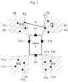
- FIG. 1 shows the entire configuration of an embodiment of a camera calibration system in accordance with the present invention.
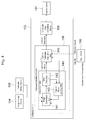
- a camera calibration system 100 shown in Fig. 1 mainly includes an imaging device 101 having four cameras 111 to 114; a camera interface 102; an image storage device (RAM) 104; a parameter storage device (ROM) 105; an input device 106; an arithmetic unit 103 having a camera calibration device 108 and a composite image generation device 109; and a display device 107.
- the cameras 111 to 114 of the imaging device 101 are arranged on the front, rear, right, and left parts of a vehicle 1, respectively, for example, so that images of areas around the vehicle 1, including a calibration target R, are captured by the four cameras 111 to 114.
- the calibration target R includes information that is necessary for calibration of the cameras, such as calibration patterns (see Fig. 3 ) that serve as calibration indices (described below), for example.
- the cameras 111 to 114 capture images of the calibration target R, and transmit the captured images to the arithmetic unit 103 via the camera interface 102.
- the dotted line in Fig. 2 represents an imaging area of each of the cameras 111 to 114.
- adjacent cameras have an overlapped portion, that is, a common area (hereinafter referred to as a "common imaging area") RK1 to RK4 imaged by the two cameras.
- the arithmetic unit 103 calculates camera parameters for calibrating images captured by the cameras 111 to 114, using the camera calibration device 108.
- the camera parameters are transmitted to the composite image generation device 109.
- images captured by the cameras 111 to 114 are transmitted to the arithmetic unit 103 via the camera interface 102, and are subjected to viewpoint conversion and synthesis by the composite image generation device 109 of the arithmetic unit 103 using the camera parameters, and then, the resulting image is transmitted to the display device 107, and is presented as an image seen from right above the vehicle 1 (i.e., bird's-eye image) to a user or the like via the display device 107.
- this embodiment is based on the assumption that a bird's-eye image of an area around the vehicle 1 is generated through viewpoint conversion and synthesis of images obtained from the cameras 111 to 114.
- a camera that can capture an image at wide angles such as a fish-eye camera, is desirably adopted as each of the cameras 111 to 114.
- the camera interface 102 properly samples image signals transmitted from the cameras 111 to 114, and transmits the image signals to the arithmetic unit 103 as described above.
- the image storage device (RAM) 104 stores images captured by the cameras 111 to 114 and results of a variety of computations performed by the arithmetic unit 103.
- the parameter storage device (ROM) 105 has written thereto, for example, information, which is necessary for calibration of camera images, on camera parameters (i.e., initial camera parameter values), such as design values related to the installation positions and the postures (i.e., installation angles) of the cameras 111 to 114 (which are called “external parameters”), and design values related to the focal lengths, the pixel sizes, the centers of the optical axes, and distortion functions of the cameras 111 to 114 (which are called “internal parameters").
- camera parameters i.e., initial camera parameter values
- design values related to the installation positions and the postures (i.e., installation angles) of the cameras 111 to 114 which are called "external parameters”
- design values related to the focal lengths, the pixel sizes, the centers of the optical axes, and distortion functions of the cameras 111 to 114 which are called “internal parameters”
- the input device 106 receives input information, such as information that is necessary for calibration of the cameras, based on a user operation or the like, and transmits the input information to the arithmetic unit 103.
- the arithmetic unit 103 operates in conjunction with the camera interface 102, the image storage device (RAM) 104, the parameter storage device (ROM) 105, the input device 106, the display device 107, and the like to perform a variety of computations including the aforementioned computations performed in calibration of camera images. Specifically, the arithmetic unit 103 stores image signals transmitted from the camera interface 102 into the image storage device 104, and reads the initial camera parameter values stored in the parameter storage device 105 and the images stored in the image storage device 104 to perform viewpoint conversion and synthesis on the images (i.e., the composite image generation device 109), or performs a process of displaying a viewpoint-converted composite image on the display device 107, for example.
- the arithmetic unit 103 stores image signals transmitted from the camera interface 102 into the image storage device 104, and reads the initial camera parameter values stored in the parameter storage device 105 and the images stored in the image storage device 104 to perform viewpoint conversion and synthesis on the images (i.e
- the arithmetic unit 103 performs calibration computation for calculating the installation position and the installation posture of each camera so that a bird's-eye image generated through viewpoint conversion and synthesis becomes an image seen from right above the vehicle 1 (i.e., the camera calibration device 108), or performs a process of using input information that is received on the input device 106 from a user or the like for the calibration computation. It should be noted that the computation process for calibrating camera images is described below.
- the display device 107 displays images obtained from the cameras 111 to 114 based on an instruction transmitted from the arithmetic unit 103. For example, the display device 107 displays and presents the images to a user or the like without converting only the image of the camera 112 that faces rearward in accordance with an instruction transmitted from the arithmetic unit 103, or displays a bird's-eye image generated through viewpoint conversion and synthesis of the images obtained from the cameras 111 to 114.
- a computation process for calibrating camera images performed by the camera calibration device 108 of the arithmetic unit 103 shown in Fig. 1 i.e., an embodiment of the camera calibration device in accordance with the present invention
- a process of computing the camera parameters of each of the cameras 111 to 114 performed by the camera calibration device 108 will be described in detail with reference to Figs. 3 and 4 .
- the vehicle 1 is placed in a calibration target R that is used for a computation process for calibrating camera images performed by the camera calibration device 108, while calibration patterns P1 to P16, which are calibration indices, are arranged at least in common imaging areas RK1 to RK4 of adjacent cameras around the vehicle 1.
- Each of the calibration patterns P1 to P16 is formed of a plate that has a plane and is in the shape of a disc or a polygon such as a square, for example, and has about a size that can be, when imaged by each of the cameras 111 to 114, viewed on the image.
- each of the calibration patterns P1 to P16 can be adequately selected as long as, when each calibration pattern is formed of a disc-shaped plate, a landmark portion for uniquely identifying the calibration pattern is provided in the center of the plate, or, when each calibration pattern is formed of a square plate, a landmark portion for uniquely identifying the calibration pattern is provided in a corner of the plate.
- calibration patterns in each common imaging area may have either the same shape or different shapes.
- each calibration pattern P1 to P4 are arranged in a common imaging area RK1 of the cameras 111 and 114
- four calibration patterns P5 to P8 are arranged in a common imaging area RK2 of the cameras 111 and 113
- four calibration patterns P9 to P12 are arranged in a common imaging area RK3 of the cameras 113 and 112
- four calibration patterns P13 to P16 are arranged in a common imaging area RK4 of the cameras 112 and 114.
- Such calibration patterns can be arranged at any positions in each common imaging area. However, the gap between adjacent calibration patterns is desirably large. In addition, the number of calibration patterns that are arranged in each common imaging area can be changed as appropriate in accordance with the calibration accuracy, for example.
- calibration patterns are auxiliary calibration indices that are used in calibration of camera images. That is, calibration of camera images is possible as long as texture patterns are drawn on the background plane, in principle, even if there are no points like calibration patterns.
- At least two (e.g., P1 and P5 in Fig. 3 ) of the 16 calibration patterns shown in this embodiment are necessary to uniquely define the heights of the cameras.
- the gap between the two calibration patterns is measured by an operator or the like and is input to a camera parameter calculation unit 145 via the input device 106 in advance.
- the gap between two calibration patterns input by an operator or the like is used to determine the distance corresponding to one pixel.
- Calibration is performed for a plurality of cameras. After a bird's-eye viewpoint image is generated with the distance corresponding to one pixel unknown, the distance between two calibration patterns input by an operator or the like is used to calculate the distance or scale corresponding to the size of one pixel, so that a final bird's-eye image is generated.
- the aforementioned calibration patterns may be arranged at any positions as long as the calibration patterns can be imaged by any of the four cameras.
- the calibration patterns are desirably arranged in a common imaging area. This is because in this embodiment, calibration is performed through position adjustment of two captured images of each common imaging area, and thus, if calibration patterns are arranged in each common imaging area, the calibration patterns can be used as landmarks in performing position adjustment of two images. That is, position adjustment of images becomes easier with a larger number of landmarks for position adjustment of images.
- the number of calibration patterns that are arranged in each common imaging area is desirably large.
- an object i.e., feature object
- points that can be used for calibration i.e., feature points
- object may be not only a three-dimensional object but also a plane such as a pattern or a texture, for example, sandy soil or asphalt.
- calibration is performed using feature points of an object that is present in a common imaging area, it is necessary to determine if the object is contained in the target common imaging area.
- a standard deviation of luminance values in the common imaging area for example.
- the calculated value of the standard deviation is greater than or equal to a predetermined threshold, it can be determined that an object with feature points that can be used for calibration is present, while if the value of the calculated standard deviation is less than the threshold, it can be determined that such an object is not present. If it is determined that such an object is not present, calibration patterns are necessary. Thus, information to the effect that calibration patterns should be arranged is sent to an operator via the display device 107.
- the aforementioned computation process for calibrating camera images performed by the camera calibration device 108 using the calibration target R is performed using a projection matrix related to the ground (i.e., plane).
- a projection matrix related to the ground i.e., plane
- two camera images corresponding to a given common imaging area contain the same ground (i.e., plane).
- a target to be imaged is a plane
- one of the two images can be converted into the same image as the other image (i.e., an image seen from the viewpoint of one camera can be converted into an image seen from the viewpoint of the other camera) through geometric conversion using a projection matrix.
- the "projection matrix” herein is a matrix that represents the projection relationship between planes that are contained in two camera images corresponding to a given common imaging area, and the projection matrix includes relative external parameters of the two cameras and a normal vector to the plane in each image.
- singular value decomposition for the projection matrix can extract the relative external parameters of the two cameras and the normal vector to the plane. It should be noted that as singular value decomposition for a projection matrix is a known technique, the detailed description thereof will be omitted.
- each camera image is converted into a bird's-eye image seen from right above the vehicle 1, while if the relative external parameters of the two cameras are known, it becomes possible to combine bird's-eye images of the two cameras corresponding to a common imaging area without deviation, and thus form a composite image.
- a projection matrix that is used for a computation process for calibrating camera images is calculated based on an iterative method, for example.
- the iterative method is a method for repeating the procedures of determining the current error and updating a projection matrix such that the error becomes smaller. Examples include a method based on differentiation, such as a method of steepest descent, a Gauss-Newton method, or a Levenberg-Marquardt Method, and a method without differentiation, such as a particle filter or a genetic algorithm.
- the method of steepest descent is a method for repeating the procedures of differentiating an error function to determine the decreasing direction of the error function, and updating the parameter slightly in the decreasing direction, until a decrease of the error stops.
- the camera calibration device 108 includes, as shown in Fig. 4 , a calibration unit 144 having an image conversion unit 141, an error evaluation unit 142, and a projection matrix updating unit 143; and the camera parameter calculation unit 145 to estimate camera parameters for generating a bird's-eye image without deviation.
- the calibration unit 144 is adapted to calculate a projection matrix for two cameras corresponding to each common imaging area, and performs an image conversion process with the image conversion unit 141, an error evaluation process with the error evaluation unit 142, and an updating process with the projection matrix updating unit 143 on each of two images corresponding to each of the four common imaging areas RK1 to RK4.
- the calibration unit 144 performs an image conversion process with the image conversion unit 141, an error evaluation process with the error evaluation unit 142, and an updating process with the projection matrix updating unit 143 on each of two images of the cameras 111 and 114 corresponding to the common imaging area RK1, two images of the cameras 111 and 113 corresponding to the common imaging area RK2, two images of the cameras 112 and 113 corresponding to the common imaging area RK3, and two images of the cameras 112 and 114 corresponding to the common imaging area RK4.
- the image conversion unit 141 of the calibration unit 144 receives images of the cameras 111 to 114 from the image storage unit 104, and converts the viewpoints of two images corresponding to each common imaging area using a projection matrix obtained by the projection matrix updating unit 143, and then transmits the viewpoint-converted images to the error evaluation unit 142.
- the projection matrix used for the viewpoint conversion herein is a matrix for, when processing images of the two cameras 111 and 114 corresponding to the common imaging area RK1, for example, performing conversion for matching an image of the ground (i.e., plane) including the calibration patterns P1 to P4 captured by the camera 114 with an image of the ground including the calibration patterns P1 to P4 captured by the camera 111. It should be noted that the two images do not become perfectly matching images even when the projection matrix is used as the two images inevitably contain errors. However, the image of the camera 114 becomes closer to the image of the camera 111.
- a projection matrix cannot be obtained from the projection matrix updating unit 143. Therefore, image conversion is performed after calculating a projection matrix (i.e., initial projection matrix) for performing conversion for matching images of the ground (i.e., plane), which have been captured by two cameras corresponding to each common shooing area, with each other based on the design values (initial parameters) related to the postures of the cameras 111 to 114 stored in the parameter storage unit 105 in advance. Then, in the second and subsequent image conversion processes for calibration, the viewpoints of images of the two cameras corresponding to each common imaging area are converted using the projection matrix obtained by the projection matrix updating unit 143.
- a projection matrix i.e., initial projection matrix
- each common imaging area is arranged as the feature points of a calibration target.
- four calibration patterns which serve as calibration indices, are arranged in each common imaging area as described above, it is possible to, by solving simultaneous equations created for the four calibration patterns in images captured by two cameras corresponding to each common imaging area, uniquely determine a projection matrix for converting the coordinate positions of the four calibration patterns in one camera image into the coordinate positions of the four calibration patterns in the other camera image. That is, when four or more calibration patterns are arranged in each common imaging area, the image conversion unit 141 can perform image conversion using a projection matrix, which has been obtained from simultaneous equations created for the four or more calibration patterns, as an initial projection matrix used in the initial image conversion process of the image conversion unit 141.
- the error evaluation unit 142 evaluates an error between two camera images corresponding to each common imaging area, which have been subjected to image conversion by the image conversion unit 141, and transmits the error between the two camera images to the projection matrix updating unit 143. For example, when images of the two cameras 111 and 114 corresponding to the common imaging area RK1 are processed, the image of the camera 114 is converted such that it matches the image of the camera 111 by the image conversion unit 141. However, in the initial image conversion process by the image conversion unit 141, for example, the image is converted based on the design values stored in the parameter storage unit 105 in advance.
- the image of the camera 114 does not perfectly match the image of the camera 111 even if image conversion based on the design values is performed based on the actual installation errors of the cameras and the like. Thus, an error inevitably occurs between the two images.
- the error evaluation unit 142 evaluates the amount of such error between the two camera images. It should be noted that the error evaluation unit 142 transmits a projection matrix output from the image conversion unit 141 to the camera parameter calculation unit 145.
- Examples of the amount of an error between two camera images that is evaluated by the error evaluation unit 142 include the sum of squares of the distance between corresponding calibration patterns, the sum of squares of the luminance difference between corresponding pixels, and the total sum of the sum of squares of the distance and the sum of squares of the luminance difference.
- the difference between the feature quantities of the object in the corresponding pixels of the common imaging area is determined to be the amount of an error.
- the feature quantity of an object is desirably the one that is not susceptible to the influence of the difference in sensitivity or the difference in the amount of incident light between cameras.
- a feature quantity in the edge direction is used.
- a feature quantity in the edge direction represents the direction in which the luminance locally increases in each pixel.
- a feature object can be determined based on a distribution of feature quantities in the edge direction in an image or on statistics (e.g., mean value) of the feature quantities in the edge direction of each object.
- a projection matrix for two images can be determined by using the matching degree of such feature quantities as an error function and performing optimization so that an error becomes minimum.
- the projection matrix updating unit 143 based on the error obtained by the error evaluation unit 142 and the pre-updated projection matrix transmitted from the calibration unit 144 to the camera parameter calculation unit 145, updates the projection matrix using an iterative method so that the error becomes smaller, and transmits the updated projection matrix to the image conversion unit 141.
- the projection matrix updating unit 143 updates the projection matrix by determining partial differentiation of an error function of the current camera parameters, and slightly updating the camera parameters in the opposite direction to the direction of a vector represented by the partial differentiation of the error function.
- the calibration unit 144 calculates a projection matrix for performing conversion so that two camera images corresponding to each common imaging area become the same (i.e., an error becomes zero) by repeatedly performing an image conversion process with the image conversion unit 141, an error evaluation process with the error evaluation unit 142, and an updating process with the projection matrix updating unit 143 on each of the two camera images corresponding to each common imaging area, and transmits the calculation results to the camera parameter calculation unit 145.
- the camera parameter calculation unit 145 decomposes the projection matrixes corresponding to the four cameras 111 to 114 obtained by the calibration unit 144, using singular value decomposition or the like, and extracts a normal vector to the ground (i.e., plane) and relative external parameters of the cameras, and then transmits camera parameters calculated from the relative external parameters of the cameras (in particular, external parameters related to the postures of the cameras with respect to the plane (i.e., ground)) to the composite image generation device 109.
- the relative external parameters of the cameras are obtained in the forms of a relative external parameter of the camera 114 with respect to the camera 111, a relative external parameter of the camera 113 with respect to the camera 111, a relative external parameter of the camera 112 with respect to the camera 114, and a relative external parameter of the camera 112 with respect to the camera 113, such relative external parameters are re-calculated to become relative external parameters with respect to a camera, which serves as a reference (i.e., reference camera), selected from among the cameras 111 to 114, and also, the posture of the reference camera with respect to the plane (i.e., ground) is calculated from the normal vector to the plane (i.e., ground).
- a reference i.e., reference camera
- the camera parameter calculation unit 145 may also estimate internal parameters related to the focal lengths, the pixel sizes, the centers of the optical axes, and distortion functions of the respective cameras, for example, as needed.
- the camera parameters output from the camera parameter calculation unit 145 are used to create a mapping table for generating a bird's-eye image with the composite image generation device 109.
- the "mapping table” herein is a table containing the correspondence between each pixel in a composite bird's-eye image and a pixel in each of the images of the cameras 111 to 114. Performing mapping of luminance values based on such correspondence can obtain a final composite bird's-eye image.
- images captured with cameras are calibrated with respect to each other using a projection matrix related to the ground (i.e., plane).
- a projection matrix related to the ground i.e., plane.
- a projection matrix is determined for performing viewpoint conversion into a bird's-eye viewpoint such that the captured images containing calibration patterns, which are calibration indices, match between cameras corresponding to a common imaging area.
- a projection matrix that satisfies a condition that two camera images corresponding to a common imaging area should match is determined.
- texture information is insufficient, it may be impossible to perform sufficient position adjustment only with the condition that two camera images corresponding to a common imaging area should match.
- a calibration target in particular, feature points in a common imaging area that are contained in the calibration target are extracted, and the coordinates of the extracted feature points are input to the image conversion unit 141 of the calibration unit 144, and then, a projection matrix for performing viewpoint conversion is determined by adding a condition that the coordinates of the feature points should match, so that the calculation accuracy of the projection matrix can be improved.
- the coordinates of the feature points may be extracted through image recognition, or alternatively, an image may be presented to a user or the like via the display device 107 or the like so that the user or the like may specify the coordinates of the feature points on the image via the input device 106 such as a mouse.
- Information obtained by the camera calibration device 108 in this embodiment is the camera posture of each of the cameras with respect to the plane (i.e., ground), and the relationship of the relative positions and postures of the cameras. Therefore, it is, in principle, impossible to determine the relative rotation amount of the vehicle 1 with respect to the ground (i.e., the rotation amount of the vehicle 1 in the yaw direction). However, when an error of the initial installation position(s) of a camera(s) is small, the relative rotation amount of the vehicle 1 with respect to the ground can be estimated from the direction of the axle of the vehicle 1 by using information on the installation position of the cameras.
- the relative rotation amount of the vehicle 1 with respect to the ground can be estimated by arranging landmarks for recognizing the relationship between the ground and the vehicle 1 around the vehicle 1 (i.e., arranging bars in parallel with the vehicle 1), and providing a means for correcting the relative rotation amount of the vehicle 1 with respect to the ground.
- a rotation amount i.e., information input shown by the chain line in Fig. 4
- the input device 106 may input a rotation amount (i.e., information input shown by the chain line in Fig. 4 ) through fine adjustment via the input device 106 so that landmarks for recognizing the relationship between the ground and the vehicle 1 have predetermined looks.
- the input results are promptly reflected by the image.
- the user or the like can adjust the relative rotation amount of the vehicle 1 with respect to the ground while checking the image.
- the flow of the calibration computation process includes an image acquisition process S501, an initial projection matrix generation process S502, an image conversion process S503, an error evaluation process S504, a projection matrix updating process S505, a convergence determination process S508, and a scale correction process S509.
- the projection matrix updating process S505 includes an update amount calculation process 506 and a projection matrix calculation process 507.
- the image acquisition process S501, the image conversion process S503, the error evaluation process S504, the convergence determination process S508, and the projection matrix updating process S505 are sequentially performed. Thereafter, the image conversion process S503, the error evaluation process S504, the convergence determination process S508, and the projection matrix updating process S505 are repeatedly performed. When an error evaluation value is evaluated and is determined to have converged in the convergence determination process S508, the process stops.
- the image acquisition process S501 is performed to read an image captured by each camera from the image storage device 104.
- the image conversion process S503 is performed using a projection matrix.
- a projection matrix in the initial calibration is calculated in the initial projection matrix generation process S502, and in the initial projection matrix generation process S502, initial camera parameters including the camera postures and positions are received from the parameter storage unit 105, so that a projection matrix corresponding to the initial camera parameters is calculated.
- the obtained initial projection matrix is used in the initial process of the image conversion process S503, and in the following process of the image conversion process S503, a projection matrix output in the projection matrix updating process S505 is used.
- the error evaluation process S504 is performed by the error evaluation unit 142 shown in Fig. 4 .
- outputs of the image conversion process S503 are received so as to calculate the amount of an error that represents how much one of the two camera images corresponding to each common imaging area portion deviates from the other camera image corresponding to the common imaging area portion, and output the calculation results.
- the amount of an error output in the error evaluation process S504 is compared with a predetermined determination threshold to execute the convergence determination process S508.
- the convergence determination process S508 if the amount of an error output in the error evaluation process S504 has converged is determined. If the error is not determined to have converged, the projection matrix updating process S505 is performed by the projection matrix updating unit 143 shown in Fig. 4 .
- the projection matrix updating process S505 includes the update amount calculation process 506 and the projection matrix calculation process 507.
- the update amount calculation process 506 the amount of update to be applied to a camera parameter, such as a camera posture or position, is calculated.
- the “amount of update” herein is the amount of fine modification to be applied to a camera parameter, such as a camera posture or position, so that the amount of an error, which represents how much one of the two images corresponding to each common imaging area portion matches the other image corresponding to the common imaging area portion, becomes smaller.
- the amount of update can be calculated by determining partial differentiation of an error function of the current camera parameters.
- the value of the finely modified camera parameter is output.
- the output value in the update amount calculation process 506 is received so that a projection matrix corresponding to the camera parameter is calculated and output.
- the image conversion process S503, the error evaluation process S504, and the projection matrix updating process S505 are repeatedly performed until the output value in the error evaluation process S504 is converged.
- the amount of an error output in the error evaluation process S504 is evaluated in each execution. When the amount of an error is determined to have become extremely small, it is determined that the error has converged and the process is thus terminated.
- the image conversion process S503, the error evaluation process S504, and the projection matrix updating process S505 are repeatedly performed, it is possible to match one of the two images corresponding to each common imaging area portion with the other image corresponding to the common imaging area portion.
- the scale correction process S509 is performed to correct the size of the pixel.
- distance information about the gap between calibration patterns which has been measured by an operator or the like and input via the input device 106, is used to correct the camera parameters, so that a final bird's-eye image is generated.
- how many pixels the gap between calibration patterns should look in the bird's-eye image is calculated, and the camera parameters are corrected so that the gap between the calibration patterns in the bird's-eye image becomes the actually calculated pixel gap. Calibration of the cameras can be realized through the aforementioned process.
- the present invention is not limited to the aforementioned embodiments, and includes a variety of variations.
- the present invention need not include all of the configurations described in the embodiments. It is possible to replace a part of a configuration of an embodiment with a configuration of another embodiment.
- control lines and information lines represent those that are considered to be necessary for the description, and do not necessarily represent all control lines and information lines that are necessary for a product. Thus, in practice, almost all configurations may be considered to be mutually connected.
Applications Claiming Priority (2)
| Application Number | Priority Date | Filing Date | Title |
|---|---|---|---|
| JP2013180212 | 2013-08-30 | ||
| PCT/JP2014/072119 WO2015029934A1 (ja) | 2013-08-30 | 2014-08-25 | カメラ校正装置、カメラ校正システム、及びカメラ校正方法 |
Publications (2)
| Publication Number | Publication Date |
|---|---|
| EP3041228A1 true EP3041228A1 (de) | 2016-07-06 |
| EP3041228A4 EP3041228A4 (de) | 2017-06-28 |
Family
ID=52586492
Family Applications (1)
| Application Number | Title | Priority Date | Filing Date |
|---|---|---|---|
| EP14840004.7A Withdrawn EP3041228A4 (de) | 2013-08-30 | 2014-08-25 | Kamerakalibrierungsvorrichtung, kamerakalibrierungssystem und kamerakalibrierungsverfahren |
Country Status (5)
| Country | Link |
|---|---|
| US (1) | US20160176343A1 (de) |
| EP (1) | EP3041228A4 (de) |
| JP (1) | JP6154905B2 (de) |
| CN (1) | CN105474634A (de) |
| WO (1) | WO2015029934A1 (de) |
Cited By (5)
| Publication number | Priority date | Publication date | Assignee | Title |
|---|---|---|---|---|
| WO2017080753A1 (en) * | 2015-11-12 | 2017-05-18 | Robert Bosch Gmbh | Vehicle camera system with multiple-camera alignment |
| EP3418122A4 (de) * | 2016-06-15 | 2019-03-27 | JVC KENWOOD Corporation | Positionsänderungsbestimmungsvorrichtung, überkopfbilderzeugungsvorrichtung, überkopfbilderzeugungssystem, positionsänderungsbestimmungsverfahren und programm |
| CN109584307A (zh) * | 2017-09-28 | 2019-04-05 | 百度(美国)有限责任公司 | 改进摄像机固有参数校准的系统和方法 |
| CN110881123A (zh) * | 2018-09-06 | 2020-03-13 | 爱信精机株式会社 | 照相机校准装置 |
| US10593016B2 (en) | 2015-06-19 | 2020-03-17 | Sony Corporation | Image processing unit, image processing method, and projection system |
Families Citing this family (37)
| Publication number | Priority date | Publication date | Assignee | Title |
|---|---|---|---|---|
| US9684837B2 (en) * | 2014-02-24 | 2017-06-20 | Nissan Motor Co., Ltd. | Self-location calculating device and self-location calculating method |
| WO2016077057A2 (en) * | 2014-10-24 | 2016-05-19 | Bounce Imaging, Inc. | Imaging systems and methods |
| WO2016068997A1 (en) * | 2014-10-31 | 2016-05-06 | Hewlett-Packard Development Company, L.P. | Cross-calibration of imagers |
| JP6540155B2 (ja) * | 2015-03-27 | 2019-07-10 | 沖電気工業株式会社 | 画像処理装置、方法及びプログラム、並びに画像処理システム |
| DE102016206493A1 (de) * | 2015-06-23 | 2016-12-29 | Robert Bosch Gmbh | Verfahren und Kamerasystem zur Entfernungsbestimmung von Objekten zu einem Fahrzeug |
| KR101699414B1 (ko) * | 2015-10-15 | 2017-01-24 | 서울시립대학교 산학협력단 | 이온트랩 기반의 양자역학적 인공 시각 시스템 및 연산 방법 |
| TWI555378B (zh) * | 2015-10-28 | 2016-10-21 | 輿圖行動股份有限公司 | 一種全景魚眼相機影像校正、合成與景深重建方法與其系統 |
| US10453217B2 (en) * | 2016-03-24 | 2019-10-22 | Magna Electronics Inc. | Targetless vehicle camera calibration system |
| KR102597435B1 (ko) * | 2016-04-20 | 2023-11-03 | 엘지이노텍 주식회사 | 영상 취득 장치 및 그 방법 |
| JP6723820B2 (ja) * | 2016-05-18 | 2020-07-15 | 株式会社デンソーテン | 画像生成装置、画像表示システムおよび画像表示方法 |
| US10165256B2 (en) * | 2016-09-14 | 2018-12-25 | Amazon Technologies, Inc. | Aerial vehicle optical sensor configuration |
| CN107945234A (zh) * | 2016-10-12 | 2018-04-20 | 杭州海康威视数字技术股份有限公司 | 一种立体摄像机外部参数的确定方法及装置 |
| WO2018087856A1 (ja) * | 2016-11-10 | 2018-05-17 | 三菱電機株式会社 | 映像合成装置及び映像合成方法 |
| US10504241B2 (en) | 2016-12-19 | 2019-12-10 | Magna Electronics Inc. | Vehicle camera calibration system |
| JP6636963B2 (ja) * | 2017-01-13 | 2020-01-29 | 株式会社東芝 | 画像処理装置及び画像処理方法 |
| US10466027B2 (en) | 2017-06-21 | 2019-11-05 | Fujitsu Ten Corp. Of America | System and method for marker placement |
| JP7054803B2 (ja) | 2017-07-21 | 2022-04-15 | パナソニックIpマネジメント株式会社 | カメラパラメタセット算出装置、カメラパラメタセット算出方法及びプログラム |
| JP6962372B2 (ja) | 2017-08-25 | 2021-11-05 | 株式会社ソシオネクスト | 補正装置、補正プログラム及び記録媒体 |
| US11012683B1 (en) | 2017-09-28 | 2021-05-18 | Alarm.Com Incorporated | Dynamic calibration of surveillance devices |
| US10636173B1 (en) | 2017-09-28 | 2020-04-28 | Alarm.Com Incorporated | Dynamic calibration of surveillance devices |
| US10482626B2 (en) * | 2018-01-08 | 2019-11-19 | Mediatek Inc. | Around view monitoring systems for vehicle and calibration methods for calibrating image capture devices of an around view monitoring system using the same |
| US20210033712A1 (en) * | 2018-02-09 | 2021-02-04 | Sony Corporation | Calibration apparatus, calibration method, and program |
| WO2019176930A1 (ja) * | 2018-03-15 | 2019-09-19 | 株式会社 村上開明堂 | 合成映像作成装置および合成映像作成方法並びに合成映像作成プログラム |
| KR102477480B1 (ko) * | 2018-03-20 | 2022-12-14 | 주식회사 에이치엘클레무브 | 어라운드뷰 카메라의 캘리브레이션 장치 및 그 방법 |
| JP2019180016A (ja) * | 2018-03-30 | 2019-10-17 | パナソニックIpマネジメント株式会社 | 画像合成装置、画像合成方法及びプログラム |
| US10904434B2 (en) | 2018-09-28 | 2021-01-26 | Bounce Imaging, Inc. | Panoramic camera and image processing systems and methods |
| KR102559203B1 (ko) | 2018-10-01 | 2023-07-25 | 삼성전자주식회사 | 포즈 정보를 출력하는 방법 및 장치 |
| KR102525030B1 (ko) * | 2018-12-11 | 2023-04-24 | 삼성전자주식회사 | 포인트 클라우드를 생성하는 방법 및 장치 |
| CN109636874B (zh) * | 2018-12-17 | 2023-05-26 | 浙江科澜信息技术有限公司 | 一种三维模型透视投影方法、系统及相关装置 |
| CN109903341B (zh) * | 2019-01-25 | 2023-09-08 | 东南大学 | 一种车载摄像机外参动态自标定方法 |
| WO2020170288A1 (ja) * | 2019-02-18 | 2020-08-27 | 三菱電機株式会社 | 画像処理装置、画像処理方法、及び画像処理プログラム |
| KR20200126540A (ko) * | 2019-04-30 | 2020-11-09 | 주식회사 만도 | 카메라 보정 시스템 및 그 방법 |
| KR102274026B1 (ko) * | 2019-05-22 | 2021-07-09 | (주)베이다스 | 차량용 카메라 캘리브레이션 장치 및 그 방법 |
| KR102297683B1 (ko) * | 2019-07-01 | 2021-09-07 | (주)베이다스 | 복수의 카메라들을 캘리브레이션하는 방법 및 장치 |
| KR102277828B1 (ko) * | 2019-08-13 | 2021-07-16 | (주)베이다스 | 복수의 카메라들을 캘리브레이션하는 방법 및 장치 |
| JP2020174363A (ja) * | 2020-06-23 | 2020-10-22 | 株式会社リコー | 撮影システム、方法およびプログラム |
| WO2022250238A1 (ko) * | 2021-05-25 | 2022-12-01 | (주) 이즈커뮤니케이션즈 | 컴퓨터에의 정보 입력 시스템 및 이 정보 입력 시스템을 이용한 입력 정보의 좌표 산출 방법 |
Family Cites Families (16)
| Publication number | Priority date | Publication date | Assignee | Title |
|---|---|---|---|---|
| JP2008187566A (ja) | 2007-01-31 | 2008-08-14 | Sanyo Electric Co Ltd | カメラ校正装置及び方法並びに車両 |
| JP2008187564A (ja) * | 2007-01-31 | 2008-08-14 | Sanyo Electric Co Ltd | カメラ校正装置及び方法並びに車両 |
| DE102009050368A1 (de) * | 2008-10-24 | 2010-05-27 | Magna Electronics Europe Gmbh & Co.Kg | Verfahren zum automatischen Kalibrieren einer virtuellen Kamera |
| JP5523730B2 (ja) * | 2009-04-07 | 2014-06-18 | アルパイン株式会社 | 車載周辺画像表示装置 |
| JP5299231B2 (ja) * | 2009-11-17 | 2013-09-25 | 富士通株式会社 | キャリブレーション装置 |
| JP5491235B2 (ja) * | 2010-03-02 | 2014-05-14 | 東芝アルパイン・オートモティブテクノロジー株式会社 | カメラキャリブレーション装置 |
| JP5552892B2 (ja) * | 2010-05-13 | 2014-07-16 | 富士通株式会社 | 画像処理装置および画像処理プログラム |
| KR101113679B1 (ko) * | 2010-05-24 | 2012-02-14 | 기아자동차주식회사 | 카메라 시스템의 영상 보정 방법 |
| JP5444139B2 (ja) * | 2010-06-29 | 2014-03-19 | クラリオン株式会社 | 画像のキャリブレーション方法および装置 |
| WO2012143036A1 (en) * | 2011-04-18 | 2012-10-26 | Connaught Electronics Limited | Online vehicle camera calibration based on continuity of features |
| EP2530647A1 (de) * | 2011-06-01 | 2012-12-05 | Harman Becker Automotive Systems GmbH | Verfahren zur Kalibrierung eines Fahrzeugsichtsystems und Fahrzeugsichtsystem |
| JP5804892B2 (ja) * | 2011-10-25 | 2015-11-04 | セコム株式会社 | カメラ姿勢算出装置 |
| US9491451B2 (en) * | 2011-11-15 | 2016-11-08 | Magna Electronics Inc. | Calibration system and method for vehicular surround vision system |
| JP5898475B2 (ja) * | 2011-11-28 | 2016-04-06 | クラリオン株式会社 | 車載カメラシステム及びその較正方法、及びその較正プログラム |
| CN103035005B (zh) * | 2012-12-13 | 2015-08-05 | 广州致远电子股份有限公司 | 一种全景泊车的标定方法,及装置,一种自动标定方法 |
| CN103196678A (zh) * | 2013-03-26 | 2013-07-10 | 北京嘉悦和汽车科技有限公司 | 基于dsp的四轮定位仪输入图像实时校正装置和方法 |
-
2014
- 2014-08-25 JP JP2015534193A patent/JP6154905B2/ja not_active Expired - Fee Related
- 2014-08-25 EP EP14840004.7A patent/EP3041228A4/de not_active Withdrawn
- 2014-08-25 CN CN201480045455.3A patent/CN105474634A/zh active Pending
- 2014-08-25 WO PCT/JP2014/072119 patent/WO2015029934A1/ja active Application Filing
- 2014-08-25 US US14/907,852 patent/US20160176343A1/en not_active Abandoned
Non-Patent Citations (1)
| Title |
|---|
| See references of WO2015029934A1 * |
Cited By (6)
| Publication number | Priority date | Publication date | Assignee | Title |
|---|---|---|---|---|
| US10593016B2 (en) | 2015-06-19 | 2020-03-17 | Sony Corporation | Image processing unit, image processing method, and projection system |
| WO2017080753A1 (en) * | 2015-11-12 | 2017-05-18 | Robert Bosch Gmbh | Vehicle camera system with multiple-camera alignment |
| EP3418122A4 (de) * | 2016-06-15 | 2019-03-27 | JVC KENWOOD Corporation | Positionsänderungsbestimmungsvorrichtung, überkopfbilderzeugungsvorrichtung, überkopfbilderzeugungssystem, positionsänderungsbestimmungsverfahren und programm |
| CN109584307A (zh) * | 2017-09-28 | 2019-04-05 | 百度(美国)有限责任公司 | 改进摄像机固有参数校准的系统和方法 |
| CN109584307B (zh) * | 2017-09-28 | 2022-12-30 | 百度(美国)有限责任公司 | 改进摄像机固有参数校准的系统和方法 |
| CN110881123A (zh) * | 2018-09-06 | 2020-03-13 | 爱信精机株式会社 | 照相机校准装置 |
Also Published As
| Publication number | Publication date |
|---|---|
| JPWO2015029934A1 (ja) | 2017-03-02 |
| CN105474634A (zh) | 2016-04-06 |
| JP6154905B2 (ja) | 2017-06-28 |
| EP3041228A4 (de) | 2017-06-28 |
| WO2015029934A1 (ja) | 2015-03-05 |
| US20160176343A1 (en) | 2016-06-23 |
Similar Documents
| Publication | Publication Date | Title |
|---|---|---|
| EP3041228A1 (de) | Kamerakalibrierungsvorrichtung, kamerakalibrierungssystem und kamerakalibrierungsverfahren | |
| WO2017135081A1 (ja) | 車載カメラ用校正システム | |
| CN112907676B (zh) | 传感器的标定方法、装置、系统、车辆、设备及存储介质 | |
| JP5322789B2 (ja) | モデル生成装置、モデル生成方法、モデル生成プログラム、点群画像生成方法および点群画像生成プログラム | |
| CN103278138B (zh) | 一种复杂结构薄部件三维位置及姿态的测量方法 | |
| JP5134784B2 (ja) | 空中写真測量方法 | |
| WO2015198930A1 (ja) | 測距装置および補正パラメータを用いた測距補正装置 | |
| JP2014064224A (ja) | カメラのキャリブレーション方法及び装置 | |
| US10687052B2 (en) | Camera parameter calculation method, recording medium, camera parameter calculation apparatus, and camera parameter calculation system | |
| US8577139B2 (en) | Method of orthoimage color correction using multiple aerial images | |
| CN104537707A (zh) | 像方型立体视觉在线移动实时测量系统 | |
| EP3783385A1 (de) | Kombinierte punktwolkenerzeugung unter verwendung eines stationären laserscanners und eines mobilen scanners | |
| US10771776B2 (en) | Apparatus and method for generating a camera model for an imaging system | |
| JP6544257B2 (ja) | 情報処理システム、情報処理方法及び情報処理プログラム | |
| KR20210049581A (ko) | 이동체의 전방향에 대한 거리 취득 장치 및 방법 | |
| CN112967344B (zh) | 相机外参标定的方法、设备、存储介质及程序产品 | |
| CN109285195B (zh) | 基于大尺寸靶标的单目投影系统逐像素畸变校正方法及其应用 | |
| US10083509B2 (en) | Image calibration | |
| CN111105467B (zh) | 一种图像标定方法、装置及电子设备 | |
| CN114283201A (zh) | 相机标定方法、装置和路侧设备 | |
| KR20130034528A (ko) | 도로시설물 자동 위치측정 방법 | |
| Belhedi et al. | Non-parametric depth calibration of a tof camera | |
| CN114998399A (zh) | 一种异源光学遥感卫星影像立体像对预处理方法 | |
| JP2013024712A (ja) | 複数カメラの校正方法及び校正システム | |
| KR101249369B1 (ko) | 전방위 영상 광속 조정 장치 및 방법 |
Legal Events
| Date | Code | Title | Description |
|---|---|---|---|
| PUAI | Public reference made under article 153(3) epc to a published international application that has entered the european phase |
Free format text: ORIGINAL CODE: 0009012 |
|
| 17P | Request for examination filed |
Effective date: 20160330 |
|
| AK | Designated contracting states |
Kind code of ref document: A1 Designated state(s): AL AT BE BG CH CY CZ DE DK EE ES FI FR GB GR HR HU IE IS IT LI LT LU LV MC MK MT NL NO PL PT RO RS SE SI SK SM TR |
|
| AX | Request for extension of the european patent |
Extension state: BA ME |
|
| DAX | Request for extension of the european patent (deleted) | ||
| A4 | Supplementary search report drawn up and despatched |
Effective date: 20170529 |
|
| RIC1 | Information provided on ipc code assigned before grant |
Ipc: G06T 1/00 20060101ALI20170522BHEP Ipc: H04N 7/18 20060101AFI20170522BHEP Ipc: G06T 7/80 20170101ALI20170522BHEP Ipc: B60R 1/00 20060101ALI20170522BHEP |
|
| 17Q | First examination report despatched |
Effective date: 20190214 |
|
| STAA | Information on the status of an ep patent application or granted ep patent |
Free format text: STATUS: THE APPLICATION IS DEEMED TO BE WITHDRAWN |
|
| 18D | Application deemed to be withdrawn |
Effective date: 20190625 |