EP3040277A1 - Dispositif d'alimentation en combustible d'un moteur d'aéronef - Google Patents
Dispositif d'alimentation en combustible d'un moteur d'aéronef Download PDFInfo
- Publication number
- EP3040277A1 EP3040277A1 EP14839879.5A EP14839879A EP3040277A1 EP 3040277 A1 EP3040277 A1 EP 3040277A1 EP 14839879 A EP14839879 A EP 14839879A EP 3040277 A1 EP3040277 A1 EP 3040277A1
- Authority
- EP
- European Patent Office
- Prior art keywords
- fuel
- pump
- pump unit
- engine
- supply
- Prior art date
- Legal status (The legal status is an assumption and is not a legal conclusion. Google has not performed a legal analysis and makes no representation as to the accuracy of the status listed.)
- Granted
Links
- 239000000446 fuel Substances 0.000 title claims abstract description 325
- 239000002828 fuel tank Substances 0.000 claims abstract description 148
- 238000010586 diagram Methods 0.000 description 12
- 238000012423 maintenance Methods 0.000 description 3
- 230000007423 decrease Effects 0.000 description 2
- 238000001514 detection method Methods 0.000 description 2
- 238000005259 measurement Methods 0.000 description 2
- 238000011144 upstream manufacturing Methods 0.000 description 2
- 230000005856 abnormality Effects 0.000 description 1
- 230000006866 deterioration Effects 0.000 description 1
- 238000006073 displacement reaction Methods 0.000 description 1
- 230000006870 function Effects 0.000 description 1
- 230000007257 malfunction Effects 0.000 description 1
Images


Classifications
-
- F—MECHANICAL ENGINEERING; LIGHTING; HEATING; WEAPONS; BLASTING
- F02—COMBUSTION ENGINES; HOT-GAS OR COMBUSTION-PRODUCT ENGINE PLANTS
- F02C—GAS-TURBINE PLANTS; AIR INTAKES FOR JET-PROPULSION PLANTS; CONTROLLING FUEL SUPPLY IN AIR-BREATHING JET-PROPULSION PLANTS
- F02C7/00—Features, components parts, details or accessories, not provided for in, or of interest apart form groups F02C1/00 - F02C6/00; Air intakes for jet-propulsion plants
- F02C7/22—Fuel supply systems
- F02C7/236—Fuel delivery systems comprising two or more pumps
-
- B—PERFORMING OPERATIONS; TRANSPORTING
- B64—AIRCRAFT; AVIATION; COSMONAUTICS
- B64C—AEROPLANES; HELICOPTERS
- B64C11/00—Propellers, e.g. of ducted type; Features common to propellers and rotors for rotorcraft
- B64C11/30—Blade pitch-changing mechanisms
- B64C11/305—Blade pitch-changing mechanisms characterised by being influenced by other control systems, e.g. fuel supply
-
- B—PERFORMING OPERATIONS; TRANSPORTING
- B64—AIRCRAFT; AVIATION; COSMONAUTICS
- B64C—AEROPLANES; HELICOPTERS
- B64C17/00—Aircraft stabilisation not otherwise provided for
- B64C17/10—Transferring fuel to adjust trim
-
- B—PERFORMING OPERATIONS; TRANSPORTING
- B64—AIRCRAFT; AVIATION; COSMONAUTICS
- B64D—EQUIPMENT FOR FITTING IN OR TO AIRCRAFT; FLIGHT SUITS; PARACHUTES; ARRANGEMENT OR MOUNTING OF POWER PLANTS OR PROPULSION TRANSMISSIONS IN AIRCRAFT
- B64D37/00—Arrangements in connection with fuel supply for power plant
- B64D37/02—Tanks
- B64D37/04—Arrangement thereof in or on aircraft
-
- B—PERFORMING OPERATIONS; TRANSPORTING
- B64—AIRCRAFT; AVIATION; COSMONAUTICS
- B64D—EQUIPMENT FOR FITTING IN OR TO AIRCRAFT; FLIGHT SUITS; PARACHUTES; ARRANGEMENT OR MOUNTING OF POWER PLANTS OR PROPULSION TRANSMISSIONS IN AIRCRAFT
- B64D37/00—Arrangements in connection with fuel supply for power plant
- B64D37/02—Tanks
- B64D37/14—Filling or emptying
- B64D37/20—Emptying systems
-
- F—MECHANICAL ENGINEERING; LIGHTING; HEATING; WEAPONS; BLASTING
- F02—COMBUSTION ENGINES; HOT-GAS OR COMBUSTION-PRODUCT ENGINE PLANTS
- F02C—GAS-TURBINE PLANTS; AIR INTAKES FOR JET-PROPULSION PLANTS; CONTROLLING FUEL SUPPLY IN AIR-BREATHING JET-PROPULSION PLANTS
- F02C7/00—Features, components parts, details or accessories, not provided for in, or of interest apart form groups F02C1/00 - F02C6/00; Air intakes for jet-propulsion plants
- F02C7/22—Fuel supply systems
- F02C7/222—Fuel flow conduits, e.g. manifolds
-
- F—MECHANICAL ENGINEERING; LIGHTING; HEATING; WEAPONS; BLASTING
- F02—COMBUSTION ENGINES; HOT-GAS OR COMBUSTION-PRODUCT ENGINE PLANTS
- F02C—GAS-TURBINE PLANTS; AIR INTAKES FOR JET-PROPULSION PLANTS; CONTROLLING FUEL SUPPLY IN AIR-BREATHING JET-PROPULSION PLANTS
- F02C7/00—Features, components parts, details or accessories, not provided for in, or of interest apart form groups F02C1/00 - F02C6/00; Air intakes for jet-propulsion plants
- F02C7/22—Fuel supply systems
- F02C7/228—Dividing fuel between various burners
-
- F—MECHANICAL ENGINEERING; LIGHTING; HEATING; WEAPONS; BLASTING
- F02—COMBUSTION ENGINES; HOT-GAS OR COMBUSTION-PRODUCT ENGINE PLANTS
- F02C—GAS-TURBINE PLANTS; AIR INTAKES FOR JET-PROPULSION PLANTS; CONTROLLING FUEL SUPPLY IN AIR-BREATHING JET-PROPULSION PLANTS
- F02C9/00—Controlling gas-turbine plants; Controlling fuel supply in air- breathing jet-propulsion plants
- F02C9/26—Control of fuel supply
- F02C9/42—Control of fuel supply specially adapted for the control of two or more plants simultaneously
-
- F—MECHANICAL ENGINEERING; LIGHTING; HEATING; WEAPONS; BLASTING
- F04—POSITIVE - DISPLACEMENT MACHINES FOR LIQUIDS; PUMPS FOR LIQUIDS OR ELASTIC FLUIDS
- F04D—NON-POSITIVE-DISPLACEMENT PUMPS
- F04D13/00—Pumping installations or systems
- F04D13/02—Units comprising pumps and their driving means
- F04D13/06—Units comprising pumps and their driving means the pump being electrically driven
-
- F—MECHANICAL ENGINEERING; LIGHTING; HEATING; WEAPONS; BLASTING
- F05—INDEXING SCHEMES RELATING TO ENGINES OR PUMPS IN VARIOUS SUBCLASSES OF CLASSES F01-F04
- F05D—INDEXING SCHEME FOR ASPECTS RELATING TO NON-POSITIVE-DISPLACEMENT MACHINES OR ENGINES, GAS-TURBINES OR JET-PROPULSION PLANTS
- F05D2260/00—Function
- F05D2260/60—Fluid transfer
- F05D2260/601—Fluid transfer using an ejector or a jet pump
Definitions
- the present invention relates to an apparatus that supplies fuel to an aircraft engine.
- Patent Literature 1 U.S. Patent No. 7591277 Specification
- opening and closing of a path switching valve is performed in addition to turning on and off of a boost pump of each fuel supply path before and after the switching.
- opening and closing of a valve are performed. These are performed by manual operation of a pilot based on his/her judgment. For this reason, a burden on the pilot in relation to the switching of the fuel supply path is significantly large.
- the boost pump for fuel supply to the engine cannot be used as the transfer pump for fuel transfer between the fuel tanks, and thus the transfer pump is provided specifically for the fuel transfer, extra time and effort of maintenance is required for the transfer pump.
- An object of the present invention is to provide an aircraft engine fuel supply apparatus that can achieve consuming fuel of fuel tanks in a fuselage and both wings in order or equalizing fuel consumption of the fuel tanks in the both wings by simple configuration and operation in an aircraft in which fuel tanks are provided in a fuselage and both wings, respectively.
- One aspect of the present invention is a fuel supply apparatus for an aircraft engine, the apparatus including: a first pump unit configured to supply fuel from a fuselage fuel tank of an aircraft to a first engine provided in a left wing of the aircraft; a second pump unit configured to supply fuel from fuel tanks in both wings of the aircraft to the first engine; a third pump unit configured to supply the fuel from the fuselage fuel tank to a second engine provided in a right wing of the aircraft; a fourth pump unit configured to supply the fuel from the fuel tanks in the both wings to the second engine; and a switching unit configured to selectively switch the pump units that supply the fuel to the each engine, respectively, wherein the each pump unit has: a booster and a measuring unit; the booster includes: a centrifugal pump and a gear pump configured to boost and supply fuel to the corresponding engine, and an electric motor configured to rotationally drives the centrifugal pump and the gear pump; and the measuring unit is configured to measure a supply amount of the fuel to the corresponding engine.
- the fuel supply apparatus may further include:
- the present invention it can be achieved by simple configuration and operation to consume the fuel of fuel tanks in the fuselage and the both wings in order, and to equalize fuel consumption of the fuel tanks in the both wings, in the aircraft in which the fuel tanks are provided in the fuselage and the both wings, respectively.
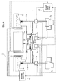
- a fuel supply apparatus 1 of the embodiment shown in an explanatory diagram of Fig. 1 supplies fuel from fuel tanks 3a to 3c in the fuselage and both wings to gas turbine engines (hereinafter abbreviated as "engines”) 5a and 5b in the both wings in an aircraft that is not shown.
- engines gas turbine engines
- the fuel supply apparatus 1 has: first to fourth pump units 7a to 7d that boost and pressurize fuel of the fuel tanks 3a to 3c, and supply it to the engines 5a and 5b; and an aircraft digital control device (an airframe computer, such as a flight computer) 15 on an airframe side that controls operations of the respective pump units 7a to 7d.
- an aircraft digital control device an airframe computer, such as a flight computer
- Remaining fuel amounts of the respective fuel tanks 3a to 3c are detected by sensors 3d to 3f.
- the detected remaining fuel amounts of the respective fuel tanks 3a to 3c are notified to the airframe computer 15, and also displayed on a flight deck panel 17 of a cockpit.
- Operation states of the first to fourth pump units 7a to 7d are also displayed on the flight deck panel 17.
- the first pump unit 7a and the second pump unit 7b supply fuel to a left-wing engine (a first engine) 5a.
- the first pump unit 7a is connected to a check valve 9a of the fuselage fuel tank 3a by a left central fuel flow passage 11a.
- the second pump unit 7b is connected to a check valve 9b of the left-wing fuel tank 3b by a left main fuel flow passage 11b.
- the third pump unit 7c and the fourth pump unit 7d supply fuel to a right-wing engine (a second engine) 5b.
- the third pump unit 7c is connected to a check valve 9c of the fuselage fuel tank 3a by a right central fuel flow passage 11c.
- the fourth pump unit 7d is connected to a check valve 9d of the right-wing fuel tank 3c by a right main fuel flow passage 11d.
- the right and left main fuel flow passages 11b and 11d are connected to each other by a central communication flow passage 11e.
- the central communication flow passage 11e enables flow of the fuel from the left main fuel flow passage 11b to the right main fuel flow passage 11d, and flow of the fuel from the right main fuel flow passage 11d to the left main fuel flow passage 11b.
- the central communication flow passage 11e makes it possible to supply the fuel of the left-wing fuel tank 3b to the fourth pump unit 7d, and to supply the fuel of the right-wing fuel tank 3c to the second pump unit 7b.
- the left central fuel flow passage 11a is connected to the left-wing fuel tank 3b through a check valve 9e and a left communication flow passage 11f.
- the right central fuel flow passage 11c is connected to the right-wing fuel tank 3c through a check valve 9f and a right communication flow passage 11g.
- the left communication flow passage 11f is configured so that a pressure loss is higher than in the left central fuel flow passage 11a. Accordingly, while the fuel remains in the fuselage fuel tank 3a, the fuel from the fuselage fuel tank 3a is supplied to the first pump unit 7a in priority to the fuel from the left-wing fuel tank 3b. In order to make the pressure loss of the left communication flow passage 11f higher than that of the central fuel flow passage 11a, for example, a diameter of the left communication flow passage 11f may just be made smaller than a diameter of the central fuel flow passage 11a.
- the right communication flow passage 11g is configured so that a pressure loss is higher than in the right central fuel flow passage 11c. Accordingly, while fuel remains in the fuselage fuel tank 3a, the fuel from the fuselage fuel tank 3a is supplied to the third pump unit 7c in priority to the fuel from the right-wing fuel tank 3c.
- a point closer to the fuselage fuel tank 3a than a connection point of the left communication flow passage 11f of the left central fuel flow passage 11a is connected to a suction port of a first ejector pump 13a.
- a boost pressure of the fuel by the third pump unit 7c is applied to a supply port of the first ejector pump 13a during an on-state of the third pump unit 7c.
- a discharge port of the first ejector pump 13a is connected to the left main fuel flow passage 11b through a left transfer flow passage 11h.
- a point closer to the fuselage fuel tank 3a than a connection point of the right communication flow passage 11g of the right central fuel flow passage 11c is connected to a suction port of a second ej ector pump 13b.
- a boost pressure of the fuel by the first pump unit 7a is applied to a supply port of the second ejector pump 13b during an on-state of the first pump unit 7a.
- a discharge port of the second ejector pump 13b is connected to the right main fuel flow passage 11d through a right transfer flow passage 11i.
- the first to fourth pump units 7a to 7d each have a booster 20 that boosts fuel supplied to a corresponding engine, and a measuring unit 30 that measures a supply amount of the fuel to the corresponding engine as shown in an explanatory diagram of Fig. 2 .
- the booster 20 has: a gear pump 22 that discharges fuel taken in from the fuel tanks 3a to 3c by a low-pressure pump (a centrifugal pump) 21 and boosted; an electric motor 23 that rotationally drives the low-pressure pump 21 and the gear pump 22; a motor controller 24 that controls the rotational speed of the electric motor 23; and a relief valve (a safety valve) 25 connected in parallel to the gear pump 22.
- the gear pump 22 is a well-known fixed displacement pump, and a discharge flow rate of the fuel by the gear pump 22 is proportional to the rotational speed of the gear pump 22.
- the motor controller 24 has a memory (not shown). A profile indicating a correlation characteristic of the rotational speed of the gear pump 22 proportional to the rotational speed of the electric motor 23 and a discharge flow rate of the fuel (a profile of the rotational speed to flow rate characteristic) is stored in the memory. In addition, the motor controller 24 receives a fuel flow demand of the fuel from the airframe computer 15 by means of a command signal. Additionally, the motor controller 24 obtains from the profile the rotational speed of the gear pump 22 corresponding to the fuel flow demand, determines the rotational speed of the electric motor 23 for rotationally driving the gear pump 22 at the rotational speed, and controls the rotational speed of the electric motor 23 to be the determined rotational speed.
- the measuring unit 30 has: a fixed orifice 31; a pressurizing valve 32 provided in parallel to the fixed orifice 31; and a differential pressure gauge 34 that measures a differential pressure between a front and a rear (an upstream side and a downstream side) of a parallel flow passage 33 of the fixed orifice 31 and the pressurizing valve 32.
- the fixed orifice 31 has an orifice with a fixed flow passage cross-sectional area, and when a discharge flow rate of the fuel by the gear pump 22 exceeds a set value, the pressurizing valve 32 opens at a valve opening degree according to the discharge flow rate.
- the set value means a flow rate of the fuel that passes through the fixed orifice 31. Accordingly, the flow rate of the fuel that passes through the parallel flow passage 33 becomes not more than a passing flow rate (the set value) of the fixed orifice 31 at the time of valve closing of the pressurizing valve 32, and it becomes a total value of the passing flow rate (the set value) of the fixed orifice 31 and a flow rate that passes through the pressurizing valve 32 at the time of valve opening of the pressurizing valve 32.
- the passing flow rate (the set value) of the fixed orifice 31 is adjusted to a flow rate slightly exceeding a flow rate of the fuel needed at the time of ignition (at the time of engine start) of the respective left-wing and right-wing engines 5a and 5b each having a fuel nozzle 5c.
- a fuel passing area in the parallel flow passage 33 is determined only by the fixed orifice 31 with good accuracy in a range in which a discharge flow rate of the fuel by the gear pump 22 is not less than the set value and less than a flow rate at which the pressurizing valve 32 opens.
- the fuel of the flow amount at the time of ignition of the engines 5a and 5b that requires accuracy can be accurately supplied to the fuel nozzle 5c.
- shut-off valve 26 provided in parallel to the relief valve 25 of the booster 20 is opened by a shut-off signal output by a controller that is not shown based on the command signal from the airframe computer 15.
- the fuel supplied from the booster 20 to the measuring unit 30 is recirculated between the low-pressure pump 21 and the gear pump 22, and thereby the fuel supply to the fuel nozzle 5c can be stopped.
- stop (shut-off) of the fuel supply to the fuel nozzle 5c can be achieved also by stopping rotational drive of the gear pump 22 by the electric motor 23.
- the gear pump 22 rotates due to inertia for a while even though the electric motor 23 is stopped, a small amount of fuel passes through the fixed orifice 31 until the rotation of the gear pump 22 stops even though the pressurizing valve 32 closes.
- a drain passage 32a that communicates with an atmospheric pressure is provided in the pressurizing valve 32, the small amount of fuel that has passed through the fixed orifice 31 is made to flow through the drain passage 32a instead of the fuel nozzle 5c in a high-pressure state by rotation of the gas turbine engine and, for example, it may be made to return to the fuel tanks 3a to 3c.
- the above-mentioned drain passage 32a is provided in the pressurizing valve 32, thereby a supply stop system of the fuel to the gas turbine engine is made to be redundant, and it can be used as a backup when malfunction occurs in a system of the shut-off valve 26 of the booster 20.
- the shut-off valve 26 may be omitted, and a shut-off system of the fuel may include only the drain passage 32a.
- the drain passage 32a of the pressurizing valve 32 may be omitted.
- the differential pressure between the front and the rear (the upstream side and the downstream side) of the parallel flow passage 33 measured by the differential pressure gauge 34 is fed back to the motor controller 24.
- the motor controller 24 detects an actual flow rate of the fuel that passes through the parallel flow passage 33 from the differential pressure measured by the differential pressure gauge 34. Additionally, when the detected actual flow rate of the fuel does not coincide with the fuel flow demand by the command signal from the airframe computer 15 (except for non-coincidence within an allowable error range), the motor controller 24 updates the profile stored in the memory.
- the profile to be updated can be obtained by multiplying a discharge flow rate of the fuel corresponding to the rotational speed of the gear pump 22 of the profile currently stored in the memory by a ratio of the actual flow rate of the fuel calculated by the motor controller 24 to the fuel flow demand.
- a plurality of sets of the rotational speed of the gear pump 22 and the actual flow rate of the fuel calculated from a measurement value of the differential pressure gauge 34 may be obtained, and the correlation characteristic of the rotational speed of the gear pump 22 and the discharge flow rate of the fuel may be obtained again.
- the rotational speed of the gear pump 22 corresponding to the fuel flow demand by the command signal from the airframe computer 15 is obtained from the updated profile by the motor controller 24, and the rotational speed of the electric motor 23 for rotationally driving the gear pump 22 at the obtained rotational speed is determined.
- the rotational speed of the electric motor 23 is then controlled to be the determined rotational speed by the motor controller 24.
- the actual flow rate of the fuel is detected by the motor controller 24 in the first to fourth pump units 7a to 7d. Additionally, when the fuel flow demand and the actual flow rate of the fuel become non-coincident with each other, the motor controller 24 updates the profile, which has been stored in the memory, of the correlation characteristic of the rotational speed of the gear pump 22 and the discharge flow rate of the fuel. When the profile is then updated, the rotational speed of the electric motor 23 determined by the motor controller 24 changes corresponding to a same fuel flow demand.
- the change is grasped based on the actual flow rate of the fuel detected by the motor controller 24 from a measurement result of the differential pressure gauge 34, and the rotational speed of the gear pump 22 proportional to the rotational speed (a control value) of the electric motor 23 at that time.
- the rotational speed of the gear pump 22 and the electric motor 23 corresponding to the fuel flow demand of the fuel is determined with reference to the profile of the correlation characteristic of the rotational speed of the gear pump 22 and the discharge flow rate of the fuel. For this reason, control for controlling the fuel supplied to the gas turbine engine to be the fuel flow demand is achieved by open-loop control that only updates the profile.
- a fuel supply amount is controlled to be the fuel flow demand with a simple configuration without complicating a configuration of a control system as in a case of always adjusting the rotational speed of the gear pump 22 and the electric motor 23 by feedback control by a closed loop.
- maintenance information that promotes maintenance or exchange of the gear pump 22 may be output and provided to the airframe side (an outside), with having updated the profile being used as a trigger.
- coincidence/non-coincidence of the fuel flow demand and the actual flow rate, a gap thereof, etc. may be output and provided to the airframe side as pump performance trend information, regardless of the presence/absence of updating of the profile.
- the first to fourth pump units 7a to 7d configured as described above have a capability of measuring and supplying at least half fuel of a maximum flow rate consumed by the left-wing engine 5a or the right-wing engine 5b, respectively.
- the first to fourth pump units 7a to 7d are turned on and off by control performed by the airframe computer 15 based on operation by a pilot of a control panel not shown provided at the flight deck panel 17 performed, or by control automatically performed by the airframe computer 15 based on a detection result by the sensor etc.
- one of the control by the airframe computer 15 based on the pilot's operation and the automatic control by the airframe computer 15 based on the detection result by the sensor etc. can be used as a backup. In that case, it is arbitrary which one is used as the backup. In addition, only either one control may be performed without providing the backup.
- the airframe computer 15 of the embodiment functions also as a switching unit that selectively switches the pump units 7a to 7d that supply fuel to the respective engines 5a and 5b, respectively.
- the first to fourth pump units 7a to 7d are all turned on at the time of takeoff when fuel consumption by the engines 5a and 5b in the both wings becomes a maximum as shown in Fig. 1 .
- fuel taken in from the fuselage fuel tank 3a through the left central fuel flow passage 11a by the first pump unit 7a, and fuel taken in from the fuel tanks 3b and 3c in the both wings through the right and left main fuel flow passages 11b and 11d and the central communication flow passage 11e by the second pump unit 7b are supplied to the left-wing engine 5a.
- the fuel taken in from the fuselage fuel tank 3a through the left central fuel flow passage 11a by the first pump unit 7a is supplied to the left-wing engine 5a.
- the fuel taken in from the fuselage fuel tank 3a through the right central fuel flow passage 11c by the third pump unit 7c is supplied to the right-wing engine 5b.
- a boost pressure of the fuel generated in the low-pressure pump 21 (refer to Fig. 2 ) of the third pump unit 7c is applied to the supply port of the first ejector pump 13a.
- a boost pressure of the fuel generated in the low-pressure pump 21 (refer to Fig. 2 ) of the first pump unit 7a is applied to the supply port of the second ejector pump 13b.
- the fuel of the fuselage fuel tank 3a connected to the suction ports of the first and second ejector pumps 13a and 13b is not supplied to the right main fuel flow passage 11d and the left main fuel flow passage 11b by the first and second ejector pumps 13a and 13b in which the boost pressures of the fuel have been applied to their supply ports from the third and first pump units 7c and 7a.
- the fuel taken in from the fuel tanks 3b and 3c in the both wings through the right and left main fuel flow passages 11b and 11d and the central communication flow passage 11e by the second pump unit 7b and the fourth pump unit 7d is supplied to the engines 5a and 5b in the both wings, respectively.
- the fuel cannot be supplied from the fuselage fuel tank 3a to the left-wing engine 5a through the left central fuel flow passage 11a.
- the second pump unit 7b is turned on instead of the first pump unit 7a as shown in an explanatory diagram of Fig. 5 .
- the second pump unit 7b supplies to the left-wing engine 5a the fuel taken in from the fuel tanks 3b and 3c in the both wings through the right and left main fuel flow passages 11b and 11d and the central communication flow passage 11e.
- the fuel taken in from the fuselage fuel tank 3a through the right central fuel flow passage 11c by the third pump unit 7c has been supplied to the right-wing engine 5b. Consequently, the boost pressure of the fuel generated in the low-pressure pump 21 (refer to Fig. 2 ) of the third pump unit 7c is applied to the supply port of the first ejector pump 13a.
- the fuel of the fuselage fuel tank 3a supplied to the left main fuel flow passage 11b by the first ejector pump 13a is supplied to the left-wing engine 5a by the second pump unit 7b together with the fuel taken in from the fuel tanks 3b and 3c in the both wings.
- the fourth pump unit 7d is turned on instead of the third pump unit 7c.
- the fourth pump unit 7d supplies to the right-wing engine 5b the fuel taken in from the fuel tanks 3b and 3c in the both wings through the right and left main fuel flow passages 11b and 11d and the central communication flow passage 11e.
- the first pump unit 7a has been turned on in order to supply the fuel of the fuselage fuel tank 3a to the left-wing engine 5a. Accordingly, the boost pressure of the fuel generated in the low-pressure pump 21 (refer to Fig. 2 ) of the first pump unit 7a is applied to the supply port of the second ejector pump 13b. In addition, flow of the fuel has been generated in the right main fuel flow passage 11d by turning-on of the fourth pump unit 7d.
- the fuel of the fuselage fuel tank 3a connected to the suction port of the second ejector pump 13b through the right central fuel flow passage 11c is supplied to the right main fuel flow passage 11d through the right transfer flow passage 11i by the second ejector pump 13b in which the boost pressure of the fuel has been applied to its supply port from the first pump unit 7a.
- the fuel of the fuselage fuel tank 3a supplied to the right main fuel flow passage 11d by the second ejector pump 13b is supplied to the right-wing engine 5b by the fourth pump unit 7d together with the fuel taken in from the fuel tanks 3b and 3c in the both wings.
- remaining fuel of the fuselage fuel tank 3a is supplied to the left-wing engine 5a and the right-wing engine 5b together using the first ejector pump 13a and the second ejector pump 13b, and thereby a reduction of a fuel supply amount of the fuselage fuel tank 3a to the left-wing engine 5a and the right-wing engine 5b, which is due to failure of the first pump unit 7a and the third pump unit 7c, can be mitigated.
- the fuel of the fuselage fuel tank 3a can be continued to be consumed in priority to the fuel of the fuel tanks 3b and 3c in the both wings.
- the first pump unit 7a is turned on instead of the second pump unit 7b as shown in an explanatory diagram of Fig. 6 .
- the fuselage fuel tank 3a is already empty, fuel is supplied from the left-wing fuel tank 3b to the first pump unit 7a through the check valve 9e and the left communication flow passage 11f with higher pressure losses than the left central fuel flow passage 11a.
- the first pump unit 7a then supplies to the left-wing engine 5a the fuel taken in from the left-wing fuel tank 3b.
- the boost pressure of the fuel generated in the low-pressure pump 21 (refer to Fig. 2 ) of the first pump unit 7a is applied to the supply port of the second ejector pump 13b.
- the flow of the fuel has been generated in the right main fuel flow passage 11d by turning-on of the fourth pump unit 7d.
- the fuselage fuel tank 3a connected to the suction port of the second ejector pump 13b through the right central fuel flow passage 11c is empty.
- the fuel of the right-wing fuel tank 3c is supplied to the suction port of the second ejector pump 13b through the check valve 9f and the right communication flow passage 11g with higher pressure losses than the right central fuel flow passage 11c. Accordingly, the fuel from the right-wing fuel tank 3c is supplied to the right main fuel flow passage 11d through the right transfer flow passage 11i by the second ejector pump 13b in which the boost pressure of the fuel has been applied to its supply port from the first pump unit 7a.
- the fuel of the right-wing fuel tank 3c supplied to the right main fuel flow passage 11d by the second ejector pump 13b is supplied to the right-wing engine 5b by the fourth pump unit 7d together with the fuel directly taken in from the right-wing fuel tank 3c through the right main fuel flow passage 11d.
- the third pump unit 7c is turned on instead of the fourth pump unit 7d.
- the third pump unit 7c supplies to the right-wing engine 5b the fuel taken in from the right-wing fuel tank 3c through the check valve 9f and the right communication flow passage 11g with the higher pressure losses than the right central fuel flow passage 11c.
- the third pump unit 7c has been turned on in order to supply the fuel of the fuselage fuel tank 3a to the right-wing engine 5b. Accordingly, the boost pressure of the fuel generated in the low-pressure pump 21 (refer to Fig. 2 ) of the third pump unit 7c is applied to the supply port of the first ejector pump 13a. In addition, the flow of the fuel has been generated in the left main fuel flow passage 11b by turning-on of the first pump unit 7a. However, the fuselage fuel tank 3a connected to the suction port of the first ejector pump 13a through the left central fuel flow passage 11a is empty.
- the fuel of the left-wing fuel tank 3b is supplied to the suction port of the first ejector pump 13a through the check valve 9e and the left communication flow passage 11f with the higher pressure losses than the left central fuel flow passage 11a. Accordingly, the fuel from the left-wing fuel tank 3b is supplied to the left main fuel flow passage 11b through the left transfer flow passage 11h by the first ejector pump 13a in which the boost pressure of the fuel has been applied to its supply port from the third pump unit 7c.
- the fuel of the left-wing fuel tank 3b supplied to the left main fuel flow passage 11b by the first ejector pump 13a is supplied to the left-wing engine 5a by the second pump unit 7b together with the fuel directly taken in from the left-wing fuel tank 3b through the left main fuel flow passage 11b.
- two systems of the first pump unit 7a and the third pump unit 7c that supply the fuel of the fuselage fuel tank 3a, and the second pump unit 7b and the fourth pump unit 7d that supply the fuel of the fuel tanks 3b and 3c in the both right and left wings are provided corresponding to the left-wing engine 5a and the right-wing engine 5b, respectively.
- the first pump unit 7a is selected as the pump unit that supplies fuel to the left-wing engine 5a
- the fuel from the fuselage fuel tank 3a is supplied to the left-wing engine 5a by the first pump unit 7a.
- the second pump unit 7b is selected as the pump unit that supplies fuel to the left-wing engine 5a
- the fuel from the fuel tanks 3b and 3c in the both wings is supplied to the left-wing engine 5a by the second pump unit 7b.
- the fuel from the fuselage fuel tank 3a is supplied to the right-wing engine 5b by the third pump unit 7c.
- the fourth pump unit 7d is selected as the pump unit that supplies fuel to the right-wing engine 5b, the fuel from the fuel tanks 3b and 3c in the both wings is supplied to the right-wing engine 5b by the fourth pump unit 7d.
- a supply source of the fuel to be supplied to the left-wing engine 5a and the right-wing engine 5b can be switched by switching of the pump units to be turned on. That is, when the pump units used for fuel supply to the engines 5a and 5b are switched from the first pump unit 7a and the third pump unit 7c to the second pump unit 7b and the fourth pump unit 7d, fuel consumed in the engines 5a and 5b is switched from the fuel of the fuselage fuel tank 3a to the fuel of the fuel tanks 3b and 3c in the both wings.
- the second pump unit 7b and the fourth pump unit 7d supply the fuel of the fuel tanks 3b and 3c in the both wings to the engines 5a and 5b
- the fuel of the fuel tanks 3b and 3c in the both wings is equally consumed in the engines 5a and 5b, and the fuel of the fuel tanks 3b and 3c of one of the wings is not consumed unevenly in the engines 5a and 5b. Accordingly, it can be achieved by simple configuration and operation to consume the fuel of the fuel tanks 3a to 3c in the fuselage and the both wings in order, and to equalize amounts of fuel consumption of the fuel tanks 3b and 3c in the both wings.
- the fuel of the left-wing fuel tank 3b or the right-wing fuel tank 3c can be supplied to the left-wing engine 5a or the right-wing engine 5b instead of the fuel of the fuselage fuel tank 3a by the second pump unit 7b and the fourth pump unit 7d.
- a configuration may be omitted in which the fuel of the fuselage fuel tank 3a can be supplied to the left-wing engine 5a or the right-wing engine 5b by the first ejector pump 13a and the second ejector pump 13b at the time of failure of the first pump unit 7a or the third pump unit 7c.
- the fuel of the fuselage fuel tank 3a can be continued to be consumed in priority to the fuel of the fuel tanks 3b and 3c in the both wings, even though the first pump unit 7a or the third pump unit 7c breaks down.
- the fuel of the fuselage fuel tank 3a cannot be supplied to the engines 5a and 5b because of the stop of the first pump unit 7a or the third pump unit 7c due to failure etc., and switching is performed so that fuel is supplied from the fuel tanks 3b and 3c in the both wings to the engines 5a and 5b, fuel consumption of the fuselage fuel tank 3a decreases as much as a fuel amount that is not supplied to the engines 5a and 5b.
- the fuel of the fuselage fuel tank 3a is supplied to the left-wing engine 5a by the second pump unit 7b using the first ejector pump 13a, if the third pump unit 7c has not stopped.
- the fuel of the fuselage fuel tank 3a is supplied to the right-wing engine 5b by the fourth pump unit 7d using the second ejector pump 13b, if the first pump unit 7a has not stopped.
- the engine 5a (or 5b) in which the fuel supply source has been switched to the fuel tanks 3b and 3c in the both wings due to the stop of the pump unit is made to continue to consume the fuel of the fuselage fuel tank 3a in the state where the fuel remains in the fuselage fuel tank 3a, and thereby change of the order of consuming the fuel between the fuselage fuel tank 3a, and the fuel tanks 3b and 3c in the both wings can be suppressed.
- the present invention can be widely applied to an aircraft that supplies fuel to an engine as a propulsion device regardless of a military aircraft or a civil aircraft, or regardless of a passenger aircraft or a cargo aircraft.
Landscapes
- Engineering & Computer Science (AREA)
- Chemical & Material Sciences (AREA)
- Combustion & Propulsion (AREA)
- Aviation & Aerospace Engineering (AREA)
- Mechanical Engineering (AREA)
- General Engineering & Computer Science (AREA)
- Automation & Control Theory (AREA)
- Cooling, Air Intake And Gas Exhaust, And Fuel Tank Arrangements In Propulsion Units (AREA)
Applications Claiming Priority (2)
| Application Number | Priority Date | Filing Date | Title |
|---|---|---|---|
| JP2013179226A JP6131785B2 (ja) | 2013-08-30 | 2013-08-30 | 航空機エンジンの燃料供給装置 |
| PCT/JP2014/071496 WO2015029805A1 (fr) | 2013-08-30 | 2014-08-15 | Dispositif d'alimentation en combustible d'un moteur d'aéronef |
Publications (3)
| Publication Number | Publication Date |
|---|---|
| EP3040277A1 true EP3040277A1 (fr) | 2016-07-06 |
| EP3040277A4 EP3040277A4 (fr) | 2017-05-24 |
| EP3040277B1 EP3040277B1 (fr) | 2020-01-08 |
Family
ID=52586373
Family Applications (1)
| Application Number | Title | Priority Date | Filing Date |
|---|---|---|---|
| EP14839879.5A Active EP3040277B1 (fr) | 2013-08-30 | 2014-08-15 | Dispositif d'alimentation en combustible pour moteur d'aéronef |
Country Status (5)
| Country | Link |
|---|---|
| US (1) | US10358980B2 (fr) |
| EP (1) | EP3040277B1 (fr) |
| JP (1) | JP6131785B2 (fr) |
| CA (1) | CA2922020C (fr) |
| WO (1) | WO2015029805A1 (fr) |
Cited By (6)
| Publication number | Priority date | Publication date | Assignee | Title |
|---|---|---|---|---|
| EP3712415A4 (fr) * | 2017-11-16 | 2021-08-18 | IHI Corporation | Dispositif de commande d'alimentation en carburant |
| EP3763927A4 (fr) * | 2018-03-08 | 2021-11-17 | Ihi Corporation | Dispositif de commande d'alimentation en carburant |
| WO2022195224A1 (fr) * | 2021-03-17 | 2022-09-22 | Safran Helicopter Engines | Systeme de pompage et de dosage d'un fluide pour turbomachine et procede de pilotage d'un tel systeme |
| FR3120919A1 (fr) * | 2021-03-17 | 2022-09-23 | Safran Helicopter Engines | Procede de pilotage d’un systeme de pompage et de dosage d’un fluide pour turbomachine |
| FR3120920A1 (fr) * | 2021-03-17 | 2022-09-23 | Safran Helicopter Engines | Systeme de pompage et de dosage d’un fluide pour turbomachine et procede de pilotage d’un tel systeme |
| US11761382B2 (en) | 2017-12-14 | 2023-09-19 | Ihi Corporation | Fuel supply device |
Families Citing this family (9)
| Publication number | Priority date | Publication date | Assignee | Title |
|---|---|---|---|---|
| US20190002087A1 (en) * | 2017-06-29 | 2019-01-03 | XP Services, Inc. | Automated aircraft fuel management and transfer system |
| FR3082311B1 (fr) * | 2018-06-07 | 2020-07-03 | Airbus Operations | Procede et systeme d'acquisition de caracteristiques de carburant a bord d'un aeronef |
| US11485513B2 (en) * | 2018-10-05 | 2022-11-01 | Parker-Hannifin Corporation | Fuel pump override control method |
| JP7471776B2 (ja) | 2019-02-18 | 2024-04-22 | 三菱重工業株式会社 | ジェットエンジン |
| JP2022139821A (ja) * | 2021-03-12 | 2022-09-26 | 本田技研工業株式会社 | 燃料供給システムおよび燃料供給方法 |
| EP4305653A1 (fr) | 2021-03-12 | 2024-01-17 | Essex Industries, Inc. | Commutateur à bascule |
| US11688568B2 (en) | 2021-03-15 | 2023-06-27 | Essex Industries, Inc. | Five-position switch |
| US11976599B1 (en) * | 2022-12-20 | 2024-05-07 | Hamilton Sundstrand Corporation | Pumps with backup capability |
| US12025084B1 (en) | 2023-06-12 | 2024-07-02 | Hamilton Sundstrand Corporation | In-tank ejector pump |
Family Cites Families (25)
| Publication number | Priority date | Publication date | Assignee | Title |
|---|---|---|---|---|
| US2440262A (en) * | 1942-02-16 | 1948-04-27 | Ralph E Grey | Fuel supply system for aircraft |
| US2580467A (en) * | 1945-05-15 | 1952-01-01 | Samiran David | Multitank aircraft fuel system |
| US2516150A (en) * | 1945-08-01 | 1950-07-25 | Samiran David | Continuous flow multiple tank fuel system |
| US3319570A (en) * | 1964-01-02 | 1967-05-16 | Boeing Co | Fuel feeding systems |
| GB1128377A (en) * | 1966-01-31 | 1968-09-25 | British Aircraft Corp Ltd | Improvements relating to aircraft fuel supply arrangements |
| FR1484704A (fr) * | 1966-04-04 | 1967-06-16 | Snecma | Mélangeur variable pour installation à grande variation de débit |
| US3627239A (en) * | 1970-04-20 | 1971-12-14 | Gen Electric | Aircraft engine fuel system |
| US4591115A (en) * | 1984-10-18 | 1986-05-27 | The United States Of America As Represented By The Secretary Of The Navy | Automatic/manual fuel tank supply balance system |
| US4932609A (en) * | 1989-02-27 | 1990-06-12 | United Technologies Corporation | Fuel transfer system for aircraft |
| US5321945A (en) * | 1990-04-02 | 1994-06-21 | Honeywell Inc. | Apparatus for controlling fuel transfers in a distributed fuel tank system |
| EP0670264A1 (fr) * | 1994-03-02 | 1995-09-06 | Daimler-Benz Aerospace Aktiengesellschaft | Système d'alimentation en combustible |
| US5555873A (en) * | 1995-02-16 | 1996-09-17 | Nolen; Jay A. | Fuel tank switching apparatus |
| US6126111A (en) * | 1998-07-08 | 2000-10-03 | The United States Of America As Represented By The Administrator Of The National Aeronautics And Space Administration | Emergency flight control system using one engine and fuel transfer |
| US6125882A (en) * | 1998-12-16 | 2000-10-03 | Kong; Carl Cheung Tung | Fluid transfer system |
| JP3820949B2 (ja) | 2001-10-02 | 2006-09-13 | 日産自動車株式会社 | 移送用ポンプ付き燃料供給装置 |
| US6736354B2 (en) * | 2002-02-04 | 2004-05-18 | Honda Giken Kogyo Kabushiki Kaisha | Airplane fuel supply system and airplane wing pipeline assembly method |
| US7458543B2 (en) * | 2005-06-10 | 2008-12-02 | The Boeing Company | Aerial refueling system |
| US7337795B2 (en) | 2005-10-17 | 2008-03-04 | The Boeing Company | Fuel balancing system |
| US7540141B2 (en) * | 2005-12-13 | 2009-06-02 | Hamilton Sundstrand Corporation | Smart fuel control system |
| EP2074027B1 (fr) | 2006-10-20 | 2011-07-20 | The Boeing Company | Système à équilibrage de carburant |
| FR2934321B1 (fr) * | 2008-07-25 | 2013-09-27 | Hispano Suiza Sa | Regulation du debit de carburant preleve dans un circuit carburant d'un aeronef propulse par un moteur. |
| US8226040B2 (en) * | 2008-08-25 | 2012-07-24 | Embraer S.A. | Continuous fuel management system for automatic control of aircraft center of gravity |
| US9205913B2 (en) * | 2010-09-09 | 2015-12-08 | Groen Brothers Aviation, Inc. | Rotorcraft, dynamic, CG management apparatus and method |
| US20120324905A1 (en) * | 2011-06-27 | 2012-12-27 | Behzad Hagshenas | Apu fuel system and method |
| JP5799642B2 (ja) | 2011-08-01 | 2015-10-28 | 株式会社Ihi | ガスタービンエンジン用の燃料供給システム |
-
2013
- 2013-08-30 JP JP2013179226A patent/JP6131785B2/ja active Active
-
2014
- 2014-08-15 EP EP14839879.5A patent/EP3040277B1/fr active Active
- 2014-08-15 CA CA2922020A patent/CA2922020C/fr active Active
- 2014-08-15 WO PCT/JP2014/071496 patent/WO2015029805A1/fr active Application Filing
-
2016
- 2016-02-23 US US15/050,800 patent/US10358980B2/en active Active
Non-Patent Citations (1)
| Title |
|---|
| See references of WO2015029805A1 * |
Cited By (8)
| Publication number | Priority date | Publication date | Assignee | Title |
|---|---|---|---|---|
| EP3712415A4 (fr) * | 2017-11-16 | 2021-08-18 | IHI Corporation | Dispositif de commande d'alimentation en carburant |
| US11352959B2 (en) | 2017-11-16 | 2022-06-07 | Ihi Corporation | Fuel supply control device |
| US11761382B2 (en) | 2017-12-14 | 2023-09-19 | Ihi Corporation | Fuel supply device |
| EP3763927A4 (fr) * | 2018-03-08 | 2021-11-17 | Ihi Corporation | Dispositif de commande d'alimentation en carburant |
| US11365683B2 (en) | 2018-03-08 | 2022-06-21 | Ihi Corporation | Fuel supply control device |
| WO2022195224A1 (fr) * | 2021-03-17 | 2022-09-22 | Safran Helicopter Engines | Systeme de pompage et de dosage d'un fluide pour turbomachine et procede de pilotage d'un tel systeme |
| FR3120919A1 (fr) * | 2021-03-17 | 2022-09-23 | Safran Helicopter Engines | Procede de pilotage d’un systeme de pompage et de dosage d’un fluide pour turbomachine |
| FR3120920A1 (fr) * | 2021-03-17 | 2022-09-23 | Safran Helicopter Engines | Systeme de pompage et de dosage d’un fluide pour turbomachine et procede de pilotage d’un tel systeme |
Also Published As
| Publication number | Publication date |
|---|---|
| US10358980B2 (en) | 2019-07-23 |
| EP3040277B1 (fr) | 2020-01-08 |
| EP3040277A4 (fr) | 2017-05-24 |
| CA2922020C (fr) | 2017-04-25 |
| WO2015029805A1 (fr) | 2015-03-05 |
| CA2922020A1 (fr) | 2015-03-05 |
| US20160169112A1 (en) | 2016-06-16 |
| JP2015047902A (ja) | 2015-03-16 |
| JP6131785B2 (ja) | 2017-05-24 |
Similar Documents
| Publication | Publication Date | Title |
|---|---|---|
| US10358980B2 (en) | Fuel supply apparatus for aircraft engine | |
| US7591277B2 (en) | Fuel balancing system | |
| EP3232036B1 (fr) | Système de carburant à double pompe avec connexion de partage de pompe | |
| EP2074027B1 (fr) | Système à équilibrage de carburant | |
| US20050144957A1 (en) | Methods for operating gas turbine engines | |
| US20040159104A1 (en) | Methods for rotor overspeed and overboost protection | |
| US20140216037A1 (en) | Engine fuel control system | |
| US6742742B2 (en) | Device and process for regulating the power of the engines of a rotary wing multi-engine aircraft | |
| EP2578844B1 (fr) | Système de carburant de moteur d'avion | |
| JP2013231406A (ja) | ガスタービンエンジンの燃料供給装置 | |
| EP2808259B1 (fr) | Système duel de régulation de pression pour des opérations de ravitaillement aérien | |
| CN109763914B (zh) | 一种具有冗余功能的甲烷自生增压系统 | |
| US20210164399A1 (en) | Fluid supply system | |
| EP2612815B1 (fr) | Alimentation en carburant pour régime moteur maximal, l'alimentation en carburant impliquant une pompe d'appoint | |
| CN113236611A (zh) | 用于飞行器的发动机引气系统和引气控制方法 | |
| US20200378315A1 (en) | Fuel system with integrated thrust control malfunction protection and method | |
| US11485513B2 (en) | Fuel pump override control method | |
| RU2648479C1 (ru) | Система автоматического управления авиационного газотурбинного двигателя | |
| US20130309091A1 (en) | Oil supply system for a propeller turbine engine | |
| RU2500910C2 (ru) | Устройство для управления раходом топлива в газотурбинный двигатель | |
| CN113968339A (zh) | 一种可应急配平直升机旋翼反扭矩的环控系统及控制方法 | |
| JP2022071315A (ja) | 燃圧センサの異常検出装置 | |
| CN117157454A (zh) | 涡轮发动机的泵送和计量流体的系统及控制该系统的方法 | |
| CN105756784A (zh) | 螺旋桨反桨超转保护结构 |
Legal Events
| Date | Code | Title | Description |
|---|---|---|---|
| PUAI | Public reference made under article 153(3) epc to a published international application that has entered the european phase |
Free format text: ORIGINAL CODE: 0009012 |
|
| 17P | Request for examination filed |
Effective date: 20160330 |
|
| AK | Designated contracting states |
Kind code of ref document: A1 Designated state(s): AL AT BE BG CH CY CZ DE DK EE ES FI FR GB GR HR HU IE IS IT LI LT LU LV MC MK MT NL NO PL PT RO RS SE SI SK SM TR |
|
| AX | Request for extension of the european patent |
Extension state: BA ME |
|
| DAX | Request for extension of the european patent (deleted) | ||
| A4 | Supplementary search report drawn up and despatched |
Effective date: 20170425 |
|
| RIC1 | Information provided on ipc code assigned before grant |
Ipc: B64D 37/14 20060101AFI20170419BHEP |
|
| STAA | Information on the status of an ep patent application or granted ep patent |
Free format text: STATUS: EXAMINATION IS IN PROGRESS |
|
| 17Q | First examination report despatched |
Effective date: 20181016 |
|
| RIC1 | Information provided on ipc code assigned before grant |
Ipc: F02C 7/228 20060101ALN20190401BHEP Ipc: B64D 37/04 20060101AFI20190401BHEP Ipc: F02C 7/236 20060101ALN20190401BHEP Ipc: F04D 13/06 20060101ALN20190401BHEP Ipc: B64C 17/10 20060101ALN20190401BHEP Ipc: B64D 37/20 20060101ALI20190401BHEP Ipc: F02C 9/42 20060101ALN20190401BHEP Ipc: B64C 11/30 20060101ALN20190401BHEP Ipc: B64D 37/14 20060101ALI20190401BHEP |
|
| GRAP | Despatch of communication of intention to grant a patent |
Free format text: ORIGINAL CODE: EPIDOSNIGR1 |
|
| STAA | Information on the status of an ep patent application or granted ep patent |
Free format text: STATUS: GRANT OF PATENT IS INTENDED |
|
| INTG | Intention to grant announced |
Effective date: 20190522 |
|
| GRAJ | Information related to disapproval of communication of intention to grant by the applicant or resumption of examination proceedings by the epo deleted |
Free format text: ORIGINAL CODE: EPIDOSDIGR1 |
|
| STAA | Information on the status of an ep patent application or granted ep patent |
Free format text: STATUS: EXAMINATION IS IN PROGRESS |
|
| REG | Reference to a national code |
Ref country code: DE Ref legal event code: R079 Ref document number: 602014059832 Country of ref document: DE Free format text: PREVIOUS MAIN CLASS: B64D0037140000 Ipc: B64D0037040000 |
|
| GRAP | Despatch of communication of intention to grant a patent |
Free format text: ORIGINAL CODE: EPIDOSNIGR1 |
|
| STAA | Information on the status of an ep patent application or granted ep patent |
Free format text: STATUS: GRANT OF PATENT IS INTENDED |
|
| INTC | Intention to grant announced (deleted) | ||
| RIC1 | Information provided on ipc code assigned before grant |
Ipc: B64D 37/20 20060101ALI20190701BHEP Ipc: F04D 13/06 20060101ALN20190701BHEP Ipc: F02C 7/236 20060101ALN20190701BHEP Ipc: B64C 17/10 20060101ALN20190701BHEP Ipc: B64D 37/04 20060101AFI20190701BHEP Ipc: B64D 37/14 20060101ALI20190701BHEP Ipc: F02C 7/22 20060101ALN20190701BHEP Ipc: F02C 7/228 20060101ALN20190701BHEP Ipc: B64C 11/30 20060101ALN20190701BHEP Ipc: F02C 9/42 20060101ALN20190701BHEP |
|
| INTG | Intention to grant announced |
Effective date: 20190807 |
|
| GRAS | Grant fee paid |
Free format text: ORIGINAL CODE: EPIDOSNIGR3 |
|
| GRAA | (expected) grant |
Free format text: ORIGINAL CODE: 0009210 |
|
| STAA | Information on the status of an ep patent application or granted ep patent |
Free format text: STATUS: THE PATENT HAS BEEN GRANTED |
|
| RIN1 | Information on inventor provided before grant (corrected) |
Inventor name: OYORI, HITOSHI Inventor name: MORIOKA, NORIKO |
|
| AK | Designated contracting states |
Kind code of ref document: B1 Designated state(s): AL AT BE BG CH CY CZ DE DK EE ES FI FR GB GR HR HU IE IS IT LI LT LU LV MC MK MT NL NO PL PT RO RS SE SI SK SM TR |
|
| REG | Reference to a national code |
Ref country code: GB Ref legal event code: FG4D |
|
| REG | Reference to a national code |
Ref country code: CH Ref legal event code: EP |
|
| REG | Reference to a national code |
Ref country code: DE Ref legal event code: R096 Ref document number: 602014059832 Country of ref document: DE |
|
| REG | Reference to a national code |
Ref country code: IE Ref legal event code: FG4D |
|
| REG | Reference to a national code |
Ref country code: AT Ref legal event code: REF Ref document number: 1222396 Country of ref document: AT Kind code of ref document: T Effective date: 20200215 |
|
| REG | Reference to a national code |
Ref country code: NL Ref legal event code: MP Effective date: 20200108 |
|
| REG | Reference to a national code |
Ref country code: LT Ref legal event code: MG4D |
|
| PG25 | Lapsed in a contracting state [announced via postgrant information from national office to epo] |
Ref country code: NL Free format text: LAPSE BECAUSE OF FAILURE TO SUBMIT A TRANSLATION OF THE DESCRIPTION OR TO PAY THE FEE WITHIN THE PRESCRIBED TIME-LIMIT Effective date: 20200108 Ref country code: LT Free format text: LAPSE BECAUSE OF FAILURE TO SUBMIT A TRANSLATION OF THE DESCRIPTION OR TO PAY THE FEE WITHIN THE PRESCRIBED TIME-LIMIT Effective date: 20200108 Ref country code: NO Free format text: LAPSE BECAUSE OF FAILURE TO SUBMIT A TRANSLATION OF THE DESCRIPTION OR TO PAY THE FEE WITHIN THE PRESCRIBED TIME-LIMIT Effective date: 20200408 Ref country code: FI Free format text: LAPSE BECAUSE OF FAILURE TO SUBMIT A TRANSLATION OF THE DESCRIPTION OR TO PAY THE FEE WITHIN THE PRESCRIBED TIME-LIMIT Effective date: 20200108 Ref country code: RS Free format text: LAPSE BECAUSE OF FAILURE TO SUBMIT A TRANSLATION OF THE DESCRIPTION OR TO PAY THE FEE WITHIN THE PRESCRIBED TIME-LIMIT Effective date: 20200108 Ref country code: PT Free format text: LAPSE BECAUSE OF FAILURE TO SUBMIT A TRANSLATION OF THE DESCRIPTION OR TO PAY THE FEE WITHIN THE PRESCRIBED TIME-LIMIT Effective date: 20200531 |
|
| PG25 | Lapsed in a contracting state [announced via postgrant information from national office to epo] |
Ref country code: LV Free format text: LAPSE BECAUSE OF FAILURE TO SUBMIT A TRANSLATION OF THE DESCRIPTION OR TO PAY THE FEE WITHIN THE PRESCRIBED TIME-LIMIT Effective date: 20200108 Ref country code: SE Free format text: LAPSE BECAUSE OF FAILURE TO SUBMIT A TRANSLATION OF THE DESCRIPTION OR TO PAY THE FEE WITHIN THE PRESCRIBED TIME-LIMIT Effective date: 20200108 Ref country code: IS Free format text: LAPSE BECAUSE OF FAILURE TO SUBMIT A TRANSLATION OF THE DESCRIPTION OR TO PAY THE FEE WITHIN THE PRESCRIBED TIME-LIMIT Effective date: 20200508 Ref country code: HR Free format text: LAPSE BECAUSE OF FAILURE TO SUBMIT A TRANSLATION OF THE DESCRIPTION OR TO PAY THE FEE WITHIN THE PRESCRIBED TIME-LIMIT Effective date: 20200108 Ref country code: GR Free format text: LAPSE BECAUSE OF FAILURE TO SUBMIT A TRANSLATION OF THE DESCRIPTION OR TO PAY THE FEE WITHIN THE PRESCRIBED TIME-LIMIT Effective date: 20200409 Ref country code: BG Free format text: LAPSE BECAUSE OF FAILURE TO SUBMIT A TRANSLATION OF THE DESCRIPTION OR TO PAY THE FEE WITHIN THE PRESCRIBED TIME-LIMIT Effective date: 20200408 |
|
| REG | Reference to a national code |
Ref country code: DE Ref legal event code: R097 Ref document number: 602014059832 Country of ref document: DE |
|
| PG25 | Lapsed in a contracting state [announced via postgrant information from national office to epo] |
Ref country code: EE Free format text: LAPSE BECAUSE OF FAILURE TO SUBMIT A TRANSLATION OF THE DESCRIPTION OR TO PAY THE FEE WITHIN THE PRESCRIBED TIME-LIMIT Effective date: 20200108 Ref country code: SM Free format text: LAPSE BECAUSE OF FAILURE TO SUBMIT A TRANSLATION OF THE DESCRIPTION OR TO PAY THE FEE WITHIN THE PRESCRIBED TIME-LIMIT Effective date: 20200108 Ref country code: CZ Free format text: LAPSE BECAUSE OF FAILURE TO SUBMIT A TRANSLATION OF THE DESCRIPTION OR TO PAY THE FEE WITHIN THE PRESCRIBED TIME-LIMIT Effective date: 20200108 Ref country code: RO Free format text: LAPSE BECAUSE OF FAILURE TO SUBMIT A TRANSLATION OF THE DESCRIPTION OR TO PAY THE FEE WITHIN THE PRESCRIBED TIME-LIMIT Effective date: 20200108 Ref country code: ES Free format text: LAPSE BECAUSE OF FAILURE TO SUBMIT A TRANSLATION OF THE DESCRIPTION OR TO PAY THE FEE WITHIN THE PRESCRIBED TIME-LIMIT Effective date: 20200108 Ref country code: DK Free format text: LAPSE BECAUSE OF FAILURE TO SUBMIT A TRANSLATION OF THE DESCRIPTION OR TO PAY THE FEE WITHIN THE PRESCRIBED TIME-LIMIT Effective date: 20200108 Ref country code: SK Free format text: LAPSE BECAUSE OF FAILURE TO SUBMIT A TRANSLATION OF THE DESCRIPTION OR TO PAY THE FEE WITHIN THE PRESCRIBED TIME-LIMIT Effective date: 20200108 |
|
| PLBE | No opposition filed within time limit |
Free format text: ORIGINAL CODE: 0009261 |
|
| STAA | Information on the status of an ep patent application or granted ep patent |
Free format text: STATUS: NO OPPOSITION FILED WITHIN TIME LIMIT |
|
| REG | Reference to a national code |
Ref country code: AT Ref legal event code: MK05 Ref document number: 1222396 Country of ref document: AT Kind code of ref document: T Effective date: 20200108 |
|
| 26N | No opposition filed |
Effective date: 20201009 |
|
| PG25 | Lapsed in a contracting state [announced via postgrant information from national office to epo] |
Ref country code: AT Free format text: LAPSE BECAUSE OF FAILURE TO SUBMIT A TRANSLATION OF THE DESCRIPTION OR TO PAY THE FEE WITHIN THE PRESCRIBED TIME-LIMIT Effective date: 20200108 Ref country code: IT Free format text: LAPSE BECAUSE OF FAILURE TO SUBMIT A TRANSLATION OF THE DESCRIPTION OR TO PAY THE FEE WITHIN THE PRESCRIBED TIME-LIMIT Effective date: 20200108 |
|
| PG25 | Lapsed in a contracting state [announced via postgrant information from national office to epo] |
Ref country code: SI Free format text: LAPSE BECAUSE OF FAILURE TO SUBMIT A TRANSLATION OF THE DESCRIPTION OR TO PAY THE FEE WITHIN THE PRESCRIBED TIME-LIMIT Effective date: 20200108 Ref country code: PL Free format text: LAPSE BECAUSE OF FAILURE TO SUBMIT A TRANSLATION OF THE DESCRIPTION OR TO PAY THE FEE WITHIN THE PRESCRIBED TIME-LIMIT Effective date: 20200108 |
|
| PG25 | Lapsed in a contracting state [announced via postgrant information from national office to epo] |
Ref country code: MC Free format text: LAPSE BECAUSE OF FAILURE TO SUBMIT A TRANSLATION OF THE DESCRIPTION OR TO PAY THE FEE WITHIN THE PRESCRIBED TIME-LIMIT Effective date: 20200108 |
|
| REG | Reference to a national code |
Ref country code: CH Ref legal event code: PL |
|
| PG25 | Lapsed in a contracting state [announced via postgrant information from national office to epo] |
Ref country code: LI Free format text: LAPSE BECAUSE OF NON-PAYMENT OF DUE FEES Effective date: 20200831 Ref country code: LU Free format text: LAPSE BECAUSE OF NON-PAYMENT OF DUE FEES Effective date: 20200815 Ref country code: CH Free format text: LAPSE BECAUSE OF NON-PAYMENT OF DUE FEES Effective date: 20200831 |
|
| REG | Reference to a national code |
Ref country code: BE Ref legal event code: MM Effective date: 20200831 |
|
| PG25 | Lapsed in a contracting state [announced via postgrant information from national office to epo] |
Ref country code: BE Free format text: LAPSE BECAUSE OF NON-PAYMENT OF DUE FEES Effective date: 20200831 Ref country code: IE Free format text: LAPSE BECAUSE OF NON-PAYMENT OF DUE FEES Effective date: 20200815 |
|
| PG25 | Lapsed in a contracting state [announced via postgrant information from national office to epo] |
Ref country code: TR Free format text: LAPSE BECAUSE OF FAILURE TO SUBMIT A TRANSLATION OF THE DESCRIPTION OR TO PAY THE FEE WITHIN THE PRESCRIBED TIME-LIMIT Effective date: 20200108 Ref country code: MT Free format text: LAPSE BECAUSE OF FAILURE TO SUBMIT A TRANSLATION OF THE DESCRIPTION OR TO PAY THE FEE WITHIN THE PRESCRIBED TIME-LIMIT Effective date: 20200108 Ref country code: CY Free format text: LAPSE BECAUSE OF FAILURE TO SUBMIT A TRANSLATION OF THE DESCRIPTION OR TO PAY THE FEE WITHIN THE PRESCRIBED TIME-LIMIT Effective date: 20200108 |
|
| PG25 | Lapsed in a contracting state [announced via postgrant information from national office to epo] |
Ref country code: MK Free format text: LAPSE BECAUSE OF FAILURE TO SUBMIT A TRANSLATION OF THE DESCRIPTION OR TO PAY THE FEE WITHIN THE PRESCRIBED TIME-LIMIT Effective date: 20200108 Ref country code: AL Free format text: LAPSE BECAUSE OF FAILURE TO SUBMIT A TRANSLATION OF THE DESCRIPTION OR TO PAY THE FEE WITHIN THE PRESCRIBED TIME-LIMIT Effective date: 20200108 |
|
| PGFP | Annual fee paid to national office [announced via postgrant information from national office to epo] |
Ref country code: GB Payment date: 20230720 Year of fee payment: 10 |
|
| PGFP | Annual fee paid to national office [announced via postgrant information from national office to epo] |
Ref country code: FR Payment date: 20230720 Year of fee payment: 10 Ref country code: DE Payment date: 20230720 Year of fee payment: 10 |