EP3040256A1 - Radkasten eines kraftfahrzeuges - Google Patents
Radkasten eines kraftfahrzeuges Download PDFInfo
- Publication number
- EP3040256A1 EP3040256A1 EP15466023.7A EP15466023A EP3040256A1 EP 3040256 A1 EP3040256 A1 EP 3040256A1 EP 15466023 A EP15466023 A EP 15466023A EP 3040256 A1 EP3040256 A1 EP 3040256A1
- Authority
- EP
- European Patent Office
- Prior art keywords
- ear
- wheel
- motor vehicle
- engine compartment
- rear ear
- Prior art date
- Legal status (The legal status is an assumption and is not a legal conclusion. Google has not performed a legal analysis and makes no representation as to the accuracy of the status listed.)
- Granted
Links
- 230000002349 favourable effect Effects 0.000 claims 1
- 238000001816 cooling Methods 0.000 description 15
- 230000000694 effects Effects 0.000 description 11
- 210000005069 ears Anatomy 0.000 description 6
- 239000000725 suspension Substances 0.000 description 3
- 238000011109 contamination Methods 0.000 description 2
- 239000003344 environmental pollutant Substances 0.000 description 2
- 239000000446 fuel Substances 0.000 description 2
- 239000007789 gas Substances 0.000 description 2
- 230000003116 impacting effect Effects 0.000 description 2
- 239000002245 particle Substances 0.000 description 2
- 231100000719 pollutant Toxicity 0.000 description 2
- XLYOFNOQVPJJNP-UHFFFAOYSA-N water Substances O XLYOFNOQVPJJNP-UHFFFAOYSA-N 0.000 description 2
- 210000003323 beak Anatomy 0.000 description 1
- 230000000739 chaotic effect Effects 0.000 description 1
- 230000002045 lasting effect Effects 0.000 description 1
- 230000002787 reinforcement Effects 0.000 description 1
- 230000003068 static effect Effects 0.000 description 1
Images


Classifications
-
- B—PERFORMING OPERATIONS; TRANSPORTING
- B62—LAND VEHICLES FOR TRAVELLING OTHERWISE THAN ON RAILS
- B62D—MOTOR VEHICLES; TRAILERS
- B62D25/00—Superstructure or monocoque structure sub-units; Parts or details thereof not otherwise provided for
- B62D25/08—Front or rear portions
- B62D25/16—Mud-guards or wings; Wheel cover panels
- B62D25/18—Parts or details thereof, e.g. mudguard flaps
-
- B—PERFORMING OPERATIONS; TRANSPORTING
- B60—VEHICLES IN GENERAL
- B60T—VEHICLE BRAKE CONTROL SYSTEMS OR PARTS THEREOF; BRAKE CONTROL SYSTEMS OR PARTS THEREOF, IN GENERAL; ARRANGEMENT OF BRAKING ELEMENTS ON VEHICLES IN GENERAL; PORTABLE DEVICES FOR PREVENTING UNWANTED MOVEMENT OF VEHICLES; VEHICLE MODIFICATIONS TO FACILITATE COOLING OF BRAKES
- B60T5/00—Vehicle modifications to facilitate cooling of brakes
-
- F—MECHANICAL ENGINEERING; LIGHTING; HEATING; WEAPONS; BLASTING
- F16—ENGINEERING ELEMENTS AND UNITS; GENERAL MEASURES FOR PRODUCING AND MAINTAINING EFFECTIVE FUNCTIONING OF MACHINES OR INSTALLATIONS; THERMAL INSULATION IN GENERAL
- F16D—COUPLINGS FOR TRANSMITTING ROTATION; CLUTCHES; BRAKES
- F16D65/00—Parts or details
- F16D65/78—Features relating to cooling
- F16D65/84—Features relating to cooling for disc brakes
- F16D65/847—Features relating to cooling for disc brakes with open cooling system, e.g. cooled by air
Definitions
- the invention relates to a wheel arch of the motor vehicle, in particular a wheel arch with a friction brake.
- the requirements for passive safety in motor vehicles are currently generally increasing, with one of the important elements of passive safety being the good and lasting braking effect.
- This is achieved by the use of brake systems of various types, with the main features of the brake systems in most cases include the brake disc.
- the braking effect is usually achieved by the mutual axial pressing of the brake pads. Due to the strong friction between the brake pads and the brake disc, e.g. during intense braking when driving downhill, heat energy is generated, which is absorbed by the mass of the brake system. If the temperature of one of the parts of the brake system exceeds the permitted limits, this may lead to the abrupt reduction of the braking effect possibly to the suspension of the braking effect and subsequently endanger both the vehicle occupants, as well as the outside environment.
- the primary cooling action is related to the arrangement in the wheel rim, where a cooling effect is achieved by natural flow as a result of the vehicle movement and the rotation of the wheel.
- This is high in modern vehicles with high weight Average speed and with measures to reduce the air resistance of the vehicle inadequate.
- the measures mentioned, based on an additional reinforcement of the outside air supply to the brake system, in addition to positive cooling effect also some disadvantages.
- the first disadvantage is the increase of the frontal air resistance of the vehicle by the cooling air supply to the brake system, since the cool air from the inlet direction, which corresponds to the direction of travel, must be deflected in a direction approximately perpendicular to the vehicle axis direction, whereby the vehicle is subjected to a force which degrades the drag coefficient of the vehicle, resulting in increased fuel consumption, reduced top speed and increased pollutant content in exhaust gases.
- the further disadvantage is the increased contamination of the functional points on portions of the brake disc by the entry of water and other dirt particles that are strongly contained in the air in front of the vehicle, especially during rain or after rain.
- a wheel well according to the invention of a motor vehicle which is arranged on both sides of the engine compartment with lower engine cover, wherein the wheel well consists of a wheel shell and a side wall in which a cutout is formed, which connects the engine compartment with the wheel arch.
- the illustration of the invention is that at the cutout with the width B, a projecting front ear and a rear ear with the length L are arranged, which have an advantageous square shape with an upper edge and a lower edge, wherein the ratio of the length L to Width B is L ⁇ 0.2B.
- the upper edges of the front and rear ear are connected to a roof.
- FIG. 1 schematically illustrates an arrangement of an engine compartment
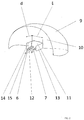
- the Fig. 2 a perspective view of a wheel arch
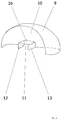
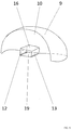
- the Fig. 3 to 6 a perspective view of a wheel well in alternative embodiments of the invention.
- the Fig. 1 schematically illustrates the front portion of a motor vehicle with an engine compartment 1 , which comprises a drive unit 2 and where on each side of the engine compartment 1, a wheel well 4 is arranged, in which a driven wheel 5 of the vehicle is connected via a drive shaft 6 to the drive unit 2 and includes a suspension 7 .
- the drive wheel 5 has a brake system 8 .
- the actual wheel housing 4 is formed by a wheel shell 9 and a side wall 10 .
- a cutout 11 is formed through which the wheel suspensions 7 , possibly the drive shaft 6 or further (not shown) mechanical parts of the front axle pass.
- the cutout 11 has the width B.
- a front ear 12 and a rear ear 13 is fixed, both ears 12, 13 have an upper edge 14 and a lower edge 15 .
- Both ears 12, 13 have the length L , with the proviso that the length L of the front ear 12 and the rear ear 13 corresponds to at least 20% of the width B of the cutout 11 .
- Upper edges 14, 14 'of the front ear 12 and the rear ear 13 are connected to a roof 16 .
- lower edges 15 , 15 'of the front ear 12 and the rear ear 13 have horizontal apertures 17 , between which a gap 18 is.
- the lower edges 15, 15 'of the ears 12 , 13 can be connected to a cover 19 , which is designed as a separate part or by a beak-shaped extension 20, which is part of the lower cover 3 of the engine compartment 1 is formed ,
- the impacting air penetrates into the engine compartment 1 , where the static pressure increases.
- compressed air is forced through many openings in the body in the outside environment, such openings are also the cutouts 11 in the wheel arches 4.
- the compressed air flows from the engine compartment 1 through said cutouts 4 and the direction and compactness of the outgoing air flow is greatly intensified by the action of the front ear 12 and the rear ear 13 .
- the air flow will not pass into chaotic turbulence by this influence, but stabilized in one direction, closer to the wheels 5 and led to the brake system mounted there 8 , whereby the cooling effect on the brake system 8 is significantly increased.
- the said cooling effect is further increased by the connection of the front and rear ears 12, 13 with a roof 16 , which on the one hand increases the rigidity of the wheel house 4 and on the other hand improves the directional stability of the cooling air flow, increases the homogeneity of this flow, resulting in an increase the average flow velocity and thereby also in a further increase in the cooling effect.
- This can also be achieved by closing the space between the front ear 12 and the rear ear 13 by means of horizontal apertures 17 attached to these ears.
- the gap 18 between the horizontal aperture 17 allows easy placement of the wheel housing 4 on the motor vehicle.
- the space between the front ear 12 and the rear ear 13 in the lower region may be closed by a separate cover 19 , which may be, for example, a plastic part secured to the ears 12, 13 in the usual manner.
- the cover 19 can be replaced by a beak-shaped extension 20 , which is part of the lower cover 3 of the engine compartment 1 .
- the use of the wheel arch 4 according to the invention brings a number of advantages, among the most significant is the significant reduction of the heat load on the front brake system 4, eg in the case of continuous braking when driving at a lower speed. Furthermore, it is the reduction of contamination of the front brake system 4 by water and dirt particles, since instead of the polluted outside air to the brakes, the pre-cleaned air from the engine compartment 1 is supplied. Another clear advantage is the ability to reduce the dimensions of the impacting outside air supplying cooling ducts or these can be completely eliminated and so reduce the air resistance of the vehicle, resulting in a reduction in fuel consumption and pollutant content in exhaust gases.
Abstract
Description
- Die Erfindung betrifft einen Radkasten des Kraftfahrzeuges, insbesondere einen Radkasten mit einer Friktionsbremse.
- Die Anforderungen auf passive Sicherheit bei Kraftfahrzeugen werden derzeit generell gesteigert, wobei ein der bedeutenden Elemente der passiven Sicherheit die gute und dauerhafte Bremswirkung ist. Diese wird durch die Verwendung von Bremsanlagen verschiedener Ausführung erzielt, wobei zu den Hauptmerkmalen der Bremsanlagen in meisten Fällen die Bremsscheibe gehört. Die Bremswirkung wird meistens durch das beiderseitige axiale Anpressen der Bremsbeläge erzielt. Infolge der starken Reibung zwischen den Bremsbelägen und der Bremsscheibe, z.B. beim intensiven Bremsvorgang bei der Fahrt bergabwärts, entsteht Wärmeenergie, die von der Masse der Bremsanlage aufgenommen wird. Falls die Temperatur eines der Teile der Bremsanlage die erlaubten Grenzwerte übersteigt, kann dies zur abrupten Reduzierung der Bremswirkung eventuell zum Aussetzen der Bremswirkung führen und nachfolgend sowohl die Fahrzeuginsassen, wie auch die Außenumgebung gefährden.
- Damit solche oben genannte Probleme nicht vorkommen, muss eine Kühlung der Bremsanlage gewährleistet werden. Die primäre Kühlmaßnahme hängt mit der Anordnung in der Radfelge zusammen, wo durch natürliche Strömung infolge der Fahrzeugbewegung sowie der Rotation des Rades eine Kühlwirkung erreicht wird. Diese ist jedoch bei modernen Fahrzeugen mit hohem Gewicht, hoher Durchschnittsgeschwindigkeit und mit Maßnahmen zur Senkung des Luftwiderstandes des Fahrzeuges unzureichend.
- Zur Verbesserung der Kühlwirkung ist die Verwendung eines Systems zur Nachkühlung durch Luftströmung bekannt, wo die Kühlluft aus der Außenumgebung durch Kanäle oder Halbkanäle aufgenommen und zur Bremsanlage gerichtet wird. Die angeführte Anordnung ist z.B. aus der Patentanmeldung
DE 102012209980 A1 ersichtlich, wo die Kühlluft hinter dem Kühlergrill gesammelt und über ein Kanal zu der Bremsanlage geleitet wird. Die PatentschriftEP 0757642 B1 beschreibt eine Lösung, wo in dem Radkasten eventuell in seiner seitlichen Außenabdeckung Öffnungen mit Führungslamellen ausgebildet sind, um die Luftströmung zur Bremsanlage zu leiten. - Die genannten Maßnahmen, basierend auf einer zusätzlichen Verstärkung der Außenluftzufuhr zur Bremsanlage, haben neben positiver Kühlwirkung auch einige Nachteile. Der erste Nachteil liegt in der Erhöhung des frontalen Luftwiderstandes des Fahrzeuges durch die Kühlluftzufuhr zur Bremsanlage, da die kühle Luft von der Einlassrichtung, die der Fahrtrichtung entspricht, in eine etwa rechtwinklig zur Fahrzeugachse liegende Richtung abgelenkt werden muss, wodurch das Fahrzeug einer Kräfteeinwirkung ausgesetzt wird, die den Luftwiderstandskoeffizient des Fahrzeuges verschlechtert, was sich in erhöhtem Kraftstoffverbrauch, reduzierter Höchstgeschwindigkeit und erhöhtem Schadstoffgehalt in Abgasen auswirkt. Den weiteren Nachteil stellt die erhöhte Verschmutzung der Funktionsstellen an Abschnitten der Bremsscheibe durch das Eintragen von Wasser und weiterer Schmutzpartikeln dar, die insbesondere beim Regen oder nach dem Regen in der Luft vor dem Fahrzeug stark enthalten sind.
- Die Aufgabe wird durch einen erfindungsgemäßen Radkasten eines Kraftfahrzeuges gelöst, das an beiden Seiten des Motorraumes mit unterer Motorabdeckung angeordnet ist, wobei der Radkasten aus einer Radschale und einer Seitenwand besteht, in der ein Ausschnitt ausgebildet ist, der den Motorraum mit dem Radkasten verbindet. Die Darstellung der Erfindung liegt darin, dass an dem Ausschnitt mit der Breite B ein abragendes vorderes Ohr sowie ein hinteres Ohr mit der Länge L angeordnet sind, die eine vorteilhafte viereckige Form mit einer Oberkannte und einer Unterkannte aufweisen, wobei das Verhältnis der Länge L zur Breite B ist L≥0,2B. Um die Kühlwirkung zu gewährleisten sind die Oberkanten des vorderen und hinteren Ohres mit einer Überdachung verbunden. Dies kann auch so erzielt werden, dass an der Unterkante des vorderen sowie des hinteren Ohres horizontale Blenden angeordnet sind, zwischen denen ein Spalt ist. Alternativ kann an der Unterkante des vorderen und hinteren Ohres eine abnehmbare Abdeckung oder ein schnabelförmiger Ausläufer angeordnet werden, der Bestandteil der unteren Motorabdeckung ist.
- Die Erfindung wird näher anhand der Ausführungsbeispiele gemäß den beigefügten Zeichnungen erläutert, in denen die
Fig. 1 schematisch eine Anordnung eines Motorraumes darstellt, dieFig. 2 eine perspektivische Ansicht eines Radkastens und dieFig. 3 bis 6 eine perspektivische Ansicht eines Radkastens in alternativen Ausführungen der Erfindung. - Die
Fig. 1 stellt schematisch den vorderen Abschnitt eines Kraftfahrzeuges mit einem Motorraum 1 dar, der eine Antriebseinheit 2 umfasst und wo an jeder Seite des Motorraumes 1 ein Radkasten 4 angeordnet ist, in dem ein getriebenes Rad 5 des Fahrzeuges über eine Antriebswelle 6 an die Antriebseinheit 2 angeschlossen ist und eine Radaufhängung 7 umfasst. Das Antriebsrad 5 weist eine Bremsanlage 8 auf. - Der eigentliche Radkasten 4 wird gebildet durch eine Radschale 9 und eine Seitenwand 10. In der Seitenwand 10 ist ein Ausschnitt 11 ausgebildet, durch den die Radaufhängungen 7, eventuell die Antriebswelle 6 oder weitere (nicht dargestellte) mechanische Teile der Vorderachse durchgehen. Der Ausschnitt 11 hat die Breite B. Zum Ausschnitt 11 ist ein vorderes Ohr 12 und ein hinteres Ohr 13 befestigt, wobei beide Ohren 12, 13 eine Oberkante 14 und eine Unterkante 15 aufweisen. Beide Ohren 12, 13 haben die Länge L, wobei gilt, dass die Länge L des vorderen Ohres 12 und des hinteren Ohres 13 wenigstens 20% der Breite B des Ausschnitts 11 entspricht. Oberkanten 14, 14' des vorderen Ohres 12 und des hinteren Ohres 13 sind mit einer Überdachung 16 verbunden. In einer alternativen Ausführung weisen Unterkanten 15, 15' des vorderen Ohres 12 und des hinteren Ohres 13 horizontale Blenden 17 auf, zwischen denen ein Spalt 18 ist. In einer weiteren alternativen Ausführung können die Unterkanten 15, 15' der Ohren 12, 13 mit einer Abdeckung 19 verbunden werden, die als separates Teil ausgeführt ist oder durch einen schnabelförmigen Ausläufer 20, der Bestandteil der unteren Abdeckung 3 des Motorraumes 1 ist, gebildet wird.
- Während der Fahrt des Kraftfahrzeuges dringt die anprallende Luft in den Motorraum 1 hinein, wo sich der statische Druck erhöht. So komprimierte Luft wird durch viele Öffnungen in der Karosserie in die Außenumgebung hinausgedrängt, solche Öffnungen stellen auch die Ausschnitte 11 in den Radkästen 4 dar. Die komprimierte Luft strömt aus dem Motorraum 1 durch die genannten Ausschnitte 4 und die Richtung sowie die Kompaktheit der ausgehenden Luftströmung wird durch die Einwirkung des vorderen Ohres 12 und des hinteren Ohres 13 stark intensiviert. Der Luftstrom wird durch diesen Einfluss nicht in chaotische Turbulenzen übergehen, sondern in einer Richtung stabilisiert, näher an die Räder 5 und zu der dort gelagerten Bremsanlage 8 geführt, wodurch die Kühlwirkung auf die Bremsanlage 8 deutlich erhöht wird. Die genannte Kühlwirkung wird weiter durch die Verbindung des vorderen und des hinteren Ohres 12, 13 mit einer Überdachung 16 gesteigert, was einerseits die Steifigkeit des Radkastens 4 erhöht und anderseits die Richtungsstabilität der Kühlluftströmung verbessert, die Homogenität dieser Strömung erhöht, was sich in einer Erhöhung der mittleren Strömungsgeschwindigkeit und dadurch auch in weiterer Steigerung der Kühlwirkung auswirkt. Dies kann auch durch die Schließung des Raumes zwischen dem vorderen Ohr 12 und dem hinteren Ohr 13 mittels horizontaler Blenden 17 erzielt werden, die zu diesen Ohren befestigt sind. Der Spalt 18 zwischen den horizontalen Blenden 17 ermöglicht ein einfaches Aufsetzen des Radkastens 4 am Kraftfahrzeug. Alternativ kann der Raum zwischen dem vorderen Ohr 12 und dem hinteren Ohr 13 im unteren Bereich durch eine separate Abdeckung 19 geschlossen werden, was z.B. ein zu den Ohren 12, 13 auf üblich bekannte Weise befestigtes Kunststoffteil sein kann. Für die Vereinfachung kann die Abdeckung 19 durch einen schnabelförmigen Ausläufer 20 ersetzt werden, der Bestandteil der unteren Abdeckung 3 des Motorraumes 1 ist.
- Der Gebrauch des erfindungsgemäßen Radkastens 4 bringt eine Reihe von Vorteilen, zu den bedeutendsten gehört die deutliche Reduzierung der Wärmebelastung der vorderen Bremsanlage 4, z.B. beim andauernden Bremsen bei einer Fahrt mit geringerer Geschwindigkeit. Ferner ist es die Reduzierung der Verschmutzung der vorderen Bremsanlage 4 durch Wasser und Schmutzpartikel, da statt der verschmutzten Außenluft zu den Bremsen die vorgereinigte Luft aus dem Motorraum 1 zugeführt wird. Weiterer deutlicher Vorteil besteht in der Möglichkeit, die Abmessungen der die anprallende Außenluft zuführenden Kühlkanäle zu reduzieren oder diese völlig entfallen lassen und so den Luftwiderstand des Fahrzeuges reduzieren, was sich in einer Reduzierung des Kraftstoffverbrauches und des Schadstoffgehaltes in Abgasen auswirkt.
-
- 1.
- Motorraum
- 2.
- Antriebseinheit
- 3.
- Untere Motorabdeckung
- 4.
- Radkasten
- 5.
- Antriebsrad
- 6.
- Antriebswelle
- 7.
- Radaufhängung
- 8.
- Bremsanlage
- 9.
- Radschale
- 10.
- Seitenwand
- 11.
- Ausschnitt
- 12.
- vorderes Ohr
- 13.
- hinteres Ohr
- 14.
- Oberkante
- 15.
- Unterkante
- 16.
- Überdachung
- 17.
- horizontale Blende
- 18.
- Spalt
- 19.
- Deckel
- 20.
- Schnabel
- B
- Breite
- L
- Länge
Claims (5)
- Radkasten (4) eines Kraftfahrzeuges, der an beiden Seiten eines Motorraumes (1) mit unterer Abdeckung (3) des Motorraumes (1) angeordnet ist, wobei der Radkasten (4) aus einer Radschale (9) und einer Seitenwand (10) besteht und in der Seitenwand (10) ein Ausschnitt (11) ausgebildet ist, der den Motorraum (1) mit dem Radkasten (4) verbindet, dadurch gekennzeichnet, dass an dem Ausschnitt (11) mit der Breite (B) ein abragendes vorderes Ohr (12) sowie ein hinteres Ohr (13) mit der Länge (L) angeordnet sind, die eine vorteilhafte viereckige Form mit einer Oberkannte (14) und einer Unterkannte (15) aufweisen, wobei das Verhältnis der Länge (L) zur Breite (B) ist L≥0,2B.
- Radkasten (4) eines Kraftfahrzeuges nach Anspruch 1 dadurch gekennzeichnet, dass die Oberkannte (14, 14') des vorderen Ohres (12) und des hinteren Ohres (13) mit einer Überdachung (16) verbunden sind.
- Radkasten (4) eines Kraftfahrzeuges nach Anspruch 1 dadurch gekennzeichnet, dass an den Unterkannten (15, 15') des vorderen Ohres (12) und des hinteren Ohres (13) horizontale Blenden (17) mit einem Spalt (18) dazwischen angeordnet sind.
- Radkasten (4) eines Kraftfahrzeuges nach Anspruch 1 dadurch gekennzeichnet, dass an den Unterkannten (15, 15') des vorderen Ohres (12) und des hinteren Ohres (13) eine abnehmbare Abdeckung (19) angeordnet ist.
- Radkasten (4) eines Kraftfahrzeuges nach Anspruch 1 dadurch gekennzeichnet, dass an den Unterkannten (15, 15') des vorderen Ohres (12) und des hinteren Ohres (13) ein schnabelförmiger Ausläufer (20) angeordnet ist, der Bestandteil der unteren Abdeckung (3) des Motorraumes (1) ist.
Applications Claiming Priority (1)
| Application Number | Priority Date | Filing Date | Title |
|---|---|---|---|
| CZ2014-969A CZ2014969A3 (cs) | 2014-12-30 | 2014-12-30 | Podběh kola motorového vozidla |
Publications (2)
| Publication Number | Publication Date |
|---|---|
| EP3040256A1 true EP3040256A1 (de) | 2016-07-06 |
| EP3040256B1 EP3040256B1 (de) | 2018-02-28 |
Family
ID=55352987
Family Applications (1)
| Application Number | Title | Priority Date | Filing Date |
|---|---|---|---|
| EP15466023.7A Active EP3040256B1 (de) | 2014-12-30 | 2015-12-22 | Radkasten eines kraftfahrzeuges |
Country Status (2)
| Country | Link |
|---|---|
| EP (1) | EP3040256B1 (de) |
| CZ (1) | CZ2014969A3 (de) |
Cited By (1)
| Publication number | Priority date | Publication date | Assignee | Title |
|---|---|---|---|---|
| DE102018122712A1 (de) * | 2018-09-17 | 2020-03-19 | Dr. Ing. H.C. F. Porsche Aktiengesellschaft | Radhausschalengitter |
Citations (7)
| Publication number | Priority date | Publication date | Assignee | Title |
|---|---|---|---|---|
| EP0757642B1 (de) | 1995-01-18 | 1999-06-16 | Air Fenders Ltd. | Kotflügel zur kühlung von reifen und bremsen und zur wasserspritzkontrolle |
| DE10159783A1 (de) * | 2001-12-05 | 2003-06-18 | Porsche Ag | Kühlluftführung für ein Kraftfahrzeug |
| DE102008052938A1 (de) * | 2008-10-23 | 2009-05-20 | Daimler Ag | Innenverkleidung für ein Radhaus eines Kraftfahrzeugs |
| DE102008039728A1 (de) * | 2008-08-26 | 2010-03-04 | Bayerische Motoren Werke Aktiengesellschaft | Luftführungseinrichtung |
| DE102011007126A1 (de) * | 2011-04-11 | 2012-10-11 | Bayerische Motoren Werke Aktiengesellschaft | Kraftfahrzeug mit einem Radhaus |
| DE102012209980A1 (de) | 2011-06-20 | 2012-12-20 | GM Global Technology Operations LLC (n.d. Ges. d. Staates Delaware) | Kombiniertes Kondensationskühler-Lüftermodul und Bremskühlkanal-Verschlusssystem |
| GB2510163A (en) * | 2013-01-28 | 2014-07-30 | Nissan Motor Mfg Uk Ltd | A vehicle wheel arch liner |
-
2014
- 2014-12-30 CZ CZ2014-969A patent/CZ2014969A3/cs unknown
-
2015
- 2015-12-22 EP EP15466023.7A patent/EP3040256B1/de active Active
Patent Citations (7)
| Publication number | Priority date | Publication date | Assignee | Title |
|---|---|---|---|---|
| EP0757642B1 (de) | 1995-01-18 | 1999-06-16 | Air Fenders Ltd. | Kotflügel zur kühlung von reifen und bremsen und zur wasserspritzkontrolle |
| DE10159783A1 (de) * | 2001-12-05 | 2003-06-18 | Porsche Ag | Kühlluftführung für ein Kraftfahrzeug |
| DE102008039728A1 (de) * | 2008-08-26 | 2010-03-04 | Bayerische Motoren Werke Aktiengesellschaft | Luftführungseinrichtung |
| DE102008052938A1 (de) * | 2008-10-23 | 2009-05-20 | Daimler Ag | Innenverkleidung für ein Radhaus eines Kraftfahrzeugs |
| DE102011007126A1 (de) * | 2011-04-11 | 2012-10-11 | Bayerische Motoren Werke Aktiengesellschaft | Kraftfahrzeug mit einem Radhaus |
| DE102012209980A1 (de) | 2011-06-20 | 2012-12-20 | GM Global Technology Operations LLC (n.d. Ges. d. Staates Delaware) | Kombiniertes Kondensationskühler-Lüftermodul und Bremskühlkanal-Verschlusssystem |
| GB2510163A (en) * | 2013-01-28 | 2014-07-30 | Nissan Motor Mfg Uk Ltd | A vehicle wheel arch liner |
Cited By (1)
| Publication number | Priority date | Publication date | Assignee | Title |
|---|---|---|---|---|
| DE102018122712A1 (de) * | 2018-09-17 | 2020-03-19 | Dr. Ing. H.C. F. Porsche Aktiengesellschaft | Radhausschalengitter |
Also Published As
| Publication number | Publication date |
|---|---|
| CZ2014969A3 (cs) | 2016-07-07 |
| EP3040256B1 (de) | 2018-02-28 |
Similar Documents
| Publication | Publication Date | Title |
|---|---|---|
| DE102010037615B4 (de) | Luftleiteinrichtung zur Kühlerabluftführung für eine Kühlereinheit | |
| DE102010037617A1 (de) | Luftleiteinrichtung | |
| DE102008039728A1 (de) | Luftführungseinrichtung | |
| EP1753943A1 (de) | Kühlsystem | |
| DE102010037614B4 (de) | Luftleiteinrichtung | |
| EP2644419A1 (de) | Gehäuse zur Aufnahme und Temperaturregulierung einer elektronischen Einrichtung und Fahrzeug mit diesem Gehäuse | |
| DE102017129199A1 (de) | Luftstrommanagementsystem für ein fahrzeug | |
| DE102017005904A1 (de) | Kraftfahrzeug mit einer Kofferraumvorrichtung, Kofferraumvorrichtung für ein Kraftfahrzeug und Verfahren zur Luftströmungseinstellung bei einem Kraftfahrzeug | |
| DE102020006425A1 (de) | Vorrichtung zur Kühlung mindestens einer Radbremse eines Fahrzeugs | |
| DE102014205603A1 (de) | Luftleitvorrichtung für ein Fahrzeug | |
| EP3040256B1 (de) | Radkasten eines kraftfahrzeuges | |
| DE102019207567A1 (de) | Luftausströmer für den Innenraum eines Kraftfahrzeugs | |
| DE2747785C2 (de) | Vorrichtung zur Kühlung der Brennkraftmaschine eines Kraftfahrzeuges | |
| DE102016115514B4 (de) | Aerodynamikbauteil für die Montage an einem Frontabschnitt eines Fahrzeugs | |
| DE102006026098A1 (de) | Kraftfahrzeug | |
| DE102016215032A1 (de) | Luftleiteinrichtung für ein Kraftfahrzeug | |
| DE102013010637A1 (de) | Belüftungseinrichtung für eine Scheibe eines Kraftwagens | |
| DE102014119023A1 (de) | Luftleiteinrichtung für eine Radhausentlüftung | |
| EP2848478A2 (de) | Flussumschalter | |
| DE102013219706A1 (de) | Anordnung zum zeitweiligen Erhöhen eines Luftwiderstands eines Schienenfahrzeugs | |
| DE102017001125B4 (de) | Kraftfahrzeug mit einem Querträger und mit einem Belüftungselement | |
| DE102009036758A1 (de) | Luftleiteinrichtung für einen Kraftwagen | |
| DE102016009064B4 (de) | Fahrzeug | |
| DE102019003358A1 (de) | Aktiver Radspoiler für ein Fahrzeug | |
| DE102013203445A1 (de) | Luftleitvorrichtung für ein Fahrzeug sowie Fahrzeug mit einer solchen Luftleitvorrichtung |
Legal Events
| Date | Code | Title | Description |
|---|---|---|---|
| PUAI | Public reference made under article 153(3) epc to a published international application that has entered the european phase |
Free format text: ORIGINAL CODE: 0009012 |
|
| AK | Designated contracting states |
Kind code of ref document: A1 Designated state(s): AL AT BE BG CH CY CZ DE DK EE ES FI FR GB GR HR HU IE IS IT LI LT LU LV MC MK MT NL NO PL PT RO RS SE SI SK SM TR |
|
| AX | Request for extension of the european patent |
Extension state: BA ME |
|
| 17P | Request for examination filed |
Effective date: 20170109 |
|
| RBV | Designated contracting states (corrected) |
Designated state(s): AL AT BE BG CH CY CZ DE DK EE ES FI FR GB GR HR HU IE IS IT LI LT LU LV MC MK MT NL NO PL PT RO RS SE SI SK SM TR |
|
| RIC1 | Information provided on ipc code assigned before grant |
Ipc: B60T 5/00 20060101ALI20170621BHEP Ipc: B62D 25/18 20060101AFI20170621BHEP Ipc: F16D 65/847 20060101ALI20170621BHEP |
|
| GRAP | Despatch of communication of intention to grant a patent |
Free format text: ORIGINAL CODE: EPIDOSNIGR1 |
|
| INTG | Intention to grant announced |
Effective date: 20170808 |
|
| GRAS | Grant fee paid |
Free format text: ORIGINAL CODE: EPIDOSNIGR3 |
|
| GRAA | (expected) grant |
Free format text: ORIGINAL CODE: 0009210 |
|
| AK | Designated contracting states |
Kind code of ref document: B1 Designated state(s): AL AT BE BG CH CY CZ DE DK EE ES FI FR GB GR HR HU IE IS IT LI LT LU LV MC MK MT NL NO PL PT RO RS SE SI SK SM TR |
|
| REG | Reference to a national code |
Ref country code: GB Ref legal event code: FG4D Free format text: NOT ENGLISH Ref country code: CH Ref legal event code: EP |
|
| REG | Reference to a national code |
Ref country code: AT Ref legal event code: REF Ref document number: 973785 Country of ref document: AT Kind code of ref document: T Effective date: 20180315 |
|
| REG | Reference to a national code |
Ref country code: IE Ref legal event code: FG4D Free format text: LANGUAGE OF EP DOCUMENT: GERMAN |
|
| REG | Reference to a national code |
Ref country code: DE Ref legal event code: R096 Ref document number: 502015003200 Country of ref document: DE |
|
| REG | Reference to a national code |
Ref country code: NL Ref legal event code: MP Effective date: 20180228 |
|
| REG | Reference to a national code |
Ref country code: LT Ref legal event code: MG4D |
|
| PG25 | Lapsed in a contracting state [announced via postgrant information from national office to epo] |
Ref country code: NL Free format text: LAPSE BECAUSE OF FAILURE TO SUBMIT A TRANSLATION OF THE DESCRIPTION OR TO PAY THE FEE WITHIN THE PRESCRIBED TIME-LIMIT Effective date: 20180228 Ref country code: HR Free format text: LAPSE BECAUSE OF FAILURE TO SUBMIT A TRANSLATION OF THE DESCRIPTION OR TO PAY THE FEE WITHIN THE PRESCRIBED TIME-LIMIT Effective date: 20180228 Ref country code: LT Free format text: LAPSE BECAUSE OF FAILURE TO SUBMIT A TRANSLATION OF THE DESCRIPTION OR TO PAY THE FEE WITHIN THE PRESCRIBED TIME-LIMIT Effective date: 20180228 Ref country code: CY Free format text: LAPSE BECAUSE OF FAILURE TO SUBMIT A TRANSLATION OF THE DESCRIPTION OR TO PAY THE FEE WITHIN THE PRESCRIBED TIME-LIMIT Effective date: 20180228 Ref country code: FI Free format text: LAPSE BECAUSE OF FAILURE TO SUBMIT A TRANSLATION OF THE DESCRIPTION OR TO PAY THE FEE WITHIN THE PRESCRIBED TIME-LIMIT Effective date: 20180228 Ref country code: NO Free format text: LAPSE BECAUSE OF FAILURE TO SUBMIT A TRANSLATION OF THE DESCRIPTION OR TO PAY THE FEE WITHIN THE PRESCRIBED TIME-LIMIT Effective date: 20180528 Ref country code: ES Free format text: LAPSE BECAUSE OF FAILURE TO SUBMIT A TRANSLATION OF THE DESCRIPTION OR TO PAY THE FEE WITHIN THE PRESCRIBED TIME-LIMIT Effective date: 20180228 |
|
| PG25 | Lapsed in a contracting state [announced via postgrant information from national office to epo] |
Ref country code: LV Free format text: LAPSE BECAUSE OF FAILURE TO SUBMIT A TRANSLATION OF THE DESCRIPTION OR TO PAY THE FEE WITHIN THE PRESCRIBED TIME-LIMIT Effective date: 20180228 Ref country code: SE Free format text: LAPSE BECAUSE OF FAILURE TO SUBMIT A TRANSLATION OF THE DESCRIPTION OR TO PAY THE FEE WITHIN THE PRESCRIBED TIME-LIMIT Effective date: 20180228 Ref country code: RS Free format text: LAPSE BECAUSE OF FAILURE TO SUBMIT A TRANSLATION OF THE DESCRIPTION OR TO PAY THE FEE WITHIN THE PRESCRIBED TIME-LIMIT Effective date: 20180228 Ref country code: BG Free format text: LAPSE BECAUSE OF FAILURE TO SUBMIT A TRANSLATION OF THE DESCRIPTION OR TO PAY THE FEE WITHIN THE PRESCRIBED TIME-LIMIT Effective date: 20180528 Ref country code: GR Free format text: LAPSE BECAUSE OF FAILURE TO SUBMIT A TRANSLATION OF THE DESCRIPTION OR TO PAY THE FEE WITHIN THE PRESCRIBED TIME-LIMIT Effective date: 20180529 |
|
| PG25 | Lapsed in a contracting state [announced via postgrant information from national office to epo] |
Ref country code: MT Free format text: LAPSE BECAUSE OF FAILURE TO SUBMIT A TRANSLATION OF THE DESCRIPTION OR TO PAY THE FEE WITHIN THE PRESCRIBED TIME-LIMIT Effective date: 20180228 |
|
| PG25 | Lapsed in a contracting state [announced via postgrant information from national office to epo] |
Ref country code: RO Free format text: LAPSE BECAUSE OF FAILURE TO SUBMIT A TRANSLATION OF THE DESCRIPTION OR TO PAY THE FEE WITHIN THE PRESCRIBED TIME-LIMIT Effective date: 20180228 Ref country code: IT Free format text: LAPSE BECAUSE OF FAILURE TO SUBMIT A TRANSLATION OF THE DESCRIPTION OR TO PAY THE FEE WITHIN THE PRESCRIBED TIME-LIMIT Effective date: 20180228 Ref country code: EE Free format text: LAPSE BECAUSE OF FAILURE TO SUBMIT A TRANSLATION OF THE DESCRIPTION OR TO PAY THE FEE WITHIN THE PRESCRIBED TIME-LIMIT Effective date: 20180228 Ref country code: PL Free format text: LAPSE BECAUSE OF FAILURE TO SUBMIT A TRANSLATION OF THE DESCRIPTION OR TO PAY THE FEE WITHIN THE PRESCRIBED TIME-LIMIT Effective date: 20180228 Ref country code: AL Free format text: LAPSE BECAUSE OF FAILURE TO SUBMIT A TRANSLATION OF THE DESCRIPTION OR TO PAY THE FEE WITHIN THE PRESCRIBED TIME-LIMIT Effective date: 20180228 |
|
| REG | Reference to a national code |
Ref country code: DE Ref legal event code: R097 Ref document number: 502015003200 Country of ref document: DE |
|
| PG25 | Lapsed in a contracting state [announced via postgrant information from national office to epo] |
Ref country code: SM Free format text: LAPSE BECAUSE OF FAILURE TO SUBMIT A TRANSLATION OF THE DESCRIPTION OR TO PAY THE FEE WITHIN THE PRESCRIBED TIME-LIMIT Effective date: 20180228 Ref country code: DK Free format text: LAPSE BECAUSE OF FAILURE TO SUBMIT A TRANSLATION OF THE DESCRIPTION OR TO PAY THE FEE WITHIN THE PRESCRIBED TIME-LIMIT Effective date: 20180228 Ref country code: SK Free format text: LAPSE BECAUSE OF FAILURE TO SUBMIT A TRANSLATION OF THE DESCRIPTION OR TO PAY THE FEE WITHIN THE PRESCRIBED TIME-LIMIT Effective date: 20180228 |
|
| PLBE | No opposition filed within time limit |
Free format text: ORIGINAL CODE: 0009261 |
|
| STAA | Information on the status of an ep patent application or granted ep patent |
Free format text: STATUS: NO OPPOSITION FILED WITHIN TIME LIMIT |
|
| 26N | No opposition filed |
Effective date: 20181129 |
|
| PG25 | Lapsed in a contracting state [announced via postgrant information from national office to epo] |
Ref country code: SI Free format text: LAPSE BECAUSE OF FAILURE TO SUBMIT A TRANSLATION OF THE DESCRIPTION OR TO PAY THE FEE WITHIN THE PRESCRIBED TIME-LIMIT Effective date: 20180228 |
|
| REG | Reference to a national code |
Ref country code: CH Ref legal event code: PL |
|
| PG25 | Lapsed in a contracting state [announced via postgrant information from national office to epo] |
Ref country code: LU Free format text: LAPSE BECAUSE OF NON-PAYMENT OF DUE FEES Effective date: 20181222 Ref country code: MC Free format text: LAPSE BECAUSE OF FAILURE TO SUBMIT A TRANSLATION OF THE DESCRIPTION OR TO PAY THE FEE WITHIN THE PRESCRIBED TIME-LIMIT Effective date: 20180228 |
|
| REG | Reference to a national code |
Ref country code: IE Ref legal event code: MM4A |
|
| REG | Reference to a national code |
Ref country code: BE Ref legal event code: MM Effective date: 20181231 |
|
| PG25 | Lapsed in a contracting state [announced via postgrant information from national office to epo] |
Ref country code: IE Free format text: LAPSE BECAUSE OF NON-PAYMENT OF DUE FEES Effective date: 20181222 |
|
| PG25 | Lapsed in a contracting state [announced via postgrant information from national office to epo] |
Ref country code: BE Free format text: LAPSE BECAUSE OF NON-PAYMENT OF DUE FEES Effective date: 20181231 |
|
| PG25 | Lapsed in a contracting state [announced via postgrant information from national office to epo] |
Ref country code: LI Free format text: LAPSE BECAUSE OF NON-PAYMENT OF DUE FEES Effective date: 20181231 Ref country code: CH Free format text: LAPSE BECAUSE OF NON-PAYMENT OF DUE FEES Effective date: 20181231 |
|
| PG25 | Lapsed in a contracting state [announced via postgrant information from national office to epo] |
Ref country code: TR Free format text: LAPSE BECAUSE OF FAILURE TO SUBMIT A TRANSLATION OF THE DESCRIPTION OR TO PAY THE FEE WITHIN THE PRESCRIBED TIME-LIMIT Effective date: 20180228 |
|
| PG25 | Lapsed in a contracting state [announced via postgrant information from national office to epo] |
Ref country code: PT Free format text: LAPSE BECAUSE OF FAILURE TO SUBMIT A TRANSLATION OF THE DESCRIPTION OR TO PAY THE FEE WITHIN THE PRESCRIBED TIME-LIMIT Effective date: 20180228 |
|
| PG25 | Lapsed in a contracting state [announced via postgrant information from national office to epo] |
Ref country code: MK Free format text: LAPSE BECAUSE OF NON-PAYMENT OF DUE FEES Effective date: 20180228 Ref country code: HU Free format text: LAPSE BECAUSE OF FAILURE TO SUBMIT A TRANSLATION OF THE DESCRIPTION OR TO PAY THE FEE WITHIN THE PRESCRIBED TIME-LIMIT; INVALID AB INITIO Effective date: 20151222 |
|
| PG25 | Lapsed in a contracting state [announced via postgrant information from national office to epo] |
Ref country code: IS Free format text: LAPSE BECAUSE OF FAILURE TO SUBMIT A TRANSLATION OF THE DESCRIPTION OR TO PAY THE FEE WITHIN THE PRESCRIBED TIME-LIMIT Effective date: 20180628 |
|
| REG | Reference to a national code |
Ref country code: AT Ref legal event code: MM01 Ref document number: 973785 Country of ref document: AT Kind code of ref document: T Effective date: 20201222 |
|
| PG25 | Lapsed in a contracting state [announced via postgrant information from national office to epo] |
Ref country code: AT Free format text: LAPSE BECAUSE OF NON-PAYMENT OF DUE FEES Effective date: 20201222 |
|
| PGFP | Annual fee paid to national office [announced via postgrant information from national office to epo] |
Ref country code: CZ Payment date: 20230306 Year of fee payment: 9 |
|
| P01 | Opt-out of the competence of the unified patent court (upc) registered |
Effective date: 20230608 |
|
| PGFP | Annual fee paid to national office [announced via postgrant information from national office to epo] |
Ref country code: FR Payment date: 20230829 Year of fee payment: 9 |
|
| PGFP | Annual fee paid to national office [announced via postgrant information from national office to epo] |
Ref country code: GB Payment date: 20231024 Year of fee payment: 9 |
|
| PGFP | Annual fee paid to national office [announced via postgrant information from national office to epo] |
Ref country code: DE Payment date: 20230828 Year of fee payment: 9 |