EP3039313B1 - Einzelrohrdämpferanordnung - Google Patents
Einzelrohrdämpferanordnung Download PDFInfo
- Publication number
- EP3039313B1 EP3039313B1 EP14840465.0A EP14840465A EP3039313B1 EP 3039313 B1 EP3039313 B1 EP 3039313B1 EP 14840465 A EP14840465 A EP 14840465A EP 3039313 B1 EP3039313 B1 EP 3039313B1
- Authority
- EP
- European Patent Office
- Prior art keywords
- gas
- chamber
- damper
- center axis
- cup
- Prior art date
- Legal status (The legal status is an assumption and is not a legal conclusion. Google has not performed a legal analysis and makes no representation as to the accuracy of the status listed.)
- Active
Links
Images

Classifications
-
- F—MECHANICAL ENGINEERING; LIGHTING; HEATING; WEAPONS; BLASTING
- F16—ENGINEERING ELEMENTS AND UNITS; GENERAL MEASURES FOR PRODUCING AND MAINTAINING EFFECTIVE FUNCTIONING OF MACHINES OR INSTALLATIONS; THERMAL INSULATION IN GENERAL
- F16F—SPRINGS; SHOCK-ABSORBERS; MEANS FOR DAMPING VIBRATION
- F16F9/00—Springs, vibration-dampers, shock-absorbers, or similarly-constructed movement-dampers using a fluid or the equivalent as damping medium
- F16F9/06—Springs, vibration-dampers, shock-absorbers, or similarly-constructed movement-dampers using a fluid or the equivalent as damping medium using both gas and liquid
- F16F9/061—Mono-tubular units
-
- F—MECHANICAL ENGINEERING; LIGHTING; HEATING; WEAPONS; BLASTING
- F16—ENGINEERING ELEMENTS AND UNITS; GENERAL MEASURES FOR PRODUCING AND MAINTAINING EFFECTIVE FUNCTIONING OF MACHINES OR INSTALLATIONS; THERMAL INSULATION IN GENERAL
- F16F—SPRINGS; SHOCK-ABSORBERS; MEANS FOR DAMPING VIBRATION
- F16F9/00—Springs, vibration-dampers, shock-absorbers, or similarly-constructed movement-dampers using a fluid or the equivalent as damping medium
- F16F9/06—Springs, vibration-dampers, shock-absorbers, or similarly-constructed movement-dampers using a fluid or the equivalent as damping medium using both gas and liquid
- F16F9/064—Units characterised by the location or shape of the expansion chamber
- F16F9/065—Expansion chamber provided on the upper or lower end of a damper, separately there from or laterally on the damper
-
- F—MECHANICAL ENGINEERING; LIGHTING; HEATING; WEAPONS; BLASTING
- F16—ENGINEERING ELEMENTS AND UNITS; GENERAL MEASURES FOR PRODUCING AND MAINTAINING EFFECTIVE FUNCTIONING OF MACHINES OR INSTALLATIONS; THERMAL INSULATION IN GENERAL
- F16F—SPRINGS; SHOCK-ABSORBERS; MEANS FOR DAMPING VIBRATION
- F16F9/00—Springs, vibration-dampers, shock-absorbers, or similarly-constructed movement-dampers using a fluid or the equivalent as damping medium
- F16F9/06—Springs, vibration-dampers, shock-absorbers, or similarly-constructed movement-dampers using a fluid or the equivalent as damping medium using both gas and liquid
- F16F9/066—Units characterised by the partition, baffle or like element
- F16F9/067—Partitions of the piston type, e.g. sliding pistons
-
- F—MECHANICAL ENGINEERING; LIGHTING; HEATING; WEAPONS; BLASTING
- F16—ENGINEERING ELEMENTS AND UNITS; GENERAL MEASURES FOR PRODUCING AND MAINTAINING EFFECTIVE FUNCTIONING OF MACHINES OR INSTALLATIONS; THERMAL INSULATION IN GENERAL
- F16F—SPRINGS; SHOCK-ABSORBERS; MEANS FOR DAMPING VIBRATION
- F16F9/00—Springs, vibration-dampers, shock-absorbers, or similarly-constructed movement-dampers using a fluid or the equivalent as damping medium
- F16F9/06—Springs, vibration-dampers, shock-absorbers, or similarly-constructed movement-dampers using a fluid or the equivalent as damping medium using both gas and liquid
- F16F9/068—Springs, vibration-dampers, shock-absorbers, or similarly-constructed movement-dampers using a fluid or the equivalent as damping medium using both gas and liquid where the throttling of a gas flow provides damping action
Definitions
- the present invention relates to a monotube damper assembly for use in a vehicle.
- Monotube damper assemblies are well known in the prior art.
- the U.S. Patent 8,240,642 to Hamberg et al. discloses a monotube damper assembly including a housing defining a main chamber extending along a center axis between a rod end and a closed end.
- a gas cup is disposed in the main chamber and is slidable along the center axis to divide the main chamber into a gas chamber extending between the closed end and the gas cup for containing a high pressured gas and a fluid chamber extending between the gas cup and the rod end.
- a piston is disposed in the fluid chamber and is axially slidable along the center axis.
- a piston rod is connected to the piston and extends through the rod end.
- the gas cup includes a top portion and a body portion extending from the top portion and about the center axis.
- the present invention provides for such monotube damper assembly for use in a vehicle including a gas damper having a restrictor disposed in the gas chamber dividing the gas chamber into an upper chamber and a lower chamber for providing additional damping force to the gas cup by limiting flow of the high pressured gas between the upper chamber and the lower chamber in response to a sliding movement of the gas cup.
- the present invention improves monotube damper assembly performance by providing an additional damping force to the gas cup of the monotube damper assembly.
- the present invention provides for an additional dynamic pressure to the gas cup at higher velocities which results in the onset of lag happening at the higher velocity. As a result, a maximum damping can be tuned at a desired velocity for the monotube damper assembly.
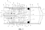
- the assembly 20 includes a housing 22 , as generally indicated, presenting a wall 24 having a tubular shape disposed annularly about a center axis A and extending between a rod end 26 and a closed end 28 to define a main chamber 30 , 32 , 34 .
- An end cap 36 is disposed over the closed end 28 and presents a first mounting ring 38 for attaching the housing 22 to the vehicle.
- a gas cup 40 is disposed in the main chamber 30 , 32 , 34 adjacent to the end cap 36 and is slidable along the center axis A to divide the main chamber 30 , 32 , 34 of the housing 22 into a gas chamber 32 , 34 extending between the closed end 28 and the gas cup 40 for containing a high pressured gas and a fluid chamber 30 extending between the gas cup 40 and the rod end 26 for containing a magneto rheological fluid having a predetermined viscosity.
- the main chamber 30, 32, 34 is separated into the gas chamber 32, 34 and the fluid chamber 30 by the gas cup 40 wherein the gas chamber 32, 34 contains the high pressured gas and extends between the closed end 28 and the gas cup 40 and the fluid chamber 30 contains the magneto rheological fluid and extends between the gas cup 40 and the rod end 26.
- the fluid chamber 30 may contain a damping fluid such as a hydraulic fluid.
- the gas cup 40 includes a top portion 42 having a circular shape and a body portion 44 having a cylindrical shape extending annularly about the center axis A from the top portion 42.
- the top portion 42 of the gas cup 40 presents a pair of protrusions 46 extending axially from the top portion 42 and disposed diametrically from one another across the center axis A .
- the body portion 44 of the gas cup 40 defines a seal groove 48 and a body groove 50 extending annularly about the center axis A and spaced from one another axially along the body portion 44 .
- a gas seal 52 is disposed in the seal groove 48 extending annularly about the body portion 44 of the gas cup 40 and in sealing engagement with the wall 24 of the housing 22 for sealing the gas chamber 32, 34 .
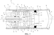
- a piston 54 as generally indicated, having a cylindrical shape is disposed in the fluid chamber 30 of the housing 22 spaced from the gas cup 40 and is axially slidable along the center axis A.
- the piston 54 includes a core unit 56 having a cylindrical shape defining an outer surface 58 extending annularly about the center axis A and a core top 60 presenting a depression 62 having a cylindrical shape extending along the center axis A.
- the core unit 56 also includes a core bottom 64 presenting a cavity 66 having a cylindrical shape extending along the center axis A.
- the outer surface 58 of the core unit 56 presents a plurality of core grooves 68 extending annularly about the center axis A between the core top 60 and the core bottom 64 of the core unit 56 .
- the core unit 56 defines a core unit channel 70 extending along the center axis A and in fluid communication with the depression 62 and the cavity 66 .
- the core bottom 64 of the core unit 56 defines a primary channel 72, 74 having a L-shape in fluid communication between the cavity 66 and the core grooves 68 .
- the primary channel 72, 74 includes a first passage 72 extending radially outwardly from the cavity 66 and perpendicular to the center axis A to establish fluid communication with the outer surface 58 of the core unit 56 .
- the primary channel 72, 74 includes a second passage 74 extending along the outer surface 58 of the core unit 56 parallel to the center axis A to establish fluid communication with the core grooves 68 .
- a stopper 76 is slidably disposed in the cavity 66 and extends along the center axis A for closing the core unit channel 70 .
- a stopper seal 78 is disposed annularly about the stopper 76 and engages the stopper 76 and the core unit 56 for securing the stopper 76 in the cavity 66 of the core unit 56.
- a plurality of coils 80 are disposed in the core groove 68 of the core unit 56 and extends annularly about the core unit 56 and the center axis A for providing a magnetic field to change the predetermined viscosity of the magneto rheological fluid.
- An upper plate 82 having a circular shape is disposed concentrically to the core unit 56 and abuts the core top 60 of the core unit 56 .
- the upper plate 82 presents an upper plate mounting aperture 84 extending through the upper plate 82 and disposed on the center axis A.
- the upper plate 82 presents a plurality of upper plate apertures 86 extending through the upper plate 82 disposed about the upper plate mounting aperture 84.
- a lower plate 88 having a circular shape is disposed concentrically to the core unit 56 and abutting the core bottom 64 of the core unit 56 .
- the lower plate 88 presents a plurality of lower plate apertures 90 extending through the lower plate 88 and disposed about the center axis A.
- a flux ring 92 having a cylindrical shape is disposed about and spaced from the core unit 56 to define a fluid channel 94 extending between the flux ring 92 and the outer surface 58 of the core unit 56 in fluid communication with the upper plate apertures 86 and the lower plate apertures 90 for allowing the magneto rheological fluid to flow through the piston 54.
- the flux ring 92 presents a plurality of flux ring recesses 96 extending annularly about the center axis A and spaced axially from one another in the flux ring 92 for receiving the upper plate 82 of the piston 54 and the lower plate 88 of the piston 54 .
- the piston 54 may include a core unit 56 having a core top 60 and a core bottom 64 defining at least one fluid channel 94 extending from the core top 60 to the core bottom 64 of the core unit 56 .
- a rod guide 98 as generally indicated, having a cylindrical shape is disposed concentrically on the center axis A in the fluid chamber 30 and engages the housing 22 adjacent to the rod end 26 and spaced part from the piston 54.
- the rod guide 98 defines a central bore 100, 102 having a cylindrical shape presenting a groove section 100 and a pit section 102 extending along the center axis A .
- a piston rod seal 104 is disposed in the groove section 100 of the central bore 100,102 extending annularly about the center axis A .
- the rod guide 98 defines a plurality of rod guide grooves 106 extending annularly about the rod guide 98 and the center axis A.
- a rod guide seal 108 extends annularly about the rod guide 98 in each of the rod guide grooves 106 and engaging the wall 24 of the housing 22 for sealing the fluid chamber 30.
- a piston rod 110 extends between a mating end 112 and a mounting end 114 along the center axis A and is connected to the depression 62 of the core unit 56 of the piston 54 at the mating end 112 of the piston 54.
- the piston rod 110 extends through the upper plate 82 the pit section 102 of the rod guide 98 and slidably engages the piston rod seal 104 to interconnect the core unit 56 with the upper plate 82 and the rod guide 98.
- the piston 54 extends through the pit section 102 of the rod guide 98 and connects with the core unit 56 of the piston 54 for allowing the piston 54 to slide along the center axis A between the gas cup 40 and the rod guide 98.
- the piston rod 110 defines a plurality of retainer grooves 116 extending annularly about the piston rod 110 adjacent to the mating end 112 and spaced axially apart from one another.
- a retainer ring 118 is disposed in each of the retainer grooves 116 and engages the core unit 56 and the upper plate 82 for securing the core unit 56 and the upper plate 82 to the piston rod 110.
- a second mounting ring 120 is disposed on the mounting end 114 of the piston rod 110 for attaching the piston rod 110 to the vehicle.
- the piston rod 110 defines a piston rod channel 122 extending through the piston rod 110 on the center axis A .
- a plurality of wires 124 are disposed in the piston rod channel 122 and extend through the core unit channel 70 and the primary channel 72, 74 and electrically connected to the coils 80 for providing power to the coils 80 .
- a gas damper 126 having a cylindrical shape includes a restrictor disposed spaced axially between the body portion 44 of gas cup 40 and the top potion of the gas cup 40 and dividing the gas chamber 32, 34 into an upper chamber 32 extending between the top portion 42 of the gas cup 40 and the gas damper 126 and a lower chamber 34 extending between the gas damper 126 and the closed end 28 for providing additional damping force to the gas cup 40 by limiting flow of the high pressured gas between the upper chamber 32 and the lower chamber 34 in response to a sliding movement of the gas cup 40.
- the restrictor of the gas damper 126 presents an orifice 128 disposed on the gas damper 126 extending along the center axis A and in fluid communication with the upper chamber 32 and the lower chamber 34 for limiting flow of the high pressured gas between the upper chamber 32 and the lower chamber 34 disposed in the gas chamber 32, 34 to provide the additional damping force to the gas cup 40.
- the orifice 128 limits amount of the high pressured gas that can flow from the upper chamber 32 to the lower chamber 34. By limiting the amount of the high pressured gas that can flow from the upper chamber 32 to the lower chamber 34 the additional damping force is provided to the gas cup 40.
- the gas damper 126 includes a projection 130 extending radially outwardly from the center axis A disposed adjacent to the body portion 44 of the gas cup 40 for preventing the gas damper 126 disposed in the body portion 44 from engaging the top portion 42 of the gas cup 40.
- a damper seal 132 is disposed between the body portion 44 and the gas damper 126 for securing the gas damper 126 in the body portion 44 of the gas cup 40 .
- the restrictor of the gas damper 126 includes a first check valve 134 extending through the gas damper 126 parallel to the center axis A for allowing the high pressured gas in the gas chamber 32, 34 to flow unidirectionally through the gas damper 126 from the lower chamber 34 to the upper chamber 32 .
- the gas damper 126 includes a second check valve 136 extending through the gas damper 126 parallel to the center axis A for allowing the high pressured gas in the gas chamber 32, 34 to flow unidirectionally through the gas damper 126 from the upper chamber 32 to the lower chamber 34.
Landscapes
- Engineering & Computer Science (AREA)
- General Engineering & Computer Science (AREA)
- Mechanical Engineering (AREA)
- Fluid-Damping Devices (AREA)
Claims (9)
- Ein rohrdämpferzusammenbau (20) zur Verwendung in einem Fahrzeug, umfassend:ein Gehäuse (22), das eine Hauptkammer (32, 33, 34) definiert, die sich entlang einer Mittelachse (A) zwischen einem Stangende (26) und einem geschlossenen Ende (28) erschreckt,einen Gasbehälter (40), der in der besagten Hauptkammer (30, 32, 34) angeordnet und entlang der besagten Mittelachse (A) verschiebbar ist, um die besagte Hauptkammer (30, 32, 34) in einem sich zwischen dem besagten geschlossenen Ende (28) und dem besagten Gasbehälter (40) für ein Hochdruckgas erstreckende Gaskammer (30) und eine sich zwischen dem besagten Gasbehälter (40) und dem besagten Stangenende (26), erstreckende Fluidkammer (30) aufzuteilen,einen Kolben (52), der in der besagten Fluidkammer (30) angeordnet und axial entlang der besagten Mittelachse (A) verschiebbar ist,eine Kolbenstange (110), die mit dem besagten Kolben (54) verbunden ist und sich durch das besagte Stangenende (26),der besagte Gasbehälter (40) einschließlich eines oberen Teils (42) und eines Körperteils (44) erstreckt, der sich vom besagten oberen Teil (42) und um die besagte Mittelachse (A) herum erstreckt, dadurch gekennzeichnet, dass der Einrohrdämpfer weiterhin beinhaltet einen Gasdämpfer (126) mit einem in der besagten Gaskammer (32, 34) angeordneten Begrenzer, der die besagte Gaskammer (32, 34) in eine obere Kammer (32) und eine untere Kammer (34) aufteilt um eine zusätzliche Dämpfungskraft zu den besagten Gasbehälter (40) zu liefern durch Begrenzen des Stroms des Hochdruckgases zwischen der besagten oberen Kammer (32) und der besagten unteren Kammer (34) als Reaktion auf eine Gleitbewegung des besagten Gasbehälters (40).
- Der Zusammenbau gemäß Anspruch 1, worin der besagte Begrenzer des besagten Gasdämpfers eine Öffnung (128) aufweist, die in Fluidverbindung mit der besagten oberen Kammer und der besagten unteren Kammer angeordnet ist um den Fluss des unter hohem Druck stehenden Gases zwischen der oberen Kammer und der unteren Kammer zu begrenzen, um eine zusätzliche Dämpfungskraft für den besagten Gasbehälter bereitzustellen.
- Der Zusammenbau gemäß Anspruch 2, worin die besagte Öffnung auf der besagten Mittelachse angeordnet ist und sich entlang der besagten Mittelachse erstreckt.
- Der Zusammenbau gemäß Anspruch 3, worin der besagte Gasdämpfer axial zwischen dem besagten Körperteil des besagten Gasbehälters und dem besagten oberen Teil des besagten Gasbehälters beabstandet ist.
- Der Zusammenbau gemäß Anspruch 4, worin der besagte Gasdämpfer einen Vorsprung (130) aufweist, der sich radial nach außen von der besagten Mittelachse erstreckt, der benachbart zu dem besagten Körperteil des besagten Gasbehälters angeordnet ist, um zu verhindern, dass der Gasdämpfer im besagten oberen Teil des Gasbehälters einrastet.
- Der Zusammenbau gemäß Anspruch 5, ferner mit einer Dämpferdichtung (132), die zwischen dem besagten Körperteil und dem besagten Gasdämpfer angeordnet ist, um den besagten Gasdämpfer in dem besagten Körperteil 15 des besagten Gasbehälters zu befestigen.
- Der Zusammenbau gemäß Anspruch 1, worin der besagte Begrenzer ein erstes Rückschlagventil (134) einschließt, das sich durch den besagten Gasdämpfer parallel zur besagten Mittelachse erstreckt, um zu ermöglichen, dass das unter Hochdruck stehende Gas in der besagten Gaskammer unidirektional durch den besagte Gasdämpfer von dem besagten unteren Kammer zu der besagten oberen Kammer strömt.
- Der Zusammenbau gemäß Anspruch 7, worin der besagte Gasdämpfer ein zweites Rückschlagventil (136) aufweist, das sich durch den besagten Gasdämpfer parallel zur besagten Mittelachse erstreckt, um das Hochdruckgas in der besagten Gaskammer unidirektional durch den besagten Gasdämpfer von der besagten oberen Kammer in die besagte untere Kammer hindurch strömen zu lassen.
- Der Zusammenbau gemäß Anspruch 1, ferner umfassend eine Gasdichtung (52), die ringförmig um den besagten Gasbehälter herum angeordnet ist und in abdichtendem Eingriff mit dem besagten Gehäuse steht.
Priority Applications (1)
| Application Number | Priority Date | Filing Date | Title |
|---|---|---|---|
| PL14840465T PL3039313T3 (pl) | 2013-08-27 | 2014-03-06 | Zespół amortyzatora jednorurowego |
Applications Claiming Priority (2)
| Application Number | Priority Date | Filing Date | Title |
|---|---|---|---|
| US201361870286P | 2013-08-27 | 2013-08-27 | |
| PCT/CN2014/072948 WO2015027698A1 (en) | 2013-08-27 | 2014-03-06 | Monotube damper assembly |
Publications (3)
| Publication Number | Publication Date |
|---|---|
| EP3039313A1 EP3039313A1 (de) | 2016-07-06 |
| EP3039313A4 EP3039313A4 (de) | 2017-12-06 |
| EP3039313B1 true EP3039313B1 (de) | 2019-01-09 |
Family
ID=52585494
Family Applications (1)
| Application Number | Title | Priority Date | Filing Date |
|---|---|---|---|
| EP14840465.0A Active EP3039313B1 (de) | 2013-08-27 | 2014-03-06 | Einzelrohrdämpferanordnung |
Country Status (6)
| Country | Link |
|---|---|
| US (1) | US10197127B2 (de) |
| EP (1) | EP3039313B1 (de) |
| CN (1) | CN105492797B (de) |
| ES (1) | ES2725437T3 (de) |
| PL (1) | PL3039313T3 (de) |
| WO (1) | WO2015027698A1 (de) |
Cited By (1)
| Publication number | Priority date | Publication date | Assignee | Title |
|---|---|---|---|---|
| CN113027973A (zh) * | 2020-11-25 | 2021-06-25 | 北京京西重工有限公司 | 用于阻尼器组件的气杯和阻尼器组件 |
Families Citing this family (4)
| Publication number | Priority date | Publication date | Assignee | Title |
|---|---|---|---|---|
| CN107588149B (zh) * | 2017-09-08 | 2019-03-19 | 中航飞机起落架有限责任公司 | 一种车架式起落架稳定缓冲器 |
| CN111536186B (zh) | 2019-05-06 | 2021-07-23 | 北京京西重工有限公司 | 阻尼器组件和用于阻尼器组件的活塞 |
| CN112696451B (zh) * | 2020-01-09 | 2022-09-06 | 北京京西重工有限公司 | 旋转阻尼器组件 |
| CN112360915B (zh) * | 2020-08-20 | 2022-02-15 | 武汉理工大学 | 一种新型磁流变液减振器 |
Family Cites Families (11)
| Publication number | Priority date | Publication date | Assignee | Title |
|---|---|---|---|---|
| US2774446A (en) * | 1952-05-05 | 1956-12-18 | Bourcier Christian Marie Louis | Shock absorbers |
| US3419113A (en) * | 1967-04-14 | 1968-12-31 | Lewis A. Shelley | Boom snubbing device and control valve therefor |
| US3647239A (en) * | 1969-07-17 | 1972-03-07 | Tokico Ltd | Vehicle suspension mechanism |
| GB1499396A (en) * | 1975-04-19 | 1978-02-01 | Tokico Ltd | Shock absorber |
| JP2001295877A (ja) * | 2000-04-11 | 2001-10-26 | Nhk Sales Co Ltd | ショックアブソーバ |
| US6874603B2 (en) * | 2003-01-09 | 2005-04-05 | Delphi Technologies, Inc. | Magnetorheological piston and damper assembly |
| JP2004232653A (ja) * | 2003-01-28 | 2004-08-19 | Kayaba Ind Co Ltd | 単筒型油圧緩衝器 |
| JP2006226343A (ja) * | 2005-02-16 | 2006-08-31 | Kayaba Ind Co Ltd | アキュムレータおよび緩衝器 |
| JP2007263324A (ja) | 2006-03-29 | 2007-10-11 | Showa Corp | 油圧緩衝器 |
| US20080314706A1 (en) * | 2007-06-20 | 2008-12-25 | Saiman Lun | Gas cup assembly and damper having same |
| US8240642B2 (en) * | 2010-02-12 | 2012-08-14 | Bwi Company Limited S.A. | Fluid damper with internal compression spring |
-
2014
- 2014-03-06 CN CN201480046751.5A patent/CN105492797B/zh active Active
- 2014-03-06 PL PL14840465T patent/PL3039313T3/pl unknown
- 2014-03-06 WO PCT/CN2014/072948 patent/WO2015027698A1/en active Application Filing
- 2014-03-06 US US14/913,759 patent/US10197127B2/en active Active
- 2014-03-06 ES ES14840465T patent/ES2725437T3/es active Active
- 2014-03-06 EP EP14840465.0A patent/EP3039313B1/de active Active
Non-Patent Citations (1)
| Title |
|---|
| None * |
Cited By (2)
| Publication number | Priority date | Publication date | Assignee | Title |
|---|---|---|---|---|
| CN113027973A (zh) * | 2020-11-25 | 2021-06-25 | 北京京西重工有限公司 | 用于阻尼器组件的气杯和阻尼器组件 |
| CN113027973B (zh) * | 2020-11-25 | 2022-06-07 | 北京京西重工有限公司 | 用于阻尼器组件的气杯和阻尼器组件 |
Also Published As
| Publication number | Publication date |
|---|---|
| EP3039313A1 (de) | 2016-07-06 |
| CN105492797A (zh) | 2016-04-13 |
| PL3039313T3 (pl) | 2019-06-28 |
| US10197127B2 (en) | 2019-02-05 |
| WO2015027698A1 (en) | 2015-03-05 |
| CN105492797B (zh) | 2017-03-08 |
| US20160208882A1 (en) | 2016-07-21 |
| ES2725437T3 (es) | 2019-09-24 |
| EP3039313A4 (de) | 2017-12-06 |
Similar Documents
| Publication | Publication Date | Title |
|---|---|---|
| EP3039313B1 (de) | Einzelrohrdämpferanordnung | |
| EP3358213B1 (de) | Hydraulischer dämpfer mit einer hydraulischen kompressions-stoppanordnung | |
| US9410595B2 (en) | Damping valve for shock absorber | |
| US9909638B2 (en) | Hydraulic suspension damper with hydro-mechanical stroke stop | |
| EP3499084B1 (de) | Hydraulischer dämpfer mit einer hydraulischen druckanschlaganordnung | |
| US10208830B2 (en) | Hydraulic compression stop member for a hydraulic shock-absorber for a vehicle suspension with pressure relief device | |
| US9353821B2 (en) | Fluid damper assembly with gas cup lubrication chamber | |
| US10393210B2 (en) | Dual mode hydraulic damper | |
| EP3739234A1 (de) | Dämpferanordnung und kolben für eine dämpferanordnung | |
| EP3489540B1 (de) | Stossdämpfer mit hydraulischem kompressionsabsperrventil | |
| US20170097063A1 (en) | Shock absorber with hydraulic rebound system | |
| EP2902657A1 (de) | Stossdämpfer | |
| US10746247B2 (en) | Dual ride damper assembly | |
| JPWO2019239720A1 (ja) | 減衰力発生機構および圧力緩衝装置 | |
| US11629772B2 (en) | Valve and shock absorber | |
| US11898615B2 (en) | Cylinder apparatus | |
| US11686367B2 (en) | Hydraulic damper and a piston for the hydraulic damper assembly | |
| AU2018202062A1 (en) | Damping valve for shock absorber | |
| JP2016223459A (ja) | 緩衝器 |
Legal Events
| Date | Code | Title | Description |
|---|---|---|---|
| PUAI | Public reference made under article 153(3) epc to a published international application that has entered the european phase |
Free format text: ORIGINAL CODE: 0009012 |
|
| 17P | Request for examination filed |
Effective date: 20160329 |
|
| AK | Designated contracting states |
Kind code of ref document: A1 Designated state(s): AL AT BE BG CH CY CZ DE DK EE ES FI FR GB GR HR HU IE IS IT LI LT LU LV MC MK MT NL NO PL PT RO RS SE SI SK SM TR |
|
| AX | Request for extension of the european patent |
Extension state: BA ME |
|
| RAP1 | Party data changed (applicant data changed or rights of an application transferred) |
Owner name: BEIJINGWEST INDUSTRIES CO. LTD. |
|
| DAX | Request for extension of the european patent (deleted) | ||
| A4 | Supplementary search report drawn up and despatched |
Effective date: 20171107 |
|
| RIC1 | Information provided on ipc code assigned before grant |
Ipc: F16F 9/06 20060101ALI20171101BHEP Ipc: F16F 9/58 20060101AFI20171101BHEP |
|
| RAP1 | Party data changed (applicant data changed or rights of an application transferred) |
Owner name: BEIJINGWEST INDUSTRIES CO., LTD. |
|
| GRAP | Despatch of communication of intention to grant a patent |
Free format text: ORIGINAL CODE: EPIDOSNIGR1 |
|
| STAA | Information on the status of an ep patent application or granted ep patent |
Free format text: STATUS: GRANT OF PATENT IS INTENDED |
|
| INTG | Intention to grant announced |
Effective date: 20180718 |
|
| GRAS | Grant fee paid |
Free format text: ORIGINAL CODE: EPIDOSNIGR3 |
|
| GRAA | (expected) grant |
Free format text: ORIGINAL CODE: 0009210 |
|
| STAA | Information on the status of an ep patent application or granted ep patent |
Free format text: STATUS: THE PATENT HAS BEEN GRANTED |
|
| AK | Designated contracting states |
Kind code of ref document: B1 Designated state(s): AL AT BE BG CH CY CZ DE DK EE ES FI FR GB GR HR HU IE IS IT LI LT LU LV MC MK MT NL NO PL PT RO RS SE SI SK SM TR |
|
| REG | Reference to a national code |
Ref country code: GB Ref legal event code: FG4D |
|
| REG | Reference to a national code |
Ref country code: CH Ref legal event code: EP Ref country code: AT Ref legal event code: REF Ref document number: 1087694 Country of ref document: AT Kind code of ref document: T Effective date: 20190115 |
|
| REG | Reference to a national code |
Ref country code: DE Ref legal event code: R096 Ref document number: 602014039732 Country of ref document: DE |
|
| REG | Reference to a national code |
Ref country code: IE Ref legal event code: FG4D |
|
| REG | Reference to a national code |
Ref country code: NL Ref legal event code: MP Effective date: 20190109 |
|
| REG | Reference to a national code |
Ref country code: LT Ref legal event code: MG4D |
|
| REG | Reference to a national code |
Ref country code: RO Ref legal event code: EPE |
|
| PG25 | Lapsed in a contracting state [announced via postgrant information from national office to epo] |
Ref country code: NL Free format text: LAPSE BECAUSE OF FAILURE TO SUBMIT A TRANSLATION OF THE DESCRIPTION OR TO PAY THE FEE WITHIN THE PRESCRIBED TIME-LIMIT Effective date: 20190109 |
|
| REG | Reference to a national code |
Ref country code: AT Ref legal event code: MK05 Ref document number: 1087694 Country of ref document: AT Kind code of ref document: T Effective date: 20190109 |
|
| PG25 | Lapsed in a contracting state [announced via postgrant information from national office to epo] |
Ref country code: LT Free format text: LAPSE BECAUSE OF FAILURE TO SUBMIT A TRANSLATION OF THE DESCRIPTION OR TO PAY THE FEE WITHIN THE PRESCRIBED TIME-LIMIT Effective date: 20190109 Ref country code: SE Free format text: LAPSE BECAUSE OF FAILURE TO SUBMIT A TRANSLATION OF THE DESCRIPTION OR TO PAY THE FEE WITHIN THE PRESCRIBED TIME-LIMIT Effective date: 20190109 Ref country code: NO Free format text: LAPSE BECAUSE OF FAILURE TO SUBMIT A TRANSLATION OF THE DESCRIPTION OR TO PAY THE FEE WITHIN THE PRESCRIBED TIME-LIMIT Effective date: 20190409 Ref country code: PT Free format text: LAPSE BECAUSE OF FAILURE TO SUBMIT A TRANSLATION OF THE DESCRIPTION OR TO PAY THE FEE WITHIN THE PRESCRIBED TIME-LIMIT Effective date: 20190509 Ref country code: FI Free format text: LAPSE BECAUSE OF FAILURE TO SUBMIT A TRANSLATION OF THE DESCRIPTION OR TO PAY THE FEE WITHIN THE PRESCRIBED TIME-LIMIT Effective date: 20190109 |
|
| PG25 | Lapsed in a contracting state [announced via postgrant information from national office to epo] |
Ref country code: BG Free format text: LAPSE BECAUSE OF FAILURE TO SUBMIT A TRANSLATION OF THE DESCRIPTION OR TO PAY THE FEE WITHIN THE PRESCRIBED TIME-LIMIT Effective date: 20190409 Ref country code: GR Free format text: LAPSE BECAUSE OF FAILURE TO SUBMIT A TRANSLATION OF THE DESCRIPTION OR TO PAY THE FEE WITHIN THE PRESCRIBED TIME-LIMIT Effective date: 20190410 Ref country code: RS Free format text: LAPSE BECAUSE OF FAILURE TO SUBMIT A TRANSLATION OF THE DESCRIPTION OR TO PAY THE FEE WITHIN THE PRESCRIBED TIME-LIMIT Effective date: 20190109 Ref country code: IS Free format text: LAPSE BECAUSE OF FAILURE TO SUBMIT A TRANSLATION OF THE DESCRIPTION OR TO PAY THE FEE WITHIN THE PRESCRIBED TIME-LIMIT Effective date: 20190509 Ref country code: LV Free format text: LAPSE BECAUSE OF FAILURE TO SUBMIT A TRANSLATION OF THE DESCRIPTION OR TO PAY THE FEE WITHIN THE PRESCRIBED TIME-LIMIT Effective date: 20190109 Ref country code: HR Free format text: LAPSE BECAUSE OF FAILURE TO SUBMIT A TRANSLATION OF THE DESCRIPTION OR TO PAY THE FEE WITHIN THE PRESCRIBED TIME-LIMIT Effective date: 20190109 |
|
| REG | Reference to a national code |
Ref country code: ES Ref legal event code: FG2A Ref document number: 2725437 Country of ref document: ES Kind code of ref document: T3 Effective date: 20190924 |
|
| REG | Reference to a national code |
Ref country code: DE Ref legal event code: R097 Ref document number: 602014039732 Country of ref document: DE |
|
| PG25 | Lapsed in a contracting state [announced via postgrant information from national office to epo] |
Ref country code: AL Free format text: LAPSE BECAUSE OF FAILURE TO SUBMIT A TRANSLATION OF THE DESCRIPTION OR TO PAY THE FEE WITHIN THE PRESCRIBED TIME-LIMIT Effective date: 20190109 Ref country code: MC Free format text: LAPSE BECAUSE OF FAILURE TO SUBMIT A TRANSLATION OF THE DESCRIPTION OR TO PAY THE FEE WITHIN THE PRESCRIBED TIME-LIMIT Effective date: 20190109 Ref country code: DK Free format text: LAPSE BECAUSE OF FAILURE TO SUBMIT A TRANSLATION OF THE DESCRIPTION OR TO PAY THE FEE WITHIN THE PRESCRIBED TIME-LIMIT Effective date: 20190109 Ref country code: SK Free format text: LAPSE BECAUSE OF FAILURE TO SUBMIT A TRANSLATION OF THE DESCRIPTION OR TO PAY THE FEE WITHIN THE PRESCRIBED TIME-LIMIT Effective date: 20190109 Ref country code: EE Free format text: LAPSE BECAUSE OF FAILURE TO SUBMIT A TRANSLATION OF THE DESCRIPTION OR TO PAY THE FEE WITHIN THE PRESCRIBED TIME-LIMIT Effective date: 20190109 Ref country code: AT Free format text: LAPSE BECAUSE OF FAILURE TO SUBMIT A TRANSLATION OF THE DESCRIPTION OR TO PAY THE FEE WITHIN THE PRESCRIBED TIME-LIMIT Effective date: 20190109 |
|
| REG | Reference to a national code |
Ref country code: CH Ref legal event code: PL |
|
| PLBE | No opposition filed within time limit |
Free format text: ORIGINAL CODE: 0009261 |
|
| STAA | Information on the status of an ep patent application or granted ep patent |
Free format text: STATUS: NO OPPOSITION FILED WITHIN TIME LIMIT |
|
| PG25 | Lapsed in a contracting state [announced via postgrant information from national office to epo] |
Ref country code: SM Free format text: LAPSE BECAUSE OF FAILURE TO SUBMIT A TRANSLATION OF THE DESCRIPTION OR TO PAY THE FEE WITHIN THE PRESCRIBED TIME-LIMIT Effective date: 20190109 Ref country code: LU Free format text: LAPSE BECAUSE OF NON-PAYMENT OF DUE FEES Effective date: 20190306 |
|
| REG | Reference to a national code |
Ref country code: BE Ref legal event code: MM Effective date: 20190331 |
|
| 26N | No opposition filed |
Effective date: 20191010 |
|
| PG25 | Lapsed in a contracting state [announced via postgrant information from national office to epo] |
Ref country code: IE Free format text: LAPSE BECAUSE OF NON-PAYMENT OF DUE FEES Effective date: 20190306 Ref country code: CH Free format text: LAPSE BECAUSE OF NON-PAYMENT OF DUE FEES Effective date: 20190331 Ref country code: LI Free format text: LAPSE BECAUSE OF NON-PAYMENT OF DUE FEES Effective date: 20190331 |
|
| PG25 | Lapsed in a contracting state [announced via postgrant information from national office to epo] |
Ref country code: BE Free format text: LAPSE BECAUSE OF NON-PAYMENT OF DUE FEES Effective date: 20190331 Ref country code: SI Free format text: LAPSE BECAUSE OF FAILURE TO SUBMIT A TRANSLATION OF THE DESCRIPTION OR TO PAY THE FEE WITHIN THE PRESCRIBED TIME-LIMIT Effective date: 20190109 |
|
| PG25 | Lapsed in a contracting state [announced via postgrant information from national office to epo] |
Ref country code: TR Free format text: LAPSE BECAUSE OF FAILURE TO SUBMIT A TRANSLATION OF THE DESCRIPTION OR TO PAY THE FEE WITHIN THE PRESCRIBED TIME-LIMIT Effective date: 20190109 |
|
| PG25 | Lapsed in a contracting state [announced via postgrant information from national office to epo] |
Ref country code: MT Free format text: LAPSE BECAUSE OF NON-PAYMENT OF DUE FEES Effective date: 20190306 |
|
| PG25 | Lapsed in a contracting state [announced via postgrant information from national office to epo] |
Ref country code: CY Free format text: LAPSE BECAUSE OF FAILURE TO SUBMIT A TRANSLATION OF THE DESCRIPTION OR TO PAY THE FEE WITHIN THE PRESCRIBED TIME-LIMIT Effective date: 20190109 |
|
| PG25 | Lapsed in a contracting state [announced via postgrant information from national office to epo] |
Ref country code: HU Free format text: LAPSE BECAUSE OF FAILURE TO SUBMIT A TRANSLATION OF THE DESCRIPTION OR TO PAY THE FEE WITHIN THE PRESCRIBED TIME-LIMIT; INVALID AB INITIO Effective date: 20140306 |
|
| PG25 | Lapsed in a contracting state [announced via postgrant information from national office to epo] |
Ref country code: MK Free format text: LAPSE BECAUSE OF FAILURE TO SUBMIT A TRANSLATION OF THE DESCRIPTION OR TO PAY THE FEE WITHIN THE PRESCRIBED TIME-LIMIT Effective date: 20190109 |
|
| PGFP | Annual fee paid to national office [announced via postgrant information from national office to epo] |
Ref country code: RO Payment date: 20230227 Year of fee payment: 10 Ref country code: FR Payment date: 20230208 Year of fee payment: 10 Ref country code: CZ Payment date: 20230215 Year of fee payment: 10 |
|
| PGFP | Annual fee paid to national office [announced via postgrant information from national office to epo] |
Ref country code: PL Payment date: 20230206 Year of fee payment: 10 Ref country code: IT Payment date: 20230213 Year of fee payment: 10 Ref country code: GB Payment date: 20230202 Year of fee payment: 10 Ref country code: DE Payment date: 20230131 Year of fee payment: 10 |
|
| PGFP | Annual fee paid to national office [announced via postgrant information from national office to epo] |
Ref country code: ES Payment date: 20230406 Year of fee payment: 10 |